life extension programme for kori-1 nuclear power plant · life extension programme for kori-1...
TRANSCRIPT

Life extension programme
for Kori-1 nuclear power plant
- Day-4 -
RLA/4/021: Regional workshop on Structure, Systems and Components Integrity,Belo Horizonte, Brazil, 23-26 June 2009
Bong-Sang Lee ([email protected])
Nuclear Materials Research DivisionKorea Atomic Energy Research Institute

2
Contents
Day-1 : RPV Integrity Assessment in Korea• Overview of nuclear power industries in Korea• RPV surveillance programs in Korea
Day-2 : Leak-before-break (LBB) Assessment• Short introduction of elastic-plastic fracture mechanics• LBB (leak-before-break) application to nuclear piping• Current issues : PWSCC of Ni-alloy dissimilar metal welds
Day-3 : Ageing management of SSC in nuclear power plants• General: Aging degradation of NPP materials• Code & rules for plant lifetime management in Korea• Aging management activities in Korea
Day-4 : Life extension programme for Kori-1 nuclear power plant • Integrity assessment of Kori-1 RPV low toughness weld• PSR (Periodic Safety Review) & LTO (Long-Term Operation)• Further consideration for Kori-1 LTO application

3
Plant(design life, yr)
Reactor Type
Capacity (MWe)
NSSS Supplier
Plant A/E
Commercial Operation RPV Material
Kori(30 for #1 /
40 for #2,3,4)
#1 PWR 587 W/H Gilbert '78.4 SA508-Gr.2
#2 PWR 650 W/H Gilbert '83.7 SA533-B1
#3 PWR 950 W/H Bechtel/KOPEC '85.9 SA533-B1
#4 PWR 950 W/H Bechtel/KOPEC '86.4 SA533-B1
Wolsong(30)
#1 PHWR 679 AECL AECL '83.4 -
#2 PHWR 700 AECL/DOOSAN AECL/KOPEC '97.6 -
#3 PHWR 700 AECL/DOOSAN AECL/KOPEC '98.6 -
#4 PHWR 700 AECL/DOOSAN AECL/KOPEC '99.9 -
Yonggwang(40)
#1 PWR 950 W/H Bechtel/KOPEC '86.8 SA533-B1
#2 PWR 950 W/H Bechtel/KOPEC '87.6 SA533-B1
#3 PWR 1000 DOOSAN/CE KOPEC '95.3 SA508-Gr.3
#4 PWR 1000 DOOSAN/CE KOPEC '96.1 SA508-Gr.3
#5 PWR 1000 DOOSAN KOPEC '02.5 SA508-Gr.3
#6 PWR 1000 DOOSAN KOPEC '02.12 SA508-Gr.3
Ulchin(40)
#1 PWR 950 Framatome Framatome '88.9 16MND5
#2 PWR 950 Framatome Framatome '89.9 16MND5
#3 PWR 1000 DOOSAN/CE KOPEC '98.8 SA508-Gr.3
#4 PWR 1000 DOOSAN/CE KOPEC '99.12 SA508-Gr.3
#5 PWR 1000 DOOSAN KOPEC '04.7 SA508-Gr.3
#6 PWR 1000 DOOSAN KOPEC '05.4 SA508-Gr.3
20 operating nuclear power plants in Korea

4
Westinghouse Design (2-loop PWR) Bobcock & Wilcox RPV & Weld
Base Metal: SA508-cl.2 steel forging
Beltline circumferential weld Linde 80 flux weld (WF-233) Weld wire heat no.= T27944 Flux lot no.= 8790
Size: 600 MW capacity ID 132 inch (3.35m) Thickness 6.5 inch (165 mm)
Design/Operating Pressure: 2485 / 2235 psig (170 / 152 atm)
Design Life : 30 yr (FSAR), 40 yr (Equipment Spec. WH-676413, 1969)
Kori-1 PWR (launched in 1978)Kori-1 PWR (launched in 1978)
5
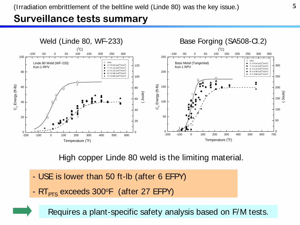
Surveillance tests summarySurveillance tests summary
-200 -100 0 100 200 300 400 500 6000
20
40
60
80
100
Temperature (oF)
CV E
nerg
y (ft
-lb)
Unirr. V, f=0.54 (x1019n/cm2) T, f=1.12 (x1019n/cm2) S, f=1.22 (x1019n/cm2) R, f=2.99 (x1019n/cm2) P, f=3.88 (x1019n/cm2)
-100 -50 0 50 100 150 200 250 300
0
20
40
60
80
100
120
2
( Jou
le)
(oC)
2
Linde 80 Weld (WF-233)Kori-1 RPV
-200 -100 0 100 200 300 400 500 600 7000
50
100
150
200
250
Temperature (oF)
CV E
nerg
y (ft
-lb)
Unirr. V, f=0.54 (x1019n/cm2) T, f=1.12 (x1019n/cm2) S, f=1.22 (x1019n/cm2) R, f=2.99 (x1019n/cm2) P, f=3.88 (x1019n/cm2)
-100 -50 0 50 100 150 200 250 300 350
0
50
100
150
200
250
300
( Jou
le)
(oC)
Base Metal (Tangential)Kori-1 RPV
2
Weld (Linde 80, WF-233) Base Forging (SA508-Cl.2)
High copper Linde 80 weld is the limiting material.
- USE is lower than 50 ft-lb (after 6 EFPY)
- RTPTS exceeds 300oF (after 27 EFPY)
Requires a plant-specific safety analysis based on F/M tests.
(Irradiation embrittlement of the beltline weld (Linde 80) was the key issue.)

6
-100 -50 0 50 100 150 200 250 3000
20
40
60
80
100
120
140
160
72W (~1.75x10¹⁹n/cm2)
WF-233 (~2.79x10¹⁹n/cm2)
WF-233 (Un-irr)
72W (Un-irr)
Ene
rgy
(J)
Temperature (oC)
Linde
80 (Linde
1092) flux welds issues
USE is low.
RTNDT is high.
Plant-specific safety analysis was necessary to conform to the regulatory rules.
Several NPP’s constructed in USA in early 70’s (including Kori-1, Korea) are expected to exceed the screening criteria during the life extension period.
Many investigations have been focused on these materials.

7
Automatic Submerged-arc weld processCu plated* Mn-Mo-Ni filler wire and Linde 80 flux (SiO2 +8-10%MnO)
Standard welding practice in USA, 1967-1971
* Electrical conductance during weldingCorrosion resistance during storage
Low upper-shelf, High copper Linde
80 flux weldLow upper-shelf, High copper Linde
80 flux weld
<ex, WF-233>
Cu : ~0.23 wt%
Ni : ~0.61 wt%
P, S : ~0.016 wt%
C : ~0.1 wt%
Mn : ~1.6 wt%
Si, Mo : ~0.5 wt%

8
Metallurgical investigations
Mn-Si-Al type inclusions prevail among the inside microstructure.
The inclusions act like a cleavage initiation site for brittle fracture.

9Regulatory actions related to the Charpy
properties
Low upper-shelf toughness (<50 ft-lb)
•An equivalent fracture mechanics analysis based on the J-R method.
•USNRC RG-1.161 provides both the evaluation procedure and J-R database.
High RTNDT (RTPTS ) (>300oF)
•A direct estimation of fracture toughness by using the “Master Curve” method (ASTM Standard E1921: To , A reference temperature describing
ductile-brittle transition of fracture toughness )
•ASME Code Case N-629: RTTo , An alternative indexing of RTNDT
RTTo = To + 35oF
Plant-specific fracture mechanics analysis based on
the fracture toughness data rather than the Charpy impact data.
Master Curve
Approach

10Similar issues in WWER-440 RPV
• Some reactors (V-230) do not have surveillance programs and “boat-samples” were taken from the RPV inner surface of operated units.
• Design concept was transportable by land (by train and/or by road). => Smaller diameter and thinner wall with higher strength materials => Smaller water gap thickness between fuel and the vessel wall => Higher neutron flux on the wall =>requires higher resistance against IE
• Relatively high content of phosphorus in the beltline welds (~0.03wt%) Copper content is also relatively high (0.15~0.20wt%) Limited information about initial transition temperature.
• Some reactor vessels were thermally annealed to recover the embrittlement. => Studied on re-embrittlement mechanisms, kinetics and prediction models
IAEA Coordinated Research Programs.
IAEA International Database on RPV materials (IDRPVM)
Master Curve
Approach

11
Efforts to solve the Kori-1 case
S1: Low upper-shelf issue (J-R tests)S2: Plant specific PTS analysis
(probabilistic fracture mechanics)S3: RTPTS re-evaluation
(by Master curve testing)S4: Pressure-temperature limit curve
(by Code case N-641)
Irradiation embrittlement of the beltline weld (Linde 80) was the key.

12History of safety evaluation of irradiation embrittlement
5th Surveillance tests (Charpy) (1980, 1984, 1986, 1990, 2000)
Low upper-shelf evaluation (J-R tests by modified 1X-WOL specimens)
• 1988, per NUREG-0744
• 1994 & 2005, per USNRC DG-1023 & USNRC RG-1.161
Master curve fracture toughness tests (RTPTS re-evaluation)
• Unirradiated archive weld (2000, ASTM E1921-97)
• Irradiated tests by reconstituted specimens (2006, 3/4/5 capsules)
• Additional unirradiated tests (2006, ASTM E1921-05)
Plant-specific analysis of PTS, based on the probabilistic fracture mechanics, USNRC RG-1.154 (2003)
P-T limit curve was revised by CC N-641 (circumferential flaw, 2004)

13S1: Low upperS1: Low upper--shelf energy => Jshelf energy => J--R tests & analysisR tests & analysis
Elastic-plastic fracture mechanics methodology (J-R) :
J-T method, DPFAD, J-R CDF
USNRC RG-1.161 (1995) provides the safety criteria and J-R database.
Kori-1 produced its plant specific J-R data from irradiated WOL specimens.
1X-WOL Specimen
RotationAdapter
Flat Bottom Hole
1X-WOL Specimen
RotationAdapter
Flat Bottom Hole
without adapter with adapterwithout adapter with adapter

14
0.0 0.1 0.2 0.3 0.4 0.50
100
200
300
400
500
600
CR=100 oF/hr
J-in
tegr
al (l
b/in
.)
Crack Extension, a (in.)
Lower bound J-R applied J (SF=1.25)
Check Point for Crack Initiation
Levels A/B margin
24 EFPY
32 EFPY
0.0 0.1 0.2 0.3 0.4 0.50
100
200
300
400
500
600
CR=600 oF/hr
32 EFPY
J-in
tegr
al (l
b/in
.)
Crack Extension, a (in.)
Lower bound J-R applied J (SF=1.0)
Check Point for Crack Initiation
Level D margin
24 EFPY
0 2 4 6 8 10 120
200
400
600
800
1000
1200
analysis by RG-1.161
J applied at a =0.1t'+t cL+0.1 inch
Margin
32EFPY24EFPY
J In
tegr
al (i
n-lb
s/in
2 )
Transient time (Minutes)
SLB-II
Mean J0.1
Lower bound J0.1
0 5 10 15 20 250
200
400
600
800
1000
1200
analysis by RG-1.161
J applied at a =0.1t'+t cL+0.1 inch
Margin
32EFPY24EFPY
J In
tegr
al (i
n-lb
s/in
2 )
Transient time (Minutes)
SLB-I
Mean J0.1
Lower bound J0.1
0 5 10 15 20 25 30 350
200
400
600
800
1000
1200
analysis by RG-1.161
Margin
32EFPY24EFPY
J applied at a =0.1t'+t cL+0.1 inch
J In
tegr
al (i
n-lb
s/in
2 )
Transient time (Minutes)
TPSLB
Mean J0.1
Lower bound J0.1
0 2 4 6 8 10 120
200
400
600
800
1000
1200
analysis by RG-1.161
J applied at a =0.1t'+t cL+0.1 inch
Margin
32EFPY24EFPY
J In
tegr
al (i
n-lb
s/in
2 )Transient time (Minutes)
LOCA
Mean J0.1
Lower bound J0.1
A generic analysis and the plant specific analysis demonstrated a sufficient safety margin against ductile failure at the upper-shelf region.

15
S2: Plant specific PTS analysis by R.G. 1.154S2: Plant specific PTS analysis by R.G. 1.154
Initiating Events and Sequences Quantification
Thermal Hydraulic Analyses of System Transients
Mixing Analysis
Probabilistic Fracture Mechanics Analysis
Integrated PTS Risk and Sensitivity

16
Flow chart of
Plant specific
PTS evaluation

17
PFM:
Probabilistic fracture
mechanics analysis
Loading Condition - Temperature - Pressure - Heat Transfer Coeff.
Material Property - E, , , , K, Cp for Clad & Base Metal
Vessel Geometry - Vessel Diameter - Vessel Thickness - Clad Thickness
Stress Analysis• Heat Transfer• Thermal S tress• Pressure Induced S tress
Max. KIC
KI > KICKI > KIa
Material Property - Cu, Ni, RTNDT o - Fluence
Flaw Property - Flaw Distribution - Flaw Density - Location & Shape
SIF K Calculation
• K I = KI )Press + KI )Thermal
Adjusted RTNDT KIC, KIa Calculation
Irradiated fPlastic Instability
TWCFrequency
Failure Probability
• Include 95% Confidence Limit
<Computer Codes>
RETRAN-3D
RELAP5/Mod3.2
VISA-II
Favor
…

18Probabilistic fracture mechanics analysis
Input:geometry, material properties,
residual stress, T/H inputs
calculate T(t, a) withinVessel
thermal stress ST(t, a) pressure stress SP(t, a) residual stress SR(t, a)
Overall applied stress intensity factorKapp(t, a) = KT(t, a) + KP(t, a) + KR(t, a)
fluence, Cu & Ni contentRTNDT(a) = IRTNDT(a) + RTNDT(a)
stress intensity factor, KT(t, a) stress intensity factor, KP(t, a) stress intensity factor, KR(t, a)
Fracture toughness from referencecurve, KIC(t, a) & KIR(t, a)
Kapp > KIC, KIR ? Crack growth orfailureNo failure YesNo
Each variable in this box will besimulated in probabilistic analysis
Det
erm
inis
tic
Pro
babi
listi
c

19
Sequence Quantification and Grouping
Initiatingevent Power Group
name Grouping Criteria RepresentativeSequence Sequence Frequency
A1 All actuation & oprtor act’n succ. A001 A001 8.089E-04A2 Auxiliary feedwater overfeed A014 A002, A004, A005, A007A008,
A010, A011, 013, A014, A015 3.070E-04
A3 <2 stm dmp vv fail to close Ab25(1) A016~A024, A027~A031 1.389E-05A4 >2 stm dmp vv fail to close C1, C3, C4 A033, A035, A036, A038A039 2.698E-07
FullPower
A5 Frequency < E-10/yr ResidualA003, A006, A009, A012,A025, A026, A032, A034,A037, A040, A041
3.517E-09
B1 All actuation & oprtor act’n succ B001 B001 2.718E-04
B2 Auxiliary feedwater & charging flow overfeed B014 B002, B004, B005, B007,B008
B010, B011, B013, B014 1.032E-04
SmallMSLB
HotZero
Power B3 Residual(Frequency < E-10/yr) Residual B003, B006, B009, B012,B015 7.908E-10C1 All actuation & oprtor act’n succ C005 C001, C002, C004, C005 7.277E-04C2 1 steam generator blowdown C007 C007 5.895E-04C3 1 SG BD & aux. fw overfeed C011 C008, C010, C011 6.919E-05C4 1 SG BD & chg flow overfeed C014 C013, C014 7.319E-05C5 2 steam generators blowdown Cb17(2) C016, C017, C018 4.380E-07
FullPower
C6 Frequency < E-10/yr Residual C003, C006, C009, C012,C015, C019
1.813E-09
D1 All actuation & oprtor act’n succ D005 D001, D002, D004,D005 2.243E-05D2 1 steam generator blowdown D006 D006 1.817E-05D3 1 SG BD & aux. fw overfeed D012 D007, D009∼D012 4.388E-06D4 2 steam generators blowdown D013 D013 1.350E-08
LargeMSLB
HotZero
PowerD5 Frequency < E-10/yr Residual D003, D008, D014 4.856E-11
Total 29 24 134

20Calculated through-wall-cracking frequency of Kori-1 RPV
Integrated PTS Risk
Total TWC, ∑(f(i)
P(F/E)i)
Less than 5.0x10⁻⁶/Rx-yr
4.7x10⁻⁷ /Rx-yr
At 32EFPY
SGTR & SBLOCA Represent >90%of Total Risk

21
P a r a m e te r S e n s it iv it y(T W C I / T W C o )
F la w d e n s it y 7 4 .3 7 D o w n c o m e r flu i d t e m p e ra tu re 1 3 .1 5 E v e n t fr e q u e n c y o f S G T R a t H Z P 3 .0 6 C o p p e r c o n te n t s 2 .2 9 In it ia l R T N D T 2 .2 5
Sensitivity study on PFM analysis
To see
• Priorities of the inputs
• What plant conditions modified to reduce the probability of through wall crack (TWC)
• Change in TWC when a parameter changes
Flaw Density is the Most Sensitive Parameter
22
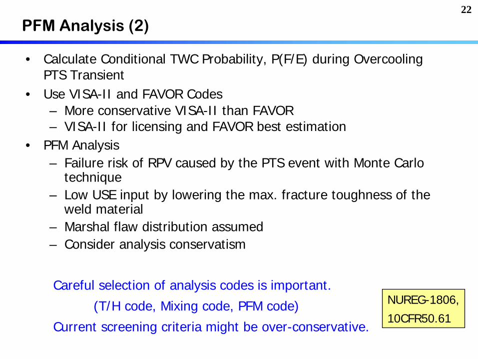
PFM Analysis (2)
• Calculate Conditional TWC Probability, P(F/E) during Overcooling PTS Transient
• Use VISA-II and FAVOR Codes– More conservative VISA-II than FAVOR– VISA-II for licensing and FAVOR best estimation
• PFM Analysis– Failure risk of RPV caused by the PTS event with Monte Carlo
technique – Low USE input by lowering the max. fracture toughness of the
weld material– Marshal flaw distribution assumed– Consider analysis conservatism
Careful selection of analysis codes is important.
(T/H code, Mixing code, PFM code)
Current screening criteria might be over-conservative.
NUREG-1806,
10CFR50.61

23
initial RTNDT :
Conservative value from NDTT and Charpy T50ft-lb -60oF
Irraidated RTNDT : RTNDT = initialTNDT + RTNDT + Margin
RTNDT : Increase of 30ft-lb temperature by irradiation
RTNDT is determined too high by Charpy v-notch tests for low toughness materials.
-200 -100 0 100 200 300 400 500 6000
20
40
60
80
100
Temperature (oF)
CV E
nerg
y (ft
-lb)
Unirr. V, f=0.54 (x1019n/cm2) T, f=1.12 (x1019n/cm2) S, f=1.22 (x1019n/cm2) R, f=2.99 (x1019n/cm2) P, f=3.88 (x1019n/cm2)
-100 -50 0 50 100 150 200 250 300
0
20
40
60
80
100
120
2
( Jou
le)
(oC)
2
Linde 80 Weld (WF-233)Kori-1 RPV
Direct evaluation of fracture toughness based on the Master curve method by using Weld Reconstitution
S3: RTS3: RTPTSPTS rere--evaluation by Master curve tests evaluation by Master curve tests

24Master Curve Test Method (ASTM E1921) (1)
m
T
XXJCTJC B
BKKKK/1
1min)(min)1(
Standard Test Method for Determination of Reference Temperature, To , for Ferritic Steels in the Transition Range
Conventional concept: Fracture toughness decreases with specimen size and the standard requires relatively large specimens for validity.
Master Curve Concept: Dependence of cleavage fracture toughness on specimen size (thickness) can be quantified by a statistical weakest-link model.
•Cleavage fracture is initiated at the weakest site ahead of crack tip.
•Large specimens have a bigger probability to get the weakest site.
(Empirically, Kmin =20MPam for RPV steels)

25
Large specimens should be used to get a valid fracture toughness.
Specimen size-dependence on the measured (cleavage) fracture
toughness can be compensated by a weakest-link theory.
Cleavage fracture toughness
data from the same (1 inch)
size specimens show a single
master curve shape for ferritic
RPV steels.
To (reference temperature) :
at 100 MPam median value
Master Curve Test Method (ASTM E1921) (2)
KIC
KJC
T – To (oF)
Indexing Fracture Toughness For Many Different RPV Steels
(NUREG-1807, by Mark Kirk)Charpy-size specimens (PCVN) can be valid
for direct indexing of fracture toughness.

26
ASME KIC Curve:
WRC Bulletin-175 (1972)
Fracture toughness data were normalized by RTNDT
parameter from Charpy tests, conservatively.
Irradiated KIC curves :
Those are shifted by the same amount of T30ft-lb
from Charpy tests.ASME KIC Curve (lower bound) and its original database (1972)
C),mMPa(in)](036.0exp[*783.225.36 oNDTIC RTTK
174 Data pointsEPRI NP-719-SR
HSST-02 plateA533B-1 steel
ASME KIC
curve : CLB (Current Licensing Basis)
assuming
How to get a fracture toughness data ?

27Size correction based on the Weibull fracture probability
Master curve testing works properly even for smaller specimens as a half sized Charpy(precracked).

28
0
50
100
150
200
250
0 50 100 150 200 250
T 41J [oC]
T o
[o C
]
Weld Fit (Slope=0.99)Plate Fit (Slope=1.10)Forging Fit (Slope=1.50)WeldPlateForgings
2
Kori-1 Weld
0
50
100
150
200
250
0 50 100 150 200 250
T 41J [oC]
T o
[o C
]
Weld Fit (Slope=0.99)Plate Fit (Slope=1.10)Forging Fit (Slope=1.50)WeldPlateForgings
2
Kori-1 Weld
Equivalence to the current RTNDT
rules
Depends on the material.
Equivalent for the current limiting material HHST-02.
RTTo = To +35oF (from CC N-629)

29Benefits of Master Curve approach
• 10 Charpy specimens are sufficient to get a standard fracture toughness curve if pre-cracked and tested by the master curve method.
• Why should we be tied down by the indirect Charpy rules for surveillance tests ?
• During the last decade, international collaborative researches have been focused on this subject for enlargement of database (incl. irradiation) and codification of the application.
•Surveillance test standards (ASTM E185, etc.) permit the use of master curve testing.
•ASME Code provides an alternative indexing of RTNDT by RTTo (=To +35oF). RTTo is very useful for the case of lack of the initial RTNDT information.
PCVN (precracked Charpy) specimens from conventional surveillance programs can be used for master curve testing to give highly reliable results.

30Application of Master Curve for PLEX (plant life extension)
•Nuclear power plants constructed in 60~70’s, many of which have low upper- shelf high-copper beltline welds, are the focus of the life extension.
•Fracture toughness should be evaluated by using an advanced method.
•Master curve method is the most promising tool for the demonstration of margins.
How can we obtain specimens for the M/C tests if all surveillance tests were already finished ?
=> Weld reconstitution of broken Charpy specimens
(ASTM E1253, Standard Guide for Reconstitution of Irradiated Charpy-sized Specimens)

31Weld reconstitution of broken Charpy
specimens
A broken half of Charpy specimens from surveillance programs
A new PCVN specimen for the master curve testing
Insert machining of a broken piece.
Arc stud welding in a short period (~0.2 sec)
Final machining and pre-cracking

32Validation of weld reconstitution techniquesValidation of weld reconstitution techniques
Temperature Measurements
Hardness Profiles
FEM stress calculation -250 -200 -150 -100 -50 0 500
50
100
150
200
250
300
Virgin PCVN (T0= -106oC)Reconstitution (T0= -105.2oC)
K JC,1
T (M
Pa-
m0.
5 )
Temperature (oC)
Practically,the same.

33
• Best-estimation To (-106.7oC) value (E1921-05) envelopes the all data by the ASME code case N-629, RTTo curve.
• A conservative To (-83.3oC) value was calculated from a minimum property data set at a single temperature for the initial RTTo value determination .(Implicit margin of about 23.4oC was added to Kori-1 safety analysis.)
UnUn--irradiated material data (WFirradiated material data (WF--233)233)
-150 -120 -90 -60 -30 00
50
100
150
200
250
300
KIC Curve onRTTo without margin
K1W Pre-irradiationPCVN specimensT
o,ASTM= -106.7 oC
K JC, 1
T-ad
just
ed (M
Pa-m
0.5 )
Test Temperature (oC)
0.5 mm/min 0.15 mm/min 0.15 mm/min (recon.)
-150 -120 -90 -60 -30 0 300
50
100
150
200
250
300
KIC Curve onRTTo without margin
K1W Pre-irradiationPCVN specimensTo, conservative= -83.3 oC
K JC, 1
T-ad
just
ed (M
Pa-m
0.5 )
Test Temperature (oC)
0.5 mm/min 0.15 mm/min 0.15 mm/min (recon.)
Standard To value from all data(E1921-05)
Conservative To value from a data set at a single temperature (E1921-97)

34Comparison with US data for Comparison with US data for LindeLinde 80 welds80 welds
Kori-1 RPV weld showed a better property
than the generic Linde 80 data.• 2σ= 65.8oF
• PCVN bias = 18oF
• Explicit margin terms will be added for integrity evaluation.
Un-irradiated Irradiated
-200 -150 -100 -50 0 500
50
100
150
200
250
300
ASME KIC curve by RTTo without any marginbased on the generic value of -47.6oF
Linde 80 Unirradiated Data
BAW-2308 Kori-1 ('97) Kori-1 ('05)
K JC -
adju
sted
to 1
T (M
Pa-m
0.5 )
Test Temperature (oC)-50 0 50 100 150
0
50
100
150
200
250Fracture Toughness Data of Irradiated Linde 80 Welds
Fluence (x1019 n/cm2)BAW-2308 : 0.8 ~ 2.0 Kori-1 weld : 1.1 ~ 3.9
KIC - RTTo curve without any marginbased on the 5th capsule fluence
K JC, 1
T-ad
just
ed (M
Pa-m
0.5 )
Temperature (oC)
BAW-2308 Kori-1 (3rd) Kori-1 (4th) Kori-1 (5th)
(To,ASTM = 13.4, 30.0, 31.5 oC)
35
0
50
100
150
200
250
0 50 100 150 200 250
T 41J [oC]
T o
[o C
]
Weld Fit (Slope=0.99)Plate Fit (Slope=1.10)Forging Fit (Slope=1.50)WeldPlateForgings
2
Kori-1 Weld
0
50
100
150
200
250
0 50 100 150 200 250
T 41J [oC]
T o
[o C
]
Weld Fit (Slope=0.99)Plate Fit (Slope=1.10)Forging Fit (Slope=1.50)WeldPlateForgings
2
Kori-1 Weld
(NUREG-1807 database)
<RPV steels & welds>
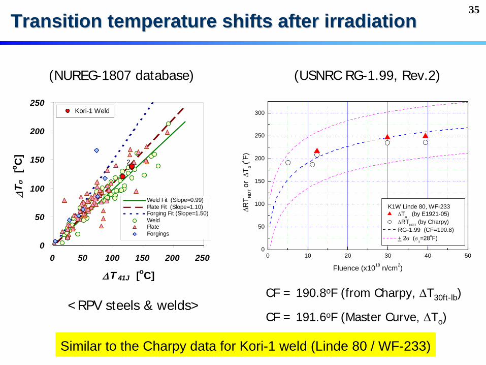
Transition temperature shifts after irradiationTransition temperature shifts after irradiation
(USNRC RG-1.99, Rev.2)
CF = 190.8oF (from Charpy, T30ft-lb )
CF = 191.6oF (Master Curve, To )
0 10 20 30 40 500
50
100
150
200
250
300
RT N
DT o
r T
o (o F)
Fluence (x1018 n/cm2)
K1W Linde 80, WF-233 To (by E1921-05) RTNDT (by Charpy) RG-1.99 (CF=190.8) + 2 (
=28oF)
Similar to the Charpy data for Kori-1 weld (Linde 80 / WF-233)

36
Master curve Charpy based
Un-irradiated To,ASTM (oC) -106.7 -
Initial (conservative) To (oC) -83.3 -
PCVN Bias (oC) 10 -
RTTo correction (oC) 19.4 -
Initial RTTo (oC) -53.9 -
Initial RTTo (oF) -65 -10 (RTNDT )
CF (oF) 191.6 190.8
Margin (oF) 65.8 56
Fluence at EOLE (40 yr) 3.94 3.94
RTPTS (oF) at 40 yr 260.0 304
RTRTPTSPTS rere--evaluation (from conservative initial data)evaluation (from conservative initial data)
BAW-2308 approach
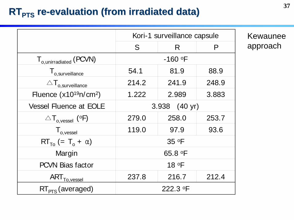
37
Kori-1 surveillance capsule
S R P
To,unirradiated (PCVN) -160 oF
To,surveillance 54.1 81.9 88.9
△To,surveillance 214.2 241.9 248.9
Fluence (x1019n/cm2) 1.222 2.989 3.883
Vessel Fluence at EOLE 3.938 (40 yr)
△To,vessel (oF) 279.0 258.0 253.7
To,vessel 119.0 97.9 93.6
RTTo (= To + α) 35 oF
Margin 65.8 oF
PCVN Bias factor 18 oF
ARTTo,vessel 237.8 216.7 212.4
RTPTS (averaged) 222.3 oF
RTRTPTSPTS rere--evaluation (from irradiated data)evaluation (from irradiated data)
Kewauneeapproach

38RTPTS
evolution curve revised for Kori-1 weld
0 10 20 30 40 50100
150
200
250
300
350
4000 10 20 30 40 50
Fracture toughness evaluationby the master curve testsincluding safety margin
Approximate Calendar Year of Kori-1
Surveillance Charpy dataincluding safety margin
Regulatory Reference
RT PT
S (o F)
Neutron Fluence (x1018n/cm2)
Master curve fracture toughness data (36 un-irradiated & 45 irradiated)showed a sufficient RTPTS margin for another 10 years and more operation.

39S4: PS4: P--T (pressureT (pressure--temperature) operation limit curvetemperature) operation limit curve
•ASME Code Section XI, App.G assumes an axial surface crack of 1/4t depth.
•The operating window was too narrow for Kori-1, which has no axial weld.
•ASME Code Case N-641 permits a postulate flaw with a circumferential orientation, if there are only circumferential welds.
=> This could reduce the stress intensity and the P-T curve constraint.
0
250
500
750
1000
1250
1500
1750
2000
2250
2500
0 50 100 150 200 250 300 350 400 450 500 550
Temperature (Deg. F)
Pres
sure
(psi
g)
ASMEsec.XI,App. G.
Code caseN-641
150 oF
800p
sig
Operating window was increased by the code case N-641 application.
Master curve data is not applied to the P-T curve generation for Kori-1.

40
PSR (Periodic Safety Review)
PLiM (Plant Lifetime Management) or AMP (Aging Management Program)
LTO (Long Term Operation) or CO (Continued Operation) or LR (License Renewal)
Code & Rules for Life Extension (Continued Operation)
<Presentation on Day-3>

41
Regulatory Requirement of PSR
• IAEA Convention on Nuclear Safety(1996.10)recommends Member States to adopt PSR
Safety Fundamentals
Safety Requirements
Safety Guides
The Safety of Nuclear Installations, Safety Series No. 110 (1993)
Safety of NPPs: Operation, Safety Std Series No. NS-R-2 (2000)
Periodic Safety Review of NPPs, Safety Guide No. NS-G-2 (2003)
PSR of Operational NPPs, Safety Guide No. 50-SG-O12 (1994)

42
Legal Basis of PSR in Korea
Atomic Energy Act (’01.1.16)(Article 23 : PSR)
Enforcement Decree of the Act (Article 42 : Content of PSR)
Enforcement Regulation of the Act (Article 19 : Details of PSR)
Associate Regulatory Guides of MOSTCodes & Standards in FSAR
11 Safety Factors
55 Detailed Items of Safety Factors
PSR Responsibility of NPP Owner
• Governmental policy on PSR issued(1999.12)
(原子力法)
(施行令)
(施行規則)
PSR of Operational NPPs, IAEA Safety Guide No. 50-SG-O12 (1994)

43
• ’99.12: Governmental policy on PSR issued
• ’00.5 ~ ’02.11(30 months): PSR on Kori Unit 1 done
- 706.8 MM involved /Budget of $ 3million
• ’03.11: Regulator(MOST) finished the review of PSR
report
• ’05.6~’06.6: Extended PSR done for continued operation
• ’07.7: IAEA SALTO peer review done
• ’07.12: Continued operation to be decided
History of PSR on Kori
Unit 1
SALTO: Safety Aspects of Long Term Operation

44
Result of PSR on Kori
Unit 1
Safety factor (aging management) Determine whether aging is being effectively managed
and an effective AMP is in place Safety-related SSC maintained in good condition Some AMP should be upgraded
Some aged SSC’s replaced before and during PSR LP turbine rotor(’97.6), Steam generators (’98.9) Main transformer(’01.10), Generator/exciter(’05.5) ATWS mitigation system installed(’01.12)
Total 40 safety improvements recommended Installation of fatigue monitoring system Preparation of alloy 600 management program Performance of equipment qualification, etc
Conclusion of PSR on Kori Unit 1 Maintained good physical and operational condition Sufficient safety margin ensured for the safe operation

45
’05.6~’06.6: Extended PSR done for continued operation beyond design life (2007.6.9) PSR report Aging management program including TLAA Statement of radiological impact on environments
’07.7.23~8.3: IAEA SALTOpeer review done
PSR on Kori
Unit 1 for CO/LTO
Kori-1 received the CO permission and public agreement with residents
in Dec. 2007
and re-started a 10 year operation in Jan. 2008.

46
Further consideration of Kori-1 LTO (I)
Fatigue (thermal/environmental) was another TLAA issue.
Very high CUF when considering PWR environmental effects.
Guidelines for environmental fatigue evaluation are on-going issue in USNRC, ASME, worldwide.
For Kori-1, 10 year life extension (from 30 to 40 years) was given at this time.
For another 10 or 20 year operation (60 years), environmental fatigue issue should be resolved as well as irradiation embrittlement.

47
Further consideration of Kori-1 LTO (II)
USNRC published an alternative guide for integrity assessment of irradiation embrittlement for radiation sensitive RPV.
Risk-informed integrity assessment with a revised embrittlement model
Based on the probabilistic fracture mechanics evaluation
NUREG-1874: Recommended Screening Limits for Pressurized Thermal Shock (PTS)
Proposed Rules (10CFR50.61a) : Alternate Fracture Toughness Requirements for Protection Against Pressurized Thermal Shock Events, Federal Register, Vol.72, No.191, Oct. 3, 2007

48
Summary (I)
An application for a 10 year extension of the operating license for the first PWR in Korea, Kori-1, has been submitted to the government after a stable operation of its initial licensing period of 30 years.
Safety evaluation and aging management actions on irradiation embrittlement of Kori-1 RPV were successfully performed and approved.
• RTPTS was re-evaluated through the master curve test method using a total of 45 irradiated and 36 un-irradiated PCVN specimens for the limiting material, the beltline circumferential weld, Linde 80 WF-233.
• Low upper-shelf toughness issues were resolved by J-R testing of the irradiated WOL specimens and using the USNRC RG-1.161 procedure.
• P-T limit curve was revised by using the Code Case N-641.
• The plant specific PTS analysis by RG 1.154 showed that the total failure risk is lower than 5x10⁻⁷ through probabilistic fracture mechanics analysis.

49
Summary (II)
An ex-vessel dosimetry system was installed for a continuous monitoring and improvement of the calculation accuracy of neutron fluence during a continued operation of Kori-1.
PSR, PLiM, AMP and CO/LTO are successfully implemented in operating NPPs.
• PSR is performed every 10 years.
• An intensive PSR is carried out for LTO (license renewal)
• Aging management programs are implemented.
• Some aged components like SG were replaced.
• PWSCC sensitive parts will be replaced or repaired by weld overlay with more corrosion resistant materials.
• Plant life management database was developed for the effective maintenance of each NPP.