lidar base specification version 1.0 lidar base specification - usgs
TRANSCRIPT
National Geospatial Program
Lidar Base Specification Version 1.0
Chapter 4 ofSection B, U.S. Geological Survey StandardsBook 11, Collection and Delineation of Spatial Data
Techniques and Methods 11–B4
U.S. Department of the InteriorU.S. Geological SurveyU.S. Department of the InteriorU.S. Geological Survey
Techniques and Methods 11–B4Techniques and Methods 11–B4
National Geospatial Program
Lidar Base Specification Version 1.0
Chapter 4 ofSection B, U.S. Geological Survey StandardsBook 11, Collection and Delineation of Spatial Data

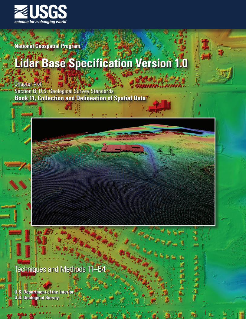
Cover. Background: Image depicts a hillshade first-return lidar surface of a suburban area of Sioux Falls, South Dakota. Front cover inset: Image depicts a perspective view of an all-return lidar point cloud. Back cover inset: Image depicts a hillshade perspective view of a hydro-flattened bare-earth lidar surface of Palisades State Park in Garretson, South Dakota.

Lidar Base Specification Version 1.0
By Hans Karl Heidemann
Chapter 4 ofSection B, U.S. Geological Survey StandardsBook 11, Collection and Delineation of Spatial Data
National Geospatial Program
Techniques and Methods 11–B4
U.S. Department of the InteriorU.S. Geological Survey

U.S. Department of the InteriorKEN SALAZAR, Secretary
U.S. Geological SurveyMarcia K. McNutt, Director
U.S. Geological Survey, Reston, Virginia: 2012
For more information on the USGS—the Federal source for science about the Earth, its natural and living resources, natural hazards, and the environment, visit http://www.usgs.gov or call 1–888–ASK–USGS.
For an overview of USGS information products, including maps, imagery, and publications, visit http://www.usgs.gov/pubprod
To order this and other USGS information products, visit http://store.usgs.gov
Any use of trade, product, or firm names is for descriptive purposes only and does not imply endorsement by the U.S. Government.
Although this report is in the public domain, permission must be secured from the individual copyright owners to reproduce any copyrighted materials contained within this report.
Suggested citation:Heidemann, Hans Karl, 2012, Lidar base specification version 1.0: U.S. Geological Survey Techniques and Methods, book 11, chap. B4, 63 p.
iii
Contents
Introductory Material ....................................................................................................................................1Purpose and Scope ..............................................................................................................................1Applicability ...........................................................................................................................................1Maintenance Authority ........................................................................................................................2Background............................................................................................................................................2
Collection.........................................................................................................................................................2Multiple Discrete Returns ...................................................................................................................2Intensity Values .....................................................................................................................................2Nominal Pulse Spacing (NPS) ............................................................................................................2Data Voids ..............................................................................................................................................2Spatial Distribution ...............................................................................................................................3Scan Angle .............................................................................................................................................3Vertical Accuracy .................................................................................................................................3Relative Accuracy.................................................................................................................................4Flightline Overlap ..................................................................................................................................4Collection Area ......................................................................................................................................4Collection Conditions ..........................................................................................................................4
Data Processing and Handling ....................................................................................................................5ASPRS LAS File Format ........................................................................................................................5Full Waveform ........................................................................................................................................5Global Positioning System (GPS) Times ............................................................................................5Datums ....................................................................................................................................................5Coordinate Reference System ............................................................................................................5Units of Reference ................................................................................................................................5Swath Identification .............................................................................................................................6Point Families ........................................................................................................................................6Swath Size and Segmentation ............................................................................................................6Scope of Collection ..............................................................................................................................6Use of the LAS Withheld Flag .............................................................................................................6Point Classification ...............................................................................................................................6Positional Accuracy Validation .........................................................................................................7Classification Accuracy .......................................................................................................................7Classification Consistency ..................................................................................................................7Tiles .........................................................................................................................................................7
Hydro-Flattening.............................................................................................................................................8Inland Ponds and Lakes .......................................................................................................................8Inland Streams and Rivers .................................................................................................................8Non-Tidal Boundary Waters ...............................................................................................................8Tidal Waters ...........................................................................................................................................8Islands.....................................................................................................................................................9Single-Line Streams .............................................................................................................................9
Deliverables ...................................................................................................................................................9

iv
Metadata ................................................................................................................................................9Raw Point Cloud ..................................................................................................................................10Classified Point Cloud ........................................................................................................................10Bare-Earth Surface (Raster DEM) ...................................................................................................11Breaklines ............................................................................................................................................12
References Cited..........................................................................................................................................12Glossary .........................................................................................................................................................13Appendixes ...................................................................................................................................................23Appendix 1. Common Data Upgrades ...................................................................................................24Appendix 2. Guidelines ............................................................................................................................25
Scan Angle ...........................................................................................................................................25Swath Size............................................................................................................................................25Non-Tidal Boundary Waters .............................................................................................................25Tidal Waters .........................................................................................................................................25Breaklines and Hydro-Flattening .....................................................................................................25
Appendix 3. Hydro-Flattening Reference .............................................................................................26Appendix 4. Lidar Metadata Example ...................................................................................................28Appendix 5. Lidar Metadata Template ..................................................................................................37Supplemental Information ..........................................................................................................................63
TablesTable 1. Minimum Classified Point Cloud Classification Scheme. ....................................................11
Conversion FactorsMultiply By To obtain
Length
centimeter (cm) 0.3937 inch (in.)meter (m) 3.281 foot (ft) kilometer (km) 0.6214 mile (mi)meter (m) 1.094 yard (yd)
Area
square meter (m2) 0.0002471 acre square meter (m2) 10.76 square foot (ft2) hectare (ha) 2.471 acrehectare (ha) 0.003861 square mile (mi2) = 640 acres = 1 sectionsquare kilometer (km2) 247.1 acresquare kilometer (km2) 0.3861022 square mile (mi2)
Altitude and Elevation, as used in this report, refers to the distance above the geoid, unless specifically referenced to the ellipsoid.
Height, as used in this report, refers to the height above ground.

v
Abbreviations and AcronymsARRA American Reinvestment and Recovery ActASPRS American Society for Photogrammetry and Remote SensingCLICK Center for Lidar Information, Coordination, and KnowledgeCONUS Conterminous United StatesCORS Continuously Operating Reference StationsCVA Consolidated Vertical AccuracyDEM Digital Elevation ModelDSM Digital Surface ModelsDTED digital terrain elevation dataDTM digital terrain modelEDNA Elevation Derivatives for National ApplicationsEPSG European Petroleum Survey GroupFGDC Federal Geographic Data CommitteeFOV field of viewFVA Fundamental Vertical AccuracyGB gigabyteGPS Global Positioning SystemGSD ground sample distanceH&H hydraulic and hydrologicIFSAR Interferometric Synthetic Aperature Radarlidar light detection and rangingIMU Inertial Measurement UnitNAD83 North American Datum of 1983NAVD88 North American Vertical Datum of 1988NDEP National Digital Elevation ProgramNED National Elevation DatasetNGP National Geospatial ProgramNGS National Geodetic SurveyNIR near infra-redNIST National Institute of Standards and TechnologyNPS Nominal Pulse SpacingNSRS National Spatial Reference SystemNSSDA National Standards for Spatial Data AccuracyOCONUS Outside the Conterminous United StatesQA/QC Quality Assurance/Quality ControlRMSE Root Mean Square ErrorSVA Supplemental Vertical AccuracyTIN Triangulated Irregular NetworkUSGS U.S. Geological SurveyUTM Universal Transverse MercatorXML eXtensible Markup Language

Lidar Base Specification Version 1.0
By Hans Karl Heidemann
Introductory Material
Purpose and Scope
The U.S. Geological Survey (USGS) intends to use this specification to acquire and procure light detection and ranging (lidar) data, and to create consistency across all USGS National Geospatial Program (NGP) and partner funded lidar collections, in particular those undertaken in support of the National Elevation Dataset (NED) (Gesch, 2007). Unlike most other “lidar data procurement specifications”, which are focused on the products derived from lidar point cloud data; such as the bare-earth Digi-tal Elevation Model (DEM), this specification places unprecedented emphasis on the handling of the source lidar point cloud data. The goal of this document is to assure that the complete acquired source dataset, including the data, metadata, descrip-tive documentation, quality information, and ancillary data—collected in accordance with the minimum parameters specified within—remains intact and viable to support the wide variety of DEM and non-DEM science and mapping applications that benefit from lidar technology. In the absence of other comprehensive specifications or standards, the USGS NGP hopes that this specification will, to the greatest degree practical, be adopted by other USGS programs and disciplines, and by other federal agencies.
Adherence to the following minimum specifications ensures that bare-earth DEMs derived from lidar data are suitable for ingestion into the NED at the 1/9 arc-second resolution, and can be resampled for use in the 1/3 and 1 arc-second NED resolu-tions. It also ensures that the point cloud source data are handled in a consistent manner by all data providers and delivered to the USGS in clearly defined formats. This allows straight-forward ingestion into lidar data management systems such as the Center for Lidar Information, Coordination, and Knowledge (CLICK) (Stoker and others, 2006) and simplifies subsequent use of the source data by the broader user community, particularly with regard to cross-collection analysis.
It must be emphasized that this is a base specification, defining minimum parameters for acceptance of the acquired lidar data. It is expected that local conditions in any given project area, specialized applications for the data, or the preferences of cooperators, may mandate more stringent requirements. The USGS encourages the collection of more detailed, accurate, or value-added data. A list of common upgrades to the minimum requirements defined in this report is provided in appendix 1.
Although lidar data have been used in the research and commercial mapping environments for more than a decade, it is still a relatively new technology. Advancements and improvements in instrumentation, software, processes, applications, and understanding are constantly refined or developed. It would not be possible to develop a set of guidelines and specifications that address all of these advances. The current document is based on the NGP’s understanding of and experience with the lidar tech-nology being used in the industry at the present time (2012). Furthermore, the NGP acknowledges that there is a lack of com-monly accepted best practices for numerous processes and technical assessments (for example, measurement of Nominal Pulse Spacing (NPS), point distribution, classification accuracy, common accuracy and quality indicators, and others). The USGS encourages the development of such best practices through its partners in the industry, other Government agencies, and the appropriate professional governance organizations, and considers them for future revisions to this and other similar documents.
Applicability
These specifications and guidelines are applicable to lidar data and deliverables supported in whole or in part, with either financial or in-kind contributions, by the USGS NGP.

2 Lidar Base Specification Version 1.0
Maintenance Authority
The USGS NGP is the maintenance authority for this document.
Background
The USGS NGP has cooperated in the collection of numerous lidar datasets across the Nation for a wide array of applica-tions. These collections used a variety of specifications and had a diverse set of product deliverables, resulting in incompatible datasets and making cross-project analysis extremely difficult. The need for a single base specification, defining minimum col-lection parameters and a consistent set of deliverables, is apparent.
Beginning in late 2009, an increase in the rate of lidar data collection because of the American Reinvestment and Recovery Act (ARRA) funding for The National Map made it imperative that a single data specification be implemented to ensure consis-tency and improve data utility. Although the development of this specification was prompted by the ARRA funding, the specifi-cation is intended to remain durable beyond ARRA-funded NGP projects.
In addition, it is recognized that the USGS NGP also uses lidar technology for specialized scientific research and other proj-ects whose requirements are incompatible with the provisions of this specification. In such cases, and with properly documented justification supporting the need for the variance, waivers of any part or all of this specification may be granted.
It is conceivable that in some cases, based on specific topography, land cover, intended application, or other factors, the USGS-NGP may require specifications more rigorous than those defined in this document.
Technical alternatives to enhance delivery of data or associated products and processes as described by parameters and language in this document are encouraged and may be submitted with any proposal and will be given due professional consideration.
Collection
Multiple Discrete Returns
Data collection must be capable of at least three returns per pulse. Full waveform collection is acceptable and welcomed; however, waveform data are regarded as supplemental information. Deriving and delivering multiple discrete returns is required in all cases.
Intensity Values
Intensity values are required for each return. The values are to be recorded in the .las files in their native radiometric resolution.
Nominal Pulse Spacing (NPS)
An NPS of 2 meters or less is required. Dependent on the local terrain and land cover conditions in the project area, a greater point density may be required on specific projects. Assessment of the NPS will be made against single swath, first-return only data, located within the geometrically usable center portion (typically 90 percent) of each swath, acceptable data voids excluded. NPS will be calculated as the square root of the average area per point. Average along-track and cross-track point spacing should be comparable (within 10 percent).
In general, the target NPS for a project should not be achieved through swath overlap or multiple passes. Such collection techniques may be permitted with prior approval.
Data Voids
Data voids within a single swath are not acceptable, except in the following circumstances:• Where caused by water bodies,
Collection 3
• Where caused by areas of low near infra-red (NIR) reflectivity such as asphalt or composition roofing, or
• Where appropriately filled-in by another swath.
Spatial Distribution
The spatial distribution of geometrically usable points is expected to be uniform. Although it is understood that lidar instru-ments do not produce regularly gridded points, collections should be planned and executed to produce a first-return point cloud that approaches a regular lattice of points, rather than a collection of widely spaced high density profiles of the terrain. The uniformity of the point density throughout the dataset is important and will be assessed using the following steps:
• Generating a density grid from the data with cell sizes equal to the design NPS times 2, using a radius equal to the design NPS.
• Ensuring at least 90 percent of the cells in the grid contain at least one lidar point.
• The assessment is to be made against individual (single) swaths, using only the first-return points located within the geo-metrically usable center portion (typically 90 percent) of each swath.
• Excluding acceptable data voids previously identified in this specification. Note: This requirement may be relaxed in areas of substantial relief where it is impractical to maintain a consistent and
uniform distribution. Note: The process described in this section relates only to the uniformity of the point distribution. It in no way relates to,
nor can it be used for the assessment of point density or NPS.
Scan Angle
Scan angle will support horizontal and vertical accuracy within the requirements as specified in the next two sections. See Appendix 2 for additional information.
Note: This requirement primarily is applicable to oscillating mirror lidar systems. Other instrument technologies may be exempt from this requirement.
Vertical Accuracy
Vertical accuracy of the lidar data will be assessed and reported in accordance with the guidelines developed by the National Digital Elevation Program (NDEP) and subsequently adopted by the American Society for Photogrammetry and Remote Sensing (ASPRS). Complete definitions for vertical accuracy assessments are in Section 1.5 of the NDEP Elevation Guidelines (NDEP, 2004).
The minimum vertical accuracy requirement for the unclassified lidar point cloud, using the NDEP/ASPRS methodology, is listed below:
• Fundamental Vertical Accuracy (FVA)<= 24.5 centimeters (cm) Accuracyz (ACCz), 95 percent (12.5 cm Root Mean Square Error (RMSE)z).
The minimum vertical accuracy requirements for the derived DEM, using the NDEP/ASPRS methodology are listed below:• Fundamental Vertical Accuracy (FVA)<= 24.5 cm ACCz, 95 percent (12.5cm RMSEz);
• Consolidated Vertical Accuracy (CVA)<= 36.3cm, 95th percentile, and
• Supplemental Vertical Accuracy (SVA)<= 36.3 cm, 95th percentile.Point cloud data accuracy is to be tested against a Triangulated Irregular Network (TIN) constructed from lidar points in
clear and open areas. A clear and open area can be characterized with respect to topographic and ground cover variation such that a minimum of 5 times the NPS exists with less than 1/3 of the RMSEz deviation from a low-slope plane. Slopes that exceed 10 percent should be avoided. Ground that has been plowed or otherwise disturbed is not acceptable. All tested locations should be photographed showing the position of the tripod and the surrounding area ground condition.
Each land cover type representing 10 percent or more of the total project area must be tested and reported with an SVA. In areas where a land cover category is something other than forested or dense urban, the tested point should not have any

4 Lidar Base Specification Version 1.0
obstructions 45 degrees above the horizon to ensure a sufficient TIN surface. Additionally, tested areas should not be in proxim-ity to low NIR reflective surfaces such as asphalt or composition roofing materials.
The SVA value is provided as a target. It is understood that in areas of dense vegetation, swamps, or extremely difficult ter-rain, this value may be exceeded.
The CVA value is a requirement that must be met, regardless of any allowed “busts” in the SVA(s) for individual land cover types within the project.
Checkpoints for each assessment (FVA, CVA, and all SVAs) are required to be well-distributed throughout the land cover type, for the entire project area. See Glossary for definition of well-distributed.
Exceptions: These requirements may be relaxed in cases: • Where there exists a demonstrable and substantial increase in cost to obtain this accuracy.
• Where an alternate specification is needed to conform to previously contracted phases of a single larger overall collection effort, for example, multi-year statewide collections.
• Where the USGS agrees that it is reasonable and in the best interest of all stakeholders to use an alternate specification.
Relative Accuracy
The requirements for relative accuracy are listed below:• Within individual swaths:<= 7 cm RMSEz
• Within overlap between adjacent swaths:<=10 cm RMSEz
Flightline Overlap
Flightline overlap of 10 percent or greater is required to ensure there are no data gaps between the usable portions of the swaths. Collections in high relief terrain are expected to require greater overlap. Any data with gaps between the geometrically usable portions of the swaths will be rejected.
Collection Area
Data collection for the Defined Project Area, buffered by a minimum of 100 meters, is required. The buffered boundary is the Buffered Project Area.
In order that all products are consistent to the edge of the Defined Project Area, all products must be generated to the limit of the Buffered Project Area. Since these areas are being generated, they shall also be delivered.
Collection Conditions
Atmospheric conditions must be cloud and fog-free between the aircraft and ground during all collection operations.Ground conditions must be snow free. Very light, undrifted snow may be acceptable in special cases, with prior approval. Water conditions must be free of any unusual flooding or inundation, except in cases where the goal of the collection is to
map the inundation. Leaf-off vegetation conditions are preferred, however, as numerous factors beyond human control may affect the vegetative
condition at the time of any collection, the USGS NGP only requires that penetration to the ground must be adequate to produce an accurate and reliable bare-earth surface suitable for incorporation into the 1/9 (3-meter) NED. Collections for specific scien-tific research projects may be exempted from this requirement, with prior approval.

Data Processing and Handling 5
Data Processing and Handling
ASPRS LAS File Format
All processing should be carried out with the understanding that all point deliverables are required to be in fully compliant LAS format, either v1.2 or v1.3. The version selected must be used for all LAS deliverables in the project. Data producers are encouraged to review the LAS specification in detail (ASPRS, 2011).
Full Waveform
If full waveform data are collected, delivery of the waveform packets is required. LAS v1.3 deliverables with waveform data are to use external auxiliary files with the extension .wdp for the storage of waveform packet data. See the LAS v1.3 Speci-fication for additional information (ASPRS, 2011).
Global Positioning System (GPS) Times
GPS times are to be recorded as Adjusted GPS Time, at a precision sufficient to allow unique timestamps for each pulse. Adjusted GPS Time is defined to be Standard (or satellite) GPS time minus 1*109. See the LAS v1.3 Specification for more detail (ASPRS, 2011).
Datums
All data collected must be tied to the datums listed below: • Horizontal datum reference to the North American Datum of 1983/HARN adjustment (NAD83 HARN) is required.
• Vertical datum reference to the North American Vertical Datum of 1988 (NAVD 88) is required.
• The most recent National Geodetic Survey (NGS)-approved geoid model is required to perform conversions from ellip-soidal heights to orthometric heights.
Coordinate Reference System
The USGS preferred Coordinate Reference System for the Conterminous United States (CONUS) is Universal Transverse Mercator UTM, NAD83 HARN, Meters; NAVD88, Meters. Each discrete project is to be processed using the single predomi-nant UTM zone for the overall collection area.
The USGS will also accept data in other Coordinate Reference Systems that meet the conditions below:• State Plane and State Coordinate Reference Systems that have been accepted by the European Petroleum Survey Group
(EPSG) may be used.
• Coordinate Reference Systems for collections in Alaska, Hawaii, and other areas Outside the Conterminous United States (OCONUS) must be approved by the USGS before collection.
Units of Reference
All references to the unit of measure “Feet” and “Foot” must specify “International”, “Intl”, “U.S. Survey”, or “US”.
Swath Identification
Each swath will be assigned a unique File Source ID. It is required that the Point Source ID field for each point within each LAS swath file be set equal to the File Source ID before any processing of the data. See the LAS v1.3 Specification (ASPRS, 2011).

6 Lidar Base Specification Version 1.0
Point Families
Point families (multiple return “children” of a single “parent” pulse) shall be maintained intact through all processing before tiling. Multiple returns from a given pulse will be stored in sequential (collected) order.
Swath Size and Segmentation
Swath files will be 2 gigabytes (GB) in size or less. Long swaths (those which result in a LAS file larger than 2 GB) will be split into segments no greater than 2 GB each.
• Each sub-swath will retain the original File Source ID of the original complete swath.
• Points within each sub-swath will retain the Point Source ID of the original complete swath.
• Each sub-swath file will be named identically to the original complete swath, with the addition of an ordered alphabetic suffix to the name (“-a”, “-b” … “-n”). The order of the named sub-swaths shall be consistent with the collection order of the points (“-a” will be the chronological beginning of the swath; “-n” will be the chronological end of the swath).
• Point families shall be maintained intact within each sub-swath.
• Sub-swaths should be broken at the edge of the scan line.
• Other swath segmentation approaches may be acceptable, with prior approval.
Scope of Collection
All collected swaths are to be delivered as part of the Raw Data Deliverable. This includes calibration swaths and cross-ties. This in no way requires or implies that calibration swath data are to be included in product generation. All collected points are to be delivered. No points are to be deleted from the swath LAS files. Excepted from this are extraneous data outside of the buffered project area (aircraft turns, transit between the collection area and airport, transit between fill-in areas, and the like). These points may be permanently removed. Busted swaths that are being completely discarded by the vendor and re-flown do not need to be delivered.
Use of the LAS Withheld Flag
Outliers, blunders, noise points, geometrically unreliable points near the extreme edge of the swath, and other points the vendor deems unusable are to be identified using the Withheld flag, as defined in the LAS specification.
This applies primarily to points that are identified during pre-processing or through automated post-processing routines. If processing software is not capable of populating the Withheld bit, these points may be identified using Class=11. Noise points subsequently identified during manual Classification and Quality Assurance/Quality Control (QA/QC) may be
assigned the standard LAS classification value for Noise (Class=7), regardless of whether the noise is “low” or “high” relative to the ground surface.
Point Classification
• ALL points not identified as Withheld are to be classified.
• No points in the Classified LAS deliverable will be assigned Class=0.
• Use of the ASPRS/LAS Overlap classification (Class=12) is prohibited.If overlap points are required to be differentiated by the data producer or cooperating partner, they must be identified using
a method that does not interfere with their classification: • Overlap points are tagged using Bit:0 of the User Data byte, as defined in the LAS specification. (SET=Overlap).
• Overlap points are classified using the Standard Class values + 16.

Hydro-Flattening 7
• Other techniques as agreed upon in advance.The technique used to identify overlap must be clearly described in the project metadata files. Note: A standard bit flag for identification of overlap points has been included in LAS v1.4, released on November 14,
2011.
Positional Accuracy Validation
Before classification of and development of derivative products from the point cloud, verification of the vertical accuracy of the point cloud, absolute and relative, is required. The Fundamental Vertical Accuracy (absolute) is to be assessed in clear, open areas as described in the section called Vertical Accuracy above. Swath-to-swath and within swath accuracies (relative) are to be documented. A detailed report of this validation process is a required deliverable.
Classification Accuracy
It is required that due diligence in the classification process will produce data that meet the following tests: • Following classification processing, no non-withheld points should remain in Class 0.
• Within any 1 kilometer (km) x 1 km area, no more than 2 percent of non-withheld points will possess a demonstrably erroneous classification value.
• Points remaining in Class 1 that should be classified in any other required Class are subject to these accuracy require-ments and will be counted towards the 2 percent threshold.
Note: These requirements may be relaxed to accommodate collections in areas where the USGS agrees classification to be particularly difficult.
Classification Consistency
Point classification is to be consistent across the entire project. Noticeable variations in the character, texture, or quality of the classification between tiles, swaths, lifts, or other non-natural divisions will be cause for rejection of the entire deliverable.
Tiles
Note: This section assumes a projected coordinate reference system.A single non-overlapped tiling scheme (the Project Tiling Scheme) will be established and agreed upon by the data pro-
ducer and the USGS before collection. This scheme will be used for ALL tiled deliverables. • Tile size is required to be an integer multiple of the cell size of raster deliverables.
• Tiles are required to be sized using the same units as the coordinate system of the data.
• Tiles are required to be indexed in X and Y to an integer multiple of the tile’s X-Y dimensions.
• All tiled deliverables will conform to the Project Tiling Scheme, without added overlap.
• Tiled deliverables will edge-match seamlessly and without gaps.
Hydro-Flattening Note: Please refer to appendix 3 for reference information on hydro-flattening. Hydro-flattening pertains only to the creation of derived DEMs. No manipulation of or changes to originally computed lidar
point elevations are to be made. Breaklines may be used to help classify the point data. The goal of the NGP is for the delivered DEMs to represent water bodies in a cartographically and aesthetically pleasing manner. It is not the goal of the NGP to accu-rately map water surface elevations within the NED. The requirements for hydro-flattening are listed below.

8 Lidar Base Specification Version 1.0
Inland Ponds and Lakes
• 2 acres or greater surface area (approximately equal to a round pond 350 feet in diameter) at the time of collection.
• Flat and level water bodies (single elevation for every bank vertex defining a given water body).
• The entire water surface edge must be at or below the immediately surrounding terrain. The presence of floating water bodies will be cause for rejection of the deliverable.
• Long impoundments such as reservoirs, inlets, and fjords, whose water surface elevations drop when moving down-stream, are required to be treated as rivers.
Inland Streams and Rivers
• 100 feet nominal width: This should not unnecessarily break a stream or river into multiple segments. At times it may squeeze slightly below 100 feet for short segments. Data producers should use their best professional cartographic judg-ment.
• Flat and level bank-to-bank (perpendicular to the apparent flow centerline); gradient to follow the immediately surround-ing terrain. In cases of sharp turns of rapidly moving water, where the natural water surface is notably not level bank-to-bank, it is appropriate to represent the water surface as it exists in nature, while maintaining an aesthetic cartographic appearance.
• The entire water surface edge must be at or below the immediately surrounding terrain.
• Stream channels are required to break at road crossings (culvert locations). The roadway over a culvert should be con-tinuous. A culvert, regardless of size, is defined as having earth between the road surface and the top of the structure.
• Bridges are required to be removed from the DEM. Streams and rivers should be continuous at bridge locations. Bridges are defined as having an elevated deck structure that does not rest on earth.
• When the identification of a structure such as a bridge or culvert cannot be made reliably, the feature should be regarded as a culvert.
Non-Tidal Boundary Waters
• Represented only as an edge or edges within the project area; collection does not include the opposing shore.
• Water surface is to be flat and level, as appropriate for the type of water body (level for lakes; gradient for rivers)
• The entire water surface edge must be at or below the immediately surrounding terrain.
Tidal Waters
• Tidal water bodies are defined as water bodies such as oceans, seas, gulfs, bays, inlets, salt marshes, large lakes, and the like. This includes any water body that is affected by tidal variations.
• Tidal variations over the course of a collection or between different collections, will result in lateral and vertical disconti-nuities along shorelines. This is considered normal and these anomalies should be retained. The final DEM is required to represent as much ground as the collected data permits.
• Water surface is to be flat and level, to the degree allowed by the irregularities noted above.
• Scientific research projects in coastal areas often have specific requirements with regard to how tidal land-water boundar-ies are to be handled. For such projects, the requirements of the research will take precedence.

Deliverables 9
Islands
• Permanent islands 1 acre or larger shall be delineated within all water bodies.
Single-Line Streams
Cooperating partners may require collection and integration of single-line streams within their lidar projects. Although the USGS does not require these breaklines be collected or integrated, it does require that if used and incorporated into the DEMs, the following guidelines are met:
• All vertices along single-line stream breaklines are at or below the immediately surrounding terrain.
• Single-line stream breaklines are not to be used to introduce cuts into the DEM at road crossings (culverts), dams, or other such features. This is hydro-enforcement and as discussed in appendix 3 will create a non-topographic DEM that is unsuitable for integration into the NED.
• All breaklines used to modify the surface are to be delivered to the USGS with the DEMs.
Deliverables The USGS requires unrestricted rights to all delivered data and reports, which will be placed in the public domain. This
specification places no restrictions on the data provider’s rights to resell data or derivative products as they see fit.
Metadata
The term “metadata” refers to all descriptive information about the project. This includes textual reports, graphics, support-ing shapefiles, and Federal Geographic Data Committee (FGDC)-compliant metadata files. Metadata deliverables include the following items:
• Collection report detailing mission planning and flight logs.
• Survey report detailing the collection of control and reference points used for calibration and QA/QC.
• Processing report detailing calibration, classification, and product generation procedures including methodology used for breakline collection and hydro-flattening (see the section called Hydro-Flattening and appendix 3 for more information on hydro-flattening).
• QA/QC Reports (detailing the analysis, accuracy assessment and validation of the following:
• Point data (absolute, within swath, and between swath)
• Bare-earth surface (absolute)
• Other optional deliverables as appropriate
• Control and calibration points: All control and reference points used to calibrate, control, process, and validate the lidar point data or any derivative products that are to be delivered.
• Georeferenced, digital spatial representation of the precise extents of each delivered dataset. This should reflect the extents of the actual lidar source or derived product data, exclusive of TIN artifacts or raster NODATA areas. A union of tile boundaries or minimum bounding rectangles is not acceptable. ESRI Polygon shapefile or geodatabase is preferred.
• Product metadata [FGDC compliant, eXtensible Markup Language (XML) format metadata]. Metadata files for indi-vidual files are not required. One XML file is required for the following examples:
• The Overall Project: Describing the project boundary, the intent of the project, the types of data collected as part of the project, the various deliverables for the project, and other project-wide information.

10 Lidar Base Specification Version 1.0
• Each Lift: Describing the extents of the lift, the swaths included in the lift, locations of GPS base stations and control for the lift, preprocessing and calibration details for the lift, adjustment and fitting processes applied to the lift in rela-tion to other lifts, and other lift-specific information.
• Each tiled deliverable product group:
• Classified point data
• Bare-earth DEMs
• Breaklines (if used)
• Other datasets delivered under the contract (Digital Surface Models (DSM), intensity images, height surfaces, and others)
• FGDC compliant metadata must pass the USGS metadata parser (mp) with no errors. Note: Please refer to the metadata templates in appendixes 4 and 5 for additional information.
Raw Point Cloud
Delivery of the raw point cloud is a standard requirement for USGS NGP lidar projects. Raw point cloud deliverables include the following items:
• All swaths, returns, and collected points, fully calibrated and adjusted to ground, by swath.
• Fully compliant LAS v1.2 or v1.3, Point Data Record Format 1, 3, 4, or 5.
• LAS v1.3 deliverables with waveform data are to use external auxiliary files with the extension .wdp for the storage of waveform packet data. See the LAS v1.3 Specification for additional information.
• Correct and properly formatted georeference information must be included in all LAS file headers.
• GPS times are to be recorded as Adjusted GPS Time, at a precision sufficient to allow unique timestamps for each pulse.
• Intensity values (native radiometric resolution).
• One file per swath, one swath per file, file size not to exceed 2 GB, as described under the section called Swath Size and Segmentation above.
• Vertical accuracy of the lidar point data will be assessed and reported in accordance with the guidelines developed by the NDEP and subsequently adopted by the ASPRS. The complete guidelines on vertical accuracy are in Section 1.5 of the NDEP Guidelines (NDEP, 2004).
• Vertical accuracy requirements using the NDEP/ASPRS methodology for the point cloud are FVA<= 24.5 cm ACCz, 95-percent confidence level (12.5 cm RMSEz)
Classified Point Cloud
Delivery of a classified point cloud is a standard requirement for USGS NGP lidar projects. Specific scientific research projects may be exempted from this requirement. Classified point cloud deliverables include the following items:
• All project swaths, returns, and collected points, fully calibrated, adjusted to ground, and classified, by tiles. Project swaths exclude calibration swaths, cross-ties, and other swaths not used, or intended to be used, in product generation.
• Fully compliant LAS v1.2 or v1.3, Point Data Record Format 1, 3, 4, or 5.
• LAS v1.3 deliverables with waveform data are to use external auxiliary files with the extension .wdp for the storage of waveform packet data. See the LAS v1.3 Specification for additional information.
• Correct and properly formatted georeference information must be included in all LAS file headers.
• GPS times are to be recorded as Adjusted GPS Time, at a precision sufficient to allow unique timestamps for each pulse.

Deliverables 11
• Intensity values (native radiometric resolution).
• Tiled delivery, without overlap, using Project Tiling Scheme.
• Classification Scheme (minimum) as listed in table 1.
Bare-Earth Surface (Raster DEM)
Delivery of a bare-earth DEM is a standard requirement for USGS NGP lidar projects. Specific scientific research projects may be exempted from this requirement. Bare-earth surface deliverables include the following items:
• Bare-earth DEM, generated to the limits of the Buffered Project Area.
• Cell size no greater than 3 meters or 10 feet, and no less than the design Nominal Pulse Spacing (NPS).
• Delivery in an industry-standard, GIS-compatible, 32-bit floating point raster format (ERDAS .IMG preferred).
Table 1. Minimum Classified Point Cloud Classification Scheme.
Code Description
1 Processed, but unclassified2 Bare-earth ground7a Noise (low or high; manually identified; if needed)9 Water
10b Ignored Ground (Breakline proximity)11 Withheld (if the Withheld bit is not implemented in processing software)
aClass 7, Noise, is included as an adjunct to the Withheld bit. All noise points are to be identified using one of these two methods.
bClass 10, Ignored Ground, is for points previously classified as bare-earth but whose proximity to a subsequently added breakline requires that it be excluded during Digital Elevation Model (DEM) genera-tion.
• Georeference information shall be included in each raster file.
• Tiled delivery, without overlap.
• DEM tiles will show no edge artifacts or mismatch. A quilted appearance in the overall project DEM surface, whether caused by differences in processing quality or character between tiles, swaths, lifts, or other non-natural divisions, will be cause for rejection of the entire deliverable.
• Void areas (for example, areas outside the Buffered Project Area but within the tiling scheme) shall be coded using a unique NODATA value. This value shall be identified in the appropriate location within the raster file header or external support files (for example, .aux).
• Vertical accuracy of the bare-earth surface will be assessed and reported in accordance with the guidelines developed by the NDEP and subsequently adopted by the ASPRS. The complete guidelines are in Section 1.5 of the NDEP Guidelines (NDEP, 2004).
• The following threshholds represent the minimum vertical accuracy requirements using the NDEP/ASPRS methodology:
• FVA<= 24.5 cm ACCz, 95 percent Confidence Level (12.5 cm RMSEz)
• CVA<= 36.3 cm, 95th percentile
• SVA<= 36.3 cm, 95th percentile
• All QA/QC analysis materials and results are to be delivered to the USGS.

12 Lidar Base Specification Version 1.0
• Depressions (sinks), natural or man-made, are not to be filled (as in hydro-conditioning and hydro-enforcement).
• Water bodies (ponds and lakes), wide streams and rivers (double-line), and other non-tidal water bodies as defined in the section called Hydro-flattening are to be hydro-flattened within the DEM. Hydro-flattening shall be applied to all water impoundments, natural or man-made, that are larger than 2 acres in area (approximately equal to a round pond 350 feet in diameter), to all streams that are nominally wider than 100 feet, and to all non-tidal boundary waters bordering the project area regardless of size. The methodology used for hydro-flattening is at the discretion of the data producer.
Note: Please refer to the section called Hydro-Flattening and appendix 3 for detailed discussions of hydro-flattening.
Breaklines
Delivery of the breaklines used in hydro-flattening is a standard requirement for USGS NGP lidar projects. Specific scien-tific research projects may be exempted from this requirement. If hydro-flattening is achieved through other means, this section may not apply. Breakline deliverables include the following items:
• Breaklines shall be developed to the limit of the Buffered Project Area.
• All breaklines developed for use in hydro-flattening shall be delivered as an ESRI feature class (PolylineZ or PolygonZ format, as appropriate to the type of feature represented and the methodology used by the data producer). Shapefile or geodatabase is required.
• Each feature class or shapefile will include properly formatted and accurate georeference information in the standard location. All shapefiles must include a correct and properly formatted *.prj file.
• Breaklines must use the same coordinate reference system (horizontal and vertical) and units as the lidar point delivery.
• Breakline delivery may be as a continuous layer or in tiles, at the discretion of the data producer. In the case of tiled deliveries, all features must edge-match exactly across tile boundaries in both the horizontal (X-Y) and vertical (Z) spatial locations.
References Cited
American Society for Photogrammetry & Remote Sensing (ASPRS), 2011, LAS specification (Version 1.4–R12): Bethesda, Md., ASPRS, 27 p. Available online at http://www.asprs.org/Committee-General/LASer-LAS-File-Format-Exchange-Activities.html.
American Society for Photogrammetry & Remote Sensing (ASPRS), 2004. Vertical accuracy reporting for lidar–Version 1.0, 20 p. (Also available at http://www.asprs.org/a/society/committees/lidar/Downloads/Vertical_Accuracy_Reporting_for_Lidar_Data.pdf.)
Gesch, D.B., 2007, The National Elevation Dataset, chap. 4 of Maune, D., ed., Digital elevation model technologies and appli-cations—the DEM users manual, (2nd ed.): Bethesda, Md., American Society for Photogrammetry and Remote Sensing, p. 99–118. (Also available at http://topotools.cr.usgs.gov/pdfs/Gesch_Chp_4_Nat_Elev_Data_2007.pdf.)
Maune, D.F., 2007, Definitions, in Digital Elevation Model Technologies and Applications—The DEM Users’ Manual, (2nd ed.), American Society for Photogrammetry and Remote Sensing, Bethesda, Md., p. 550–551
National Digital Elevation Program (NDEP), 2004, Guidelines for Digital Elevation Data—Version 1: 93 p. (Also available at http://www.ndep.gov/NDEP_Elevation_Guidelines_Ver1_10May2004.pdf.)
Stoker, J.M., Greenlee, S.K., Gesch, D.B., and Menig, J.C., 2006, CLICK—the new USGS center for lidar information coordi-nation and knowledge: Photogrammetric Engineering and Remote Sensing, v. 72, no. 6, p. 613–616. (Also available at http://www.asprs.org/a/publications/pers/2006journal/june/highlight.pdf.)
USGS Federal Geographic Data Committee, 1998, Geospatial Positioning Accuracy Standards Part 3: National Standard for Spatial Data Accuracy, 20 p. (Also available at http://www.fgdc.gov/standards/projects/FGDC-standards-projects/accuracy/part3/chapter3.)
Glossary 13
GlossaryNote: Many of the following definitions are taken from Maune (2007) and are used with
permission.
A
accuracy The closeness of an estimated value (for example, measured or computed) to a standard or accepted (true) value of a particular quantity. Note: With the exception of Continu-ously Operating Reference Stations (CORS), assumed to be known with zero errors relative to established datums, the true locations of 3-D spatial coordinates of other points are not truly known, but only estimated; therefore, the accuracy of other coordinate information is unknown and can only be estimated.
• absolute accuracy A measure that accounts for all systematic and random errors in a dataset. Absolute accuracy is stated with respect to a defined datum or reference system.
• accuracyr (ACCr) The National Standards for Spatial Data Accuracy (NSSDA) report-ing standard in the horizontal component that equals the radius of a circle of uncertainty, such that the true or theoretical horizontal location of the point falls within that circle 95 percent of the time. ACCr = 1.7308 x Root Mean Square Error (RMSE)r.
• accuracyz (ACCz) The NSSDA reporting standard in the vertical component that equals the linear uncertainty value, such that the true or theoretical vertical location of the point falls within that linear uncertainty value 95 percent of the time. ACCz = 1.9600 x RMSEz.
• horizontal accuracy The positional accuracy of a dataset with respect to a horizontal datum. The horizontal accuracy reporting standard (ACCr) is defined above.
• local accuracy A value that represents the uncertainty in the coordinates of a control point relative to the coordinates of other directly connected, adjacent control points at the 95-percent confidence level. The reported local accuracy is an approximate average of the individual local accuracy values between this control point and other observed control points used to establish the coordinates of the control point.
• network accuracy A value that represents the uncertainty in the coordinates of a control point with respect to the geodetic datum at the 95-percent confidence level. For National Spatial Reference System (NSRS) network accuracy classification in the United States, the datum is considered to be best expressed by the geodetic values at the CORS supported by the National Geodetic Survey (NGS). By this definition, the local and network accuracy values at CORS sites are considered to be infinitesimal, that is, to approach zero.
• positional accuracy The accuracy of the position of features, including horizontal and vertical positions.
• relative accuracy A measure that accounts for random errors in a dataset. Relative accuracy may also be referred to as point-to-point accuracy. The general measure of relative accuracy is an evaluation of the random errors (systematic errors and blunders removed) in determining the positional orientation (for example, distance, azimuth) of one point or feature with respect to another. In lidar, this also may specifically mean the accuracy between adjacent swaths within a lift, adjacent lifts within a project, or between adjacent projects.

14 Lidar Base Specification Version 1.0
• vertical accuracy The measure of the positional accuracy of a dataset with respect to a specified vertical datum. The vertical accuracy reporting standard (ACCz) is defined above.
ambiguity resolution Combining the phase data from two or more Global Positioning System (GPS) receivers so that, after eliminating all other significant errors, the unknown number of integer wavelengths can be determined for signals coming from GPS satellites. Redundant L1 and L2 phase observations from two or more receivers, each tracking five or more satellites, provide the information for rapid unambiguous resolution. Once the ambiguities are resolved, the corrected phases for each observed satellite become precise ranges that allow the computa-tion of the baseline vector(s) between the receivers with a typical accuracy of 2–10 centimeters.artifacts An inaccurate observation, effect, or result, especially one resulting from the technology used in scientific investigation or from experimental error. In bare-earth eleva-tion models, detectable surface remnants of buildings, trees, towers, telephone poles or other elevated features; also, detectable artificial anomalies that are introduced to a surface model by way of system specific collection or processing techniques, for example, corn-row effects of profile collection, star and ramp effects from multidirectional contour interpolation, or detect-able triangular facets caused when vegetation canopies are removed from lidar data. arc-second In angular measurements, 1/3600 of a degree. Commonly used in descriptions of geographic coordinate reference systems, for example, the horizontal resolution of the National Elevation Dataset (NED) (1 arc-second, 1/3 arc-second. 1/9 arc-second). For most of the Con-tiguous United States (CONUS), 1 arc-second is approximately 30 meters, linear.aspect The direction which a building or topographic surface faces with respect to points of a compass. The slope direction or steepest downslope across a surface, normally measured clockwise in degrees from due north. The value of each location in an aspect dataset indicates the direction the surface slope faces.attitude The position of a body defined by the angles between the axes of the coordinate sys-tem of the body and the axes of an external coordinate system. In photogrammetry, the attitude is the angular orientation of a camera (roll, pitch, yaw), or of the photograph taken with that camera, with respect to some external reference system. With lidar and Interferometric Syn-thetic Aperature Radar (IFSAR), the attitude is normally defined as the roll, pitch and heading of the instrument at the instant an active pulse is emitted from the sensor.
B
bald earth Non-preferred term. See bare earth.bare earth (bare-earth) Digital elevation data of the terrain, free from vegetation, buildings and other man-made structures. Elevations of the ground.boresight Calibration of a lidar sensor system equipped with an Inertial Measurement Unit (IMU) and Global Positioning System (GPS) to determine or establish the accurate:
• Position of the instrument (x, y, z) with respect to the GPS antenna
• Orientation (roll, pitch, heading) of the lidar instrument with respect to straight and level flight.
breakline A linear feature that describes a change in the smoothness or continuity of a sur-face. The two most common forms of breaklines are as follows:
• A soft breakline ensures that known z-values along a linear feature are maintained (for example, elevations along a pipeline, road centerline or drainage ditch), and ensures that linear features and polygon edges are maintained in a Triangulated Irregular Network (TIN) surface model, by enforcing the breaklines as TIN edges. They are generally synonymous with 3-D breaklines because they are depicted with series of x/y/z coor-dinates. Somewhat rounded ridges or the trough of a drain may be collected using soft breaklines.

Glossary 15
• A hard breakline defines interruptions in surface smoothness, for example, to define streams, shorelines, dams, ridges, building footprints, and other locations with abrupt surface changes. Although some hard breaklines are 3-D breaklines, they are often depicted as 2-D breaklines because features such as shorelines and building footprints are normally depicted with series of X/Y coordinates only, often digitized from digital orthophotos that include no elevation data.
bridge A structure carrying a road, path, railroad, or canal across a river, ravine, road, rail-road, or other obstacle. In mapping, this is distinguished from a roadway over a culvert, in that a bridge is a man-made elevated deck for which there is no earth or soil. See culvert.
C
calibration The process of identifying and correcting for systematic errors in hardware, software, or procedures. Determining the systematic errors in a measuring device by compar-ing its measurements with the markings or measurements of a device that is considered correct. Airborne sensors can be calibrated geometrically and radiometrically.
• lidar system calibration Falls into two main categories:
• instrument calibration Factory calibration includes radiometric and geometric cali-bration unique to each manufacturer’s hardware, and tuned to meet the performance specifications for the model being calibrated. Instrument calibration can only be assessed and corrected by the factory.
• data calibration The lever-arm calibration determines the sensor-to-GPS-antenna offset vector (lever arm) components relative to the antenna phase center; the offset vector components are re-determined each time the sensor or aircraft GPS antenna is moved or repositioned in any way. Because normal aircraft operations can induce slight variations in component mounting, field calibration is normally performed for each project, or even daily, to determine corrections to the roll, pitch, yaw, and scale calibration parameters.
check point (checkpoint) One of the surveyed points used to estimate the positional accuracy of a geospatial dataset against an independent source of greater accuracy.classification (of lidar) The classification of lidar point cloud returns in accordance with a classification scheme to identify the type of target from which each lidar return is reflected. The process allows future differentiation between bare-earth terrain points, water, noise, vegetation, buildings, other manmade features and objects of interest. cleanness A subjective term to describe the degree to which artifacts have been removed from a Digital Elevation Model (DEM) or Triangulated Irregular Network (TIN).confidence level The probability that errors are within a range of given values.consolidated vertical accuracy (CVA) The result of a test of the accuracy of a lidar digital ter-rain model using 3-D Quality Assurance/Quality Control (QA/QC) checkpoints in multiple land cover categories combined, normally including open terrain and vegetated terrain representative of the land cover for the area being tested. Computed using a nonparametric testing method (95th percentile), a consolidated vertical accuracy is always accompanied by a fundamental vertical accuracy. See percentile.CONUS Continental United States; the contiguous 48 states.culvert A tunnel carrying a stream or open drain under a road or railroad. Typically con-structed of formed concrete or corrugated metal and surrounded on all sides, top, and bottom by earth or soil.
D
data void In lidar, a gap in the point cloud coverage, caused by surface non-reflectance of the lidar pulse, instrument or processing anomalies or failure, obstruction of the lidar pulse, or improper collection flight planning. Any area greater than or equal to (4 times the Nominal

16 Lidar Base Specification Version 1.0
Pulse Spacing (NPS)) squared, measured using first-returns only, is considered to be a data void. See holiday.datum A set of reference points on the Earth’s surface against which position measurements are made, and (often) an associated model of the shape of the earth (reference ellipsoid) to define a geographic coordinate system. Horizontal datums (for example, the North American Datum of 1983 (NAD83)) are used for describing a point on the earth’s surface, in latitude and longitude or another coordinate system. Vertical datums (for example, the North American Ver-tical Datum of 1988 (NAVD88)) measure elevations or depths. In engineering and drafting, a datum is a reference point, surface, or axis on an object against which measurements are made. digital elevation model (DEM) See four different definitions below:
• A popular acronym used as a generic term for digital topographic and bathymetric data in all its various forms. Unless specifically referenced as a Digital Surface Model (DSM), the generic DEM normally implies x/y coordinates and z-values of the bare-earth terrain, void of vegetation and manmade features.
• As used by the U.S. Geological Survey (USGS), a DEM is the digital cartographic representation of the elevation of the land at regularly spaced intervals in x and y direc-tions, using z-values referenced to a common vertical datum.
• As typically used in the United States and elsewhere, a DEM has bare-earth z-values at regularly spaced intervals in x and y directions; however, grid spacing, datum, coordi-nate systems, data formats, and other characteristics may vary widely.
• A “D-E-M” is a specific raster data format once widely used by the USGS. DEMs are a sampled array of elevations for a number of ground positions at regularly spaced intervals.
digital surface model (DSM) Similar to Digital Elevation Models (DEMs) or digital terrain models (DTMs), except that they may depict the elevations of the top surfaces of buildings, trees, towers, and other features elevated above the bare earth. DSMs are especially relevant for telecommunications management, air safety, forest management, and 3-D modeling and simulation.digital terrain elevation data (DTED) A uniform matrix of terrain elevation values produced by the National Geospatial-Intelligence Agency (NGA). It provides basic quantitative data for military systems that require terrain elevation, slope, and gross surface roughness information. Data density depends on the level produced.
• DTED0 post spacing is 30-arc seconds (approximately 1,000 meters), corresponding to small-scale hardcopy products.
• DTED1 post spacing is 3-arc seconds (approximately 100 meters), corresponding to medium-scale hardcopy products.
• DTED2 post spacing is 1-arc second (approximately 30 meters), corresponding to large-scale hardcopy products.
• Specifications for high-resolution DTED levels 3 (10 m), 4 (3 m), and 5 (1 m) also may been developed.
digital terrain model (DTM) See two different definitions below:
• In some countries, DTMs are synonymous with Digital Elevation Models (DEMs), representing the bare-earth terrain with uniformly-spaced z-values.
• As used in the United States, DTMs may be similar to DEMs, but they may also incor-porate the elevation of important topographic features on the land. DTMs are comprised of mass points and breaklines that are irregularly spaced to better characterize the true shape of the bare-earth terrain. The net result of DTMs is that the distinctive terrain features are more clearly defined and precisely located, and contours generated from

Glossary 17
DTMs more closely approximate the real shape of the terrain. Such DTMs are normally more expensive and time consuming to produce than uniformly spaced DEMs because breaklines are less suitable for automated collection; but the DTM may be technically superior to standard DEMs for many applications. DTMs are most commonly associ-ated with ground surface models derived using stereo photogrammetry, as opposed to lidar.
discrete return lidar Lidar system or data in which the significant peaks in the waveform are captured and stored. Each peak represents a return from a different target, discernible in either vertical or horizontal domains. Most modern lidar systems are capable of capturing multiple discrete returns from each emitted laser pulse. See full waveform lidar.drape The superposition of 2-D features over a 3-D surface, normally for viewing of all fea-tures in 3-D perspective, for 3-D fly-throughs or walk-throughs in virtual reality. Also a method for conflating values, typically elevation, from a surface to 2D features to create 3D features.
E
elevation The distance measured upward along a plumb line between a point and the geoid. The elevation of a point is normally the same as its orthometric height, defined as H in the equation: H = h - N, where h = ellipsoid height and N = geoid height.elevation post The vertical component of a Digital Elevation Model (DEM) lattice mesh point, having height above the vertical datum equal to the z-value of its mesh point.elevation post spacing The constant sampling interval in x and y directions of a Digital Elevation Model (DEM) lattice. The horizontal resolution of a DEM.
F
field of view (FOV), lidar The angular extent of the portion of object space surveyed by a lidar sensor, measured in degrees. To avoid confusion, a typical airborne lidar sensor with a field of view of 30 degrees is commonly depicted as ±15 degrees on either side of nadir.first return (first-return) The first significant measurable portion of a return lidar pulse.flightline A single pass of the collection aircraft over the target area. Often used incorrectly to refer to the data resulting from a flightline of collection. See swath.full waveform lidar Lidar system or data in which the entire reflection of the laser pulse is fully digitized, captured, and stored. Discrete return point clouds can be extracted from the waveform data during post processing. See discrete return lidar.fundamental vertical accuracy (FVA) The value by which vertical accuracy of lidar can be equitably assessed and compared among datasets. The fundamental vertical accuracy of a dataset must be determined with well-distributed checkpoints located only in open terrain, free of vegetation, where there is a high probability that the sensor will have detected the ground surface. It is obtained using standard tests for Root Mean Square Error (RMSE), where FVA = ACCz = RMSEz x 1.9600.
G
geographic information system (GIS) A system of spatially referenced information, including computer programs that acquire, store, manipulate, analyze, and display spatial data. geospatial data Information that identifies the geographic location and characteristics of natural or constructed features and boundaries of earth. This information may be derived from, among other things, remote-sensing, mapping, and surveying technologies. Geospatial data generally are considered to be synonymous with spatial data; however, the former always is associated with geographic or cartesian coordinates linked to a horizontal or vertical datum, whereas the latter (for example, generic architectural house plans) may include dimensions and other spatial data not linked to any physical location.

18 Lidar Base Specification Version 1.0
grid post See elevation post.ground sample distance (GSD) The size of a pixel projected to the ground surface, reported as linear units/pixel, such as 1 meter/pixel or 1 foot/pixel. Actual or nominal distance in ground measurements between ground elevation samples. Different from horizontal post spacing in that horizontal post spacing describes the ground-distance interval of a uniform elevation grid, whereas ground sample distance describes the spacing on the ground of the source data. For example, the ground distance between data points collected by a lidar system, although vari-able, will yield some nominal ground sample distance. A gridded data model produced by resa-mpling the lidar data may be incremented on a different, user-selected horizontal post spacing. ground truth Verification of a situation, without errors introduced by sensors or human per-ception and judgment.
H
hillshade A function used to create an illuminated representation of the surface, using a hypo-thetical light source, to enhance terrain visualization effects.holiday An area of missing coverage, caused by missing or unresolvable data, data edits, or incorrectly positioned flightlines, normally identified for further investigation or re-flying. An unintentionally unsurveyed part of a region that was to have been completely surveyed. See data void.horizontal accuracy Positional accuracy of a dataset with respect to a horizontal datum. According to the National Standards for Spatial Data Accuracy (NSSDA), horizontal (radial) accuracy at the 95-percent confidence level is defined as Accuracyr (ACCr).horizontal post spacing The ground distance interval between grid posts in a uniformly grid-ded data model. It is important to note that features of a size equal to, or even greater than the post spacing, may not be detected or explicitly represented in a gridded model. For gridded elevation data, the horizontal post spacing may be referenced as the cell size, the grid spacing, the posting interval, or the ground sample distance. hydraulic modeling The use of digital elevation data, rainfall runoff data from hydrologic models, surface roughness data, and information on hydraulic structures (for example, bridges, culverts, dams, weirs, sewers) to predict flood levels and manage water resources. Hydraulic models are based on computations involving liquids under pressure, and there are many other definitions of hydraulic modeling that have nothing to do with terrain elevations, for example, modeling of hydraulic lines in aircraft and automobiles. hydrologic modeling The computer modeling of rainfall and the effects of land cover, soil conditions, and terrain slope to estimate rainfall runoff into streams and lakes. Digital elevation data are used as part of hydrologic modeling.hydrologically-conditioned (hydro-conditioned) Processing of a Digital Elevation Model (DEM) or Triangulated Irregular Network (TIN) so that the flow of water is continuous across the entire terrain surface, including the removal of all spurious sinks or pits. The only sinks that are retained are the real ones on the landscape. Whereas hydrologically-enforced is relevant to drainage features that generally are mapped, hydrologically-conditioned is relevant to the entire land surface and is done so that water flow is continuous across the surface, whether that flow is in a stream channel or not. The purpose for continuous flow is so that relations/links among basins/catchments can be known for large areas.hydrologically-flattened (hydro-flattened) Processing of a lidar-derived surface (Digital Elevation Model (DEM) or Triangulated Irregular Network (TIN)) so that mapped water bod-ies, rivers, reservoirs, and other cartographically polygonal water surfaces are flat and, where appropriate, level from bank-to-bank. Additionally, surfaces of rivers and long reservoirs dem-onstrate a gradient change in elevation along their length, consistent with their natural behavior and the surrounding topography. In traditional photogrammetrically-compiled mapping, this process is accomplished automatically through the inclusion of measured breaklines in the digital terrain model (DTM). However, because lidar does not inherently include breaklines, a DEM or TIN derived solely from lidar points will depict water surfaces with unsightly and

Glossary 19
unnatural artifacts of triangulation. The process of hydro-flattening typically involves the addi-tion of breaklines along the banks of specified water bodies, rivers, ponds, and streams. These breaklines establish elevations for the water surfaces that are consistent with the surrounding topography, and produce aesthetically acceptable water surfaces in the final derived DEM or TIN. Unlike hydro-conditioning and hydro-enforcement, hydro-flattening is not driven by any hydrologic and hydraulic (H&H) modeling requirements, but solely by cartographic mapping needs.hydrologically-enforced (hydro-enforced) Processing of mapped water bodies so that lakes and reservoirs are level and so that streams flow downhill. For example, a Digital Elevation Model (DEM), Triangulated Irregular Network (TIN) or topographic contour dataset with elevations removed from the tops of selected drainage structures (bridges and culverts) so as to depict the terrain under those structures. Hydro-enforcement enables hydrologic and hydraulic models to depict water flowing under these structures, rather than appearing in the computer model to be dammed by them because of road deck elevations higher than the water levels. Hydro-enforced TINs also use breaklines along shorelines and stream centerlines, for exam-ple, where these breaklines form the edges of TIN triangles along the alignment of drainage features. Shore breaklines for streams would be 3-D breaklines with elevations that decrease as the stream flows downstream; however, shore breaklines for lakes or reservoirs would have the same elevation for the entire shoreline if the water surface is known or assumed to be level throughout.
I
intensity, lidar For discrete-return lidar instruments, intensity is the recorded amplitude of the reflected lidar pulse at the moment the reflection is captured as a return by the lidar instrument. Lidar intensity values can be affected by numerous factors such as the instantaneous setting of the instrument’s Automatic Gain Control, angle of incidence, and so forth, and cannot be equated to a true measure of energy. In full-waveform systems, the entire reflection is sampled and recorded, and true energy measurements can be made for each return or overall reflection. Intensity values for discrete returns derived from a full-waveform system may or may not be calibrated to represent true energy.
Lidar intensity data make it possible to map variable textures in the form of a gray-scale image. Intensity return data enable automatic identification and extraction of objects such as buildings and impervious surfaces, and can aid in lidar point classification. In spite of their similar appearance, lidar intensity images differ from traditional panchromatic images in sev-eral important ways:
• Lidar intensity is a measure of the reflection of an active laser energy source, not natural solar energy.
• Lidar intensity images are aggregations of values at point samples. The value of a pixel does not represent the composite value for the area of that pixel.
• Lidar intensity images depict the surface reflectivity within an extremely narrow band of the infra-red spectrum, not the entire visible spectrum as in panchromatic images.
• Lidar intensity images are strongly affected by the angle of incidence of the laser to the target, and are subject to unnatural shadowing artifacts.
• The values on which lidar intensity images are based may or may not be calibrated to any standard reference. Intensity images usually contain wide variation of values within swaths, between swaths, and between lifts.
For these reasons, interpretation and analysis of lidar intensity images must be performed with unusually high care and skill.

20 Lidar Base Specification Version 1.0
J
K
Kalman filter A recursive minimum variance estimation technique that uses statistical models to weight each new measurement relative to past information and estimate quantities of inter-est having statistical characteristics. The technique can be considered a recursive least squares adjustment.
L
last return The last significant measurable portion of a return lidar pulse.lattice A three-dimensional surface representation method created by a rectangular array of points spaced at a constant sampling interval in x and y directions relative to a common origin. A lattice differs from a grid in that it represents the value of the surface only at the lattice mesh points or elevation posts of the lattice, rather than the elevation of the cell area surrounding the centroid of a grid cell.lever arm A relative position vector of one sensor with respect to another in a direct geore-ferencing system. For example, with aerial mapping cameras, there are lever arms between the inertial center of the Inertial Measurement Unit (IMU) and the phase center of the Global Positioning System (GPS) antenna, each with respect to the camera perspective center within the lens of the camera.lidar An instrument that measures distance to a reflecting object by emitting timed pulses of light and measuring the time difference between the emission of a laser pulse and the recep-tion of the pulse’s reflection(s). The measured time interval for each reflection is converted to distance, which when combined with position and attitude information from Global Positioning System (GPS), Inertial Measurement Unit (IMU), and the instrument itself, allows the deriva-tion of the 3-dimensional point location of the reflecting target’s location.lift A lift is a single take-off/landing cycle of a collection platform (fixed or rotary wing) within a lidar data collection project. local accuracy See accuracy.
M
metadata Any information that is descriptive or supportive of a geospatial dataset. This would include formally structured and formatted metadata files (for example, eXtensible Markup Language (XML)-formatted Federal Geographic Data Committee (FGDC) metadata), reports (collection, processing, Quality Assurance/Quality Control (QA/QC)), and other sup-porting data (for example, survey points, shapefiles).
N
nadir The point or line directly beneath the collection platform , corrected for attitude varia-tions. In lidar, this would correspond to the centerline of a collected swath.nominal pulse spacing (NPS) A common measure of the density of a lidar dataset, it is the typical or average lateral distance between points in a lidar dataset, most often expressed in meters. It is often and most simply calculated as the square root of the average area per point. This value is predicted in mission planning and empirically calculated from the collected data. In high-density collections (<1 meter NPS), this may be directly expressed as Points Per Square Meter (ppsm). PPSM = 1/NPS2.
O
OCONUS Outside of CONUS; not within the contiguous United States. See CONUS.overage Those parts of a swath that are not necessary to form a complete single, non-over-lapped, gap-free coverage with respect to the adjacent swaths. The non-tenderloin portions of a swath. See overlap, tenderloin.

Glossary 21
overlap Any potion of a swath that also is covered by any portion of any other swath. See coverage, tenderloin.P
percentile Although there is no accepted single definition of percentile, the following general definition can be used: A percentile is a measure that tells us what percent of the total frequency scored at or below that measure. A percentile rank is the percentage of scores that fall at or below a given score. The National Institute of Standards and Technology (NIST) recommends the following as the preferred method for calculating percentile: n=(P / 100) * (N + 1).NIST notes the following method, used by Microsoft Excel and other software packages, as an alternative: n=((P / 100) * (N - 1) + 1)As both methods yield similar results, particularly with large samples, either may be used.point classification The assignment of a target identity classification to a particular lidar point or group of points. point family The complete set of multiple returns reflected from a single lidar pulse.point cloud A large set of three dimensional points, typically from a lidar collection. As a basic geographic information system (GIS) data type, a point cloud is differentiated from a typical point dataset in several key ways:
• Point clouds are almost always 3D,
• Point clouds have an order of magnitude more features than point datasets, and
• Individual point features in point clouds do not typically possess individually mean-ingful attributes; the informational value in a point cloud is derived from the relations among large numbers of features
preprocessing In lidar, the preprocessing of data most commonly refers to those steps employed in converting the collected Global Positioning System (GPS), Inertial Measurement Unit (IMU), instrument, and ranging information into an interpretable X-Y-Z point cloud. This includes generation of trajectory information, calibration of the dataset, and controlling the dataset to known ground references.postprocessing In lidar, postprocessing refers to the processing steps applied to lidar data point clouds. This includes point classification, feature extraction (for example, building foot-prints, hydrographic features, and others), tiling, and generation of derivative products (Digital Elevation Models (DEMs), Digital Surface Model (DSMs), intensity images, and others).
Q
R
S
scan angle See field of view.supplemental vertical accuracy (SVA) The result of a test of the accuracy of a lidar digital terrain model using 3-D Quality Assurance/Quality Control (QA/QC) checkpoints in a single land cover category. Computed using a nonparametric testing method (95th percentile), a supplemental vertical accuracy is always accompanied by a fundamental vertical accuracy. See percentile.spatial distribution In lidar, the regularity or consistency of the point density within the col-lection. The theoretical ideal spatial distribution for a lidar collection is a perfect regular lattice of points with equal spacing on X and Y axes. Various factors prevent this ideal from being achieved, including the following:

22 Lidar Base Specification Version 1.0
• Instrument design (oscillating mirrors),
• Mission planning (difference between along-track and cross-track point spacing), and
• In-flight attitude variations (roll, pitch, and yaw).swath The data resulting from a single flightline of collection. See flightline.
T
tenderloin The central portion of the swath that, when combined with adjacent swath tender-loins, forms a complete, single, non-overlapped, gap-free coverage. See overage, overlap.triangulated irregular network (TIN) A vector data structure that partitions geographic space into contiguous, non-overlapping triangles. In lidar, the vertices of each triangle lidar points with x-, y-, and z-values. In most geographic applications, TINs are based on Delaunay trian-gulation algorithms in which no point in any given triangle lies within the circumcircle of any other triangle.
U
V
W
well-distributed For a dataset covering a rectangular area that has uniform positional accu-racy, checkpoints should be distributed so that points are spaced at intervals of at least 10 per-cent of the diagonal distance across the dataset and at least 20 percent of the points are located in each quadrant of the dataset (adapted from the National Standards for Spatial Data Accuracy (NSSDA)). As related to this specification, these guidelines are applicable to each land cover class for which checkpoints are being collected.withheld Within the LAS file specification, a single bit flag indicating that the associated lidar point is geometrically anomalous or unreliable and should be ignored for all normal processes. These points are retained because of their value in specialized analysis. Withheld points typi-cally are identified and tagged during preprocessing or through the use of automatic classifica-tion routines. Examples of points typically tagged as withheld are listed below:
• Spatial outliers in either the horizontal or vertical domains.
• Geometrically unreliable points near the edge of a swath.
X
Y
Z

Appendixes

24 Lidar Base Specification Version 1.0
Appendix 1. Common Data Upgrades
• Independent 3rd-Party QA/QC by another Architecture & Engineering (AE) Contractor (encouraged)
• Lower NPS (greater point density)
• Increased Vertical Accuracy
• Full Waveform collection and delivery
• Additional Environmental Constraints
• Tidal coordination, flood stages, crop/plant growth cycles, and the like
• Shorelines corrected for tidal variations within a collection
• Top-of Canopy (First-Return) Raster Surface (tiled)
• Raster representing the highest return within each cell is preferred
• Intensity Images (8-bit gray scale, tiled)
• Interpolation based on 1st-Returns
• Interpolation based on All-Returns, summed
• Detailed Classification (additional classes; table 1–1)
• Hydro-Enforced DEMs as an additional deliverable
• Hydro-Conditioned DEMs as an additional deliverable
• Breaklines (PolylineZ and PolygonZ) for single-line hydrographic features
• Narrow streams not collected as double-line, culverts, and other similar features, including appropriate integration into delivered DEMs
• Breaklines (PolylineZ and PolygonZ) for other features (to be determined)
• Including appropriate integration into delivered DEMs
• Extracted Buildings (PolygonZ)
• Footprints with maximum elevation or height above ground as an attribute
• Other products as defined by requirements and agreed upon in advance of funding commitment
Table 1–1. Additional Point Cloud Classifications.Code Description
3 Low vegetation4 Medium vegetation (use for single vegetation class)5 High vegetation6 Buildings, bridges, other man-made structuresn Additional class(es) as agreed upon in advance

Appendix 2. Guidelines 25
Appendix 2. Guidelines
Scan Angle
For oscillating mirror lidar systems, the total field of view should not exceed 40 degrees (within 20 degrees of nadir). U.S. Geological Survey (USGS) quality assurance on collections performed using scan angles wider than 34 degrees will be particu-larly rigorous in the edge-of-swath areas. Lidar systems that use rotating mirrors/prisms may be exempted from this guideline.
Swath Size
The processing report shall include detailed information on swath segmentation sufficient to allow reconstruction of the original swaths if needed.
Non-Tidal Boundary Waters
The elevation along the edge or edges should behave consistently throughout the project. May be a single elevation (for example, a lake) or gradient (for example, a river), as appropriate. If unusual changes in water surface elevation occur during the course of the collection, then the surface may be treated as a tidal boundary, as described in the next section. The reason for the changes must be documented in the project metadata.
Tidal Waters
Variations in water-surface elevation resulting in tidal variations during a collection should NOT be removed or adjusted, as this would require either the removal of valid, measured ground points or the introduction of unmeasured ground into the digital elevation model (DEM). The USGS National Geospatial Progam (NGP) priority is on the ground surface, and accepts occa-sional, unavoidable irregularities in tidal water surfaces.
Breaklines and Hydro-Flattening
The USGS does not require any particular process or methodology be used for hydro-flattening or for breakline collection, extraction, or integration. However, if breaklines are developed, the following general guidelines must be adhered to:
• Bare-earth lidar points that are in close proximity breaklines should be excluded from the DEM generation process. This is analogous to the removal of masspoints for the same reason in a traditional photogrammetrically compiled digital terrain model (DTM). The proximity threshold for reclassification as Ignored Ground is at the discretion of the data pro-ducer, but in general should not exceed the nominal pulse spacing (NPS). These points are to be retained in the delivered lidar point dataset and shall be reclassified as Ignored Ground (class value = 10) so that they may be subsequently identi-fied.
• Delivered data must be sufficient for the USGS to effectively recreate the delivered DEMs using the lidar points and breaklines without substantial editing.
• The goal of hydro-flattening is to produce a topographic DEM that, with respect to water surfaces, resembles a DEM derived from traditional photogrammetric methods. Best professional judgment should be used to achieve this end.

26 Lidar Base Specification Version 1.0
Appendix 3. Hydro-Flattening ReferenceThe subject of modifications to lidar-based digital elevation models (DEM) is somewhat new and there is substantial varia-
tion in the understanding of the topic across the industry. The following material was developed to provide a definitive reference on the subject only as it relates to the creation of DEMs intended to be integrated into the U.S. Geological Survey (USGS) NED. The information presented here is not meant to supplant other reference materials and it should not be considered authoritative beyond its intended scope.
The term hydro-flattening also is new, coined for this document and to convey the USGS National Geospatial Program’s (NGP) need for DEMs having a specific type of functional surface . It is not, at this time, a known or accepted term across the industry. It is our hope that its use and acceptance will expand beyond the USGS with the assistance of other industry leaders.
Hydro-flattening of DEMs is accomplished predominantly through the use of breaklines, and this method is considered standard. Although other techniques may exist to achieve similar results, this section assumes the use of breaklines. The USGS does not require the use of any specific technique.
The Digital Elevation Model Technologies and Applications: The DEM User’s Manual, 2nd Edition (Maune, 2007) pro-vides the following definitions related to the adjustment of DEM surfaces for hydrologic analyses.
• Hydrologically Conditioned (Hydro-Conditioned) Processing of a DEM or TIN so that the flow of water is continu-ous across the entire terrain surface, including the removal of all spurious sinks or pits. The only sinks that are retained are the real ones on the landscape. Whereas hydrologically-enforced is relevant to drainage features that are generally mapped, hydrologically-conditioned is relevant to the entire land surface and is done so that water flow is continuous across the surface, whether that flow is in a stream channel or not. The purpose for continuous flow is so that relations/links among basins/catchments can be known for large areas. This term is specifically used when describing Elevation Derivatives for National Applications (EDNA), the dataset of NED derivatives made specifically for hydrologic model-ing purposes.
• Hydrologically-Enforced (Hydro-Enforced) Processing of mapped water bodies so that lakes and reservoirs are level and so that streams flow downhill. For example, a DEM, TIN or topographic contour dataset with elevations removed from the tops of selected drainage structures (bridges and culverts) so as to depict the terrain under those structures. Hydro-enforcement enables hydrologic and hydraulic models to depict water flowing under these structures, rather than appear-ing in the computer model to be dammed by them because of road deck elevations higher than the water levels. Hydro-enforced TINs also use breaklines along shorelines and stream centerlines, for example, where these breaklines form the edges of TIN triangles along the alignment of drainage features. Shore breaklines for streams would be 3-D breaklines with elevations that decrease as the stream flows downstream; however, shore breaklines for lakes or reservoirs would have the same elevation for the entire shoreline if the water surface is known or assumed to be level throughout. See also the definition for hydrologically conditioned that has a slightly different meaning.
Whereas these are important and useful modifications, they result in surfaces that differ substantially from a traditional DEM. A hydro-conditioned surface has had its sinks filled and may have had its water-bodies flattened. This is necessary for correct flow modeling within and across large drainage basins. Hydro-enforcement extends this conditioning by requiring water bodies be leveled and streams flattened with the appropriate downhill gradient, and also by cutting through road crossings over streams (culvert locations) to allow a continuous flow path for water within the drainage. These treatments result in a surface on which water behaves as it physically does in the real world, and they are invaluable for specific types of hydraulic and hydro-logic (H&H) modeling activities. Neither of these treatments is typical of a traditional DEM surface.
A traditional DEM such as the NED, on the other hand, attempts to represent the ground surface more the way a bird, or person in an airplane, sees it. On this surface, natural depressions exist, and roadways create apparent sinks because the road-way is depicted continuously without regard to the culvert beneath, making it an apparent dam. Bridges, it should be noted, are removed in most all types of DEMs because they are man-made, above-ground structures that have been added to the landscape.
Note: DEMs developed solely for orthophoto production may include bridges, as their presence can prevent the smearing of structures and reduce the amount of post-production correction of the final orthophoto. These are special use DEMs and are not relevant to this discussion.
For years, raster DEMs have been created from a digital terrain model (DTM) of masspoints and breaklines, which in turn were created through photogrammetric compilation from stereo imagery. Photogrammetric DTMs inherently contain breaklines defining the edges of water bodies, coastlines, single-line streams, and double-line streams and rivers, as well as numerous other surface features.
Lidar technology, however, does not inherently collect the breaklines necessary to produce traditional DEMs. Breaklines have to be developed separately through a variety of techniques, and either used with the lidar points in the generation of the DEM, or applied as a correction to DEMs generated without breaklines.

Appendix 3. Hydro-Flattening Reference 27
To maintain the consistent character of the NED as a traditional DEM, the USGS NGP requires that all DEMs delivered have their inland water bodies flattened. This does not imply that a complete network of topologically correct hydrologic break-lines be developed for every dataset; only those breaklines necessary to ensure that the conditions defined in the section called Hydro-flattening exist in the final DEM.

28 Lidar Base Specification Version 1.0
Appendix 4. Lidar Metadata Example<?xml version=”1.0” encoding=”UTF-8”?><!--DOCTYPE metadata SYSTEM “fgdc-std-001-1998.dtd”--><metadata> <idinfo> <citation> <citeinfo> <origin>We Map 4U, Inc.</origin> <pubdate>20101208</pubdate> <title>Lidar data for Phelps and Dent Counties, MO MO_Phelps-Dent-CO_2010 </title> <geoform>Lidar point cloud</geoform> </citeinfo> </citation> <descript> <abstract>Geographic Extent: This dataset is lidar point cloud data, which encompasses a 1,000 meter buffer around Phelps and Dent Counties in Missouri, approximatly 829 square miles. Dataset Description: This dataset consists of 457 lidar point cloud .LAS swathfiles.Each.LASfilecontainslidarpointinformation,whichhasbeen calibrated,controlled,andclassified.Eachfilerepresentsaseparate swathoflidar.Collectedswathfilesthatwerelargerthan2GBwere initiallywritteninmultiplesub-swathfiles,eachlessthan2GB. Ground Conditions: water at normal levels; no unusual innundation; no snow; leaf off </abstract> <lidar> <ldrinfo> <ldrspec>USGSNGPBaseSpecificationv1</ldrspec> <ldrsens>Optech Gemini Airborne Laser Terrain Mappers (ALTM)</ldrsens> <ldrmaxnr>4</ldrmaxnr> <ldrnps>0.7071</ldrnps> <ldrdens>2</ldrdens> <ldrfltht>3000</ldrfltht> <ldrfltsp>115</ldrfltsp> <ldrscana>26</ldrscana> <ldrscanr>40</ldrscanr> <ldrpulsr>120</ldrpulsr> <ldrpulsd>10</ldrpulsd> <ldrpulsw>3</ldrpulsw> <ldrwavel>1064</ldrwavel> <ldrmpia>0</ldrmpia> <ldrbmdiv>4.5</ldrbmdiv> <ldrswatw>1200</ldrswatw> <ldrswato>15</ldrswato> <ldrcrs>NAD_1983_UTM_Zone_15N_Meters</ldrcrs> <ldrgeoid>National Geodetic Survey (NGS) Geoid09</ldrgeoid> </ldrinfo> <ldraccur> <ldrchacc>0.5</ldrchacc> <rawfva>0.11</rawfva> <clsfva>0.09</clsfva> <clscva>0.188</clscva> <clssvas> <svalctyp>Forest</svalctyp> <svavalue>0.38</svavalue> </clssvas> <clssvas> <svalctyp>Agriculture</svalctyp> <svavalue>0.21</svavalue>
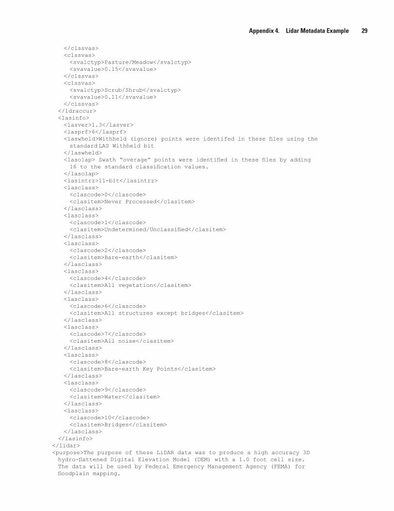
Appendix 4. Lidar Metadata Example 29
</clssvas> <clssvas> <svalctyp>Pasture/Meadow</svalctyp> <svavalue>0.15</svavalue> </clssvas> <clssvas> <svalctyp>Scrub/Shrub</svalctyp> <svavalue>0.11</svavalue> </clssvas> </ldraccur> <lasinfo> <lasver>1.3</lasver> <lasprf>6</lasprf> <laswheld>Withheld(ignore)pointswereidentifedinthesefilesusingthe standard LAS Withheld bit </laswheld> <lasolap>Swath“overage”pointswereidentifiedinthesefilesbyadding 16tothestandardclassificationvalues. </lasolap> <lasintrz>11-bit</lasintrz> <lasclass> <clascode>0</clascode> <clasitem>Never Processed</clasitem> </lasclass> <lasclass> <clascode>1</clascode> <clasitem>Undetermined/Unclassified</clasitem> </lasclass> <lasclass> <clascode>2</clascode> <clasitem>Bare-earth</clasitem> </lasclass> <lasclass> <clascode>4</clascode> <clasitem>All vegetation</clasitem> </lasclass> <lasclass> <clascode>6</clascode> <clasitem>All structures except bridges</clasitem> </lasclass> <lasclass> <clascode>7</clascode> <clasitem>All noise</clasitem> </lasclass> <lasclass> <clascode>8</clascode> <clasitem>Bare-earthKeyPoints</clasitem> </lasclass> <lasclass> <clascode>9</clascode> <clasitem>Water</clasitem> </lasclass> <lasclass> <clascode>10</clascode> <clasitem>Bridges</clasitem> </lasclass> </lasinfo> </lidar> <purpose>ThepurposeoftheseLiDARdatawastoproduceahighaccuracy3D hydro-flattenedDigitalElevationModel(DEM)witha1.0footcellsize. The data will be used by Federal Emergency Management Agency (FEMA) for floodplainmapping.

30 Lidar Base Specification Version 1.0
TheserawlidarpointclouddatawereusedtocreateclassifiedlidarLASfiles, intensityimages,3Dbreaklines,hydro-flattenedDEMsasnecessary. </purpose> <supplinf> USGSContractNo.G10PC01234 CONTRACTOR: We Map4U, Inc. SUBCONTRACTOR:AerialScanningServices,LLC Lidar data were acquired and calibrated by Aerial Scanning Services. All follow-on processing was completed by the prime contractor. </supplinf> </descript> <timeperd> <timeinfo> <rngdates> <begdate>20100216</begdate> <enddate>20100218</enddate> </rngdates> </timeinfo> <current>ground condition</current> </timeperd> <status> <progress>Partial: Lot 2 of 5</progress> <update>None planned</update> </status> <spdom> <bounding> <westbc>-91.750000</westbc> <eastbc>-91.250000</eastbc> <northbc>38.000000</northbc> <southbc>37.250000</southbc> </bounding> <lboundng> <leftbc>584800.00</leftbc> <rightbc>664800.00</rightbc> <topbc>4225400.00</topbc> <bottombc>4141400.00</bottombc> </lboundng> </spdom> <keywords> <theme> <themekt>None</themekt> <themekey>Elevationdata</themekey> <themekey>Lidar</themekey> <themekey>Hydrology</themekey> </theme> <place> <placekt>None</placekt> <placekey>Missouri</placekey> <placekey>PhelpsCounty</placekey> <placekey>DentCounty</placekey> <placekey>MarkTwainNationalForest</placekey> </place> </keywords> <accconst>No restrictions apply to this data.</accconst> <useconst>None.However,usersshouldbeawarethattemporalchangesmayhaveoccurred since this dataset was collected and that some parts of these data may no longer represent actual surface conditions. Users should not use these data for critical applicationswithoutafullawarenessofitslimitations.AcknowledgementoftheU.S. Geological Survey would be appreciated for products derived from these data. </useconst> <ptcontac> <cntinfo>

Appendix 4. Lidar Metadata Example 31
<cntorgp> <cntorg>We Map 4U, Data Acquisition Department</cntorg> <cntper>Jane Smith</cntper> </cntorgp> <cntaddr> <addrtype>mailing and physical</addrtype> <address>123MainSt.</address> <city>Anytown</city> <state>MO</state> <postal>61234</postal> <country>USA</country> </cntaddr> <cntvoice>555-555-1234</cntvoice> <cnttdd>555-555-1122</cnttdd> <cntfax>555-5550-1235</cntfax> <cntemail>[email protected]</cntemail> <hours>Monday through Friday 8:00 AM to 4:00 PM (Central Time)</hours> <cntinst>If unable to reach the contact by telephone, please send an email. You should get a response within 24 hours. </cntinst> </cntinfo> </ptcontac> <native>OptechDASHMap4.2200;ALSPostProcessor2.70Build#15; GeoCue Version 6.1.21.4; Windows XP Operating System \\server\directory path\*.LAS 17GB </native> </idinfo> <dataqual> <logic>Datacovertheentireareaspecifiedforthisproject.</logic> <complete>TheserawLASdatafilesincludealldatapointscollected. No points have been removed or excluded. A visual qualitative assessment was performed to ensure data completeness. There are no void areas or missing data. The raw point cloud is of good qualityanddatapassesFundamentalVerticalAccuracyspecifications. </complete> <posacc> <vertacc> <vertaccr>ThespecificationsrequirethatonlyFundamentalVerticalAccuracy(FVA) becomputedforrawlidarpointcloudswathfiles.Theverticalaccuracy was tested with 25 independent survey located in open terrain. These checkpointswerenotusedinthecalibrationorpostprocessingofthe lidarpointclouddata.Thesurveycheckpointsweredistributed throughouttheprojectarea.Specificationsforthisprojectrequire thattheFVAbe25cmorbetterAccuracyZat95percentconfidencelevel. </vertaccr> <qvertpa> <vertaccv>0.19metersAccuracyZat95percentConfidenceInterval</vertaccv> <vertacce>The FVA was tested using 25 independent survey located in open terrain terrain.Thesurveycheckpointsweredistributedthroughouttheprojectarea. The25independantcheckpointsweresurveyedusingxxxxtechnique.Elevations fromtheunclassifiedlidarsurfaceweremeasuredforthex,ylocationofeach checkpoint.Elevationsinterpolatedfromthelidarsurfacewerethencompared to the elevation values of the surveyed control. The RMSE was computed to be 0.097cm. AccuracyZhasbeentestedtomeet9.7cmFundamentalVerticalAccuracyat95 PercentconfidencelevelusingRMSE(z)x1.9600asdefinedbytheNational Standards for Spatial Data Accuracy (NSSDA); assessed and reported using National Digital Elevation Program (NDEP)/ASPRS Guidelines. </vertacce> </qvertpa> </vertacc>

32 Lidar Base Specification Version 1.0
</posacc> <lineage> <srcinfo> <srccite> <citeinfo> <origin>Jiffy Survey, Inc</origin> <pubdate> 20100115</pubdate> <title>Ground Control for Phelps and Dent County, MO lidar project</title> <geoform>vector digital data and tabular data</geoform> <pubinfo> <pubplace>Jiffy Survey, Inc.</pubplace> <publish>Jiffy Survey, Inc., GPS department</publish> </pubinfo> <othercit>None</othercit> <onlink>ftp://JiffySurveyftp.com/data/outgoing/Task1/</onlink> </citeinfo> </srccite> <srcscale>50</srcscale> <typesrc>CD-ROM</typesrc> <srctime> <timeinfo> <sngdate> <caldate>201001003</caldate> </sngdate> </timeinfo> <srccurr>ground condition</srccurr> </srctime> <srccitea>Phelps_Co_lidar_gnd_ctrl</srccitea> <srccontr>This data source was used (along with the airborne GPS/IMU data) to georeference the lidar point cloud data. </srccontr> </srcinfo> <srcinfo> <srccite> <citeinfo> <origin>USDA</origin> <pubdate> 20090606</pubdate> <title>NAIP Imagery for Phelps and Dent County, MO lidar project</title> <geoform>raster orthoimagery</geoform> <pubinfo> <pubplace>USGS-EROS</pubplace> <publish>USGS-EROS</publish> </pubinfo> <othercit>None</othercit> <onlink></onlink> </citeinfo> </srccite> <srcscale>50</srcscale> <typesrc>online</typesrc> <srctime> <timeinfo> <sngdate> <caldate>20090101</caldate> </sngdate> </timeinfo> <srccurr>ground condition</srccurr> </srctime> <srccitea>Phelps-Dent_Co_NAIP_Imagery</srccitea> <srccontr>This data source was used (along with the lidar intensity imagery) to classify the lidar point cloud data. </srccontr> </srcinfo>

Appendix 4. Lidar Metadata Example 33
<srcinfo> <srccite> <citeinfo> <origin>We Map 4U, Inc.</origin> <pubdate>20101208</pubdate> <title>Lidar Intensity Imagery for Phelps and Dent County, MO</title> <geoform>raster orthoimagery</geoform> <pubinfo> <pubplace>USGS-EROS</pubplace> <publish>USGS-EROS</publish> </pubinfo> <othercit>None</othercit> <onlink></onlink> </citeinfo> </srccite> <srcscale>50</srcscale> <typesrc>online</typesrc> <srctime> <timeinfo> <rngdates> <begdate>20100216</begdate> <enddate>20100218</enddate> </rngdates> </timeinfo> <srccurr>ground condition</srccurr> </srctime> <srccitea>Phelps-Dent_Co_Lidar_Intensity_Imagery</srccitea> <srccontr>This data source was used (along with NAIP imagery) to classify the lidar point cloud data. </srccontr> </srcinfo> <procstep> <procdesc>Lidar Pre-Processing: Airborne GPS and IMU data were merged to develop aSingleBestEstimate(SBET)ofthelidarsystemtrajectoryforeachlift. Lidar ranging data were initially calibrated using previous best parameters for this instrument and aircraft. Relative calibration was evaluated using advanced plane-matching analysis and parameter corrections derived. This was repeated iteratively until residual errors between overlapping swaths, acrossallprojectlifts,wasreducedto2cmorless.Datawerethenblock adjustedtomatchsurveyedcalibrationcontrol.RawdataFVAwerechecked usingindependentlysurveyedcheckpoints.Swathoveragepointswereidentified andtaggedwithineachswathfile.Theresultsofthefinalcalibration,FVA and horizontal accuracy assessments, and the “raw” swaths were forwarded totheclienttoobtainaNoticeToProceedonclassificationandderivative product generation. </procdesc> <srcused>Phelps_Co_lidar_gnd_ctrl</srcused> <procdate>20100131</procdate> <proccont> <cntinfo> <cntorgp> <cntorg>We Map 4U, Data Acquisition Department</cntorg> <cntper>Manny Puntas</cntper> </cntorgp> <cntaddr> <addrtype>mailing and physical</addrtype> <address>123MainSt.</address> <city>Anytown</city> <state>MO</state> <postal>61234</postal> <country>USA</country> </cntaddr>

34 Lidar Base Specification Version 1.0
<cntvoice>555-555-556</cntvoice> <cntfax>555-5550-1236</cntfax> <cntemail>[email protected]</cntemail> <hours>Monday through Friday 8:00 AM to 4:00 PM (Central Time)</hours> <cntinst>If unable to reach the contact by telephone, please send an email. You should get a response within 24 hours. </cntinst> </cntinfo> </proccont> </procstep> <procstep> <procdesc>Lidar Post-Processing: The calibrated and controlled lidar swathswereprocessedusingautomaticpointclassificationroutines in proprietary software. These routines operate against the entire collection (all swaths, all lifts), eliminating character differences betweenfiles.Datawerethendistributedasvirtualtilestoexperienced lidaranalystsforlocalizedautomaticclassification,manualediting, andpeer-basedQCchecks.SupervisoryQCmonitoringofworkinprogress andcompletededitingensuredconsistencyofclassificationcharacterand adherence to project requirements across the entire project area. Allclassificationtagsarestoredintheoriginalswathfiles. AftercompletionofclassificationandfinalQCapproval,theFVA, SVAs, and CVA for the project are calculated. Sample areas for each Land cover type present in the project area was extracted and forwarded to the client, along with the results of the accuracy tests. Upon acceptance, thecompleteclassifiedlidarswathfilesweredeliveredtotheclient. </procdesc> <srcused>Phelps-Dent_Co_NAIP_Imagery</srcused> <srcused>Phelps-Dent_Co_Lidar_Intensity_Imagery</srcused> <procdate>20100530</procdate> <proccont> <cntinfo> <cntorgp> <cntorg>We Map 4U, Data Acquisition Department</cntorg> <cntper>Manny Puntas</cntper> </cntorgp> <cntaddr> <addrtype>mailing and physical</addrtype> <address>123MainSt.</address> <city>Anytown</city> <state>MO</state> <postal>61234</postal> <country>USA</country> </cntaddr> <cntvoice>555-555-556</cntvoice> <cntfax>555-5550-1236</cntfax> <cntemail>[email protected]</cntemail> <hours>Monday through Friday 8:00 AM to 4:00 PM (Central Time)</hours> <cntinst>If unable to reach the contact by telephone, please send an email. You should get a response within 24 hours. </cntinst> </cntinfo> </proccont> </procstep> </lineage> </dataqual> <spdoinfo> <direct>Vector</direct> <ptvctinf> <sdtsterm> <sdtstype>Point</sdtstype> <ptvctcnt>764,567,423</ptvctcnt>

Appendix 4. Lidar Metadata Example 35
</sdtsterm> </ptvctinf> </spdoinfo> <spref> <horizsys> <planar> <gridsys> <gridsysn>Universal Transverse Mercator</gridsysn> <utm> <utmzone>15</utmzone> <transmer> <sfctrmer>0.9996</sfctrmer> <longcm>-117.000000</longcm> <latprjo>0.0</latprjo> <feast>500000</feast> <fnorth>0.0</fnorth> </transmer> </utm> </gridsys> <planci> <plance>coordinate pair</plance> <coordrep> <absres>0.01</absres> <ordres>0.01</ordres> </coordrep> <plandu>meters</plandu> </planci> </planar> <geodetic> <horizdn>NorthAmericanDatumof1983</horizdn> <ellips>Geodetic Reference System 80</ellips> <semiaxis>6378137</semiaxis> <denflat>298.257222101</denflat> </geodetic> </horizsys> <vertdef> <altsys> <altdatum>North American Vertical Datum of 1988</altdatum> <altres> 0.01</altres> <altunits>meters</altunits> <altenc>Explicit elevation coordinate included with horizontal coordinates</altenc> </altsys> </vertdef> </spref> <distinfo> <distrib> <cntinfo> <cntperp> <cntper>JimBrooks,GISP</cntper> <cntorg>Phelps-Dent Council of Government (PDCOG), GIS and Data Division</cntorg> </cntperp> <cntpos>Director</cntpos> <cntaddr> <addrtype>mailing and physical address</addrtype> <address>PDCOG, GIS Division</address> <address>123ABDStreet</address> <address> Suite 456</address> <city>Sometown</city> <state>MO</state> <postal>99999</postal> <country>USA</country> </cntaddr>

36 Lidar Base Specification Version 1.0
<cntvoice>555-555-9999</cntvoice> <cntemail>[email protected]</cntemail> </cntinfo> </distrib> <resdesc>The Phelps-Dent Council of Government (PDCOG)distributes data directly to program partners. Public access to the data is available from the USGS as listed below. </resdesc> <distliab>In no event shall the creators, custodians, or distributors of these data be liable for any damages arising out of its use, or from the inability of the customer to use these data for their intended application. </distliab> </distinfo> <metainfo> <metd> 20101206</metd> <metrd> 20101207</metrd> <metc> <cntinfo> <cntorgp> <cntorg>We Map 4U, Data Acquisition Department</cntorg> <cntper>John Smith</cntper> </cntorgp> <cntaddr> <addrtype>mailing and physical</addrtype> <address>123MainSt.</address> <city>Anytown</city> <state>MO</state> <postal>61234</postal> <country>USA</country> </cntaddr> <cntvoice>555-555-1234</cntvoice> <cnttdd>555-555-1122</cnttdd> <cntfax>555-5550-1235</cntfax> <cntemail>[email protected]</cntemail> <hours>Monday through Friday 8:00 AM to 4:00 PM (Central Time)</hours> <cntinst> If unable to reach the contact by telephone, please send an email. You should get a response within 24 hours. </cntinst> </cntinfo> </metc> <metstdn>FGDC Content Standard for Digital Geospatial Metadata</metstdn> <metstdv>FGDC-STD-001-1998</metstdv> <metac>None</metac> <metuc>None</metuc> <metsi> <metscs>None</metscs> <metsc>Unclassified</metsc> <metshd>None</metshd> </metsi> <metextns> <onlink>None</onlink> <metprof>None</metprof> </metextns> </metainfo></metadata>

Appendix 5. Lidar Metadata Template 37
Appendix 5. Lidar Metadata Template<?xml version=”1.0” encoding=”UTF-8”?><!--DOCTYPE metadata SYSTEM “fgdc-std-001-1998.dtd”--><metadata> <idinfo> <citation> <citeinfo> <origin> EXAMPLE: We Map 4U, Inc. <!--REQUIRED Element: Originator Name of the contractor that developed the dataset. Domain:“Unknown”freetext --> </origin> <pubdate> 20101208 <!--REQUIRED Element: Publication Date DatethatthedatasetwasRELEASED.ThefieldMUSTbeformattedYYYYMMDD Domain:“Unknown”“UnpublishedMaterial”YYYYMMDDfreetext --> </pubdate> <title> EXAMPLE: Lidar data for Phelps and Dent Counties, MO MO_Phelps-Dent-CO_2010 <!--REQUIRED Element: Title Thenamebywhichthedatasetisknown. If a Project ID in the following format has been issued for this project, include it in the title element [State_description_aquisition-date]. Domain: free text --> </title> <geoform> EXAMPLE: Lidar point cloud <!--REQUIRED Element: Geospatial Data Presentation Form The mode in which the geospatial data are represented. Domain: free text --> </geoform> </citeinfo> </citation> <descript> <abstract> EXAMPLE: Geographic Extent: This dataset is lidar point cloud data, which encompasses a 1,000 meter buffer around Phelps and Dent Counties in Missouri, approximatly 829 square miles. Dataset Description: This dataset consists of 457 lidar point cloud .LAS swathfiles.Each.LASfilecontainslidarpointinformation,whichhasbeen calibrated,controlled,andclassified.Eachfilerepresentsaseparate swathoflidar.Collectedswathfilesthatwerelargerthan2GBwere initiallywritteninmultiplesub-swathfiles,eachlessthan2GB. Ground Conditions: water at normal levels; no unusual innundation; no snow; leaf off <!--REQUIRED Element: Abstract A brief narrative summary of the dataset. It is desireable for the Abstract to include a consolidated summary other elementsthatareincludedelsewhereinthismetadatafile,foreaseofuse. Domain: free text --> </abstract> <lidar> <!--REQUIREDSection:forProject,Swath,andClassifiedLASmetadatafiles--> <ldrinfo> <!--REQUIRED Group: This group of tags contains metadata about the sesnor and collection conditions. -->
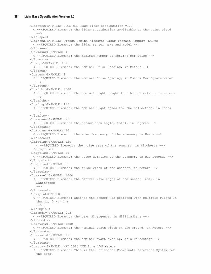
38 Lidar Base Specification Version 1.0
<ldrspec>EXAMPLE:USGS-NGPBaseLidarSpecificationv1.0 <!--REQUIREDElement:thelidarspecificationapplicabletothepointcloud --> </ldrspec> <ldrsens>EXAMPLE: Optech Gemini Airborne Laser Terrain Mappers (ALTM) <!--REQUIREDElement:thelidarsensormakeandmodel--> </ldrsens> <ldrmaxnr>EXAMPLE: 4 <!--REQUIRED Element: the maximum number of returns per pulse --> </ldrmaxnr> <ldrnps>EXAMPLE: 1.2 <!--REQUIRED Element: the Nominal Pulse Spacing, in Meters --> </ldrnps> <ldrdens>EXAMPLE: 2 <!--REQUIRED Element: the Nominal Pulse Spacing, in Points Per Square Meter --> </ldrdens> <ldrfltht>EXAMPLE:3000 <!--REQUIREDElement:thenominalflightheightforthecollection,inMeters --> </ldrfltht> <ldrfltsp>EXAMPLE:115 <!--REQUIREDElement:thenominalflightspeedforthecollection,inKnots --> </ldrfltsp> <ldrscana>EXAMPLE: 26 <!--REQUIRED Element: the sensor scan angle, total, in Degrees --> </ldrscana> <ldrscanr>EXAMPLE: 40 <!--REQUIREDElement:thescanfrequencyofthescanner,inHertz--> </ldrscanr> <ldrpulsr>EXAMPLE: 120 <!--REQUIREDElement:thepulserateofthescanner,inKilohertz--> </ldrpulsr> <ldrpulsd>EXAMPLE: 10 <!--REQUIRED Element: the pulse duration of the scanner, in Naonseconds --> </ldrpulsd> <ldrpulsw>EXAMPLE:3 <!--REQUIRED Element: the pulse width of the scanner, in Meters --> </ldrpulsw> <ldrwavel>EXAMPLE: 1064 <!--REQUIRED Element: the central wavelength of the sensor laser, in Nanometers --> </ldrwavel> <ldrmpia>EXAMPLE: 0 <!--REQUIRED Element: Whether the sensor was operated with Multiple Pulses In The Air, 0=No; 1=Y --> </ldrmpia > <ldrbmdiv>EXAMPLE:0.3 <!--REQUIRED Element: the beam divergence, in Milliradians --> </ldrbmdiv> <ldrswatw>EXAMPLE: 1200 <!--REQUIRED Element: the nominal swath width on the ground, in Meters --> </ldrswatw> <ldrswato>EXAMPLE: 15 <!--REQUIRED Element: the nominal swath overlap, as a Percentage --> </ldrswato> <ldrcrs>EXAMPLE:NAD_1983_UTM_Zone_15N_Meters <!--REQUIREDElement:ThisistheHorizontalCoordinateReferenceSystemfor the data.
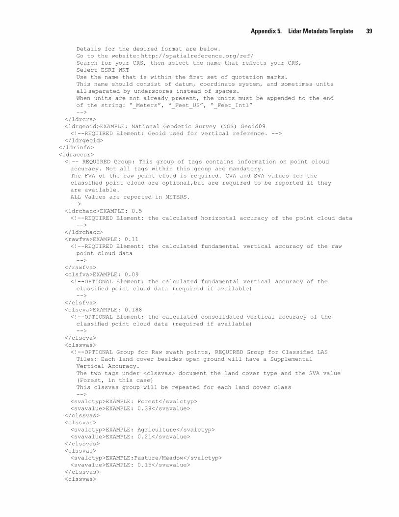
Appendix 5. Lidar Metadata Template 39
Details for the desired format are below. Go to the website: http://spatialreference.org/ref/ SearchforyourCRS,thenselectthenamethatreflectsyourCRS, SelectESRIWKT Usethenamethatiswithinthefirstsetofquotationmarks. This name should consist of datum, coordinate system, and sometimes units all separated by underscores instead of spaces. When units are not already present, the units must be appended to the end of the string: “_Meters”, “_Feet_US”, “_Feet_Intl” --> </ldrcrs> <ldrgeoid>EXAMPLE: National Geodetic Survey (NGS) Geoid09 <!--REQUIRED Element: Geoid used for vertical reference. --> </ldrgeoid> </ldrinfo> <ldraccur> <!-- REQUIRED Group: This group of tags contains information on point cloud accuracy. Not all tags within this group are mandatory. The FVA of the raw point cloud is required. CVA and SVA values for the classifiedpointcloudareoptional,butarerequiredtobereportedifthey are available. ALL Values are reported in METERS. --> <ldrchacc>EXAMPLE: 0.5 <!--REQUIRED Element: the calculated horizontal accuracy of the point cloud data --> </ldrchacc> <rawfva>EXAMPLE: 0.11 <!--REQUIRED Element: the calculated fundamental vertical accuracy of the raw point cloud data --> </rawfva> <clsfva>EXAMPLE: 0.09 <!--OPTIONAL Element: the calculated fundamental vertical accuracy of the classifiedpointclouddata(requiredifavailable) --> </clsfva> <clscva>EXAMPLE: 0.188 <!--OPTIONAL Element: the calculated consolidated vertical accuracy of the classifiedpointclouddata(requiredifavailable) --> </clscva> <clssvas> <!--OPTIONALGroupforRawswathpoints,REQUIREDGroupforClassifiedLAS Tiles: Each land cover besides open ground will have a Supplemental Vertical Accuracy. The two tags under <clssvas> document the land cover type and the SVA value (Forest, in this case) This clssvas group will be repeated for each land cover class --> <svalctyp>EXAMPLE: Forest</svalctyp> <svavalue>EXAMPLE:0.38</svavalue> </clssvas> <clssvas> <svalctyp>EXAMPLE: Agriculture</svalctyp> <svavalue>EXAMPLE: 0.21</svavalue> </clssvas> <clssvas> <svalctyp>EXAMPLE:Pasture/Meadow</svalctyp> <svavalue>EXAMPLE: 0.15</svavalue> </clssvas> <clssvas>
40 Lidar Base Specification Version 1.0
<svalctyp>EXAMPLE: Scrub/Shrub</svalctyp> <svavalue>EXAMPLE: 0.11</svavalue> </clssvas> <clssvas> <svalctyp>EXAMPLE: Urban</svalctyp> <svavalue>EXAMPLE:0.13</svavalue> </clssvas> </ldraccur> <lasinfo> <!-- REQUIRED Group: This group of tags contains information on the LAS version andclassificationvaluesforthepointcloud. --> <lasver>EXAMPLE:1.3 <!-- REQUIRED Element: The version of the LAS Standard applicable to this data set. --> </lasver> <lasprf>EXAMPLE: 6 <!-- REQUIRED Element: The Point Data Record Format used for the point cloud. --> </lasprf> <laswheld>EXAMPLE:Withheld(ignore)pointswereidentifedinthesefilesusing the standard LAS Withheld bit. <!--REQUIREDElement:Describehowwithheldpointsareidentified.--> </laswheld> <lasolap>EXAMPLE:Swath“overage”pointswereidentifiedinthesefilesby adding16tothestandardclassificationvalues. <!--REQUIREDElement:Thisdescribeshowoveragepointsareidentified.--> </lasolap> <lasintr>EXAMPLE: 11 <!--REQUIREDElement:Thisspecifiestheradiometricresolutionofintensity values,inBits. --> </lasintr> <lasclass> <!--REQUIREDSectionifLASdataareclassified:Eachlasclasssection provides a code value and a description for that code. --> <clascode>EXAMPLE: 0</clascode> <clasitem>EXAMPLE: Never Processed</clasitem> </lasclass> <lasclass> <clascode>EXAMPLE: 1</clascode> <clasitem>EXAMPLE:Undetermined/Unclassified</clasitem> </lasclass> <lasclass> <clascode>EXAMPLE: 2</clascode> <clasitem>EXAMPLE:Bare-earth</clasitem> </lasclass> <lasclass> <clascode>EXAMPLE: 4</clascode> <clasitem>EXAMPLE: All vegetation</clasitem> </lasclass> <lasclass> <clascode>EXAMPLE: 6</clascode> <clasitem>EXAMPLE: All structures except bridges</clasitem> </lasclass> <lasclass> <clascode>EXAMPLE: 7</clascode> <clasitem>EXAMPLE: All noise</clasitem> </lasclass> <lasclass>
Appendix 5. Lidar Metadata Template 41
<clascode>EXAMPLE: 8</clascode> <clasitem>EXAMPLE:Bare-earthKeyPoints</clasitem> </lasclass> <lasclass> <clascode>EXAMPLE: 9</clascode> <clasitem>EXAMPLE: Water</clasitem> </lasclass> <lasclass> <clascode>EXAMPLE: 10</clascode> <clasitem>EXAMPLE:Bridges</clasitem> </lasclass> </lasinfo> </lidar> <purpose>Thepurposeoftheselidardatawastoproducehighaccuracy3D hydro-flattenedDigitalElevationModel(DEM)witha1.0footcellsize. ThedatawillbeusedbyFEMAforflood-plainmapping. TheserawlidarpointclouddatawereusedtocreateclassifiedlidarLASfiles, intensityimages,3Dbreaklines,hydro-flattenedDEMsasnecessary. <!--REQUIRED Element: Purpose Why was the dataset was created? For what applications? Whatotherproductsthisdatasetwillbeusedtocreate:tiledclassifiedLAS, DEM, and others, required deliverables, or interim products necessary to complete the project. What scales are appropriate or inappropriate for use? Domain: free text --> </purpose> <supplinf> USGSContractNo.G10PC01234 CONTRACTOR: We Map4U, Inc. SUBCONTRACTOR:AerialScanningServices,LLC Lidar data were acquired and calibrated by Aerial Scanning Services. All follow-on processing was completed by the prime contractor. <!--OPTIONAL Element: Supplemental Information Enter other descriptive information about the dataset. Desirableinformationincludesanydeviationsfromprojectspecificationsand reasons.Italsomayincludeanyotherinformationthatthecontractorfinds necessary or useful, such as contract number or summary of lidar technology. Remove this tag or clear the contents of this tag if none. Domain: free text --> </supplinf> </descript> <timeperd> <timeinfo> <!--REQUIRED Group: Time info: will be either: single date, OR multiple dates, OR a range of dates. Examples are provided for all three formats. Delete the ones that do not apply. --> <sngdate> <!--BegintheexampleofSingleDate--> <caldate> 20100216 <!--REQUIRED Element: Calendar Date This is the date of the LiDAR collection, if the collection wascompletedinoneday.
 ThefieldMUSTbeformattedYYYYMMDD --> </caldate> </sngdate> <mdattim>

42 Lidar Base Specification Version 1.0
<!--Beginexampleofamultipledates--> <sngdate> <caldate> 20100216 <!--REQUIRED Element: Calendar Date ThisisthefirstdateoftheLiDARcollection,when multiplecollectiondatesarespecified. ThefieldMUSTbeformattedYYYYMMDD --> </caldate> </sngdate> <sngdate> <caldate> 20100218 <!--REQUIRED Element: Calendar Date This is the second date of the LiDAR collection, when multiplecollectiondatesarespecified. ThefieldMUSTbeformattedYYYYMMDD REPEAT the sngdate and caldate tags for each collection date --> </caldate> </sngdate> </mdattim> <rngdates> <!--Beginexampleofadaterange--> <begdate> 20100216 <!--REQUIREDElement:BeginningDate This is the beginning date of LiDAR collection. ThefieldMUSTbeformattedYYYYMMDD --> </begdate> <enddate> 20100218 <!--REQUIRED Element: Ending Date This is the ending date of LiDAR collection. ThefieldMUSTbeformattedYYYYMMDD --> </enddate> </rngdates> </timeinfo> <current> EXAMPLE: ground condition <!--REQUIRED Element: Currrentness Reference Enter the basis on which the time period of content information is determined. Domain: “ground condition” “publication date” free text --> </current> </timeperd> <status> <progress> EXAMPLE: Partial: Lot 2 of 5 <!--REQUIRED ELEMENT: Progress Enter the state of the dataset. Domain: “Complete” “Partial: Lot x of n” --> </progress> <update> EXAMPLE: None planned <!--REQUIRED ELEMENT: Maintenance and Update Frequency Enter the repeat cycle for the project. Domain:“Annually”“Unknown”“Noneplanned”freetext --> </update> </status> <spdom> <bounding> <westbc> -91.750000 <!--REQUIREDElement:WestBoundingCoordinate

Appendix 5. Lidar Metadata Template 43
This value is the Western-most limit of coverage of the dataset expressed as longitude. This value will be negative in the United States. This value MUST be expressed in Decimal Degrees. Domain:-180.0<=WestBoundingCoordinate<180.0 --> </westbc> <eastbc> -91.25000 <!--REQUIREDElement:EastBoundingCoordinate This value is the Eastern-most limit of coverage of the dataset expressed as longitude. This value will be negative in the United States. This value MUST be expressed in Decimal Degrees. Domain:-180.0<=EastBoundingCoordinate<=180.0 --> </eastbc> <northbc>38.00000 <!--REQUIREDElement:NorthBoundingCoordinate This value is the Northern-most limit of coverage of the dataset expressed as latitude. This value will be positive in the United States. This value MUST be expressed in Decimal Degrees. Domain:-90.0<=NorthBoundingCoordinate<=90.0 --> </northbc> <southbc>37.250000 <!--REQUIREDElement:SouthBoundingCoordinate This value is the Southern-most limit of coverage of the dataset expressed as latitude. This value will be positive in the United States. This value MUST be expressed in Decimal Degrees. Domain:-90.0<=SouthBoundingCoordinate<=90.0 --> </southbc> </bounding> <lboundng> <leftbc> 584800 <!--REQUIRED Element: This value is the Western-most coordinate of limit of coverage of the dataset expressed in the Coordinate Reference System in which the data are delivered. --> </leftbc> <rightbc> 664800 <!--REQUIRED Element: This value is the Eastern-most coordinate of limit of coverage of the dataset expressed in the Coordinate Reference System in which the data are delivered. --> </rightbc> <topbc> 4225400 <!--REQUIRED Element: This value is the Northern-most coordinate of limit of coverage of the dataset expressed in the Coordinate Reference System in which the data are delivered. --> </topbc> <bottombc> 4141400 <!--REQUIRED Element: This value is the Southern-most coordinate of limit of coverage of the dataset expressed in the Coordinate Reference System in which the data are delivered. --> </bottombc> </lboundng> </spdom>

44 Lidar Base Specification Version 1.0
<keywords> <theme> <themekt>EXAMPLE:None <!--REQUIREDElement:ThemeKeywordThesaurus A formally registered thesaurus or a similar authoritative source of theme keywords. Domain: “None” free text --> </themekt> <themekey>EXAMPLE:Elevationdata <!--REQUIREDElement:ThemeKeyword:Elevationdata(required)--> </themekey> <themekey>EXAMPLE:Lidar <!--REQUIREDElement:ThemeKeyword:Lidar(required)--> </themekey> <themekey>EXAMPLE:Hydrology <!--Enteranyadditionalapplicablethemekeywords,useonlyONEkeywordforeach themekeytag.Repeatthethemekeytagasmanytimesasnecessary. Domain: free text --> </themekey> </theme> <place> <placekt>EXAMPLE:None <!--REQUIREDElement:PlaceKeywordThesaurus Reference to a formally registered thesaurus or a similar authoritative sourceofplacekeywords. Domain: “None” “Geographic Names Information System” free text --> </placekt> <placekey>EXAMPLE:Missouri <!--REQUIREDElement:PlaceKeyword Formulti-stateprojects,makeaseparateentryforeachstate. Listonlyonestateforeachplacekeytag. --> </placekey> <placekey>EXAMPLE:PhelpsCounty <!--REQUIREDElement:PlaceKeyword Formulti-countyprojects,makeaseparateentryforeachcounty. Listonlyonecountyforeachplacekeytag. --> </placekey> <placekey>EXAMPLE:DentCounty </placekey> <placekey>EXAMPLE:MarkTwainNationalForest <!--Enteranyadditionalapplicableplacekeywords,forexamplecitiesor landmarks. Useonlyonekeywordforeachplacekeytag. Repeattheplacekeytagasmanytimesasnecessary. Domain: free text --> </placekey> </place> </keywords> <accconst> EXAMPLE: No restrictions apply to these data. <!--REQUIRED Element: Access Constraints. Enter restrictions and legal prerequisites for accessing the dataset. These include any access constraints applied to assure the protection of privacy or intellectual property, and any special restrictions or limitations on obtaining the dataset. Domain: “None” free text -->
Appendix 5. Lidar Metadata Template 45
</accconst> <useconst>EXAMPLE:None.However,usersshouldbeawarethattemporalchangesmay have occurred since this dataset was collected and that some parts of these data may no Longer represent actual surface conditions. Users should not use these data for criticalapplicationswithoutafullawarenessofit’slimitations. Acknowledgement of the U.S. Geological Survey would be appreciated for products derived from these data. <!--REQUIRED Element: Enter restrictions and legal prerequisites for using the dataset after access is granted. These include any use constraints applied to assure the protection of privacy or intellectual property, and any special restrictions or limitations on using the dataset. Domain: “None” free text --> </useconst> <ptcontac> <cntinfo> <cntorgp> <cntorg> EXAMPLE: We Map 4U, Data Acquisition Department <!--REQUIRED Element: Contact Organization: Nameoftheorganizationthatcreatedthedataandisknowledgeableabout the data. Domain: free text --> </cntorg> <cntper> EXAMPLE: Jane Smith <!--REQUIRED Element: Contact Person Thenameoftheindividualwhoisknowledgeableaboutthedata. Domain: free text --> </cntper> </cntorgp> <cntaddr> <addrtype> EXAMPLE: mailing and physical <!--REQUIRED Element: Address Type The type of address that follows. Only required for “mailing” or “mailing and physical”. If the contractor has a different mailing and physical address, the physical address does not need to be included. This section may be repeated if you would liketoprovideaseparatephysicaladdress. Domain: “mailing” “physical” “mailing and physical”, free text --> </addrtype> <address>EXAMPLE:123MainSt. <!--REQUIRED Element: Address The address of the contractor. For multiple line addresses the address tag may be repeated as many times as needed. Domain: free text --> </address> <city> EXAMPLE: Anytown <!--REQUIRED Element: City The city of the address. Domain: free text --> </city> <state> EXAMPLE: MO <!--REQUIRED Element: State The state or province of the address. Domain: free text --> </state>

46 Lidar Base Specification Version 1.0
<postal>EXAMPLE:61234 <!--REQUIRED Element: Postal Code EntertheZIPorotherpostalcodeoftheaddress. Domain: free text --> </postal> <country> EXAMPLE: USA <!--OPTIONAL Element: Country The country of the address. Domain: free text --> </country> </cntaddr> <cntvoice>EXAMPLE:555-555-1234 <!--REQUIRED Element: Contact Voice Telephone Thetelephonenumberbywhichindividualscanspeaktothe organization or individual responsible for the data. Domain: free text --> </cntvoice> <cnttdd> EXAMPLE: 555-555-1122 <!--OPTIONAL Element: Contact TDD/TTY Telephone The telephone number by which hearing-impaired individuals can contact the organization or individual. Domain: free text --> </cnttdd> <cntfax>EXAMPLE:555-5550-1235 <!--OPTIONAL Element: Contact Fax The telephone number of a facsimile machine of the organization or individual. Domain: free text --> </cntfax> <cntemail> EXAMPLE: [email protected] <!--OPTIONAL Element: Contact E-mail Address The email address of the organization or individual. Domain: free text --> </cntemail> <hours> EXAMPLE: Monday through Friday 8:00 AM to 4:00 PM (Central Time) <!--OPTIONALElement:HoursofService Thetimeperiodwhenindividualscanspeaktotheorganizationorindividual. Domain: free text --> </hours> <cntinst> EXAMPLE: If unable to reach the contact by telephone, please send an email. You should get a response within 24 hours. <!--OPTIONAL Element: Contact Instructions Supplemental instructions on how or when to contact the individual or organization. Domain: free text --> </cntinst> </cntinfo> </ptcontac> <native>EXAMPLE:OptechDASHMap4.2200;ALSPostProcessor2.70Build#15; GeoCue Version 6.1.21.4; Windows XP Operating System \\server\directory path\*.LAS 17GB <!--REQUIRED: Native Data Set Environment Description of the dataset in the producer’s processing

Appendix 5. Lidar Metadata Template 47
environment, including items such as the name of the software (including version), thecomputeroperatingsystem,filename(includinghost-,path-,andfilenames), and the dataset size. Domain: free text --> </native> </idinfo> <dataqual> <logic>EXAMPLE:Datacovertheentireareaspecifiedforthisproject. <!--REQUIRED Element: Logical Consistency Report Describethefidelityofrelationsinthedata structure of the lidar data: tests of valid values or topological tests. Identify software used and the date of the tests. Domain: free text --> </logic> <complete>EXAMPLE:TheserawLASdatafilesincludealldatapointscollected. No points have been removed or excluded. A visual qualitative assessment was performed to ensure data completeness. There are no void areas or missing data. The raw point cloud is of good qualityanddatapassesFundamentalVerticalAccuracyspecifications. <!--REQUIRED Element: Completeness Report Document the inclusion or omissions of features for the dataset. Minimum width or area thresholds. Selection criteria or other rules used to derive the dataset. Domain: free text --> </complete> <posacc> <vertacc> <vertaccr>EXAMPLE:ThespecificationsrequirethatonlyFundamentalVertical Accuracy(FVA)becomputedforrawlidarpointcloudswathfiles. The vertical accuracy was tested with 25 independent survey located in open terrain.Thesecheckpointswerenotusedinthecalibrationorpost processingofthelidarpointclouddata.Thesurveycheckpointswere distributedthroughouttheprojectarea.Specificationsforthisproject requirethattheFVAbe25cmorbetterAccuracyZat95percentconfidence level. <!--REQUIRED Element: Vertical Positional Accuracy Report An explanation of the accuracy of the vertical coordinate measurements and a description of the tests used. Domain: free text --> </vertaccr> <qvertpa> <vertaccv>EXAMPLE:0.19metersAccuracyZat95percentConfidenceInterval <!--REQUIRED Element: Vertical Positional Accuracy Value Vertical accuracy expressed in (ground) meters. ClearlystatewhetherthisvalueisRMSEzorAccuracyZ Domain: free text --> </vertaccv> <vertacce> The FVA was tested using 25 independent survey located in open terrainterrain.Thesurveycheckpointsweredistributedthroughoutthe projectarea.The25independantcheckpointsweresurveyedusingxxxx technique.Elevationsfromtheunclassifiedlidarsurfaceweremeasured forthex,ylocationofeachcheckpoint. Elevations interpolated from the lidar surface were then compared to the elevation values of the surveyed control. The RMSE was computed to be 0.097m.AccuracyZhasbeentestedtomeet9.7cmFundamentalVertical

48 Lidar Base Specification Version 1.0
Accuracyat95PercentconfidencelevelusingRMSE(z)x1.9600asdefined by the National Standards for Spatial Data Accuracy (NSSDA); assessed and reported using National Digital Elevation Program (NDEP)/ASRPS Guidelines. <!--REQUIRED Element: Vertical Positional Accuracy Explanation IdentificationofthetestthatyieldedtheVerticalPositionalAccuracy Value. Domain: free text --> </vertacce> </qvertpa> </vertacc> </posacc> <lineage> <srcinfo> <!-- The srcinfo section of the metadata MUST be repeated for each data source thatcontributedmakingthisunclassifiedLASswathdataset.Thisincludes, but is not limited to, 1) ground control used for calibrating the lidar data, 2)theactuallidaraquistiondata,and3)independentgroundcontrolusedto assess the accuracy of the lidar point cloud. --> <srccite> <citeinfo> <origin> EXAMPLE: Jiffy Survey, Inc <!--REQUIRED Element: Originator This the name of an organization or individual that developed the dataset. If the creation of this data source was created by a subcontractor, the subcontractors name and contact information should be entered as the source for that contributing data set. Domain:“Unknown”freetext --> </origin> <pubdate> 20100115 <!--REQUIRED element: Date of Publication Enter the date when the dataset is published or otherwise made available for release. The format of this date must be YYYMMDD. Domain:“Unknown”“Unpublishedmaterial”freedate --> </pubdate> <title> EXAMPLE: Ground Control for Phelps and Dent County, MO lidar project <!--REQUIRED Element: Title Thenamebywhichthefirstcontributingdatasetisknown. Domain: free text --> </title> <geoform> EXAMPLE: vector digital data and tabular data <!--OPTIONAL Element: Enter the mode in which the geospatial data are represented. Domain: (the listed domain is partially from pp. 88-91 in Anglo-American Committee on Cataloguing of Cartographic Materials, 1982, Cartographic materials: A manual of interpretation for AACR2: Chicago, American Library Association): “atlas” “audio” “diagram” “document” “globe” “map” “model” “multimedia presentation”“profile”“rasterdigitaldata”“remote-sensingimage” “section” “spreadsheet” “tabular digital data” “vector digital data” “video” “view” free text --> </geoform> <pubinfo> <pubplace> EXAMPLE: Jiffy Survey, Inc. <!--REQUIRED Element: Publication Place The name of the city (and state or province, and country, if needed to

Appendix 5. Lidar Metadata Template 49
identify the city) the originator of the dataset. Domain: free text --> </pubplace> <publish> EXAMPLE: Jiffy Survey, Inc., GPS department <!--Enter the name of the individual or organization that published the dataset. Domain: free text --> </publish> </pubinfo> <othercit> EXAMPLE: None. <!--OPTIONAL Element: Other Citation Details Other information required to complete the citation. Domain: free text --> </othercit> <onlink>EXAMPLE: ftp://JiffySurveyftp.com/data/outgoing/Task1/ <!--OPTIONALElement:OnlineLinkage IFAPPLICABLE:TheURLofanonlinecomputerresourcethatcontainsthe dataset. Domain: free text --> </onlink> </citeinfo> </srccite> <srcscale> Example: 50 <!--OPTIONAL Element: Source Scale Denominator IFAPPLICABLE:Thedenominatoroftherepresentativefractiononamap (for example, on a 1:24,000-scale map, the Source Scale Denominator is 24000). Domain: Source Scale Denominator > 1 --> </srcscale> <typesrc> EXAMPLE: CD-ROM <!--REQUIRED Element: Type of Source Media Themediumofthefirstsourcedataset. Domain:“paper”“stable-basematerial”“microfiche”“microfilm” “audiocassette”“chart”“filmstrip”“transparency”“videocassette” “videodisc” “videotape” “physical model” “computer program” “disc” “cartridge tape” “magnetic tape” “online” “CD-ROM” “electronic bulletin board” “electronic mail system” free text --> </typesrc> <srctime> <timeinfo> <sngdate> <caldate>201001003 <!--REQUIRED Element: Calendar Date Thisisthedateofthefirstsourcedatasetwascreated. ThefieldMUSTbeformattedYYYYMMDD --> </caldate> </sngdate> </timeinfo> <srccurr> EXAMPLE: ground condition <!--REQUIRED Elemenet: Source Currentness Reference The basis on which the source time period of content information of the source dataset is determined. Domain: “ground condition” “publication date” free text --> </srccurr> </srctime>
50 Lidar Base Specification Version 1.0
<srccitea> EXAMPLE: Phelps_Co_lidar_gnd_ctrl <!--REQUIRED Element: Source Citation Abbreviation Enter short-form alias for the source citation. EachsourceMUSTHAVEAUNIQUEID. This ID will be used to reference these source data in the Process Step sections below. Domain: free text --> </srccitea> <srccontr> EXAMPLE: This data source was used (along with the airborne GPS/IMU Data) to georeferencing of the lidar point cloud data. <!--REQUIRED Element: Source Contribution Briefstatementidentifyingtheinformationcontributed. Domain: free text --> </srccontr> </srcinfo> <srcinfo> <srccite> <citeinfo> <origin>USDA</origin> <pubdate> 20090606</pubdate> <title>NAIP Imagery for Phelps and Dent County, MO lidar project</title> <geoform>raster orthoimagery</geoform> <pubinfo> <pubplace>USGS-EROS</pubplace> <publish>USGS-EROS</publish> </pubinfo> <othercit>None</othercit> <onlink></onlink> </citeinfo> </srccite> <srcscale>50</srcscale> <typesrc>online</typesrc> <srctime> <timeinfo> <sngdate> <caldate>20090101</caldate> </sngdate> </timeinfo> <srccurr>ground condition</srccurr> </srctime> <srccitea>Phelps-Dent_Co_NAIP_Imagery</srccitea> <srccontr>This data source was used (along with the lidar intensity imagery) to classify the lidar point cloud data. </srccontr> </srcinfo> <srcinfo> <srccite> <citeinfo> <origin>We Map 4U, Inc.</origin> <pubdate>20101208</pubdate> <title>Lidar Intensity Imagery for Phelps and Dent County, MO</title> <geoform>raster orthoimagery</geoform> <pubinfo> <pubplace>USGS-EROS</pubplace> <publish>USGS-EROS</publish> </pubinfo> <othercit>None</othercit> <onlink></onlink> </citeinfo> </srccite>

Appendix 5. Lidar Metadata Template 51
<srcscale>50</srcscale> <typesrc>online</typesrc> <srctime> <timeinfo> <rngdates> <begdate>20100216</begdate> <enddate>20100218</enddate> </rngdates> </timeinfo> <srccurr>ground condition</srccurr> </srctime> <srccitea>Phelps-Dent_Co_Lidar_Intensity_Imagery</srccitea> <srccontr>This data source was used (along with NAIP imagery) to classify the lidar point cloud data. </srccontr> </srcinfo> <procstep> <procdesc> EXAMPLE: Lidar Pre-Processing: Airborne GPS and IMU data were merged todevelopaSingleBestEstimate(SBET)ofthelidarsystemtrajectoryfor each lift. Lidar ranging data were initially calibrated using previous best parameters for this instrument and aircraft. Relative calibration was evaluated using advanced plane-matching analysis and parameter corrections derived. This was repeated iteratively until residual errors between overlapping swaths, acrossallprojectlifts,wasreducedto2cmorless.Datawerethenblock adjustedtomatchsurveyedcalibrationcontrol.RawdataFVAwerechecked usingindependentlysurveyedcheckpoints.Swathoveragepointswereidentified andtaggedwithineachswathfile.Theresultsofthefinalcalibration,FVA and horizontal accuracy assessments, and the “raw” swaths were forwarded totheclienttoobtainaNoticeToProceedonclassification andderivative product generation. <!--Enter an explanation of the event and related parameters or tolerances. Domain: free text --> </procdesc> <srcused> EXAMPLE: Phelps_Co_lidar_gnd_ctrl <!--Enter the Source Citation Abbreviation of a dataset used in the processing step. Domain: Source Citation Abbreviations from the Source Information entries for the dataset. --> </srcused> <procdate>20100131 <!--Enter the date when the event was completed. Domain:“Unknown”“Notcomplete”freedate --> </procdate> <srcprod>EXAMPLE:LiDARdatasetswithUSGSclassifications <!--Enter the Source Citation Abbreviation of an intermediate dataset that (1)issignificantintheopinionofthedataproducer,(2)isgeneratedin theprocessingstep,and(3)isusedinlaterprocessingsteps. Domain: Source Citation Abbreviations from the Source Information entries for the dataset. --> </srcprod> <proccont> <cntinfo> <cntorgp> <cntorg> EXAMPLE: We Map 4U, Data Acquisition Department <!--Enter the name of the organization to which the contact type applies. Domain: free text --> </cntorg>

52 Lidar Base Specification Version 1.0
<cntper> EXAMPLE: Manny Puntas <!--Enter the name of the individual to which the contact type applies. Domain: free text --> </cntper> </cntorgp> <cntaddr> <addrtype>mailing and physical</addrtype> <address>123MainSt.</address> <city>Anytown</city> <state>MO</state> <postal>61234</postal> <country>USA</country> </cntaddr> <cntvoice>555-555-556</cntvoice> <cntfax>555-5550-1236</cntfax> <cntemail>[email protected]</cntemail> <hours>Monday through Friday 8:00 AM to 4:00 PM (Central Time)</hours> <cntinst> If unable to reach the contact by telephone, please send an email. You should get a response within 24 hours. </cntinst> </cntinfo> </proccont> </procstep> <procstep> <procdesc>Lidar Post-Processing: The calibrated and controlled lidar swathswereprocessedusingautomaticpointclassificationroutines in proprietary software. These routines operate against the entire collection (all swaths, all lifts), eliminating character differences betweenfiles.Datawerethendistributedasvirtualtilestoexperienced lidaranalystsforlocalizedautomaticclassification,manualediting, andpeer-basedQCchecks.SupervisoryQCmonitoringofworkinprogress andcompletededitingensuredconsistencyofclassificationcharacterand adherence to project requirements across the entire project area. Allclassificationtagsarestoredintheoriginalswathfiles. AftercompletionofclassificationandfinalQCapproval,theFVA, SVAs, and CVA for the project are calculated. Sample areas for each land cover type present in the project area were extracted and forwarded to the client, along with the results of the accuracy tests. Upon acceptance, thecompleteclassifiedlidarswathfilesweredeliveredtotheclient. </procdesc> <srcused>Phelps-Dent_Co_NAIP_Imagery</srcused> <srcused>Phelps-Dent_Co_Lidar_Intensity_Imagery</srcused> <procdate>20100530</procdate> <proccont> <cntinfo> <cntorgp> <cntorg>We Map 4U, Data Acquisition Department</cntorg> <cntper>Manny Puntas</cntper> </cntorgp> <cntaddr> <addrtype>mailing and physical</addrtype> <address>123MainSt.</address> <city>Anytown</city> <state>MO</state> <postal>61234</postal> <country>USA</country> </cntaddr> <cntvoice>555-555-556</cntvoice> <cntfax>555-5550-1236</cntfax> <cntemail>[email protected]</cntemail> <hours>Monday through Friday 8:00 AM to 4:00 PM (Central Time)</hours>
Appendix 5. Lidar Metadata Template 53
<cntinst> If unable to reach the contact by telephone, please send an email. You should get a response within 24 hours. </cntinst> </cntinfo> </proccont> </procstep> </lineage> </dataqual> <spdoinfo> <direct> EXAMPLE: Vector <!--REQUIRED Element: Enter the system of objects used to represent space in the dataset. Domain: “Point” “Vector” “Raster” --> </direct> <ptvctinf> <sdtsterm> <sdtstype> EXAMPLE: Point <!--REQUIRED Element: SDTS Point and Vector Object Type Enter name of point and vector spatial objects used to l ocate zero-, one-, and two-dimensional spatial locations in the dataset. Domain: (The domain is from “Spatial Data Concepts,” which is Chapter 2 of Part 1 in Department of Commerce, 1992, Spatial Data Transfer Standard (SDTS)(FederalInformationProcessingStandard173):Washington, Department of Commerce, National Institute of Standards and Technology): “Point” “Entity point” “Label point” “Area point” “Node, planar graph” “Node,network”“String”“Link”“Completechain”“Areachain” “Networkchain,planargraph”“Networkchain,nonplanargraph” “Circulararc,threepointcenter”“Ellipticalarc”“UniformB-spline” “PiecewiseBezier”“Ringwithmixedcomposition” “Ring composed of strings” “Ring composed of chains” “Ring composed of arcs” “G-polygon” “GT-polygon composed of rings” “GT-polygon composed of chains” “Universe polygon composed of rings” “Universe polygon composed of chains” “Void polygon composed of rings” “Void polygon composed of chains” --> </sdtstype> <ptvctcnt>EXAMPLE:764,567,423 <!--OPTIONAL Element: Point and Vector Count Enter the total number of the point or vector object type occurring in the dataset. Domain: Point and Vector Object Count > 0 --> </ptvctcnt> </sdtsterm> </ptvctinf> </spdoinfo> <spref> <horizsys> <planar> <gridsys> <!--REQUIREDSection:Thesectionshouldbefilledoutwiththerelevant parameters for the coordinate reference system for the data. Usually it will beUTMoraStatePlaneZone.Deletetheirrelevantsectionbelow. --> <gridsysn> EXAMPLE: Universal Transverse Mercator <!--Enter name of the grid coordinate system. Domain: “Universal Transverse Mercator” “Universal Polar Stereographic” “StatePlaneCoordinateSystem1927”“StatePlaneCoordinateSystem1983” “ARC Coordinate System” “other grid system”

54 Lidar Base Specification Version 1.0
--> </gridsysn> <utm> <utmzone> EXAMPLE: 15 <!--EntertheidentifierfortheUTMzone. Type: integer Domain: 1<=UTMZoneNumber<=60forthenorthernhemisphere; -60<=UTMZoneNumber<=-1forthesouthernhemisphere --> </utmzone> <transmer> <sfctrmer>0.9996 <!--Enter a multiplier for reducing a distance obtained from a map by computation or scaling to the actual distance along the Central Meridian. Domain: Scale Factor at Central Meridian > 0.0 --> </sfctrmer> <longcm>-117.000000 <!--Enter the line of longitude at the center of a map projection generally used as the basis for constructing the projection. Type: real Domain: -180.0 <= Longitude of Central Meridian < 180.0 --> </longcm> <latprjo>0.0 <!--Enter latitude chosen as the origin of rectangular coordinates for a map projection. Domain: -90.0 <= Latitude of Projection Origin <= 90.0 --> </latprjo> <feast>500000 <!--Enter the value added to all “x” values in the rectangular coordinates for a map projection. This value frequently is assigned to eliminate negative numbers. ExpressedintheunitofmeasureidentifiedinPlanarCoordinateUnits. Domain: free real --> </feast> <fnorth>0.0 <!--Enter the value added to all “y” values in the rectangular coordinates for a map projection. This value frequently is assigned to eliminate negative numbers. ExpressedintheunitofmeasureidentifiedinPlanarCoordinateUnits. Domain: free real --> </fnorth> </transmer> </utm> <spcs> <spcszone> <!--EnteridentifierfortheSPCSzone. Domain: Four-digit numeric codes for the State Plane Coordinate Systems based on the North American Datum of 1927 are found in Department of Commerce, 1986, Representation of geographic point locations for information interchange (Federal Information Processing Standard 70-1): Washington: Department of Commerce, National Institute of Standards and Technology. Codes for the State Plane Coordinate Systems based on the NorthAmericanDatumof1983arefoundinDepartmentofCommerce,1989 (January),StatePlaneCoordinateSystemof1983(NationalOceanicand Atmospheric Administration Manual NOS NGS 5): Silver Spring, Maryland, National Oceanic and Atmospheric Administration, National Ocean Service,

Appendix 5. Lidar Metadata Template 55
Coast and Geodetic Survey. --> </spcszone> <!----------------------------------------------------------------------------------> <lambertc> <stdparll> <!--Enter line of constant latitude at which the surface of the Earth and the plane or developable surface intersect. Domain: -90.0 <= Standard Parallel <= 90.0 --> </stdparll> <longcm> <!--Enter the line of longitude at the center of a map projection generally used as the basis for constructing the projection. Domain: -180.0 <= Longitude of Central Meridian < 180.0 --> </longcm> <latprjo> <!--Enter latitude chosen as the origin of rectangular coordinates for a map projection. Domain: -90.0 <= Latitude of Projection Origin <= 90.0 --> </latprjo> <feast> <!--Enter the value added to all “x” values in the rectangular coordinates for a map projection. This value frequently is assigned to eliminate negative numbers. ExpressedintheunitofmeasureidentifiedinPlanarCoordinateUnits. Domain: free real --> </feast> <fnorth> <!--Enter the value added to all “y” values in the rectangular coordinates for a map projection. This value frequently is assigned to eliminate negative numbers. ExpressedintheunitofmeasureidentifiedinPlanarCoordinateUnits. Domain: free real --> </fnorth> </lambertc> <!----------------------------------------------------------------------------------> <transmer> <sfctrmer> <!--Enter a multiplier for reducing a distance obtained from a map by computation or scaling to the actual distance along the central meridian. Domain: Scale Factor at Central Meridian > 0.0 --> </sfctrmer> <longcm> <!--Enter the line of longitude at the center of a map projection generally used as the basis for constructing the projection. Type: real Domain: -180.0 <= Longitude of Central Meridian < 180.0 --> </longcm> <latprjo> <!--Enter latitude chosen as the origin of rectangular coordinates for a map projection. Domain: -90.0 <= Latitude of Projection Origin <= 90.0 --> </latprjo>

56 Lidar Base Specification Version 1.0
<feast> <!--Enter the value added to all “x” values in the rectangular coordinates for a map projection. This value frequently is assigned to eliminate negative numbers. ExpressedintheunitofmeasureidentifiedinPlanarCoordinateUnits. Domain: free real --> </feast> <fnorth> <!--Enter the value added to all “y” values in the rectangular coordinates for a map projection. This value frequently is assigned to eliminate negative numbers. ExpressedintheunitofmeasureidentifiedinPlanarCoordinateUnits. Domain: free real --> </fnorth> </transmer> <!----------------------------------------------------------------------------------> <obqmerc> <sfctrlin> <!--Enter a multiplier for reducing a distance obtained from a map by computation or scaling to the actual distance along the center line. Domain: Scale Factor at Center Line > 0.0 --> </sfctrlin> <obqlazim> <azimangl> <!--Enteranglemeasuredclockwisefromnorth,andexpressedindegrees. Domain:0.0<=AzimuthalAngle<360.0 --> </azimangl> <azimptl> <!--Enter longitude of the map projection origin. Domain: -180.0 <= Azimuth Measure Point Longitude < 180.0 --> </azimptl> </obqlazim> <obqlpt> <obqllat> <!--Enterlatitudeofapointdefiningtheobliqueline. Domain: -90.0 <= Oblique Line Latitude <= 90.0 --> </obqllat> <obqllong> <!--Enterlongitudeofapointdefiningtheobliqueline. Domain: -180.0 <= Oblique Line Longitude < 180.0 --> </obqllong> </obqlpt> <latprjo> <!--Enter latitude chosen as the origin of rectangular coordinates for a map projection. Domain: -90.0 <= Latitude of Projection Origin <= 90.0 --> </latprjo> <feast> <!--Enter the value added to all “x” values in the rectangular coordinates for a map projection. This value frequently is assigned to eliminate negative numbers. ExpressedintheunitofmeasureidentifiedinPlanarCoordinateUnits. Domain: free real -->

Appendix 5. Lidar Metadata Template 57
</feast> <fnorth> <!--Enter the value added to all “y” values in the rectangular coordinates for a map projection. This value frequently is assigned to eliminate negative numbers. ExpressedintheunitofmeasureidentifiedinPlanarCoordinateUnits. Domain: free real --> </fnorth> </obqmerc> <!----------------------------------------------------------------------------------> <polycon> <longcm> <!--Enter the line of longitude at the center of a map projection generally used as the basis for constructing the projection. Domain: -180.0 <= Longitude of Central Meridian < 180.0 --> </longcm> <latprjo> <!--Enter latitude chosen as the origin of rectangular coordinates for a map projection. Domain: -90.0 <= Latitude of Projection Origin <= 90.0 --> </latprjo> <feast> <!--Enter the value added to all “x” values in the rectangular coordinates for a map projection. This value frequently is assigned to eliminate negative numbers. ExpressedintheunitofmeasureidentifiedinPlanarCoordinateUnits. Domain: free real --> </feast> <fnorth> <!--Enter the value added to all “y” values in the rectangular coordinates for a map projection. This value frequently is assigned to eliminate negative numbers. ExpressedintheunitofmeasureidentifiedinPlanarCoordinateUnits. Domain: free real --> </fnorth> </polycon> <!----------------------------------------------------------------------------------> </spcs> </gridsys> <planci> <plance>coordinate pair</plance> <coordrep> <absres>0.01</absres> <ordres>0.01</ordres> </coordrep> <plandu>meters</plandu> </planci> </planar> <geodetic> <horizdn>EXAMPLE:NorthAmericanDatumof1983 <!--REQUIREDElement:Entertheidentificationgiventothereferencesystem usedfordefiningthecoordinatesofpoints. Domain:“NorthAmericanDatumof1927”“NorthAmericanDatumof1983” free text --> </horizdn> <ellips>EXAMPLE: Geodetic Reference System 80

58 Lidar Base Specification Version 1.0
<!--REQUIREDElement:Enteridentificationgiventoestablishedrepresentations of the Earth’s shape. Domain:“Clarke1866”“GeodeticReferenceSystem80”freetext --> </ellips> <semiaxis>6378137 <!--REQUIRED Element: Enter radius of the equatorial axis of the ellipsoid. Domain: Semi-major Axis > 0.0 --> </semiaxis> <denflat>298.257222101 <!--REQUIRED Element: Enter the denominator of the ratio of the difference between the equatorial and polar radii of the ellipsoid when the numerator is set to 1. Domain: Denominator of Flattening > 0.0 --> </denflat> </geodetic> </horizsys> <vertdef> <altsys> <altdatum> EXAMPLE: North American Vertical Datum of 1988 <!--REQUIRED Element: Vertical Datum: The surface of reference from which vertical distances are measured. Domain: “National Geodetic Vertical Datum of 1929” “North American Vertical Datum of 1988” free text --> </altdatum> <altres> 0.01 <!-- REQUIRED Element: Vertical Resolution: The minimum distance possible between two adjacent elevation (altitude) values, expressed in Altitude Distance Units of measure. Domain: Altitude Resolution > 0.0 --> </altres> <altunits> EXAMPLE: meters <!--REQUIRED Element: Units in which altitudes are recorded. Domain: “meters” “feet” free text --> </altunits> <altenc> EXAMPLE: Explicit elevation coordinate included with horizontal coordinates <!--REQUIRED Element: Altitude Encoding Method: The means used to encode the elevations. Domain: “Explicit elevation coordinate included with horizontal coordinates” “Implicit coordinate” “Attribute values” --> </altenc> </altsys> </vertdef> </spref> <eainfo> <!--SECTION: Entity and Attribute Information THISSECTIONISNOTREQUIREDFORLIDARLASDELIVERABLES. ItisonlyrequiredfordeliverabledataclassifiedasaFeatureClass. --> </eainfo> <distinfo> <!--SECTION: Distribution Information: Information about the distributor of and options for obtaining the dataset. THISSECTIONSHOULDONLYBEPOPULATEDIFSOMEORGANIZATIONOTHERTHANUSGSHAS

Appendix 5. Lidar Metadata Template 59
DISTRIBUTIONRIGHTSTOTHEDATA. --> <distrib> <cntinfo> <cntorgp> <cntorg>LeaveblankunlessanorganizationoutsideofUSGShasdistribution rights to the data. </cntorg> <cntper>LeaveblankunlessanorganizationoutsideofUSGShasdistribution rights to the data. </cntper> </cntorgp> <cntaddr> <addrtype>LeaveblankunlessanorganizationoutsideofUSGShasdistribution rights to the data. </addrtype> <address>LeaveblankunlessanorganizationoutsideofUSGShasdistribution rights to the data. </address> <city>LeaveblankunlessanorganizationoutsideofUSGShasdistribution rights to the data. </city> <state>LeaveblankunlessanorganizationoutsideofUSGShasdistribution rights to the data. </state> <postal>LeaveblankunlessanorganizationoutsideofUSGShasdistribution rights to the data. </postal> <country>LeaveblankunlessanorganizationoutsideofUSGShasdistribution rights to the data. </country> </cntaddr> <cntvoice>LeaveblankunlessanorganizationoutsideofUSGShasdistribution rights to the data. </cntvoice> <cntemail>LeaveblankunlessanorganizationoutsideofUSGShasdistribution rights to the data. </cntemail> </cntinfo> </distrib> <resdesc>LeaveblankunlessanorganizationoutsideofUSGShasdistribution rights to the data. </resdesc> <distliab>LeaveblankunlessanorganizationoutsideofUSGShasdistribution rights to the data. </distliab> </distinfo> <metainfo> <!-- REQUIRED SECTION: Metadata Reference Information: Information on the currentness of the metadata information, and the party responsible for the metadata. --> <metd> 20101206 <!--REQUIRED Element: Metadata Date: The date that the metadata were created or last updated. Must be in the format YYYYMMDD. --> </metd> <metrd> 20101207 <!--OPTIONAL Element: Metadata Review Date: The date of the latest review of the metadata entry. Must be in the format YYYYMMDD.

60 Lidar Base Specification Version 1.0
Domain: Metadata Review Date later than Metadata Date --> </metrd> <metc> <cntinfo> <cntorgp> <cntorg> EXAMPLE: We Map 4U, Data Acquisition Department <!--REQUIRED Element: Contact Organization: The name of the organization which is responsible for creating the metadata. Domain: free text --> </cntorg> <cntper> EXAMPLE: John Smith <!--REQUIRED Element: Contact Person: The name of the individual who is the contact person concerning the metadata. Domain: free text --> </cntper> </cntorgp> <cntaddr> <addrtype> EXAMPLE: mailing and physical <!--REQUIRED Element: Address Type: The type of address that follows. Only required for “mailing” or “mailing and physical”. If the contractor has a different mailing and physical address, the physical address does not need to be included. Domain: “mailing” “physical” “mailing and physical”, free text --> </addrtype> <address>EXAMPLE:123MainSt. <!--REQUIRED Element: Address: The address of the contractor responsible for the metadata. For multiple line addresses the address tag may be repeated as many times as needed. Domain: free text --> </address> <city> EXAMPLE: Anytown <!--REQUIRED Element: City: The city of the address. Domain: free text --> </city> <state> EXAMPLE: MO <!--REQUIRED Element: State: The state or province of the address. Domain: free text --> </state> <postal>EXAMPLE:61234 <!--REQUIREDElement:PostalCode:EntertheZIPorotherpostalcode of the address. Domain: free text --> </postal> <country> EXAMPLE: USA <!--OPTIONAL Element: Country: The country of the address. Domain: free text --> </country> </cntaddr> <cntvoice>EXAMPLE:555-555-1234 <!--REQUIRED Element: Contact Voice Telephone: The telephone number by which individualscanspeaktotheorganizationorindividualresponsibleforthe metadata. Domain: free text

Appendix 5. Lidar Metadata Template 61
--> </cntvoice> <cnttdd> EXAMPLE: 555-555-1122 <!--OPTIONAL Element: Contact TDD/TTY Telephone: The telephone number by which hearing-impaired individuals can contact the organization or individual. Domain: free text --> </cnttdd> <cntfax>EXAMPLE:555-5550-1235 <!--OPTIONAL Element: Contact Fax: The telephone number of a facsimile machine of the organization or individual. Domain: free text --> </cntfax> <cntemail> EXAMPLE: [email protected] <!--OPTIONAL Element: Contact E-mail Address: The email address of the organization or individual. Domain: free text --> </cntemail> <hours> EXAMPLE: Monday through Friday 8:00 AM to 4:00 PM (Central Time) <!--OPTIONALElement:HoursofService:Thetimeperiodwhenindividualscan speaktotheorganizationorindividual. Domain: free text --> </hours> <cntinst> EXAMPLE: If unable to reach the contact by telephone, please send an email. You should get a response within 24 hours. <!--OPTIONAL Element: Contact Instructions: Supplemental instructions on how or when to contact the individual or organization. Domain: free text --> </cntinst> </cntinfo> </metc> <metstdn> EXAMPLE: FGDC Content Standard for Digital Geospatial Metadata <!--REQUIRED Element: Metadata Standard: Enter the name of the metadata standard used to document the dataset. Domain: “FGDC Content Standard for Digital Geospatial Metadata” free text --> </metstdn> <metstdv> EXAMPLE: FGDC-STD-001-1998 <!--REQUIREDElement:MetadataStandardVeriosn:Enteridentificationofthe version of the metadata standard used to document the dataset. Domain: free text --> </metstdv> <metac> EXAMPLE: None. <!--OPTIONAL Element: Metadata Access Constraints: Restrictions and legal prerequisites for accessing the metadata. These include any access constraints applied to assure the protection of privacy or intellectual property, and any special restrictions or limitations on obtaining the metadata. Domain: free text --> </metac> <metuc> EXAMPLE: None. <!--OPTIONAL Element: Metadata Use Constraints: Restrictions and legal prerequisites for using the metadata after access is granted. These include any metadata use constraints applied to assure the protection of privacy or intellectual property, and any special restrictions or limitations on using the metadata. Domain: free text -->

62 Lidar Base Specification Version 1.0
</metuc> <metsi> <metscs> EXAMPLE: None. <!--REQUIREDIFAPPLICABLE:MetadataSecurityClassificationSystem:Nameof theclassificationsystemforthemetadata. Domain: free text --> </metscs> <metsc>EXAMPLE:Unclassified <!--REQUIREDIFAPPLICABLE:MetadataSecurityClassification:Nameofthe handling restrictions on the metadata. Domain:“Topsecret”“Secret”“Confidential”“Restricted”“Unclassified” “Sensitive” free text --> </metsc> <metshd> EXAMPLE: NONE <!--REQUIREDIFAPPLICABLE:MetadataSecurityHandlingDescription:Additional information about the restrictions on handling the metadata. Domain: free text --> </metshd> </metsi> <metextns> <!--MetadataExtensionsGroup:REQUIREDIFAPPLICABLE.Areferencetoextended elementstothestandardwhichmaybedefinedbyametadataproducerorauser community. Extended elements are elements outside the Standard, but needed by the metadata producer. If extended elements are created, they must follow the guidelines in Appendix D, Guidelines for Creating Extended Elements to the Content Standard for Digital Geospatial Metadata. --> <!--This section may be repeated as necessary--> <onlink>EXAMPLE:None <!--REQUIREDIFAPPLICABLE:OnlineLinkage:URLfortheresourcethatcontains the metadata extension information for thedataset. --> </onlink> <metprof> EXAMPLE: None <!--REQUIREDIFAPPLICABLE:ProfileName:Nameofadocumentthatdescribesthe applicationoftheStandardtoaspecificusercommunity. --> </metprof> </metextns> </metainfo></metadata>

Supplemental Information 63
Supplemental Information
USGS National Elevation Dataset (NED) Web site: http://www.ned.usgs.gov
USGS Center for Lidar Information Coordination and Knowledge (CLICK) Web site: http://www.lidar.cr.usgs.gov
MP-Metadata Parser: http://geology.usgs.gov/tools/metadata
National Institute of Standards and Technology (NIST) Percentile Information: http://itl.nist.gov/div898/handbook/prc/section2/prc252.htm

Publishing support provided by: Rolla Publishing Service Center
For more information concerning this publication, contact: U.S. Geological Survey Earth Resources Observation and Science (EROS) Center 47914 252nd Street Sioux Falls, South Dakota 57198 (605) 594-6151
Or visit the EROS Center Web site at:http://eros.usgs.gov/


Heidemann—
Lidar Base Specification Version 1.0—
Techniques and Methods 11–B4
Heidemann—
Lidar Base Specification Version 1.0—
Techniques and Methods 11–B4