lidan auto-drilling and band brake servo … auto-drilling and band brake servo systems for ....
TRANSCRIPT
Date 2013-05-17
_________________________________________________________________________________________ Lidan Engineering AB S-531 98 Lidköping Phone: +46-(0)510 485570 e-mail: [email protected] JAKOBSTORP SWEDEN Fax: +46-(0)510 210 18 www.lidaneng.se
1(18)
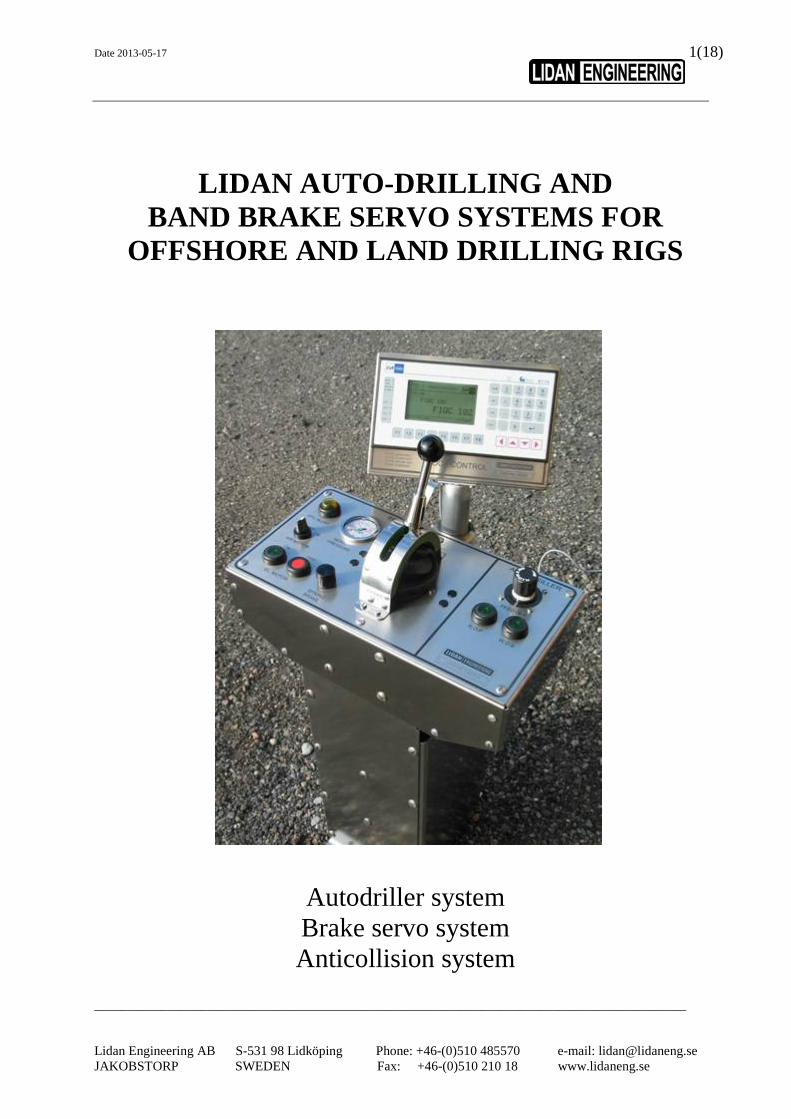
LIDAN AUTO-DRILLING AND BAND BRAKE SERVO SYSTEMS FOR OFFSHORE AND LAND DRILLING RIGS Autodriller system Brake servo system Anticollision system
Date 2013-05-17
_________________________________________________________________________________________ Lidan Engineering AB S-531 98 Lidköping Phone: +46-(0)510 485570 e-mail: [email protected] JAKOBSTORP SWEDEN Fax: +46-(0)510 210 18 www.lidaneng.se
2(18)
The Lidan autodriller and brake servo system includes:
- Remote band brake servo control - Autodriller Feed off & rate of penetration control - Autodriller Weight on bit, Delta P and Torque control - Anti collision system INTRODUCTION
1.0 Introduction Page 3 PRODUCTS
2.1 Lidan DBS servo braking system Page 4 2.2 Lidan ADS autodriller system Page 5 2.3 Lidan BCS anti collision system Page 5
EQUIPMENT DESCRIPTION
3.1 Control console Page 7 3.2 Operator’s Terminal Page 9 3.3 Brake actuator assembly Page 10 3.4 Autodriller transmission assembly Page 11 3.5 Hydraulic power unit Page 12 3.6 Electronic control cabinet Page 13
INSTALLATION AND TESTING
4.1 Installation and testing Page 14
TECHNICAL SPECIFICATION
5.1 Technical specification Page 16 5.2 Dimension drawings Page 17

Date 2013-05-17
_________________________________________________________________________________________ Lidan Engineering AB S-531 98 Lidköping Phone: +46-(0)510 485570 e-mail: [email protected] JAKOBSTORP SWEDEN Fax: +46-(0)510 210 18 www.lidaneng.se
3(18)
1.0 INTRODUCTION
Lidan Engineering.
The company is linked back to 1909, when the Lidan Motor Company designed and manufactured marine winches driven by semi diesel engines. After a time span of about 75 years these winches developed into large hydrostatic driven mooring winch systems for offshore semisubmersible platforms. To-day the responsible company for offshore winches is Lidan Marine AB, while Lidan Engineering AB is responsible for manufacturing and marketing of Automated Drilling and Brake Control systems for offshore and onshore drilling. Since Lidan Engineering installed the first Band Brake Control System on a Transocean semi-submersible drillrig in 1985, the company has included an Autodriller System and an Anti collision System to its product range. Through the years the company continuously has developed and improved these systems and has received DNV (Det Norske Veritas) type approval for the systems for application on drillrigs world wide.
Date 2013-05-17
_________________________________________________________________________________________ Lidan Engineering AB S-531 98 Lidköping Phone: +46-(0)510 485570 e-mail: [email protected] JAKOBSTORP SWEDEN Fax: +46-(0)510 210 18 www.lidaneng.se
4(18)
2.0 PRODUCTS
Over the years, Lidan Engineering has gained a solid reputation for upgrading of drawworks of the band brake type, marketing a unique band brake servo control system. The Lidan hydraulically controlled Autodriller is taking advantage of the well proven brake servo control, with it’s hydraulic band brake actuator, incorporating a servo hydraulic encoder motor for feed back of the drum motion to the brake bands. In fact, when drillrig owners plan for the installation of an Autodriller, the Lidan Autodriller, in combination with the Brake Servo handle control, is the only autodriller on the market, where there is no need to replace the original band brake for an expensive disc brake system. The Autodriller and the Brake handle is operated from one common console, which makes it easy to shift from automated drilling mode to normal pipe handling mode every time a new drillpipe stand shall be added. The console is delivered either as a pedestal or alternatively, integrated with a driller’s main console for remote installation in a driller’s cabin.
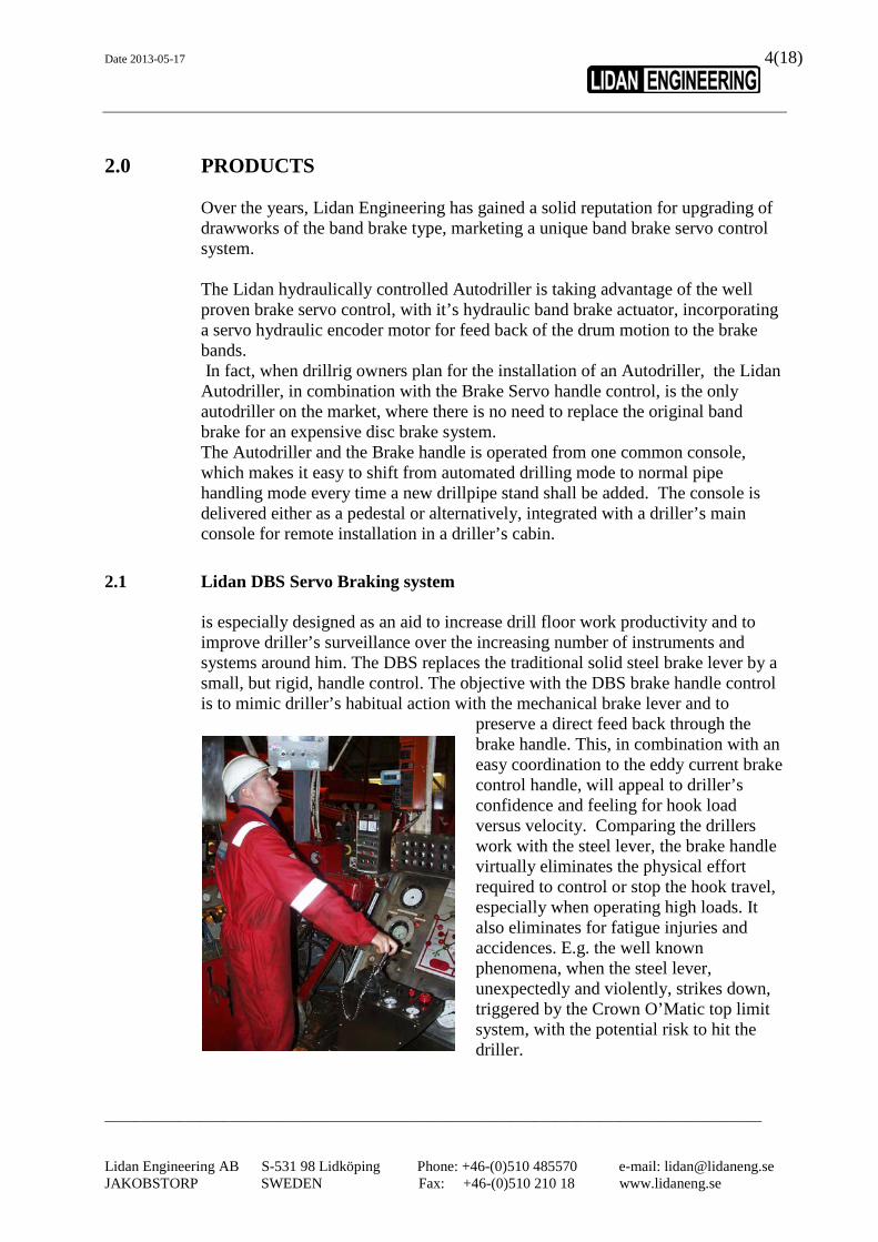
2.1 Lidan DBS Servo Braking system is especially designed as an aid to increase drill floor work productivity and to improve driller’s surveillance over the increasing number of instruments and systems around him. The DBS replaces the traditional solid steel brake lever by a small, but rigid, handle control. The objective with the DBS brake handle control is to mimic driller’s habitual action with the mechanical brake lever and to
preserve a direct feed back through the brake handle. This, in combination with an easy coordination to the eddy current brake control handle, will appeal to driller’s confidence and feeling for hook load versus velocity. Comparing the drillers work with the steel lever, the brake handle virtually eliminates the physical effort required to control or stop the hook travel, especially when operating high loads. It also eliminates for fatigue injuries and accidences. E.g. the well known phenomena, when the steel lever, unexpectedly and violently, strikes down, triggered by the Crown O’Matic top limit system, with the potential risk to hit the driller.

Date 2013-05-17
_________________________________________________________________________________________ Lidan Engineering AB S-531 98 Lidköping Phone: +46-(0)510 485570 e-mail: [email protected] JAKOBSTORP SWEDEN Fax: +46-(0)510 210 18 www.lidaneng.se
5(18)
The DBS Brake Actuator incorporates dual functions, one active and one passive. The active function is directed from drillers brake handle for general block travelling operations, or, when drilling in automated mode, from the ADS Autodriller system. The passive actuator, with its fail safe spring function, is triggered to apply automatically at a situation when, without driller’s notice, an emergency situation is about to occur.
2.2. Lidan ADS Autodriller system is user-friendly and it’s functions easy understandable. The ADS Autodriller system is designed for a high degree of precision in drum line pay out (Feed Off). This will assure maximum Rate of Penetration (ROP) utilization, adjustable between 0-120 m/h (on request up to 300 m/h). With a servo hydraulic encoder motor, linked to the drum shaft via gear transmission and hydraulically connected to the brake actuator, a closed loop feed back system is created, which delivers an absolute steady “Constant Speed” drill line Feed Off. Co-ordinated with the WOB, Delta P and Torque control electronic functions, the system keeps bit weight within very narrow limits, Different operational functions and configurations are available to best suit the individual requirements.

Date 2013-05-17
_________________________________________________________________________________________ Lidan Engineering AB S-531 98 Lidköping Phone: +46-(0)510 485570 e-mail: [email protected] JAKOBSTORP SWEDEN Fax: +46-(0)510 210 18 www.lidaneng.se
6(18)
2.3 Lidan BCS Anti collision System
The Brake Servo system is prepared for simultaneous or later installation of an Anti-collision system. The Lidan BCS Anti collision System is supervised by calculated function of weight, velocity and current block position at down and up travel of the block. In order to keep the travelling block within stored speed limit profiles, a programmable logic controller directs the signals to the auxiliary electric brake for soft braking action. At approaching a preset limit distance to the floor, the crown block, or, if the racking arms or other handling equipment accidentally are being moved into a collision risk area, the Electric Brake gets energized. If required, should not driller take action, the fail safe actuator becomes activated to bring the block into a full stop. The system, in its smallest configuration may be controlled by pushbuttons and if required in more extended systems, all parameters may be supervised by a Drillers Terminal with colour touch screen, positioned on the drillers console. The automatic Anti collision System works in parallel with driller’s manual control of the electric brake and the band brake. Should the driller supersede the block limit profiles, the automatic system will interfere and support braking through the electric brake and the band brake. In autodrilling mode the anti collision system will automatically stop of the Feed Off and apply the brake, when reaching the set position where the current drill pipe length is drilled off. .
Date 2013-05-17
_________________________________________________________________________________________ Lidan Engineering AB S-531 98 Lidköping Phone: +46-(0)510 485570 e-mail: [email protected] JAKOBSTORP SWEDEN Fax: +46-(0)510 210 18 www.lidaneng.se
7(18)
3.0 EQUIPMENT DESCRIPTION
The LIDAN ADS Autodriller with DBS /BCS Brake Control system consists of following main components:
3.1 Operator’s Control Console 3.2 Operator’s Terminal Display 3.3 Brake Actuator Assembly 3.4 Autodriller Transmission Assembly 3.5 Hydraulic Power Unit 3.6 Electronic Control cabinet
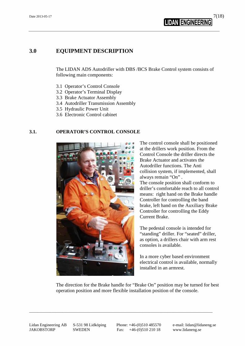
3.1. OPERATOR’S CONTROL CONSOLE
The control console shall be positioned at the drillers work position. From the Control Console the driller directs the Brake Actuator and activates the Autodriller functions. The Anti collision system, if implemented, shall always remain “On” .
The console position shall conform to driller’s comfortable reach to all control means: right hand on the Brake handle Controller for controlling the band brake, left hand on the Auxiliary Brake Controller for controlling the Eddy Current Brake.
The pedestal console is intended for “standing” driller. For “seated” driller, as option, a drillers chair with arm rest consoles is available.
In a more cyber based environment electrical control is available, normally installed in an armrest.
The direction for the Brake handle for “Brake On” position may be turned for best operation position and more flexible installation position of the console.

Date 2013-05-17
_________________________________________________________________________________________ Lidan Engineering AB S-531 98 Lidköping Phone: +46-(0)510 485570 e-mail: [email protected] JAKOBSTORP SWEDEN Fax: +46-(0)510 210 18 www.lidaneng.se
8(18)
As an example the Console’s Panel may include:
1) - electric motor ON - electric motor Off 1 2 3 4 5 - HPU alert/alarm/reset
2) - Pressure indication gauge - Manual emergency stop
3) BRAKE JOYSTICK CONTROL
4) AUTO DRILLER
- “Feed Off” , - “ROP” (rate of penetration) - “WOB”(weight on Bit
5) LIMIT SET with stop positions
- Override - Crown - Autodrill - Floor The Control Console can be equipped with an operator’s terminal with a LCD display or touch screen as integral part of the Anti-collision and/or autodriller system, including digital setting and read out of block position, WOB (t/p), torque, delta P, Feed Off (m/feet / h) and ROP (m/feet / h).
Date 2013-05-17
_________________________________________________________________________________________ Lidan Engineering AB S-531 98 Lidköping Phone: +46-(0)510 485570 e-mail: [email protected] JAKOBSTORP SWEDEN Fax: +46-(0)510 210 18 www.lidaneng.se
9(18)
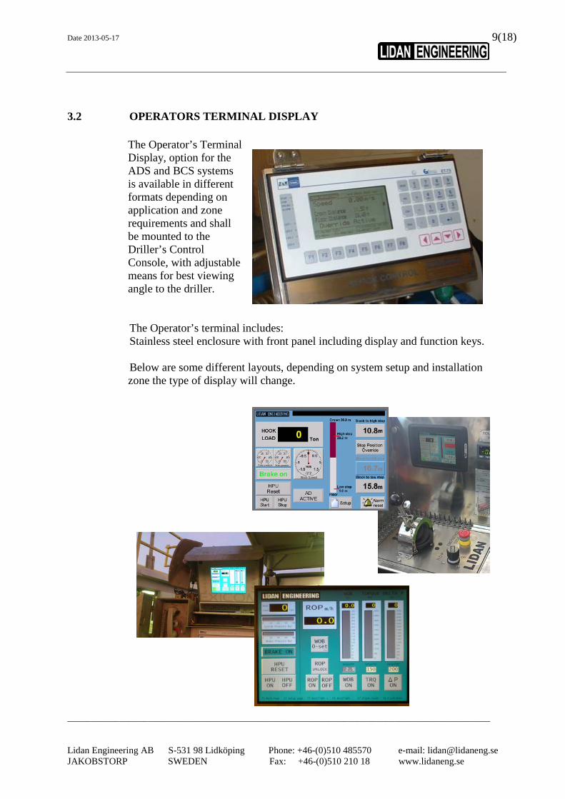
3.2 OPERATORS TERMINAL DISPLAY
The Operator’s Terminal Display, option for the ADS and BCS systems is available in different formats depending on application and zone requirements and shall be mounted to the Driller’s Control Console, with adjustable means for best viewing angle to the driller. The Operator’s terminal includes: Stainless steel enclosure with front panel including display and function keys. Below are some different layouts, depending on system setup and installation zone the type of display will change.

Date 2013-05-17
_________________________________________________________________________________________ Lidan Engineering AB S-531 98 Lidköping Phone: +46-(0)510 485570 e-mail: [email protected] JAKOBSTORP SWEDEN Fax: +46-(0)510 210 18 www.lidaneng.se
10(18)
3.3 BRAKE ACTUATOR ASSEMBLY
The brake actuator is of telescopic design with a dual (Active and Passive) function for minimum space requirements. The actuator shall be positioned in parallel with the drawworks “low clutch” and connected to the drawworks brake shaft. The Passive actuator is fail safe and acts by means of a set of cup springs, charged by hydraulic pressure from the HPU. The Active actuator is manually controlled from the hydraulic brake handle at normal manual controlled operations, while the Passive actuator will apply the band brake automatically in case of an emergency situation triggered by the surveillance system, BCS system, external command or at pressing an emergency button on the Control Console. The surveillance system constantly monitors system pressure to make sure requested force on the brake is maintained. On the actuator a hand pump is mounted, used to open the spring brake in case of power loss or maintenance of the brake system. Active actuator On Passive actuator Off Brake Off Active actuator Off Passive actuator On

Date 2013-05-17
_________________________________________________________________________________________ Lidan Engineering AB S-531 98 Lidköping Phone: +46-(0)510 485570 e-mail: [email protected] JAKOBSTORP SWEDEN Fax: +46-(0)510 210 18 www.lidaneng.se
11(18)
3.4 AUTODRILLER TRANSMISSION ASSEMBLY
The Autodriller Transmission Assembly consists of a compact servo hydraulic feed back motor with bracket assembly, for easy mounting at position at the end of the eddy current brake. The feed back motor is equipped with gear and an air-clutch. A torque arm will be mounted in order for fixation to avoid rotation of the unit. Note: the required rotating torque is negligible
Date 2013-05-17
_________________________________________________________________________________________ Lidan Engineering AB S-531 98 Lidköping Phone: +46-(0)510 485570 e-mail: [email protected] JAKOBSTORP SWEDEN Fax: +46-(0)510 210 18 www.lidaneng.se
12(18)
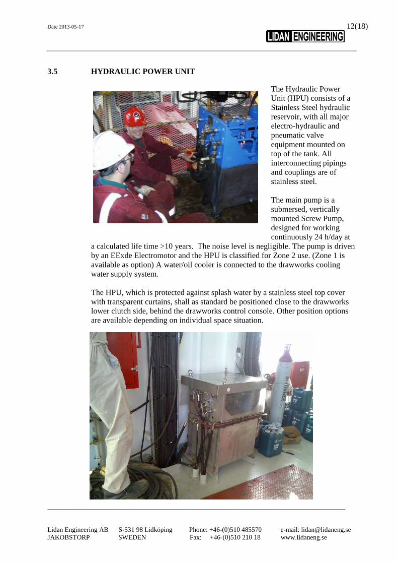
3.5 HYDRAULIC POWER UNIT
The Hydraulic Power Unit (HPU) consists of a Stainless Steel hydraulic reservoir, with all major electro-hydraulic and pneumatic valve equipment mounted on top of the tank. All interconnecting pipings and couplings are of stainless steel.
The main pump is a submersed, vertically mounted Screw Pump, designed for working continuously 24 h/day at
a calculated life time >10 years. The noise level is negligible. The pump is driven by an EExde Electromotor and the HPU is classified for Zone 2 use. (Zone 1 is available as option) A water/oil cooler is connected to the drawworks cooling water supply system. The HPU, which is protected against splash water by a stainless steel top cover with transparent curtains, shall as standard be positioned close to the drawworks lower clutch side, behind the drawworks control console. Other position options are available depending on individual space situation.

Date 2013-05-17
_________________________________________________________________________________________ Lidan Engineering AB S-531 98 Lidköping Phone: +46-(0)510 485570 e-mail: [email protected] JAKOBSTORP SWEDEN Fax: +46-(0)510 210 18 www.lidaneng.se
13(18)
3.6 ELECTRONIC CONTROL CABINET.
The Electronic Control cabinet shall be installed in safe area. (Zone 2 purge system as an option) The Control cabinet includes a programmable logic controller (Siemens), motor starter relay, ex-barriers and interface relays. The PLC is programmed keep control of the hydraulic system functions and depending on configuration include BCS and ADS functionality. If a system without a driller operated display/screen is installed, a small display will be installed in the cabinet door. The display is used to monitor the status, handle HPU alarms and setup of the system.
Date 2013-05-17
_________________________________________________________________________________________ Lidan Engineering AB S-531 98 Lidköping Phone: +46-(0)510 485570 e-mail: [email protected] JAKOBSTORP SWEDEN Fax: +46-(0)510 210 18 www.lidaneng.se
14(18)
4.1 INSTALLATION & TESTING
Upon agreement Lidan service personnel or approved Lidan representatives may provide installation of the equipment. Installation may be performed either during on-going drilling activities, where final hook on is done at a time window availability of maximum 6 hours, or during the time period for demobilisation / mobilisation, what ever suits the rig activity schedule. Upon request Lidan can propose installation and quote installation material:
Installation : Mechanical installation comprises: Hydraulic Power Unit Brake Actuator Feed off Servo motor Control Console
Piping / hoses interconnection: Hydraulic Power Unit
Brake Actuator Feed off Servo motor Control Console Electrical installation: Interconnection of components. Power supply Interfacing signals Interface & interconnections: drawworks Low / High Clutch (air) drawworks Relay Valve (air) drawworks Release Valve (air) drawworks Toggle Valve (air) elmagco brake engage. (electric) SCR throttle (electric) ADS process parameters (electric) Installation material: Lidan supply (optional):
Installation material ( hoses, couplings etc) as well as installation tools may be
quoted upon separate agreement to accompany the delivery of the system
equipment. Surplus installation material and Lidan installation tools shall
be sent back by Buyer to Lidan or Lidan representative at Buyers cost, immediately after completed and approved installation.

Date 2013-05-17
_________________________________________________________________________________________ Lidan Engineering AB S-531 98 Lidköping Phone: +46-(0)510 485570 e-mail: [email protected] JAKOBSTORP SWEDEN Fax: +46-(0)510 210 18 www.lidaneng.se
15(18)
Assistance: Assistance performed by rig personnel,
free of charge for the Seller Typical assistance required:
filling of hydraulic oil into HPU
water connection to oil cooler HPU Welding: fixation of base plate, fixation of control console welding of protection covers Electric work: Cabling Junction box connection Buyers supply: Wiring to Lidan marshalling
junction boxes. One Barrel (200 l) Hydraulic Oil ” Shell Tellus Oil S 46” or equivalent.
Time for installation: Time for installation is by experience 3-5 days at site, however, this time can become extended due to unexpected work impediments, etc.
Testing: Before delivery, all equipment delivered
by Lidan is subject to a thorough FAT-test procedure. The approved FAT-test document is a part of the delivery.
After approved installation on the rig, testing of the equipment and training of drill crew will be performed to the rig personnel under supervision of Lidan personnel or representative personnel approved by Lidan.
Date 2013-05-17
_________________________________________________________________________________________ Lidan Engineering AB S-531 98 Lidköping Phone: +46-(0)510 485570 e-mail: [email protected] JAKOBSTORP SWEDEN Fax: +46-(0)510 210 18 www.lidaneng.se
16(18)
5 TECHNICAL SPECIFICATION 5.1 Technical specification
Hydraulic Power Unit : Power supply : ........................... 4,6 kW Voltage and frequency specified at order. (400-500 VAC 50/60 Hz) Oil tank volume: ......................... 150 l Oil quality: ................................ Shell Tellus Oil S 46 or equivalent Normal working pressure: ......... 34 Bar Cooling water supply: ............... ½” BSP, to be connected to fresh water supply for drawworks brake. Cooling water consumption: ..... 15 LPM Air supply: ................................. 6-10 Bar, Connection ½” BSP. Air quality: ................................ ISO 8573-1 Class 6.4.3 or better. Air Consumption (autodriler): ... Normal working mode max 50 NL/Min . Dimensions (lxbxh): 600 x 700 x 1125 mm Weight: ....................................... 170 Kg Installation: ................................. min 150 mm from wall. Front and right or left side accessible for maintenance. Location: .................................... Adjacent to the drawworks Zone 2. Contact Lidan for advice and layout. Brake actuator: Dimensions (lxbxh) .................... 1245 x 300 x 280 mm Weight: ....................................... 125 Kg Control console: Dimensions (lxbxh) .................... 478 x 283 x 992 mm Weight: ....................................... 40 Kg Location alternatives: ................. - On open drillfloor or in a drillers cabin, positioned at any distance from the drawworks, for standing or seated driller. Design alternatives: .................... - Control panel to be inserted in drillers main console. - Control Console on pedestal - A left and right hand consoles mounted on a gliding/rotated chair, with added control means for auxiliary brake, clutch control, etc. Autodriller encoder motor: Dimensions (lxbxh) .................... 400 x 380 x 250 mm Weight: ....................................... 30 Kg Location: .................................... Baylor brake shaft outlet Electronic control cabinet : Power supply: ............................ 400-500 VAC 50/60 Hz Dimensions (lxbxh) .................... 600 x 600 x 200 mm Weight: ....................................... 30 Kg Location: .................................... Safe area , (Zone 2 as option) Interface (depending on config): Hook load by hydraulic sensor or 4-20 mA signal.
Torque and Delta P by 4-20 mA signal Auxiliary brake, SCR and clutch control by potential free contacts.
Terminal display depending on configuration and installation zone: Dimensions (lxbxh) .................... 300 x 200 x 100 Weight: ....................................... 5 Kg Power supply: ............................. Through electronic control cabinet

Date 2013-05-17
_________________________________________________________________________________________ Lidan Engineering AB S-531 98 Lidköping Phone: +46-(0)510 485570 e-mail: [email protected] JAKOBSTORP SWEDEN Fax: +46-(0)510 210 18 www.lidaneng.se
17(18)
5.2 Dimension drawings Control console (Drawing no 20707)
Brake actuator assembly (Installation drawing no 20884)
SERVO PRESSURE FEED OFF
R.O.P W.O.B
EL. MOTOR
ON OFF
SPRINGBRAKE
AIR MOTOROFF
ON
EL.
MO
TOR
ON
OFF
SP
RIN
GB
RA
KE
ON
OFF
AIR
MO
TOR
SE
RV
O P
RE
SS
UR
EFE
ED
OFF
R.O
.PW
.O.B

Date 2013-05-17
_________________________________________________________________________________________ Lidan Engineering AB S-531 98 Lidköping Phone: +46-(0)510 485570 e-mail: [email protected] JAKOBSTORP SWEDEN Fax: +46-(0)510 210 18 www.lidaneng.se
18(18)
Hydraulic power unit (Drawing no 10931)