dragon servo drive - esi · pdf filethe dragon servo drive provides two 24 v brake drivers,...
TRANSCRIPT
1 ESI Motion Document 100235-00F 4/17/2015
DR
AG
ON
SE
RV
O D
RIV
E
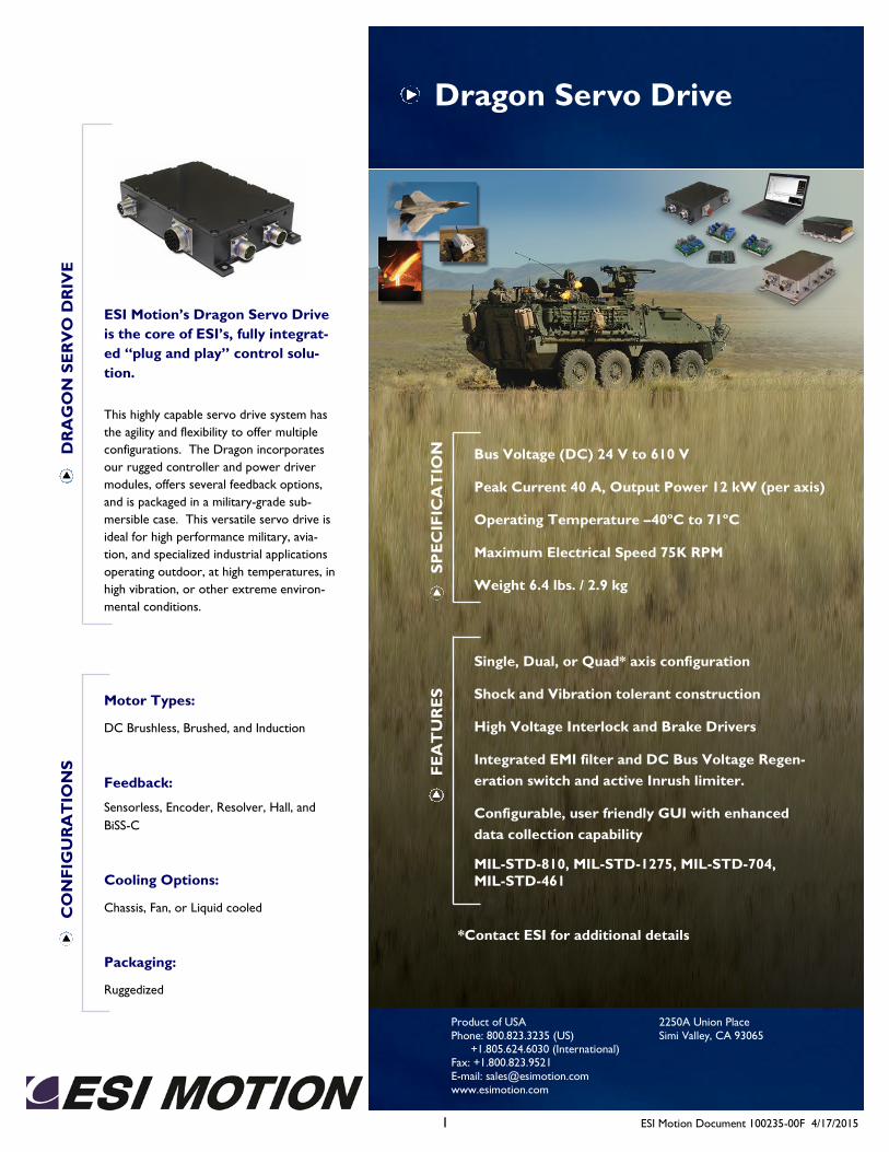
ESI Motion’s Dragon Servo Drive
is the core of ESI’s, fully integrat-
ed “plug and play” control solu-
tion.
This highly capable servo drive system has
the agility and flexibility to offer multiple
configurations. The Dragon incorporates
our rugged controller and power driver
modules, offers several feedback options,
and is packaged in a military-grade sub-
mersible case. This versatile servo drive is
ideal for high performance military, avia-
tion, and specialized industrial applications
operating outdoor, at high temperatures, in
high vibration, or other extreme environ-
mental conditions.
Motor Types:
DC Brushless, Brushed, and Induction
Feedback:
Sensorless, Encoder, Resolver, Hall, and
BiSS-C
Cooling Options:
Chassis, Fan, or Liquid cooled
Packaging:
Ruggedized
Dragon Servo Drive C
ON
FIG
UR
AT
ION
S
Single, Dual, or Quad* axis configuration
Shock and Vibration tolerant construction
High Voltage Interlock and Brake Drivers
Integrated EMI filter and DC Bus Voltage Regen-
eration switch and active Inrush limiter.
Configurable, user friendly GUI with enhanced
data collection capability
MIL-STD-810, MIL-STD-1275, MIL-STD-704,
MIL-STD-461
FE
AT
UR
ES
Bus Voltage (DC) 24 V to 610 V
Peak Current 40 A, Output Power 12 kW (per axis)
Operating Temperature –40ºC to 71ºC
Maximum Electrical Speed 75K RPM
Weight 6.4 lbs. / 2.9 kg
SP
EC
IFIC
AT
ION
*Contact ESI for additional details
2250A Union Place
Simi Valley, CA 93065
Product of USA
Phone: 800.823.3235 (US) +1.805.624.6030 (International) Fax: +1.800.823.9521
E-mail: [email protected]
www.esimotion.com
2 ESI Motion Document 100235-00F 4/17/2015
Dragon Servo Drive D
RA
GO
N S
ER
VO
DR
IVE
Overview
The Dragon Servo Drive incorporates our rugged controller and servo drive modules into a military grade package.
The following describes both the electrical and physical interfaces for the Dragon Servo Drive. Included in this docu-
ment is information necessary to integrate the Dragon Servo Drive with other system components.
In order to design a multi-use capability, networking has been emphasized in the Dragon Servo Drive. The Dragon
Servo Drive can be connected to the following two types of networks:
RS-422, Controller Area Network (CAN)
Both networks are ideal for real-time embedded networking. They have been proven to be stable and robust as well as
flexible. Thus, the Dragon Servo Drive can easily be modified through software to accept commands and report feed-
back without hardware modification.
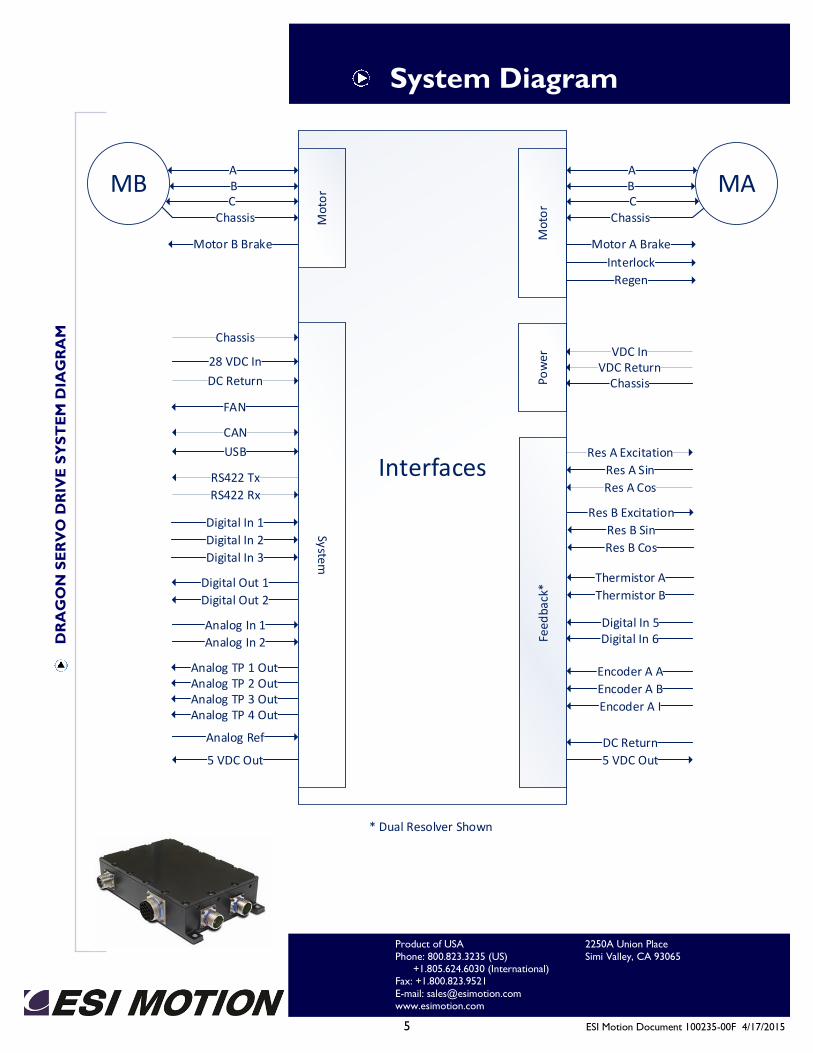
This document discusses the system interconnect by functional group. The four groups are as follows:
Power, Motor, System, Feedback
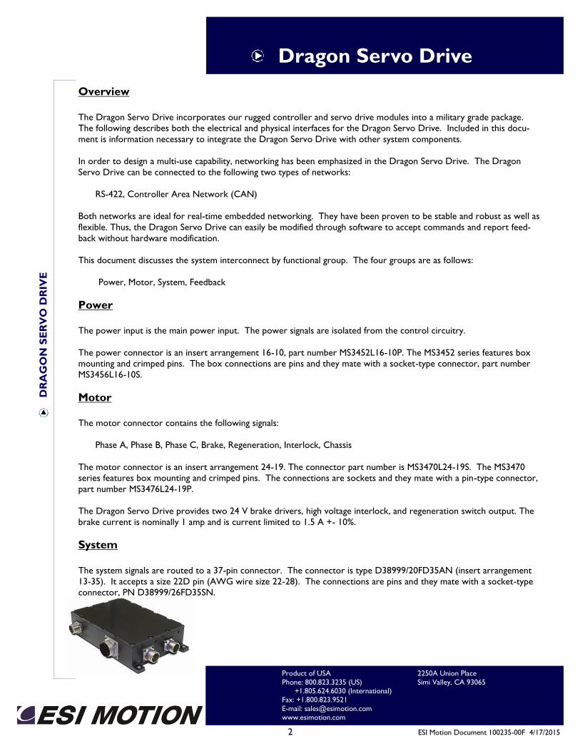
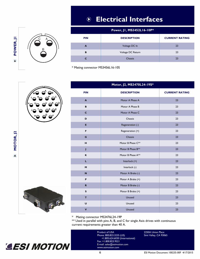
Power
The power input is the main power input. The power signals are isolated from the control circuitry.
The power connector is an insert arrangement 16-10, part number MS3452L16-10P. The MS3452 series features box
mounting and crimped pins. The box connections are pins and they mate with a socket-type connector, part number
MS3456L16-10S.
Motor The motor connector contains the following signals:
Phase A, Phase B, Phase C, Brake, Regeneration, Interlock, Chassis
The motor connector is an insert arrangement 24-19. The connector part number is MS3470L24-19S. The MS3470
series features box mounting and crimped pins. The connections are sockets and they mate with a pin-type connector,
part number MS3476L24-19P.
The Dragon Servo Drive provides two 24 V brake drivers, high voltage interlock, and regeneration switch output. The
brake current is nominally 1 amp and is current limited to 1.5 A +- 10%.
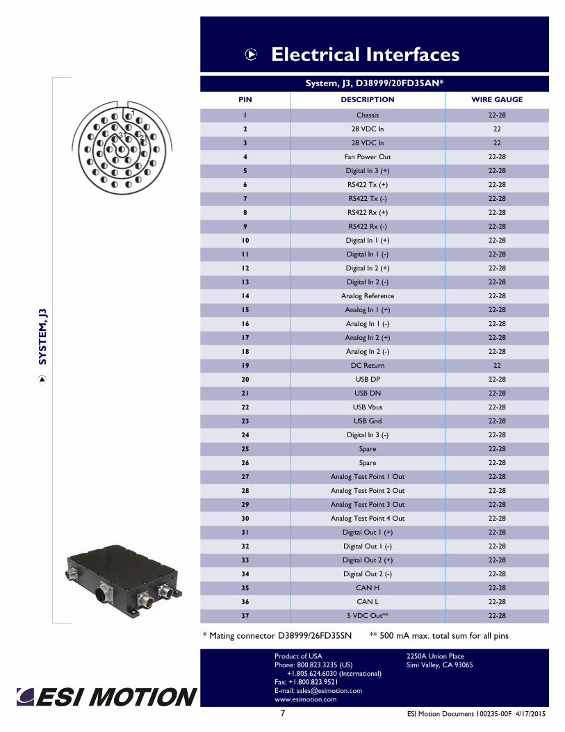
System
The system signals are routed to a 37-pin connector. The connector is type D38999/20FD35AN (insert arrangement
13-35). It accepts a size 22D pin (AWG wire size 22-28). The connections are pins and they mate with a socket-type
connector, PN D38999/26FD35SN.
2250A Union Place
Simi Valley, CA 93065
Product of USA
Phone: 800.823.3235 (US) +1.805.624.6030 (International) Fax: +1.800.823.9521
E-mail: [email protected] www.esimotion.com
3 ESI Motion Document 100235-00F 4/17/2015
Dragon Servo Drive D
RA
GO
N S
ER
VO
DR
IVE
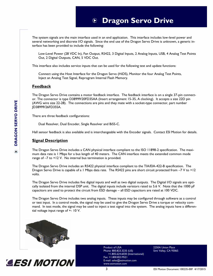
The system signals are the main interface used in an end application. This interface includes low-level power and
several networking and discrete I/O signals. Since the end use of the Dragon Servo Drive is unknown, a generic in-
terface has been provided to include the following:
Low-Level Power (28 VDC In), Fan Output, RS422, 3 Digital Inputs, 2 Analog Inputs, USB, 4 Analog Test Points
Out, 2 Digital Outputs, CAN, 5 VDC Out.
This interface also includes service inputs that can be used for the following test and update functions:
Connect using the Host Interface for the Dragon Servo (HiDS), Monitor the four Analog Test Points,
Inject an Analog Test Signal, Reprogram Internal Flash Memory.
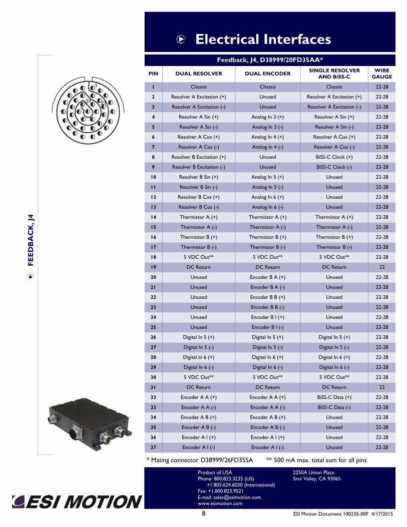
Feedback
The Dragon Servo Drive contains a motor feedback interface. The feedback interface is on a single 37-pin connect-
or. The connector is type D38999/20FD35AA (Insert arrangement 15-35, A clocking). It accepts a size 22D pin
(AWG wire size 22-28). The connections are pins and they mate with a socket-type connector, part number
JD38999/26FD35SA.
There are three feedback configurations:
Dual Resolver, Dual Encoder, Single Resolver and BiSS-C.
Hall sensor feedback is also available and is interchangeable with the Encoder signals. Contact ESI Motion for details.
Signal Description
The Dragon Servo Drive includes a CAN physical interface compliant to the ISO 11898-2 specification. The maxi-
mum data rate is 1 Mbps for a bus length of 40 meters. The CAN interface meets the extended common mode
range of –7 to +12 V. No internal bus termination is provided.
The Dragon Servo Drive includes an RS422 physical interface compliant to the TIA/EIA-422-B specification. The
Dragon Servo Drive is capable of a 1 Mbps data rate. The RS422 pins are short circuit protected from –7 V to +12
volts.
The Dragon Servo Drive includes five digital inputs and well as two digital outputs. The Digital I/O signals are opti-
cally isolated from the internal DSP unit. The digital inputs include varistors rated to 5.6 V. Note that the 1000 pF
capacitors are used to protect the circuit from ESD damage – all ESD capacitors are rated at 100 VDC.
The Dragon Servo Drive includes two analog inputs. These inputs may be configured through software as a control
or test input. In a control mode, the signal may be used to give the Dragon Servo Drive a torque or velocity com-
mand. In test mode, the signal may be used to inject a test signal into the system. The analog inputs have a differen-
tial voltage input range of +- 10 V.
2250A Union Place
Simi Valley, CA 93065
Product of USA
Phone: 800.823.3235 (US) +1.805.624.6030 (International) Fax: +1.800.823.9521
E-mail: [email protected] www.esimotion.com
4 ESI Motion Document 100235-00F 4/17/2015
Dragon Servo Drive D
RA
GO
N S
ER
VO
DR
IVE
The four analog test points are routed to the system connector for monitoring. The user may use the HiDS to setup
the analog test points. The voltage range on the analog test points are +- 2.5 V. The test points are buffered with a
100 Ohm resistor.
The user may connect a standard USB port to the USB D+, USB D-, USB VBUS and USB GND for access to the
HiDS functions.
The user may use the USB port to reprogram the internal FLASH memory. A flash update program is provided by
ESI Motion.
2250A Union Place
Simi Valley, CA 93065
Product of USA
Phone: 800.823.3235 (US) +1.805.624.6030 (International) Fax: +1.800.823.9521
E-mail: [email protected] www.esimotion.com
5 ESI Motion Document 100235-00F 4/17/2015
System Diagram D
RA
GO
N S
ER
VO
DR
IVE
SY
ST
EM
DIA
GR
AM
2250A Union Place
Simi Valley, CA 93065
Product of USA
Phone: 800.823.3235 (US) +1.805.624.6030 (International) Fax: +1.800.823.9521
E-mail: [email protected] www.esimotion.com
DC Return
CAN
RS422 Tx
Chassis
RS422 RxRes A Cos
Res A Excitation
VDC ReturnVDC In
Interfaces
Pow
erFe
edba
ck*
System
Res A Sin
Digital Out 2
Digital Out 1
28 VDC In
Chassis
Digital In 1
Digital In 2
Analog In 1
Analog In 2
Analog TP 1 OutAnalog TP 2 OutAnalog TP 3 OutAnalog TP 4 Out
Thermistor A
Analog Ref
USB
Digital In 5Digital In 6
Thermistor B
Digital In 3
FAN
5 VDC Out
Res B Cos
Res B Excitation
Res B Sin
* Dual Resolver Shown
5 VDC Out
DC Return
Encoder A A
Encoder A B
Encoder A I
MAChassis
Mot
or
MBChassis M
oto
r
6 ESI Motion Document 100235-00F 4/17/2015
Electrical Interfaces P
OW
ER
, J1
Power, J1, MS3452L16-10P*
PIN DESCRIPTION CURRENT RATING
A Voltage DC In 23
B Voltage DC Return 23
C Chassis 23
MO
TO
R, J2
Motor, J2, MS3470L24-19S*
PIN DESCRIPTION CURRENT RATING
A Motor A Phase A 23
B Motor A Phase B 23
C Motor A Phase C 23
D Chassis 23
E Regeneration (-) 23
F Regeneration (+) 23
G Chassis 23
H Motor B Phase C** 23
J Motor B Phase B** 23
K Motor B Phase A** 23
L Interlock (+) 23
M Interlock (-) 23
N Motor A Brake (-) 23
P Motor A Brake (+) 23
R Motor B Brake (-) 23
S Motor B Brake (+) 23
T Unused 23
U Unused 23
V Unused 23
* Mating connector MS3476L24-19P
** Used in parallel with pins A, B, and C for single Axis drives with continuous
current requirements greater than 40 A.
* Mating connector MS3456L16-10S
2250A Union Place
Simi Valley, CA 93065
Product of USA
Phone: 800.823.3235 (US) +1.805.624.6030 (International) Fax: +1.800.823.9521
E-mail: [email protected] www.esimotion.com
7 ESI Motion Document 100235-00F 4/17/2015
Electrical Interfaces S
YS
TE
M, J3
System, J3, D38999/20FD35AN*
PIN DESCRIPTION WIRE GAUGE
1 Chassis 22-28
2 28 VDC In 22
3 28 VDC In 22
4 Fan Power Out 22-28
5 Digital In 3 (+) 22-28
6 RS422 Tx (+) 22-28
7 RS422 Tx (-) 22-28
8 RS422 Rx (+) 22-28
9 RS422 Rx (-) 22-28
10 Digital In 1 (+) 22-28
11 Digital In 1 (-) 22-28
12 Digital In 2 (+) 22-28
13 Digital In 2 (-) 22-28
14 Analog Reference 22-28
15 Analog In 1 (+) 22-28
16 Analog In 1 (-) 22-28
17 Analog In 2 (+) 22-28
18 Analog In 2 (-) 22-28
19 DC Return 22
20 USB DP 22-28
21 USB DN 22-28
22 USB Vbus 22-28
23 USB Gnd 22-28
24 Digital In 3 (-) 22-28
25 Spare 22-28
26 Spare 22-28
27 Analog Test Point 1 Out 22-28
28 Analog Test Point 2 Out 22-28
29 Analog Test Point 3 Out 22-28
30 Analog Test Point 4 Out 22-28
31 Digital Out 1 (+) 22-28
32 Digital Out 1 (-) 22-28
33 Digital Out 2 (+) 22-28
34 Digital Out 2 (-) 22-28
35 CAN H 22-28
36 CAN L 22-28
37 5 VDC Out** 22-28
* Mating connector D38999/26FD35SN ** 500 mA max. total sum for all pins
2250A Union Place
Simi Valley, CA 93065
Product of USA
Phone: 800.823.3235 (US) +1.805.624.6030 (International) Fax: +1.800.823.9521
E-mail: [email protected] www.esimotion.com
8 ESI Motion Document 100235-00F 4/17/2015
Electrical Interfaces F
EE
DB
AC
K, J4
Feedback, J4, D38999/20FD35AA*
PIN DUAL RESOLVER WIRE
GAUGE DUAL ENCODER
SINGLE RESOLVER
AND BiSS-C
1 Chassis 22-28 Chassis Chassis
2 Resolver A Excitation (+) 22-28 Unused Resolver A Excitation (+)
3 Resolver A Excitation (-) 22-28 Unused Resolver A Excitation (-)
4 Resolver A Sin (+) 22-28 Analog In 3 (+) Resolver A Sin (+)
5 Resolver A Sin (-) 22-28 Analog In 3 (-) Resolver A Sin (-)
6 Resolver A Cos (+) 22-28 Analog In 4 (+) Resolver A Cos (+)
7 Resolver A Cos (-) 22-28 Analog In 4 (-) Resolver A Cos (-)
8 Resolver B Excitation (+) 22-28 Unused BiSS-C Clock (+)
9 Resolver B Excitation (-) 22-28 Unused BiSS-C Clock (-)
10 Resolver B Sin (+) 22-28 Analog In 5 (+) Unused
11 Resolver B Sin (-) 22-28 Analog In 5 (-) Unused
12 Resolver B Cos (+) 22-28 Analog In 6 (+) Unused
13 Resolver B Cos (-) 22-28 Analog In 6 (-) Unused
14 Thermistor A (+) 22-28 Thermistor A (+) Thermistor A (+)
15 Thermistor A (-) 22-28 Thermistor A (-) Thermistor A (-)
16 Thermistor B (+) 22-28 Thermistor B (+) Thermistor B (+)
17 Thermistor B (-) 22-28 Thermistor B (-) Thermistor B (-)
18 5 VDC Out** 22-28 5 VDC Out** 5 VDC Out**
19 DC Return 22 DC Return DC Return
20 Unused 22-28 Encoder B A (+) Unused
21 Unused 22-28 Encoder B A (-) Unused
22 Unused 22-28 Encoder B B (+) Unused
23 Unused 22-28 Encoder B B (-) Unused
24 Unused 22-28 Encoder B I (+) Unused
25 Unused 22-28 Encoder B I (-) Unused
26 Digital In 5 (+) 22-28 Digital In 5 (+) Digital In 5 (+)
27 Digital In 5 (-) 22-28 Digital In 5 (-) Digital In 5 (-)
28 Digital In 6 (+) 22-28 Digital In 6 (+) Digital In 6 (+)
29 Digital In 6 (-) 22-28 Digital In 6 (-) Digital In 6 (-)
30 5 VDC Out** 22-28 5 VDC Out** 5 VDC Out**
31 DC Return 22 DC Return DC Return
32 Encoder A A (+) 22-28 Encoder A A (+) BiSS-C Data (+)
33 Encoder A A (-) 22-28 Encoder A A (-) BiSS-C Data (-)
34 Encoder A B (+) 22-28 Encoder A B (+) Unused
35 Encoder A B (-) 22-28 Encoder A B (-) Unused
36 Encoder A I (+) 22-28 Encoder A I (+) Unused
37 Encoder A I (-) 22-28 Encoder A I (-) Unused
* Mating connector D38999/26FD35SA ** 500 mA max. total sum for all pins
2250A Union Place
Simi Valley, CA 93065
Product of USA
Phone: 800.823.3235 (US) +1.805.624.6030 (International) Fax: +1.800.823.9521
E-mail: [email protected] www.esimotion.com
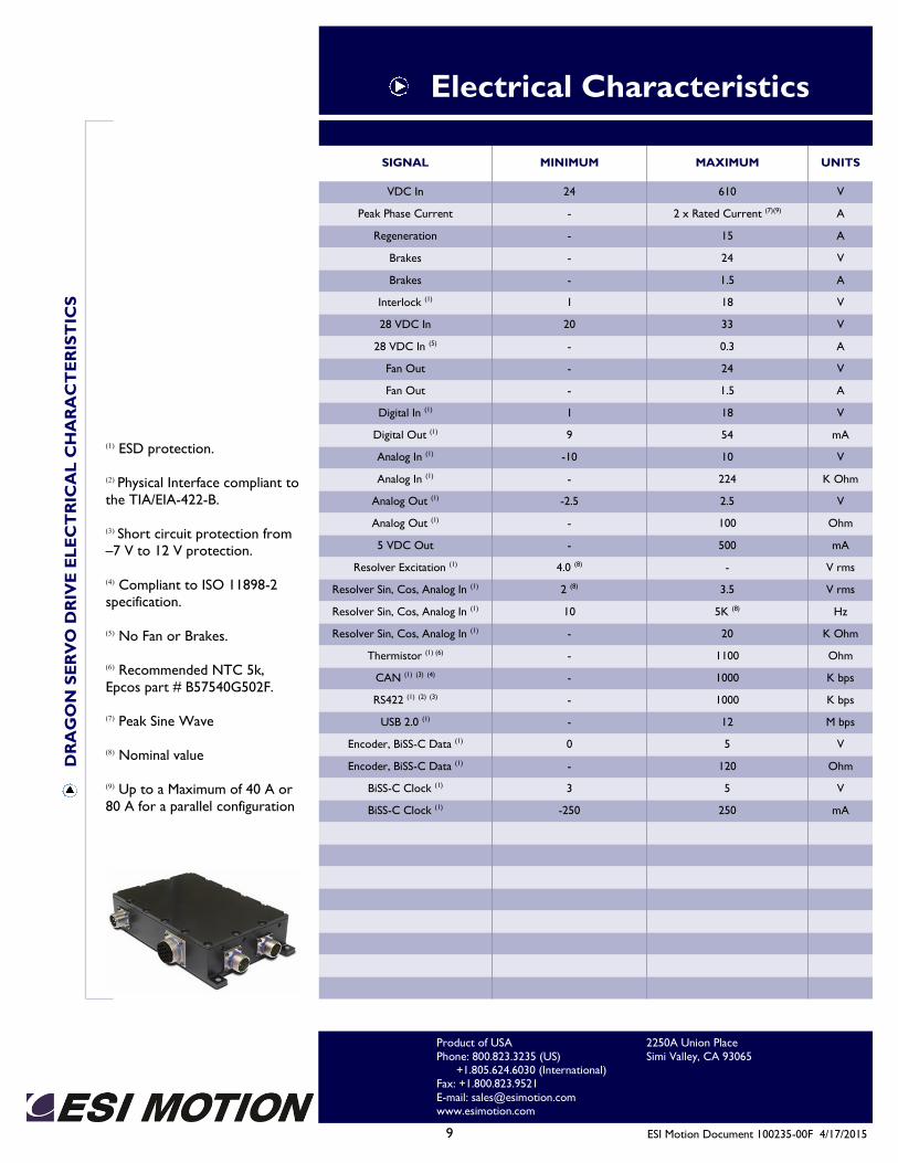
9 ESI Motion Document 100235-00F 4/17/2015
Electrical Characteristics D
RA
GO
N S
ER
VO
DR
IVE
EL
EC
TR
ICA
L C
HA
RA
CT
ER
IST
ICS
SIGNAL MINIMUM MAXIMUM UNITS
VDC In 24 610 V
Peak Phase Current - 2 x Rated Current (7)(9) A
Regeneration - 15 A
Brakes - 24 V
Brakes - 1.5 A
Interlock (1) 1 18 V
28 VDC In 20 33 V
28 VDC In (5) - 0.3 A
Fan Out - 24 V
Fan Out - 1.5 A
Digital In (1) 1 18 V
Digital Out (1) 9 54 mA
Analog In (1) -10 10 V
Analog In (1) - 224 K Ohm
Analog Out (1) -2.5 2.5 V
Analog Out (1) - 100 Ohm
5 VDC Out - 500 mA
Resolver Excitation (1) 4.0 (8) - V rms
Resolver Sin, Cos, Analog In (1) 2 (8) 3.5 V rms
Resolver Sin, Cos, Analog In (1) 10 5K (8) Hz
Resolver Sin, Cos, Analog In (1) - 20 K Ohm
Thermistor (1) (6) - 1100 Ohm
CAN (1) (3) (4) - 1000 K bps
RS422 (1) (2) (3) - 1000 K bps
USB 2.0 (1) - 12 M bps
Encoder, BiSS-C Data (1) 0 5 V
Encoder, BiSS-C Data (1) - 120 Ohm
BiSS-C Clock (1) 3 5 V
BiSS-C Clock (1) -250 250 mA
(1) ESD protection.
(2) Physical Interface compliant to
the TIA/EIA-422-B.
(3) Short circuit protection from
–7 V to 12 V protection.
(4) Compliant to ISO 11898-2
specification.
(5) No Fan or Brakes.
(6) Recommended NTC 5k,
Epcos part # B57540G502F.
(7) Peak Sine Wave
(8) Nominal value
(9) Up to a Maximum of 40 A or
80 A for a parallel configuration
2250A Union Place
Simi Valley, CA 93065
Product of USA
Phone: 800.823.3235 (US) +1.805.624.6030 (International) Fax: +1.800.823.9521
E-mail: [email protected] www.esimotion.com
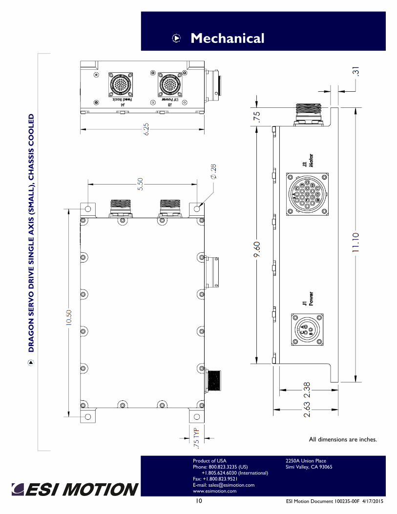
10 ESI Motion Document 100235-00F 4/17/2015
Mechanical D
RA
GO
N S
ER
VO
DR
IVE
SIN
GL
E A
XIS
(S
MA
LL
), C
HA
SS
IS C
OO
LE
D
All dimensions are inches.
2250A Union Place
Simi Valley, CA 93065
Product of USA
Phone: 800.823.3235 (US) +1.805.624.6030 (International) Fax: +1.800.823.9521
E-mail: [email protected] www.esimotion.com
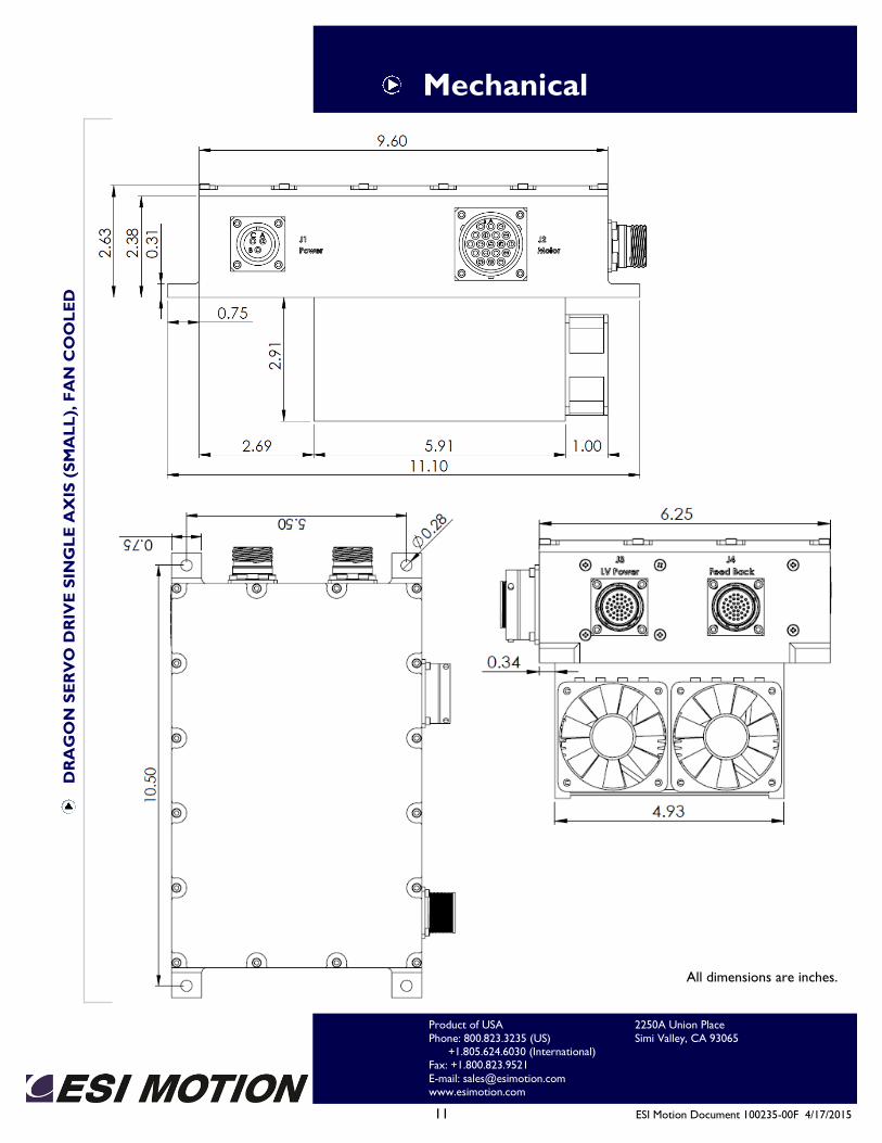
11 ESI Motion Document 100235-00F 4/17/2015
Mechanical D
RA
GO
N S
ER
VO
DR
IVE
SIN
GL
E A
XIS
(S
MA
LL
), F
AN
CO
OL
ED
All dimensions are inches.
2250A Union Place
Simi Valley, CA 93065
Product of USA
Phone: 800.823.3235 (US) +1.805.624.6030 (International) Fax: +1.800.823.9521
E-mail: [email protected] www.esimotion.com
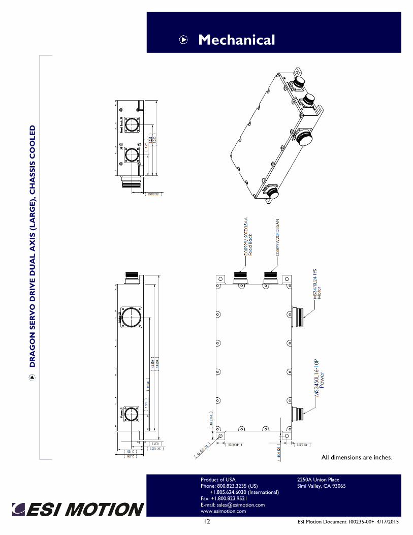
12 ESI Motion Document 100235-00F 4/17/2015
Mechanical D
RA
GO
N S
ER
VO
DR
IVE
DU
AL
AX
IS (
LA
RG
E),
CH
AS
SIS
CO
OL
ED
All dimensions are inches.
2250A Union Place
Simi Valley, CA 93065
Product of USA
Phone: 800.823.3235 (US) +1.805.624.6030 (International) Fax: +1.800.823.9521
E-mail: [email protected] www.esimotion.com
13 ESI Motion Document 100235-00F 4/17/2015
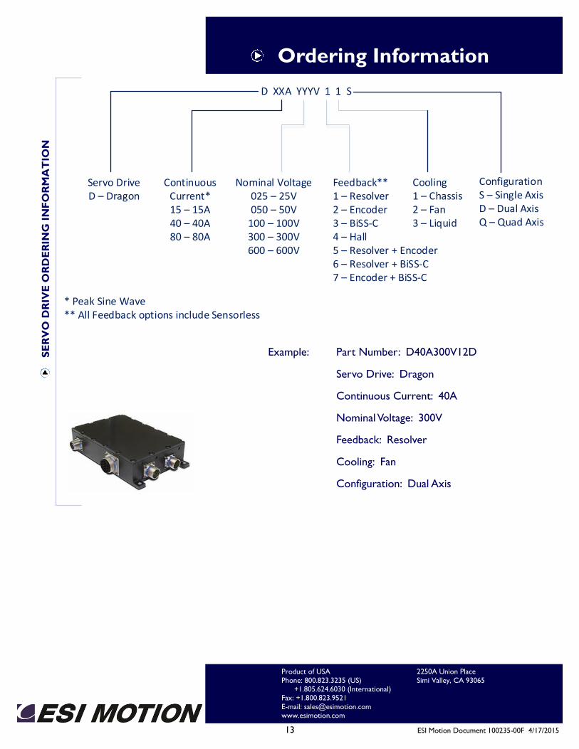
Ordering Information
Example: Part Number: D40A300V12D
Servo Drive: Dragon
Continuous Current: 40A
Nominal Voltage: 300V
Feedback: Resolver
Cooling: Fan
Configuration: Dual Axis
SE
RV
O D
RIV
E O
RD
ER
ING
IN
FO
RM
AT
ION
2250A Union Place
Simi Valley, CA 93065
Product of USA
Phone: 800.823.3235 (US) +1.805.624.6030 (International) Fax: +1.800.823.9521
E-mail: [email protected] www.esimotion.com
D XXA YYYV 1 1 S
Servo DriveD – Dragon
Continuous Current*15 – 15A40 – 40A80 – 80A
Nominal Voltage025 – 25V050 – 50V
100 – 100V300 – 300V600 – 600V
Cooling1 – Chassis2 – Fan3 – Liquid
* Peak Sine Wave** All Feedback options include Sensorless
Feedback**1 – Resolver2 – Encoder3 – BiSS-C4 – Hall5 – Resolver + Encoder6 – Resolver + BiSS-C7 – Encoder + BiSS-C
ConfigurationS – Single AxisD – Dual AxisQ – Quad Axis