library.e.abb.com · 2015-05-11library.e.abb.com
TRANSCRIPT

Relays
Low Voltage Products & Systems 6.AABB Inc. • 888-385-1221 • www.abb.us/lowvoltage 1SXU000023C0202 Rev. A
6
Control, timing & monitoring relaysIndex
Continued next page
6 - Control, timing & monitoring relays
Control relays ...............................................................6.1 - 6.38Features and benefits .................................................................................................................6.1
General information Panorama ....................................................................................................................6.2 - 6.3 Technical terms and definitions.............................................................................................6.4 IEC Standards, utilization categories ....................................................................................6.5 Pilot duty ratings and overload trip classes ...........................................................................6.6 NF/NFZ control relays ..........................................................................................................6.7
Selection NF, 4 & 8 pole ......................................................................................................................6.8 NFZ, 4 & 8 pole ....................................................................................................................6.9 NS/NSL 4 & 8 pole ............................................................................................................6.10 NS/NSL 4 & 8 pole, spring terminated ...............................................................................6.11 K6 miniature, 4 pole ...........................................................................................................6.12 KC6 miniature, 4 pole ........................................................................................................6.13 KC6 interface relays, 4 pole ...............................................................................................6.14
Accessory fitting details NF(Z), 4 & 8 pole ................................................................................................................6.15 NS/L 4 & 8 pole, screw terminated.....................................................................................6.16 NS/L 4 & 8 pole, spring terminated ....................................................................................6.17
Accessories Auxiliary contact blocks & interlocks ...................................................................................6.18 Surge suppression for control relay coils ............................................................................6.19 Electronic timers ................................................................................................................6.20 Function markers, protective covers & coil terminal blocks .................................................6.21
Terminal marking & positioning........................................................................................6.22 - 6.25
Technical data ................................................................................................................6.26 - 6.37
Timers & monitors ...................................................6.39 - 6.298General information Overview ............................................................................................................................6.40 Approvals and marks .........................................................................................................6.41
CT-D Range timers Benefits and advantages ....................................................................................................6.44 Ordering details ..................................................................................................................6.45 Function diagrams ...................................................................................................6.46 - 6.48 Connection diagrams .........................................................................................................6.49 Technical data & diagrams .......................................................................................6.50 - 6.52 Approximate dimensions ....................................................................................................6.53
CT-E Range timers Benefits and advantages ....................................................................................................6.56 Ordering details ........................................................................................................6.57 - 6.58 Function diagrams ...................................................................................................6.59 - 6.63 Connection diagrams .........................................................................................................6.64 Technical data & diagrams .......................................................................................6.65 - 6.67 Approximate dimensions ....................................................................................................6.68
CT-S Range timers Benefits and advantages ....................................................................................................6.70 Conversion table ................................................................................................................6.71 Ordering details ........................................................................................................6.72 - 6.74 Accessories .............................................................................................................6.75 - 6.76 Function diagrams ...................................................................................................6.77 - 7.84 Connection diagrams ...............................................................................................6.85 - 6.87 Technical data & diagrams .......................................................................................6.88 - 6.91 Wiring notes .......................................................................................................................6.92
CM-E Range Benefits and advantages ..........................................................................................6.94 - 6.95 Monitoring features and application ranges ..............................................................6.96 - 6.98 Current & voltage monitoring relays Benefits and advantages ............................................................................................6.100 Selection and conversion ...............................................................................6.101 - 6.102
Ordering details ..............................................................................................6.103 - 6.104 Function diagrams .........................................................................................6.105 - 6.106 Connection diagrams .................................................................................................6.109 Technical data ................................................................................................6.110 - 6.113
Three-phase monitoring relays Benefits, advantages & applications ...........................................................................6.116 Selection and conversion ...............................................................................6.117 - 6.118 Ordering details ..............................................................................................6.119 - 6.120 Function diagrams ........................................................................................6.121 - 6.125 Connection diagrams, DIP switches ...............................................................6.126 - 6.127 Technical data ................................................................................................6.128 - 6.137
Insulation monitoring relays Benefits and advantages ............................................................................................6.140 Insulation monitoring in IT systems .............................................................................6.141 Application/monitoring function, measuring principles ................................................6.142 Characteristics ...........................................................................................................6.143 Selection and conversion table ...................................................................................6.144 Ordering details ..........................................................................................................6.145 Operating state indication ..........................................................................................6.146 Connection diagrams, DIP switches ...........................................................................6.147 Technical data ................................................................................................6.148 - 6.151 Application examples .................................................................................................6.152
Motor load monitoring relays Fields of application ...................................................................................................7.154 Ordering details ..........................................................................................................6.155 Technical data ............................................................................................................6.157
Motor control and protection Benefits and advantages ............................................................................................6.160 Technical data ................................................................................................6.161 - 6.162
Thermistor motor protection Benefits and advantages ............................................................................................6.164 Product overview ...........................................................................................6.165 - 6.166 Ordering details ..............................................................................................6.167 - 6.168 Technical information......................................................................................6.169 - 6.171
Temperature monitoring relays Benefits and advantages ............................................................................................6.174 Selection and conversion ...........................................................................................6.175 Ordering details ..........................................................................................................6.176 Overview, functional description and diagrams ...............................................6.177 - 6.178 Connection diagrams, resistance thermometer sensors .............................................6.179 Technical data ................................................................................................6.180 - 6.182
Liquid level monitors & controls Benefits and advantages ............................................................................................6.164 Ordering details ..............................................................................................6.185 - 6.186 Function diagrams .........................................................................................6.187 - 6.188 Connection diagrams .................................................................................................6.189 Application examples .....................................................................................6.190 - 6.191 Technical data ................................................................................................6.192 - 6.194
Contact protection & sensor interface relays Ordering details ..........................................................................................................6.196 Technical information......................................................................................6.197 - 6.199
Cycle monitoring relay with watchdog function Ordering details ..........................................................................................................6.202 Technical data ............................................................................................................6.203
General technical data Load limit curves ........................................................................................................6.204 Approximate dimensions ............................................................................................6.205 Accessories ...................................................................................................6.206 - 6.207
Relays
6.B Low Voltage Products & Systems
1SXU000023C0202 Rev. A ABB Inc. • 888-385-1221 • www.abb.us/lowvoltage
6
RelaysIndex
CR Range
Interface relays Benefits and advantages ............................................................................................6.212 Approvals and marks .................................................................................................6.213 Ordering details ..............................................................................................6.214 - 6.220 Technical data ................................................................................................6.221 - 6.223 Load limit curves ........................................................................................................6.224 Connection diagrams .................................................................................................6.225 Approximate dimensions ................................................................................6.226 - 6.227
Interface relays, R600, R500 Benefits and advantages ............................................................................................6.230 Type designators ........................................................................................................6.231 Selection ........................................................................................................6.232 - 6.233
Interface relays, R600 Benefits and advantages ......................................................................................6.234 Ordering details ........................................................................................6.235 - 6.236 Connection diagrams ...........................................................................................6.237 Technical information................................................................................6.238 - 6.242
Interface relays, R500 Selection ..............................................................................................................6.243 Ordering details ....................................................................................................6.244 Technical information............................................................................................6.245 Optocouplers
Optocouplers, R600 Selection ..................................................................................................6.248 - 6.249 Ordering details ....................................................................................................6.250 Connection diagrams ...........................................................................................6.251 Technical data ..........................................................................................6.252 - 2.555 Optocouplers, R500 Selection ..................................................................................................6.256 - 6.257 Connection diagrams ...........................................................................................6.258 Technical data ..........................................................................................6.259 - 6.264 Accessories ........................................................................................................6.266 - 6.273
CL Range Logic relays System overview ..................................................................................................6.276 - 6.277 Approvals and marks .......................................................................................................6.278 Ordering details ....................................................................................................6.279 - 6.282 Technical data ......................................................................................................6.283 - 6.296 Approximate dimensions ......................................................................................6.297 - 6.298
6
Control relays
Low Voltage Products & Systems 6.1ABB Inc. • 888-385-1221 • www.abb.us/lowvoltage 1SXU000023C0202 Rev. A
Industrial control relaysPilot duty rated for control circuitsPositively guided, AC & DC controlled
Con
trol r
elay
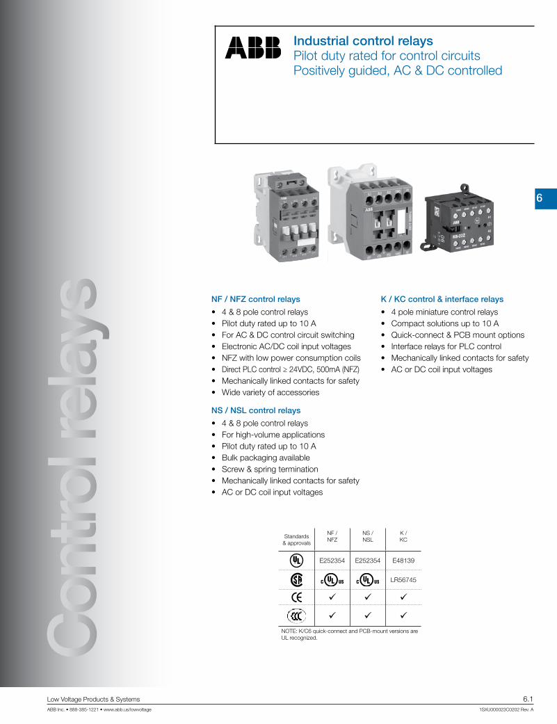
s NF / NFZ control relays
• 4 & 8 pole control relays• Pilot duty rated up to 10 A• For AC & DC control circuit switching• Electronic AC/DC coil input voltages• NFZ with low power consumption coils• Direct PLC control ≥ 24VDC, 500mA (NFZ)• Mechanically linked contacts for safety• Wide variety of accessories
NS / NSL control relays
• 4 & 8 pole control relays• For high-volume applications• Pilot duty rated up to 10 A• Bulk packaging available• Screw & spring termination• Mechanically linked contacts for safety• AC or DC coil input voltages
K / KC control & interface relays
• 4 pole miniature control relays• Compact solutions up to 10 A• Quick-connect & PCB mount options• Interface relays for PLC control• Mechanically linked contacts for safety• AC or DC coil input voltages
Standards& approvals
NF /NFZ
NS /NSL
K /KC
RE252354 E252354 E48139
LR56745
NOTE: K/C6 quick-connect and PCB-mount versions are UL recognized.

6
Control re
lays
6.2 Low Voltage Products & Systems
1SXU000023C0202 Rev. A ABB Inc. • 888-385-1221 • www.abb.us/lowvoltage
Mini control relays – 4 pole Control relays – 4 pole
IEC AC-15 Rated operational current 400 V A 3 3 3
UL/CSA Pilot duty A 600 A 600, Q 300 A 600, Q 600
2 2 3 1 4 0 2 2 3 1 4 0 2 2 3 1 4 0
AC Control supply Type K6-22Z K6-31Z K6-40E NS22E
NS22ESNS31E
NS31ESNS40E
NS40ESNF22E
NFZ22ENF31E
NFZ31ENF40E
NFZ40E
DC Control supply Type KC6-22Z KC6-31Z KC6-0E NSL22E
NSL22ESNSL31E
NSL31ESNSL40E
NSL40ESNF22E
NFZ22ENF31E
NFZ31ENF40E
NFZ40E
AC / DC Control supply Type — — — — — —NF22E
NFZ22ENF31E
NFZ31ENF40E
NFZ40E
See pages 6.12...6.14 See pages 6.10...6.11 See pages 6.8...6.9
Control relays
Control relays – 8 pole
IEC AC-15 Rated operational current 400 V A — 3 3
UL/CSA Pilot duty — A 600, Q 300 A 600, Q 600
4 4 5 3 6 2 7 1 8 0 4 4 5 3 6 2 7 1 8 0
AC Control supply Type — — — NS44E
NS44ESNS53E
NS53ESNS62E
NS62ESNS71E
NS71ESNS80E
NS80ESNF44E
NFZ44ENF53E
NFZ53ENF62E
NFZ62ENF71E
NFZ71ENF80E
NFZ80E
DC Control supply Type — — — NSL44E
NSL44ESNSL53E
NSL53ESNSL62E
NSL62ESNSL71E
NSL71ESNSL80E
NSL80ESNF44E
NFZ44ENF53E
NFZ53ENF62E
NFZ62ENF71E
NFZ71ENF80E
NFZ80E
AC / DC Control supply Type — — — — — — — —NF44E
NFZ44ENF53E
NFZ53ENF62E
NFZ62ENF71E
NFZ71ENF80E
NFZ80E
See pages 6.10...6.11 See pages 6.8...6.9
General informationPanorama

6
Control relays
Low Voltage Products & Systems 6.3ABB Inc. • 888-385-1221 • www.abb.us/lowvoltage 1SXU000023C0202 Rev. A
Mini control relays – 4 pole Control relays – 4 pole
IEC AC-15 Rated operational current 400 V A 3 3 3
UL/CSA Pilot duty A 600 A 600, Q 300 A 600, Q 600
2 2 3 1 4 0 2 2 3 1 4 0 2 2 3 1 4 0
AC Control supply Type K6-22Z K6-31Z K6-40E NS22E
NS22ESNS31E
NS31ESNS40E
NS40ESNF22E
NFZ22ENF31E
NFZ31ENF40E
NFZ40E
DC Control supply Type KC6-22Z KC6-31Z KC6-0E NSL22E
NSL22ESNSL31E
NSL31ESNSL40E
NSL40ESNF22E
NFZ22ENF31E
NFZ31ENF40E
NFZ40E
AC / DC Control supply Type — — — — — —NF22E
NFZ22ENF31E
NFZ31ENF40E
NFZ40E
See pages 6.12...6.14 See pages 6.10...6.11 See pages 6.8...6.9
Control relays – 8 pole
IEC AC-15 Rated operational current 400 V A — 3 3
UL/CSA Pilot duty — A 600, Q 300 A 600, Q 600
4 4 5 3 6 2 7 1 8 0 4 4 5 3 6 2 7 1 8 0
AC Control supply Type — — — NS44E
NS44ESNS53E
NS53ESNS62E
NS62ESNS71E
NS71ESNS80E
NS80ESNF44E
NFZ44ENF53E
NFZ53ENF62E
NFZ62ENF71E
NFZ71ENF80E
NFZ80E
DC Control supply Type — — — NSL44E
NSL44ESNSL53E
NSL53ESNSL62E
NSL62ESNSL71E
NSL71ESNSL80E
NSL80ESNF44E
NFZ44ENF53E
NFZ53ENF62E
NFZ62ENF71E
NFZ71ENF80E
NFZ80E
AC / DC Control supply Type — — — — — — — —NF44E
NFZ44ENF53E
NFZ53ENF62E
NFZ62ENF71E
NFZ71ENF80E
NFZ80E
See pages 6.10...6.11 See pages 6.8...6.9
General informationPanorama
6
Control re
lays
6.4 Low Voltage Products & Systems
1SXU000023C0202 Rev. A ABB Inc. • 888-385-1221 • www.abb.us/lowvoltage
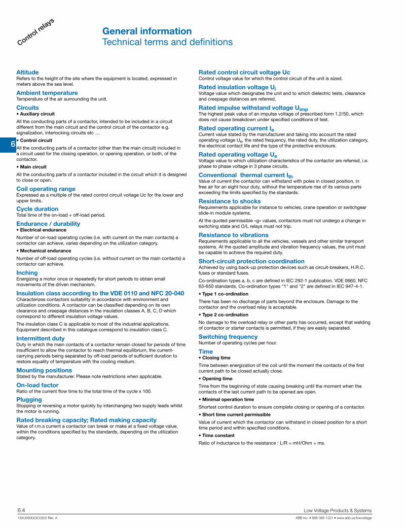
AltitudeRefers to the height of the site where the equipment is located, expressed in meters above the sea level.
Ambient temperatureTemperature of the air surrounding the unit.
Circuits• Auxiliary circuit
All the conducting parts of a contactor, intended to be included in a circuit different from the main circuit and the control circuit of the contactor e.g. signalization, interlocking circuits etc …
• Control circuit
All the conducting parts of a contactor (other than the main circuit) included in a circuit used for the closing operation, or opening operation, or both, of the contactor.
• Main circuit
All the conducting parts of a contactor included in the circuit which it is designed to close or open.
Coil operating rangeExpressed as a multiple of the rated control circuit voltage Uc for the lower and upper limits.
Cycle duration Total time of the on-load + off-load period.
Endurance / durability• Electrical endurance
Number of on-load operating cycles (i.e. with current on the main contacts) a contactor can achieve, varies depending on the utilization category.
• Mechanical endurance
Number of off-load operating cycles (i.e. without current on the main contacts) a contactor can achieve.
InchingEnergizing a motor once or repeatedly for short periods to obtain small movements of the driven mechanism.
Insulation class according to the VDE 0110 and NFC 20-040Characterizes contactors suitability in accordance with environment and utilization conditions. A contactor can be classified depending on its own clearance and creepage distances in the insulation classes A, B, C, D which correspond to different insulation voltage values.
The insulation class C is applicable to most of the industrial applications. Equipment described in this catalogue correspond to insulation class C.
Intermittent dutyDuty in which the main contacts of a contactor remain closed for periods of time insufficient to allow the contactor to reach thermal equilibrium, the current-carrying periods being separated by off-load periods of sufficient duration to restore equality of temperature with the cooling medium.
Mounting positionsStated by the manufacturer. Please note restrictions when applicable.
On-load factorRatio of the current flow time to the total time of the cycle x 100.
PluggingStopping or reversing a motor quickly by interchanging two supply leads whilst the motor is running.
Rated breaking capacity; Rated making capacityValue of r.m.s current a contactor can break or make at a fixed voltage value, within the conditions specified by the standards, depending on the utilization category.
General informationTechnical terms and definitions
Rated control circuit voltage UcControl voltage value for which the control circuit of the unit is sized.
Rated insulation voltage UiVoltage value which designates the unit and to which dielectric tests, clearance and creepage distances are referred.
Rated impulse withstand voltage UimpThe highest peak value of an impulse voltage of prescribed form 1.2/50, which does not cause breakdown under specified conditions of test.
Rated operating current IeCurrent value stated by the manufacturer and taking into account the rated operating voltage Ue, the rated frequency, the rated duty, the utilization category, the electrical contact life and the type of the protective enclosure.
Rated operating voltage UeVoltage value to which utilization characteristics of the contactor are referred, i.e. phase to phase voltage in 3 phase circuits.
Conventional thermal current IthValue of current the contactor can withstand with poles in closed position, in free air for an eight hour duty, without the temperature rise of its various parts exceeding the limits specified by the standards.
Resistance to shocksRequirements applicable for instance to vehicles, crane operation or switchgear slide-in module systems.
At the quoted permissible «g» values, contactors must not undergo a change in switching state and O/L relays must not trip.
Resistance to vibrationsRequirements applicable to all the vehicles, vessels and other similar transport systems. At the quoted amplitude and vibration frequency values, the unit must be capable to achieve the required duty.
Short-circuit protection coordinationAchieved by using back-up protection devices such as circuit-breakers, H.R.C. fuses or standard fuses.
Co-ordination types a, b, c are defined in IEC 292-1 publication, VDE 0660, NFC 63-650 standards. Co-ordination types "1" and "2" are defined in IEC 947-4-1.
• Type 1 co-ordination
There has been no discharge of parts beyond the enclosure. Damage to the contactor and the overload relay is acceptable.
• Type 2 co-ordination
No damage to the overload relay or other parts has occurred, except that welding of contactor or starter contacts is permitted, if they are easily separated.
Switching frequencyNumber of operating cycles per hour.
Time• Closing time
Time between energization of the coil until the moment the contacts of the first current path to be closed actually close.
• Opening time
Time from the beginning of state causing breaking until the moment when the contacts of the last current path to be opened are open.
• Minimal operation time
Shortest control duration to ensure complete closing or opening of a contactor.
• Short time current permissible
Value of current which the contactor can withstand in closed position for a short time period and within specified conditions.
• Time constant
Ratio of inductance to the resistance : L/R = mH/Ohm = ms.

6
Control relays
Low Voltage Products & Systems 6.5ABB Inc. • 888-385-1221 • www.abb.us/lowvoltage 1SXU000023C0202 Rev. A
General informationIEC Standards, utilization categories
Standards• IEC standards 158-1: “Contactors” and series IEC 292 :
“Motor-starters” have been revised and replaced by the new IEC 947-4-1 (1990-05): “Contactors and Motor-starters” referring to IEC 947-1 (1988): “General rules”
The new standards will constitute the basis of the future European and National standards, not yet revised.
Therefore the ratings indicated in this catalog are established according to the former and the future standards.
• Main changes and additions in the new standards are:
• Revision and extension of the utilization categories (see hereafter)
• Replacement of the coordination classes types a, b, c by new types: “1” (approximately equivalent to former class “a”) and “2” (approximately equivalent to former class “c”) with additional requirements.
• Classification of the thermal overload relays in tripping classes: 10 A; 10; 20 and 30 depending on their tripping times, at 1.5 and 7.2 times their setting current, in order to cover motor applications depending on their starting times. Class 10 A is adapted for motors according to IEC 34-1.
• Introduction of tests to verify the connecting capability and the mechanical strength of terminals.
Utilization categories
A contactor duty is characterized by the utilization category plus indication of the rated operating voltage and the rated operating current (see at Rated …), or the motor characteristics.
Utilization categories for contactors according to IEC 947-4-1
Alternating current: AC-1 Non-inductive or slightly inductive loads, resistance furnaces. Power factor 0.7 - 0.8 (slightly inductive). AC-2 Slip-ring motors: starting, switching-off. AC-3 Squirrel-cage motors: starting, switching-off motors during running. Power factor 0.4 - 0.5 (AC-3). AC-4 Squirrel-cage motors: starting, plugging, inching. AC-5a Switching of electric discharge lamp controls. AC-5b Switching of incandescent lamps. AC-6a Switching of transformers. AC-6b Switching of capacitor banks AC-8a Hermetic refrigerant compressor motor control with manual resetting of overload releases AC-8b Hermetic refrigerant compressor motor control with automatic resetting of overload releases.
Direct current: DC-1 Non-inductive or slightly inductive loads, resistance furnaces. DC-3 Shunt motors: starting, plugging, inching. Dynamic breaking of d.c. motors. DC-5 Series motors: starting, plugging, inching. Dynamic breaking of d.c. motors. DC-6 Switching of incandescent lamps
Alternating current: AC-12 Control of resistive loads and solid state loads with isolation by opto couplers. AC-13 Control of solid state loads with transformer isolation. AC-14 Control of small electromagnetic loads (≤ 72 VA). AC-15 Control of electromagnetic loads (> 72 VA).
Direct current: DC-12 Control of resistive loads and solid state loads with isolation by opto couplers. DC-13 Control of electromagnets. DC-14 Control of electromagnetic loads having economy resistors in circuit.
Utilization categories for contactor relays according to IEC 947-5-1
Utilization categories AC-1, AC-2, AC-3, AC-4 and DC-1, DC-3, DC-5 are maintained with slightly more severe tests.
Other categories have been added in order to standardize specific applications. In fact some contactor applications and the specific criteria characterizing the types of load controlled can modify the recommended utilization characteristics. These major applications are, for example :
Switching of capacitor banksThis application is characterized by high current peaks when switching-on the contactor and presence of harmonic currents on uninterrupted duty. For this application, IEC 947-4-1 has defined an utilization category AC-6b. Practical ratings have to be defined according to tests or, in absence of tests, by a calculation indicated in IEC 947-4-1.
Switching of transformersThis application is characterized by high current peaks on contactor closing due to magnetization phenomena. The corresponding utilization category according to IEC 947-4-1 is AC-6a. Ratings are derived from test-values for AC-3 or AC-4 according to formula given in IEC 947-4-1.
Switching of lighting circuitsThe current peaks on contactor closing and power factor vary depending on the type of lamps, the switching method used and if compensation systems are fitted or not.
IEC 947-4-1 contains two standard utilization categories
AC-5a for switching of the electric discharge lamps. AC-5b for switching of incandescent lamp.

6
Control re
lays
6.6 Low Voltage Products & Systems
1SXU000023C0202 Rev. A ABB Inc. • 888-385-1221 • www.abb.us/lowvoltage
General informationPilot duty ratings and overload trip classes
Pilot duty ratings for AC control circuit contacts
Contact rating
designation
Continuous thermal, test current (A)
Maximum current, 50/60 Hz (A)
120 v ac 240 v ac 480 v ac 600 v ac Volt-amperes
Make Break Make Break Make Break Make Break Make Break
A150 10 60 6.00 - - - - - - 7200 720
A300 10 60 6.00 30 3.00 - - - - 7200 720
A600 10 60 6.00 30 3.00 15 1.50 12 1.20 7200 720
B150 5 30 3.00 - - - - - - 3600 360
B300 5 30 3.00 15 1.50 - - - - 3600 360
B600 5 30 3.00 15 1.50 7.5 0.75 6 0.60 3600 360
C150 2.5 15 1.5 - - - - - - 1800 180
C300 2.5 15 1.5 7.5 0.75 - - - - 1800 180
C600 2.5 15 1.5 7.5 0.75 3.75 0.375 3.00 0.30 1800 180
D150 1.0 3.60 0.60 - - - - - - 432 72
D300 1.0 3.60 0.60 1.80 0.30 - - - - 432 72
E150 0.5 1.80 0.30 - - - - - - 216 36
Mechanical switching ratings and test values as published in Table 1-4-1 of NEMA ICS 5-2000 (R2005, R2010)
Pilot duty ratings for DC control circuit contacts
Contact rating
designation
Continuous thermal, test current (A)
Maximum current, 50/60 Hz (A)
120 v dc 250 v dc 301 to 600 v dc Volt-amperes
Make / Break Make / Break Make / Break Make / Break
N150 10 2.2 - - 275
N300 10 2.2 1.1 - 275
N600 10 2.2 1.1 0.40 275
P150 5.0 1.1 - - 138
P300 5.0 1.1 0.55 - 138
P600 5.0 1.1 0.55 0.20 138
Q150 2.5 0.55 - - 69
Q300 2.5 0.55 0.27 - 69
Q600 2.5 0.55 0.27 0.10 69
R150 1.0 0.22 - - 28
R300 1.0 0.22 0.11 - 28
Mechanical switching ratings and test values as published in Table 1-4-1 of NEMA ICS 5-2000 (R2005, R2010)
Pilot duty rating explanation
A - 600Max. thermalcurrent
Max. voltage

6
Control relays
Low Voltage Products & Systems 6.7ABB Inc. • 888-385-1221 • www.abb.us/lowvoltage 1SXU000023C0202 Rev. A
General informationNF/NFZ control relays4 & 8 pole
DescriptionNF / NFZ control relays are provided in either four or eight auxiliary pole configu-rations with a variety of accessories including additional auxiliary contacts and electronic timers.
ApplicationNF / NFZ control relays are pilot duty rated and primarily used for switching both AC and DC control circuits.
Control circuit typesNF / NFZ coils are designed to utilize both AC (50/60 Hz) and DC control circuit inputs ranging from 12…500V. Surge suppression is included. NFZ types offer low power consumption coils.
Control relay types4-pole: NF(Z)22E, NF(Z)31E, NF(Z)40E
8-pole: NF(Z)44E, NF(Z)53E, NF(Z)62E NF(Z)71E, NF(Z)80E
Quick DIN-rail mount & dismount, no tools required• 35 x 7.5mm &• 35 x 15mm
Integral surge suppression
Actuator for side-mount accessories
Contoured sides for easy access to panel mounting holes
Terminals on NF / NFZ control relays are delivered in open position with captive screws (screws of unused terminals must be tightened)
IP20 degree protection according to IEC/EN 60947-1; protection from live parts according to VDE0106 Part. 100.
Detachable coil terminals• Can be pre-wired prior to installation• Can easily be rotated from top (standard) to bottom
Front-mount coil termination available (4-pole only)
Stops for attaching front-mount accessories (4-pole only)
Function markers included as standard on NF / NFZ control relays
Clear indication of coil voltages and frequencies
Terminal screws:• Posidrive (+,-) No 2
Catalog number explanationFor reference only – not all combinations will produce
valid catalog numbers
NF 31 E - 13
Control relay type Coil voltage code(see product selection pages)
Control relay type• 22 = 2 NO / 2 NC• 31 = 3 NO / 1 NC• 40 = 4 NO• 44 = 4 NO / 4 NC• 53 = 5 NO / 3 NC• 62 = 6 NO / 2 NC• 71 = 7 NO / 1 NC• 80 = 8 NO

6
Control re
lays
6.8 Low Voltage Products & Systems
1SXU000023C0202 Rev. A ABB Inc. • 888-385-1221 • www.abb.us/lowvoltage
NF22E
NF44E
Description – NF control relays include an electronic coil interface accepting a wide control voltage Uc min. ... Uc max.
Only four coils cover control voltages between 24...500 V 50/60 Hz or 20...500 V DC – NF control relays can manage large control voltage variations. One coil (i.e. 100...250 V 50/60 Hz - DC) can be used for
different control voltages used worldwide without any coil change – NF control relays have built-in surge protection and do not require additional surge suppressors – The control relays have mechanically-linked auxiliary contacts compliant with Annex L of IEC 60947-5-1 and include the
"Mechanically Linked" symbol on their side – 8-pole control relays are mounted with a non-removable auxiliary contact block (2nd stack).
Ordering DetailsNumber of contacts Control voltage
Catalog number
1st stack 2nd stack Range
Uc min. ... Uc max.
V 50/60 Hz V DC
43NO
NO44
31NC
NC32
21NC
NC22
13NO
NO14
A1
A2
2 NO / 2 NC
24...60 20...60 NF22E-1148...130 48...130 NF22E-12100...250 100...250 NF22E-13250...500 250...500 NF22E-14
33NO
NO34
21NC
NC22
13NO
NO14
43NO
NO44
A1
A2
3 NO / 1 NC
24...60 20...60 NF31E-1148...130 48...130 NF31E-12100...250 100...250 NF31E-13250...500 250...500 NF31E-14
43NO
NO44
33NO
NO34
23NO
NO24
13NO
NO14
A1
A2
4 NO
24...60 20...60 NF40E-1148...130 48...130 NF40E-12100...250 100...250 NF40E-13250...500 250...500 NF40E-14
43NO
NO44
33NO
NO34
23NO
NO24
13NO
NO14
81NC
NC82
71NC
NC72
61NC
NC62
51NC
NC52
A1
A2
4 NO / 4 NC
24...60 20...60 NF44E-1148...130 48...130 NF44E-12100...250 100...250 NF44E-13250...500 250...500 NF44E-14
43NO
NO44
33NO
NO34
23NO
NO24
13NO
NO14
81NC
NC82
71NC
NC72
61NC
NC62
53NO
NO54
A1
A2
5 NO / 3 NC
24...60 20...60 NF53E-1148...130 48...130 NF53E-12100...250 100...250 NF53E-13250...500 250...500 NF53E-14
43NO
NO44
33NO
NO34
23NO
NO24
13NO
NO14
83NO
NO84
71NC
NC72
61NC
NC62
53NO
NO54
A1
A2
6 NO / 2 NC
24...60 20...60 NF62E-1148...130 48...130 NF62E-12100...250 100...250 NF62E-13250...500 250...500 NF62E-14
43NO
NO44
33NO
NO34
23NO
NO24
13NO
NO14
83NO
NO84
73NO
NO74
61NC
NC62
53NO
NO54
A1
A2
7 NO / 1 NC
24...60 20...60 NF71E-1148...130 48...130 NF71E-12100...250 100...250 NF71E-13250...500 250...500 NF71E-14
43NO
NO44
33NO
NO34
23NO
NO24
13NO
NO14
83NO
NO84
73NO
NO74
63NO
NO64
53NO
NO54
A1
A2
8 NO
24...60 20...60 NF80E-1148...130 48...130 NF80E-12100...250 100...250 NF80E-13250...500 250...500 NF80E-14
NF, 4 & 8 poleFor pilot duty applications up to 10 AElectronic AC/DC operated coils
45 1.77"
80 3
.15"
6 0
.24"
77 3.03"
71 2.80"
5.5 0.22"
35 m
m E
N/IE
C 60
715
10 0.39"
5.5 0.22"
35 1.38"
70 2
.76"
60 2
.36"
5 0
.20"
5 0.20"
ø 4.2 0.17"2 x
M4 8-32 UNC35 1.38"
70 2
.76"
60 2
.36"
5 0
.20"
5 0.20"
ø 4.2 0.17"2 x
M4 8-32 UNC
45 1.77"
80 3
.15"
6 0
.24"
110.5 4.35"
71 2.80"
5.5 0.22"
35 m
m E
N/IE
C 60
715
10 0.39"
5.5 0.22"
43 1
.69"
Main dimensions mm, inches
NF...22E, NF...31E, NF...40E NF...44E, NF...53E, NF...62E, NF...71E, NF...80E

6
Control relays
Low Voltage Products & Systems 6.9ABB Inc. • 888-385-1221 • www.abb.us/lowvoltage 1SXU000023C0202 Rev. A
Description – NFZ control relays include an electronic coil interface accepting a wide control voltage Uc min. ... Uc max. and managing
large control voltage variations. NFZ control relays cover control voltages between 24...250 V 50/60 Hz or 12...250 V DC – NFZ control relays allow direct control by PLC-output ≥ 24 V DC 500 mA and obtain a reduced holding coil consumption.
NFZ control relays withstand short dips and voltage interruptions (SEMI F47-0706 compliance) – NFZ control relays have built-in surge protection and do not require additional surge suppressors – The control relays have mechanically-linked auxiliary contacts compliant with Annex L of IEC 60947-5-1 and include the
"Mechanically Linked" symbol on their side – 8-pole control relays are mounted with a non-removable auxiliary contact block (2nd stack).
Ordering Details
Number of contacts Control voltage
Catalog number
1st stack 2nd stack Range
Uc min. ... Uc max.
V 50/60 Hz V DC
43NO
NO44
31NC
NC32
21NC
NC22
13NO
NO14
A1
A2
2 NO / 2 NC
- 12...20 NFZ22E-2024...60 20...60 NFZ22E-2148...130 48...130 NFZ22E-22100...250 100...250 NFZ22E-23
33NO
NO34
21NC
NC22
13NO
NO14
43NO
NO44
A1
A2
3 NO / 1 NC
- 12...20 NFZ31E-2024...60 20...60 NFZ31E-2148...130 48...130 NFZ31E-22100...250 100...250 NFZ31E-23
43NO
NO44
33NO
NO34
23NO
NO24
13NO
NO14
A1
A2
4 NO
- 12...20 NFZ40E-2024...60 20...60 NFZ40E-2148...130 48...130 NFZ40E-22100...250 100...250 NFZ40E-23
43NO
NO44
33NO
NO34
23NO
NO24
13NO
NO14
81NC
NC82
71NC
NC72
61NC
NC62
51NC
NC52
A1
A2
4 NO / 4 NC
- 12...20 NFZ44E-2024...60 20...60 NFZ44E-2148...130 48...130 NFZ44E-22100...250 100...250 NFZ44E-23
43NO
NO44
33NO
NO34
23NO
NO24
13NO
NO14
81NC
NC82
71NC
NC72
61NC
NC62
53NO
NO54
A1
A2
5 NO / 3 NC
- 12...20 NFZ53E-2024...60 20...60 NFZ53E-2148...130 48...130 NFZ53E-22100...250 100...250 NFZ53E-23
43NO
NO44
33NO
NO34
23NO
NO24
13NO
NO14
83NO
NO84
71NC
NC72
61NC
NC62
53NO
NO54
A1
A2
6 NO / 2 NC
- 12...20 NFZ62E-2024...60 20...60 NFZ62E-2148...130 48...130 NFZ62E-22100...250 100...250 NFZ62E-23
43NO
NO44
33NO
NO34
23NO
NO24
13NO
NO14
83NO
NO84
73NO
NO74
61NC
NC62
53NO
NO54
A1
A2
7 NO / 1 NC
- 12...20 NFZ71E-2024...60 20...60 NFZ71E-2148...130 48...130 NFZ71E-22100...250 100...250 NFZ71E-23
43NO
NO44
33NO
NO34
23NO
NO24
13NO
NO14
83NO
NO84
73NO
NO74
63NO
NO64
53NO
NO54
A1
A2
8 NO
- 12...20 NFZ80E-2024...60 20...60 NFZ80E-2148...130 48...130 NFZ80E-22100...250 100...250 NFZ80E-23
NFZ22E
NFZ44E
NFZ, 4 & 8 poleFor pilot duty applications up to 10 ALow power consumption, electronic AC/DC operated coils
45 1.77"
80 3
.15"
6 0
.24"
77 3.03"
71 2.80"
5.5 0.22"
35 m
m E
N/IE
C 60
715
10 0.39"
5.5 0.22"
35 1.38"
70 2
.76"
60 2
.36"
5 0
.20"
5 0.20"
ø 4.2 0.17"2 x
M4 8-32 UNC35 1.38"
70 2
.76"
60 2
.36"
5 0
.20"
5 0.20"
ø 4.2 0.17"2 x
M4 8-32 UNC
45 1.77"
80 3
.15"
6 0
.24"
110.5 4.35"
71 2.80"
5.5 0.22"
35 m
m E
N/IE
C 60
715
10 0.39"
5.5 0.22"
43 1
.69"
Main dimensions mm, inches

6
Control re
lays
6.10 Low Voltage Products & Systems
1SXU000023C0202 Rev. A ABB Inc. • 888-385-1221 • www.abb.us/lowvoltage
NS/NSL 4 & 8 poleFor pilot duty applications up to 10 AAC or DC operated coils, bulk packaged for high volume
Description
NS/NSL contactor relays are used for switching auxiliary and control circuits.
These contactor relays are designed with: • 4 poles or 8 poles. Contactor relays have mechanically linked auxiliary contact elements (side-marked symbol) • Suitable for direct PLC control (DC 3W) • add-on auxiliary contact blocks for front mounting and a comprehensive range of accessories.
Ordering detailsNumber of contacts
Rated control circuit voltage
Uc
Catalognumber,
AC controlled
Rated control circuit voltage
Uc
Catalognumber,
DC controlled
1st stack 2nd stack
V 50 Hz V 60 Hz V-DC
43NO
NO44
31NC
NC32
21NC
NC22
13NO
NO14
A1
A2
2 NO / 2 NC
24 24 NS22E-20M 24 NSL22E-81M- 120 NS22E-16M 48 NSL22E-83M
230 230 NS22E-26M 110 NSL22E-86M400 400 NS22E-28M 220 NSL22E-88M
33NO
NO34
21NC
NC22
13NO
NO14
43NO
NO44
A1
A2
3 NO / 1 NC
24 24 NS31E-20M 24 NSL31E-81M- 120 NS31E-16M 48 NSL31E-83M
230 230 NS31E-26M 110 NSL31E-86M400 400 NS31E-28M 220 NSL31E-88M
43NO
NO44
33NO
NO34
23NO
NO24
13NO
NO14
A1
A2
4 NO
24 24 NS40E-20M 24 NSL40E-81M- 120 NS40E-16M 48 NSL40E-83M
230 230 NS40E-26M 110 NSL40E-86M400 400 NS40E-28M 220 NSL40E-88M
43NO
NO44
33NO
NO34
23NO
NO24
13NO
NO14
81NC
NC82
71NC
NC72
61NC
NC62
51NC
NC52
A1
A2
4 NO / 4 NC
24 24 NS44E-20M 24 NSL44E-81M- 120 NS44E-16M 48 NSL44E-83M
230 230 NS44E-26M 110 NSL44E-86M400 400 NS44E-28M 220 NSL44E-88M
43NO
NO44
33NO
NO34
23NO
NO24
13NO
NO14
81NC
NC82
71NC
NC72
61NC
NC62
53NO
NO54
A1
A2
5 NO / 3 NC
24 24 NS53E-20M 24 NSL53E-81M- 120 NS53E-16M 48 NSL53E-83M
230 230 NS53E-26M 110 NSL53E-86M400 400 NS53E-28M 220 NSL53E-88M
43NO
NO44
33NO
NO34
23NO
NO24
13NO
NO14
83NO
NO84
71NC
NC72
61NC
NC62
53NO
NO54
A1
A2
6 NO / 2 NC
24 24 NS62E-20M 24 NSL62E-81M- 120 NS62E-16M 48 NSL62E-83M
230 230 NS62E-26M 110 NSL62E-86M400 400 NS62E-28M 220 NSL62E-88M
43NO
NO44
33NO
NO34
23NO
NO24
13NO
NO14
83NO
NO84
73NO
NO74
61NC
NC62
53NO
NO54
A1
A2
7 NO / 1 NC
24 24 NS71E-20M 24 NSL71E-81M- 120 NS71E-16M 48 NSL71E-83M
230 230 NS71E-26M 110 NSL71E-86M400 400 NS71E-28M 220 NSL71E-88M
43NO
NO44
33NO
NO34
23NO
NO24
13NO
NO14
83NO
NO84
73NO
NO74
63NO
NO64
53NO
NO54
A1
A2
8 NO
24 24 NS80E-20M 24 NSL80E-81M- 120 NS80E-16M 48 NSL80E-83M
230 230 NS80E-26M 110 NSL80E-86M400 400 NS80E-28M 220 NSL80E-88M
NOTE: For DC operated devices, the polarity of A1+ and A2- must be respected.
Main dimensions mm, inches
72.5 2.85"
45 1.77"
68 2
.68" 5.5 0.22"
7 0.28"
35 m
m E
N/IE
C 60
715
50 1
.97"
60 2
.36"
45 1.77"
68 2
.68"
72.5 2.85"
5.5 0.22"
7 0.28"
35 m
m E
N/IE
C 60
715
100.2 3.94"
44.2
1.7
4"
35 1.38"
ø 4.2 0.17"
2 x M4 8-32 UNC
NS22E, NS31E, NS40E NS44E, NS53E, NS62E, NS71E, NS80E
4 pole
8 pole
Standard bulk pack quantities (M)
Control relays Quantity
NS/L22E NS/L31E NS/L40E
40
NS/L44E NS/L53E NS/L62E NS/L71E NS/L80E
20
Additional coil voltage codesAC voltages Coil
codeV - 50 Hz V - 60 Hz
42 42 21
48 48 22
110 110 23
115 115 24
220 220 25
240 240 27
- 277 17
380 - 13
415 415 29
DC voltages Coil codeV - DC
12 80
60 84
125 87
240 89

6
Control relays
Low Voltage Products & Systems 6.11ABB Inc. • 888-385-1221 • www.abb.us/lowvoltage 1SXU000023C0202 Rev. A
NS/NSL 4 & 8 pole, spring terminatedFor pilot duty applications up to 10 AAC or DC operated coils, bulk packaged for high volume
Description
NS/NSL contactor relays are used for switching auxiliary and control circuits.
These contactor relays are designed with: • 4 poles or 8 poles. Contactor relays have mechanically linked auxiliary contact elements (side-marked symbol) • Suitable for direct PLC control (DC 3W) • add-on auxiliary contact blocks for front mounting and a comprehensive range of accessories.
Ordering detailsNumber of contacts Rated control
circuit voltageUc
Catalognumber,
AC controlled
Rated control circuit voltage
Uc
Catalognumber,
DC controlled1st stack 2nd stack
V 50 Hz V 60 Hz V-DC
43NO
NO44
31NC
NC32
21NC
NC22
13NO
NO14
A1+
A2-
2 NO / 2 NC
24 24 NS22ES-20M 24 NSL22ES-81M- 120 NS22ES-16M 48 NSL22ES-83M
230 230 NS22ES-26M 110 NSL22ES-86M400 400 NS22ES-28M 220 NSL22ES-88M
33NO
NO34
21NC
NC22
13NO
NO14
43NO
NO44
A1+
A2-
3 NO / 1 NC
24 24 NS31ES-20M 24 NSL31ES-81M- 120 NS31ES-16M 48 NSL31ES-83M
230 230 NS31ES-26M 110 NSL31ES-86M400 400 NS31ES-28M 220 NSL31ES-88M
43NO
NO44
33NO
NO34
23NO
NO24
13NO
NO14
A1+
A2-
4 NO
24 24 NS40ES-20M 24 NSL40ES-81M- 120 NS40ES-16M 48 NSL40ES-83M
230 230 NS40ES-26M 110 NSL40ES-86M400 400 NS40ES-28M 220 NSL40ES-88M
43NO
NO44
33NO
NO34
23NO
NO24
13NO
NO14
81NC
NC82
71NC
NC72
61NC
NC62
51NC
NC52
A1+
A2-
4 NO / 4 NC
24 24 NS44ES-20M 24 NSL44ES-81M- 120 NS44ES-16M 48 NSL44ES-83M
230 230 NS44ES-26M 110 NSL44ES-86M400 400 NS44ES-28M 220 NSL44ES-88M
43NO
NO44
33NO
NO34
23NO
NO24
13NO
NO14
81NC
NC82
71NC
NC72
61NC
NC62
53NO
NO54
A1+
A2-
5 NO / 3 NC
24 24 NS53ES-20M 24 NSL53ES-81M- 120 NS53ES-16M 48 NSL53ES-83M
230 230 NS53ES-26M 110 NSL53ES-86M400 400 NS53ES-28M 220 NSL53ES-88M
43NO
NO44
33NO
NO34
23NO
NO24
13NO
NO14
83NO
NO84
71NC
NC72
61NC
NC62
53NO
NO54
A1+
A2-
6 NO / 2 NC
24 24 NS62ES-20M 24 NSL62ES-81M- 120 NS62ES-16M 48 NSL62ES-83M
230 230 NS62ES-26M 110 NSL62ES-86M400 400 NS62ES-28M 220 NSL62ES-88M
43NO
NO44
33NO
NO34
23NO
NO24
13NO
NO14
83NO
NO84
73NO
NO74
61NC
NC62
53NO
NO54
A1+
A2-
7 NO / 1 NC
24 24 NS71ES-20M 24 NSL71ES-81M- 120 NS71ES-16M 48 NSL71ES-83M
230 230 NS71ES-26M 110 NSL71ES-86M400 400 NS71ES-28M 220 NSL71ES-88M
43NO
NO44
33NO
NO34
23NO
NO24
13NO
NO14
83NO
NO84
73NO
NO74
63NO
NO64
53NO
NO54
A1+
A2-
8 NO
24 24 NS80ES-20M 24 NSL80ES-81M- 120 NS80ES-16M 48 NSL80ES-83M
230 230 NS80ES-26M 110 NSL80ES-86M400 400 NS80ES-28M 220 NSL80ES-88M
NOTE: For DC operated devices, the polarity of A1+ and A2- must be respected.
Main dimensions mm, inches
NSL22E, NSL31E, NSL40E NSL44E, NSL53E, NSL62E, NSL71E, NSL80E
4 pole
8 pole
Standard bulk pack quantities (M)
Control relays Quantity
NS/L22ES NS/L31ES NS/L40ES
40
NS/L44ES NS/L53ES NS/L62ES NS/L71ES NS/L80ES
20
Additional coil voltage codesAC voltages Coil
codeV - 50 Hz V - 60 Hz
42 42 21
48 48 22
110 110 23
115 115 24
220 220 25
240 240 27
- 277 17
380 - 13
415 415 29
DC voltages Coil codeV - DC
12 80
60 84
125 87
240 89
72.5 2.85"
45 1.77"
68 2
.68" 5.5 0.22"
7 0.28"
35 m
m E
N/IE
C 60
715
45 1.77"
68 2
.68"
72.5 2.85"
5.5 0.22"
7 0.28"
35 m
m E
N/IE
C 60
715
110.8 4.36"
35.4
1.3
9"

6
Control re
lays
6.12 Low Voltage Products & Systems
1SXU000023C0202 Rev. A ABB Inc. • 888-385-1221 • www.abb.us/lowvoltage
K6 miniature, 4 poleFor compact pilot duty applications up to 10 AAC operated coils
DescriptionThese contactors are designed with:
• 4 poles with various contact combinations• control circuit: AC operated, low coil consumption (3.5 VA at pull-in and at holding)• hum-free coil• add-on auxiliary contact blocks for front or side mounting• designed for rail or wall mounting
Ordering details
Number of contacts
Rated control circuit voltage
UcCatalog number,screw termination
Catalog number,quick-connect
termination
Catalog number,PCB-mounttermination
V-50 Hz V-60 Hz
1 3 5 13 A1
2 4 6 14 A2
A1 13 1 3 5
A2 14 2 4 6
1 3 5 13 A1
2 4 6 14 A2
1 3 5 21 A1
2 4 6 22 A2
B6(7)-40-00 ...BC6(7)-40-00 ...
B6(7)-30-10 ...BC6(7)-30-10 ...
B6(7)-30-01 ...BC6(7)-30-01 ...
VB6(7)-30-10 ...VBC6(7)-30-10 ...
VB6(7)-30-01 ...VBC6(7)-30-01 ...
K6-40 E ...KC6-40 E ...
K6-31 Z ...KC6-31 Z ...
K6-22 Z ...KC6-22 Z ...
Miniature control relays
Miniature mechanically interlocked contactors
Miniature contactors
A1 21 1 3 5
A2 22 2 4 6
1 3 5 7 A1
2 4 6 8 A2
1 3 5 21 A1
2 4 6 22 A2
13 23 33 43 A1
14 24 34 44 A2
13 33 43 21 A1
14 34 44 22 A2
13 43 21 31 A1
14 44 22 32 A2
2 NO / 2 NC
24 24 K6-22Z-01 K6-22Z-F01 K6-22Z-P01
42 42 K6-22Z-02 K6-22Z-F02 K6-22Z-P02
48 48 K6-22Z-03 K6-22Z-F03 K6-22Z-P03
110…127 110…127 K6-22Z-84 K6-22Z-F84 K6-22Z-P84
220…240 220…240 K6-22Z-80 K6-22Z-F80 K6-22Z-P80
380…415 380…415 K6-22Z-85 K6-22Z-F85 K6-22Z-P85
1 3 5 13 A1
2 4 6 14 A2
A1 13 1 3 5
A2 14 2 4 6
1 3 5 13 A1
2 4 6 14 A2
1 3 5 21 A1
2 4 6 22 A2
B6(7)-40-00 ...BC6(7)-40-00 ...
B6(7)-30-10 ...BC6(7)-30-10 ...
B6(7)-30-01 ...BC6(7)-30-01 ...
VB6(7)-30-10 ...VBC6(7)-30-10 ...
VB6(7)-30-01 ...VBC6(7)-30-01 ...
K6-40 E ...KC6-40 E ...
K6-31 Z ...KC6-31 Z ...
K6-22 Z ...KC6-22 Z ...
Miniature control relays
Miniature mechanically interlocked contactors
Miniature contactors
A1 21 1 3 5
A2 22 2 4 6
1 3 5 7 A1
2 4 6 8 A2
1 3 5 21 A1
2 4 6 22 A2
13 23 33 43 A1
14 24 34 44 A2
13 33 43 21 A1
14 34 44 22 A2
13 43 21 31 A1
14 44 22 32 A2
3 NO / 1 NC
24 24 K6-31Z-01 K6-31Z-F01 K6-31Z-P01
42 42 K6-31Z-02 K6-31Z-F02 K6-31Z-P02
48 48 K6-31Z-03 K6-31Z-F03 K6-31Z-P03
110…127 110…127 K6-31Z-84 K6-31Z-F84 K6-31Z-P84
220…240 220…240 K6-31Z-80 K6-31Z-F80 K6-31Z-P80
380…415 380…415 K6-31Z-85 K6-31Z-F85 K6-31Z-P85
1 3 5 13 A1
2 4 6 14 A2
A1 13 1 3 5
A2 14 2 4 6
1 3 5 13 A1
2 4 6 14 A2
1 3 5 21 A1
2 4 6 22 A2
B6(7)-40-00 ...BC6(7)-40-00 ...
B6(7)-30-10 ...BC6(7)-30-10 ...
B6(7)-30-01 ...BC6(7)-30-01 ...
VB6(7)-30-10 ...VBC6(7)-30-10 ...
VB6(7)-30-01 ...VBC6(7)-30-01 ...
K6-40 E ...KC6-40 E ...
K6-31 Z ...KC6-31 Z ...
K6-22 Z ...KC6-22 Z ...
Miniature control relays
Miniature mechanically interlocked contactors
Miniature contactors
A1 21 1 3 5
A2 22 2 4 6
1 3 5 7 A1
2 4 6 8 A2
1 3 5 21 A1
2 4 6 22 A2
13 23 33 43 A1
14 24 34 44 A2
13 33 43 21 A1
14 34 44 22 A2
13 43 21 31 A1
14 44 22 32 A2
4 NO
24 24 K6-40E-01 K6-40E-F01 K6-40E-P01
42 42 K6-40E-02 K6-40E-F02 K6-40E-P02
48 48 K6-40E-03 K6-40E-F03 K6-40E-P03
110…127 110…127 K6-40E-84 K6-40E-F84 K6-40E-P84
220…240 220…240 K6-40E-80 K6-40E-F80 K6-40E-P80
380…415 380…415 K6-40E-85 K6-40E-F85 K6-40E-P85
Main dimensions mm, inches
47.5 1.87"
52.5 2.07"
57.5
2.
26"
42.2
1.
66"
45.2
1.
78"
4.5 0.18"
43.7 1.72"
46.7 1.84"
K6, K6...F
1 0
.04"
47.5 1.87"
42.2
1.
66"
45.2
1.
78"
44.7 1.76"
47.7 1.88" 4.3 0.17"
K6...P
K6
K6...F
K6...P

6
Control relays
Low Voltage Products & Systems 6.13ABB Inc. • 888-385-1221 • www.abb.us/lowvoltage 1SXU000023C0202 Rev. A
KC6 miniature, 4 poleFor compact pilot duty applications up to 10 ADC operated coils
DescriptionThese contactors are designed with:
• 4 poles with various contact combinations• control circuit: DC operated, low coil consumption (3.5 W at pull-in and at holding)• hum-free coil• add-on auxiliary contact blocks for front or side mounting• designed for rail or wall mounting
Ordering details
Number of contacts
Rated control circuit voltage
UcCatalog number,screw termination
Catalog number,quick-connect
termination
Catalog number,PCB-mounttermination
V-DC
1 3 5 13 A1
2 4 6 14 A2
A1 13 1 3 5
A2 14 2 4 6
1 3 5 13 A1
2 4 6 14 A2
1 3 5 21 A1
2 4 6 22 A2
B6(7)-40-00 ...BC6(7)-40-00 ...
B6(7)-30-10 ...BC6(7)-30-10 ...
B6(7)-30-01 ...BC6(7)-30-01 ...
VB6(7)-30-10 ...VBC6(7)-30-10 ...
VB6(7)-30-01 ...VBC6(7)-30-01 ...
K6-40 E ...KC6-40 E ...
K6-31 Z ...KC6-31 Z ...
K6-22 Z ...KC6-22 Z ...
Miniature control relays
Miniature mechanically interlocked contactors
Miniature contactors
A1 21 1 3 5
A2 22 2 4 6
1 3 5 7 A1
2 4 6 8 A2
1 3 5 21 A1
2 4 6 22 A2
13 23 33 43 A1
14 24 34 44 A2
13 33 43 21 A1
14 34 44 22 A2
13 43 21 31 A1
14 44 22 32 A2
2 NO / 2 NC
12 KC6-22Z-07 KC6-22Z-F07 KC6-22Z-P07
24 KC6-22Z-01 KC6-22Z-F01 KC6-22Z-P01
48 KC6-22Z-16 KC6-22Z-F16 KC6-22Z-P16
60 KC6-22Z-13 KC6-22Z-F13 KC6-22Z-P13
110…125 KC6-22Z-04 KC6-22Z-F04 KC6-22Z-P04
220…240 KC6-22Z-05 KC6-22Z-F05 KC6-22Z-P05
1 3 5 13 A1
2 4 6 14 A2
A1 13 1 3 5
A2 14 2 4 6
1 3 5 13 A1
2 4 6 14 A2
1 3 5 21 A1
2 4 6 22 A2
B6(7)-40-00 ...BC6(7)-40-00 ...
B6(7)-30-10 ...BC6(7)-30-10 ...
B6(7)-30-01 ...BC6(7)-30-01 ...
VB6(7)-30-10 ...VBC6(7)-30-10 ...
VB6(7)-30-01 ...VBC6(7)-30-01 ...
K6-40 E ...KC6-40 E ...
K6-31 Z ...KC6-31 Z ...
K6-22 Z ...KC6-22 Z ...
Miniature control relays
Miniature mechanically interlocked contactors
Miniature contactors
A1 21 1 3 5
A2 22 2 4 6
1 3 5 7 A1
2 4 6 8 A2
1 3 5 21 A1
2 4 6 22 A2
13 23 33 43 A1
14 24 34 44 A2
13 33 43 21 A1
14 34 44 22 A2
13 43 21 31 A1
14 44 22 32 A2
3 NO / 1 NC
12 KC6-31Z-07 KC6-31Z-F07 KC6-31Z-P07
24 KC6-31Z-01 KC6-31Z-F01 KC6-31Z-P01
48 KC6-31Z-16 KC6-31Z-F16 KC6-31Z-P16
60 KC6-31Z-13 KC6-31Z-F13 KC6-31Z-P13
110…125 KC6-31Z-04 KC6-31Z-F04 KC6-31Z-P04
220…240 KC6-31Z-05 KC6-31Z-F05 KC6-31Z-P05
1 3 5 13 A1
2 4 6 14 A2
A1 13 1 3 5
A2 14 2 4 6
1 3 5 13 A1
2 4 6 14 A2
1 3 5 21 A1
2 4 6 22 A2
B6(7)-40-00 ...BC6(7)-40-00 ...
B6(7)-30-10 ...BC6(7)-30-10 ...
B6(7)-30-01 ...BC6(7)-30-01 ...
VB6(7)-30-10 ...VBC6(7)-30-10 ...
VB6(7)-30-01 ...VBC6(7)-30-01 ...
K6-40 E ...KC6-40 E ...
K6-31 Z ...KC6-31 Z ...
K6-22 Z ...KC6-22 Z ...
Miniature control relays
Miniature mechanically interlocked contactors
Miniature contactors
A1 21 1 3 5
A2 22 2 4 6
1 3 5 7 A1
2 4 6 8 A2
1 3 5 21 A1
2 4 6 22 A2
13 23 33 43 A1
14 24 34 44 A2
13 33 43 21 A1
14 34 44 22 A2
13 43 21 31 A1
14 44 22 32 A2
4 NO
12 KC6-40E-07 KC6-40E-F07 KC6-40E-P07
24 KC6-40E-01 KC6-40E-F01 KC6-40E-P01
48 KC6-40E-16 KC6-40E-F16 KC6-40E-P16
60 KC6-40E-13 KC6-40E-F13 KC6-40E-P13
110…125 KC6-40E-04 KC6-40E-F04 KC6-40E-P04
220…240 KC6-40E-05 KC6-40E-F05 KC6-40E-P05
Main dimensions mm, inches
47.5 1.87"
52.5 2.07"
57.5
2.
26"
42.2
1.
66"
45.2
1.
78"
4.5 0.18"
43.7 1.72"
46.7 1.84"
KC6, KC6...F
1 0
.04"
47.5 1.87"
42.2
1.
66"
45.2
1.
78"
44.7 1.76"
47.7 1.88" 4.3 0.17"
KC6...P
KC6
KC6...F

6
Control re
lays
6.14 Low Voltage Products & Systems
1SXU000023C0202 Rev. A ABB Inc. • 888-385-1221 • www.abb.us/lowvoltage
KC6 interface relays, 4 poleFor interface applications up to 4 ALow power consumption, DC operated coils
DescriptionKC6 4-pole interface mini contactor relays are space optimized control products mainly used for control functions or for small loads up to 4 A.These contactors are designed with:
• 4 poles with various contact combinations• control circuit: DC operated, low coil consumption (1.4 ... 2.8 W at pull-in and at holding)• hum-free coil• no auxiliary contact block permitted for mounting • designed for rail or wall mounting
Ordering details
Rated control circuit voltage UcAuxiliary contacts
fitted Catalog number,screw termination
Catalog number,quick-connect
termniation
Catalog number,PCB-mounttermination
VDC
DC operation 24 V / 1.4 W24 3 1 KC6-31Z-1.4 KC6-31Z-F1.4 KC6-31Z-P1.4
24 4 0 KC6-40E-1.4 KC6-40E-F1.4 KC6-40E-P1.4
DC operation 17…32 V / 2.4 W17…32 (1) 3 1 KC6-31Z-2.4 KC6-31Z-F2.4 KC6-31Z-P2.4
17…32 (1) 4 0 KC6-40E-2.4 KC6-40E-F2.4 KC6-40E-P2.4
DC operation 24 V / 1.7 W24 2 2 K6S-22Z-1.7 K6S-22Z-F1.7 K6S-22Z-P1.7
24 3 1 K6S-31Z-1.7 K6S-31Z-F1.7 K6S-31Z-P1.7
24 4 0 K6S-40E-1.7 K6S-40E-F1.7 K6S-40E-P1.7
DC operation 17…32 V / 2.8 W17…32 (1) 2 2 K6S-22Z-2.8 K6S-22Z-F2.8 K6S-22Z-P2.8
17…32 (1) 3 1 K6S-31Z-2.8 K6S-31Z-F2.8 K6S-31Z-P2.8
17…32 (1) 4 0 K6S-40E-2.8 K6S-40E-F2.8 K6S-40E-P2.8
(1) Uc min. and Uc max. limit values, including the voltage variation tolerances (-15 % and +10 %).
Main dimensions mm, inches
47.5 1.87"
52.5 2.07"
57.5
2.
26"
42.2
1.
66"
45.2
1.
78"
4.5 0.18"
43.7 1.72"
46.7 1.84"
KC6, KC6...F
1 0
.04"
47.5 1.87"
42.2
1.
66"
45.2
1.
78"
44.7 1.76"
47.7 1.88" 4.3 0.17"
K6...P
KC6
KC6...F
KC6...P

6
Control relays
Low Voltage Products & Systems 6.15ABB Inc. • 888-385-1221 • www.abb.us/lowvoltage 1SXU000023C0202 Rev. A
Contactor relays and main accessories (other accessories available)
NF contactor relay
4-pole CA4TEF4-...
2-pole CAL4-11
NF(Z), 4 & 8 poleAccessory fitting details
1-pole CA4, CC4
Accessory fitting details for a NF control relayMany configurations of accessories are possible depending on whether these are front-mounted or side-mounted.
Control relay types
Main poles Front-mounted accessories Side-mounted accessories
Auxiliary contact blocks Timers Auxiliary contact blocks
Left side Right side
1-pole CA4 / 1-pole CC4 4-pole CA4 TEF4-... 2-pole CAL4-11
Max. add-on N.C. auxiliary contacts: 3 N.C. max. on positions 1, 2, 3, 4 and 2 N.C. max. on positions 1 ±30°, 5
NF.. 2 2 E 4 max. or 1 or 1 + 1 –
NF.. 3 1 E 2 max. – – + 1 + 1
Max. add-on N.C. auxiliary contacts: 4 N.C. max. on positions 1, 2, 3, 4 and 3 N.C. max. on positions 1 ±30°, 5
NF.. 4 0 E4 max. or 1 or 1 + 1 –
2 max. – – + 1 + 1
NF.. 4 4 E
NF.. 5 3 E
NF.. 6 2 E – – – 1 –
NF.. 7 1 E
NF.. 8 0 E

6
Control re
lays
6.16 Low Voltage Products & Systems
1SXU000023C0202 Rev. A ABB Inc. • 888-385-1221 • www.abb.us/lowvoltage
NS/L 4 & 8 pole, screw terminatedAccessory fitting details
Main accessory fitting details
Contactortypes
Mainpoles
Front-mounted accessories Side-mounted accessories
Auxiliary contact blocks Electronic timer
1-pole CA3 TEF3 Surge suppressors
NS.. 2 2 E 2 max. or 1 + RV5 or RC5-1NS.. 3 1 ENS.. 4 0 ENS.. 4 4 E – – RV5 or RC5-1NS.. 5 3 ENS.. 6 2 ENS.. 7 1 ENS.. 8 0 ENSL.. 2 2 E 2 max. or 1 + RV5 or RT5NSL.. 3 1 ENSL.. 4 0 ENSL.. 4 4 E – – RV5 or RT5NSL.. 5 3 ENSL.. 6 2 ENSL.. 7 1 ENSL.. 8 0 E
Contactor relays and main accessories (other accessories available)
RV5, RC5-1 or RT5
RV5, RC5-1 or RT5
CA3
TEF3
4-pole contactor relay
8-pole contactor relayNSNSLContactor relays
NSNSLContactor relays

6
Control relays
Low Voltage Products & Systems 6.17ABB Inc. • 888-385-1221 • www.abb.us/lowvoltage 1SXU000023C0202 Rev. A
Main accessory fitting detailsContactortypes
Mainpoles
Front-mounted accessories Side-mounted accessoriesAuxiliary contact blocks
1-pole CA3..S Surge suppressors
NS..S 2 2 E 2 max. + RV5 or RC5-1NS..S 3 1 ENS..S 4 0 ENS..S 4 4 E – RV5 or RC5-1NS..S 5 3 ENS..S 6 2 ENS..S 7 1 ENS..S 8 0 ENSL..S 2 2 E 2 max. + RV5 or RT5NSL..S 3 1 ENSL..S 4 0 ENSL..S 4 4 E – RV5 or RT5NSL..S 5 3 ENSL..S 6 2 ENSL..S 7 1 ENSL..S 8 0 E
Contactor relays and main accessories
4-pole contactor relay
8-pole contactor relay NS..SNSL..SContactor relays
NS..SNSL..SContactor relays
RV5, RC5-1 or RT5
RV5, RC5-1 or RT5
CA3..S
NS/L 4 & 8 pole, spring terminatedAccessory fitting details

6
Control re
lays
6.18 Low Voltage Products & Systems
1SXU000023C0202 Rev. A ABB Inc. • 888-385-1221 • www.abb.us/lowvoltage
Ordering details (1)
For contactor relays
Auxiliary contactsCatalognumber
Front-mounted instantaneous auxiliary contact blocks
NF(Z), 4-pole
1 0 - - CA4-100 1 - - CA4-014 0 - - CA4-40N3 1 - - CA4-31N2 2 - - CA4-22N1 3 - - CA4-13N
NF(Z)40E only 0 4 - - CA4-04N
NS/L, 4-pole1 0 - - CA3-100 1 - - CA3-01
NS/L, 4-pole, spring terminated
1 0 - - CA3-10S0 1 - - CA3-01S
K/C6, 4-pole1 1 - - CAF6-11K2 0 - - CAF6-20K0 2 - - CAF6-02K
Front-mounted auxiliary contact blocks with N.O. leading (early make) contact & N.C. lagging (late break) contact
NF(Z), 4-pole– – 1 0 CC4-10– – 0 1 CC4-01
Side-mounted instantaneous auxiliary contact blocksNF(Z), 4- & 8-pole 1 1 - - CAL4-11
K/C6, 4-pole 1 1 - - CA6-11K
K/C6…F, 4-pole 1 1 - - CA6-11K-F
K/C6…P, 4-pole 1 1 - - CA6-11K-P
Mechanical interlocks
For control relays Catalognumber
Left side Right side
NF(Z) NF(Z) VM4
NS/L NS/L VM3
NOTE: Includes two fixing clips.
Mechanical & electrical interlocks
For control relays Catalognumber
Left side Right side
NF(Z) NF(Z) VEM4
Fixing clips
For control relaysCatalognumber
NF(Z) BB4
NS/L BB3
CA4-10
CAL4-11
CA4-22N
Auxiliary contact blocks & interlocksNF(Z), NS/L & K/C6
CA3-10
CAF6-11K
CA6-11K
CA6-11K-P
VM4
BB4
1) See accessory fitting details for maximum quantities.

6
Control relays
Low Voltage Products & Systems 6.19ABB Inc. • 888-385-1221 • www.abb.us/lowvoltage 1SXU000023C0202 Rev. A
NOTE: Surge suppression integral for NF / NFZ and AC operated K6 control relays; no accessory required.
Description
The operation of inductive circuits causes overvoltages, in particular on opening the contactor coil.The electromagnetic energy stored in the coil during contactor closing is restored on opening in the form of surges, the slope and amplitude of which may rise to several kilovolts. A number of drawbacks are observed ranging from interference on the electronic devices to the breakdown of insulators and even the destruction of certain sensitive components.The graph opposite reproduces the oscillogram showing voltage discharges at the terminals of a 42 V / 50 Hz coil without peak clipping. The coil was switched by 8 series-connected poles of a contactor relay.Following a burst of discharges with a very steep slope, a damped oscillation emerges with a peak value of 3500 V.
Overvoltage FactorThe overvoltage factor k is defined as the ratio of the maximum overvoltage peak value Ûs to the peak value Ûc of the coil rated control voltage Uc:
Ûs max.k = Ûc
Ûs max.in DC k = Uc
Ûs max.in AC k = Uc √2
For example the following is obtained for the above graph: 3500k = ≈ 60 42 √2
To reduce the harmful effects of these overvoltages, ABB has developed a range of surge suppressors designed to reduce the k fac-tor defined above and to limit or even completely eliminate the high pre-damping voltage frequencies.Each case is different, but the technical data tolerances and generous sizing of parts have enabled us to reduce the number of vari-ants.We have chosen the following solutions: transil diodes, varistors and RC blocks.Note: A varistor is a resistor whose value decreases to a very large extent when a certain voltage is applied at its terminals.
Ordering details
For contactor relays
Rated control circuit voltage - Uc
Catalognumber
V AC DC
NS, NSL
24...50 RV5/50
50...133 RV5/133
110...250 RV5/250
250...440 RV5/440
NS
24...50 – RC5-1/50
50...133 – RC5-1/133
110...250 – RC5-1/250
250...440 – RC5-1/440
NSL
12...32 – RT5/32
25...65 – RT5/65
50...90 – RT5/90
77...150 – RT5/150
150...264 – RT5/264
KC624…60 - RV-BC6/60
50…250 - RV-BC6/250
380 - RV-BC6/380
KC6…F (2.8mm)
24…60 - RV-BC6-F/60
50…250 - RV-BC6-F/250
380 - RV-BC6-F/380
0
1000
100
(V)
T (µs)
0
1000
100
RV5
RT5
RC5-1
Main dimensions mm, inches
72.5 2.85" 45 1.77"
68 2
.68"
45 1.77"
68 2
.68"
Easy connection to the coil terminals (parallel mounting)Clip-on for both fixing and connection.
No additional spaceClipped onto the right side part of the contactor base without changing contactor overall dimensions and keeping a free access to coil terminals.
Surge suppression for control relay coilsNS/L & K/C6
RV-BC6/250
6
Control re
lays
6.20 Low Voltage Products & Systems
1SXU000023C0202 Rev. A ABB Inc. • 888-385-1221 • www.abb.us/lowvoltage
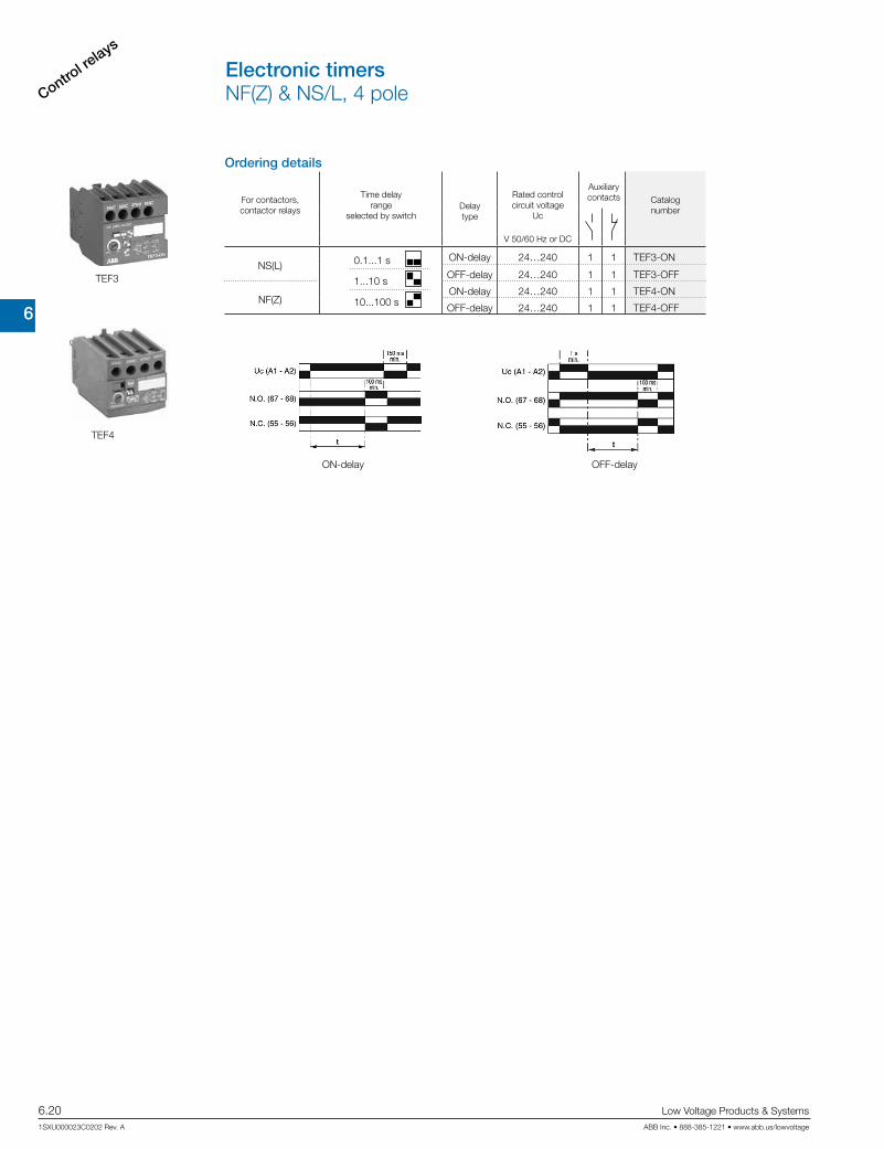
TEF4
TEF3
Ordering details
For contactors,contactor relays
Time delay range
selected by switchDelaytype
Rated control circuit voltage
Uc
Auxiliary contacts Catalog
number
V 50/60 Hz or DC
NS(L)ON-delay 24…240 1 1 TEF3-ON
OFF-delay 24…240 1 1 TEF3-OFF
NF(Z)ON-delay 24…240 1 1 TEF4-ON
OFF-delay 24…240 1 1 TEF4-OFF
Electronic timersNF(Z) & NS/L, 4 pole
0.1...1 s
1...10 s
10...100 s
ON-delay OFF-delay

6
Control relays
Low Voltage Products & Systems 6.21ABB Inc. • 888-385-1221 • www.abb.us/lowvoltage 1SXU000023C0202 Rev. A
Ordering details
For control relaysCatalognumber
Additional coil terminal blockAdditional coil terminal block for a bottom access to the coil terminals of contactors or contactor relays.
NF LDC4
Protective coversSealable and transparent protective covers BX4 and non-removable BX4-CA to protect the devices against accidental contact.
All 1-stack contactors and contactor relays BX4For 4-pole CA4 and 2-pole CAT4 auxiliary contact blocks BX4-CA
For control relays K/C6 LT6-B
Function markersBox of 16 blank cards (16 markers by card) printable on HTP500 thermal transfer printer and AMS 500 marking table to identify your contactors, overload relays or manual motor starters. Marker dimensions: 7 x 20 mm (.276" x .787").
Box of 16 blank cards BA4AMS 500 support plate for 8 BA4 XUSP02633
HTP500 support plate 1SNA235712R2400
BX4
LDC4
BA4
Function markers, protective covers & coil terminal blocksNF(Z), NS/L & K/C6
LT6-B

6
Control re
lays
6.22 Low Voltage Products & Systems
1SXU000023C0202 Rev. A ABB Inc. • 888-385-1221 • www.abb.us/lowvoltage
Standard devices without addition of auxiliary contacts
43
NO
31
NC
21
NC
13
NO
A1 A2
A1 A2
443222
NONCNCNO
14
43
NO
44
33
NO
34
21
NC
22
13
NO
NONONCNO
14
A1 A2
A1 A2
43
NO
44
33
NO
34
23
NO
24
13
NO
NONONONO
14
A1 A2
A1 A2
43
NO
44
33
NO
34
23
NO
24
13
NO81
NC
71
NC
61
NC
51
NC
NONONONO
14
82726252
A1 A2
A1 A2
43NO
NO44
31NC
NC32
21NC
NC22
13NO
NO14
A1
A2
33NO
NO34
21NC
NC22
13NO
NO14
43NO
NO44
A1
A2
NF(Z)22E NF(Z)31E
43NO
NO44
33NO
NO34
23NO
NO24
13NO
NO14
A1
A2
43NO
NO44
33NO
NO34
23NO
NO24
13NO
NO14
81NC
NC82
71NC
NC72
61NC
NC62
51NC
NC52
A1
A2
NF(Z)22E NF(Z)31E NF(Z)40E NF(Z)44E NF(Z)40E NF(Z)44E
43
NO
44
33
NO
34
23
NO
24
13
NO81
NC
71
NC
61
NC
53
NO
NONONONO
14
82726254
A1 A2
A1 A2
43
NO
44
33
NO
34
23
NO
24
13
NO83
NO
71
NC
61
NC
53
NO
NONONONO
14
84726254
A1 A2
A1 A2
43
NO
44
33
NO
34
23
NO
24
13
NO83
NO
73
NO
61
NC
53
NO
NONONONO
14
84746254
A1 A2
A1 A2
43
NO
44
33
NO
34
23
NO
24
13
NO83
NO
73
NO
63
NO
53
NO
NONONONO
14
84746454
A1 A2
A1 A2
43NO
NO44
33NO
NO34
23NO
NO24
13NO
NO14
81NC
NC82
71NC
NC72
61NC
NC62
53NO
NO54
A1
A2
43NO
NO44
33NO
NO34
23NO
NO24
13NO
NO14
83NO
NO84
71NC
NC72
61NC
NC62
53NO
NO54
A1
A2
NF(Z)53E NF(Z)62E
43NO
NO44
33NO
NO34
23NO
NO24
13NO
NO14
83NO
NO84
73NO
NO74
61NC
NC62
53NO
NO54
A1
A2
43NO
NO44
33NO
NO34
23NO
NO24
13NO
NO14
83NO
NO84
73NO
NO74
63NO
NO64
53NO
NO54
A1
A2
NF(Z)53E NF(Z)62E NF(Z)71E NF(Z)80E NF(Z)71E NF(Z)80E
Other possible contact combinations with auxiliary contacts
= +
-3
NO
-4
43
NONONCNO
44
33
34
21
22
13
53
NO
NONONCNO
14
54
A1 A2
A1 A2
A1 A2
5-
5-
43
NONONCNO
332113
443422
NONONCNO
14
A1 A2
+
-1
NC
-2
= +
-1
NC
-2
43
NONONONO
44
33
34
23
24
13
51
NC
NONONONO
14
52
A1 A2
61
NC
62
A1 A2
A1 A2
5-
5-
6-
6-
43
NONONONO
332313
443424
NONONONO
14
A1 A2 33NO
NO34
21NC
NC22
13NO
NO14
43NO
NO44
53NO
NO54
A1
A2
Combination 41 E
43NO
NO44
33NO
NO34
23NO
NO24
13NO
NO14
A1
A2
61NC
NC62
51NC
NC52
Combination 41 = NF(Z)31E + CA4-10 Combination 42 = NF(Z)40E + CA4-01 + CA4-01 Combination 42 E
= +
21X
NC
NC
22X
13X
NO
NO
14X
13X
NO21X
NC
NO
14X
NC
22X
43
NO
44
33
NO
34
23
NO
24
13
NO
NONONONO
14
A1 A2
A1 A2
43
NO
44
33
NO
34
23
NO
24
13
NO
NONONONO
14
A1 A2
A1 A2
= +
83
NO
71
NC
61
NC
53
NO
84726254
43
NO
44
33
NO
34
23
NO
24
13
NO83
NO
71
NC
61
NC
53
NO
NONONONO
14
84726254
A1 A2
A1 A2
43
NO
44
33
NO
34
23
NO
24
13
NO
NONONONO
14
A1 A2
A1 A2 43NO
NO44
33NO
NO34
23NO
NO24
13NO
NO14
A1
A2
21XNC
NC22X
13XNO
NO14X
Combination 51 E
43NO
NO44
33NO
NO34
23NO
NO24
13NO
NO14
53NO
NO54
71NC
NC72
83NO
NO84
61NC
NC62
A1
A2
Combination 51 = CAL4-11 + NF(Z)40E Combination 62 = NF(Z)40E + CA4-22N Combination 62 E
Note: Only NF(Z)Z contactor relays with DC control voltage 12...20 V DC need to respect the connection polarities indicated close to the coil terminals: A1+ for the positive pole and A2- for the negative pole.
Terminal marking & positioningNF(Z), 4 & 8 poleControl relays

6
Control relays
Low Voltage Products & Systems 6.23ABB Inc. • 888-385-1221 • www.abb.us/lowvoltage 1SXU000023C0202 Rev. A
1-pole auxiliary contacts
-1
NC
-2
-3
NO
-4
-5
NC
-6
-7
NO
-8
CA4-01 CA4-10 CC4-01 CC4-10
2-pole auxiliary contacts
13X /
NO
14X /
21X /
NC
22X /
44X
43X 31X
32X
NC NO
31X /
22X
32X /
21X
43X /
14X
44X /
13X
CAL4-11 (Left side-mounted)
CAL4-11(Right side-mounted)
4-pole auxiliary contacts61
62
53
54
81
82
71
72
NO NCNC NC
53
54
63
64
73
74
83
84
NO NONO NO
51
52
63
64
73
74
83
84
NONO NONC
61
62
53
54
83
84
71
72
NO NCNC NO
61
62
51
52
81
82
71
72
NCNC NCNC
CA4-13N CA4-40N CA4-31N CA4-22N CA4-04N
Terminal marking & positioningCA4, CC4, CAL4 & CAT4Auxiliary contacts

6
Control re
lays
6.24 Low Voltage Products & Systems
1SXU000023C0202 Rev. A ABB Inc. • 888-385-1221 • www.abb.us/lowvoltage
A1+
A2-
13 23 33 43
53 61 71 81NO
14 24 34
NO
NO
NO
NO
NO
NO
NO
NCNCNCNO
44
54 62 72 82
A1+
A2-
13 23 33 43
53 61 71 83NO
14 24 34
NO
NO
NO
NO
NO
NO
NO
NONCNCNO
44
54 62 72 84
A1+
A2-
13 23 33 43
53 61 73 83NO
14 24 34
NO
NO
NO
NO
NO
NO
NO
NONONCNO
44
54 62 74 84
A1+
A2-
13 23 33 43
53 63 73 83NO
14 24 34
NO
NO
NO
NO
NO
NO
NO
NONONONO
44
54 64 74 84
43NO
NO44
33NO
NO34
23NO
NO24
13NO
NO14
81NC
NC82
71NC
NC72
61NC
NC62
53NO
NO54
A1+
A2-
43NO
NO44
33NO
NO34
23NO
NO24
13NO
NO14
83NO
NO84
71NC
NC72
61NC
NC62
53NO
NO54
A1+
A2-
43NO
NO44
33NO
NO34
23NO
NO24
13NO
NO14
83NO
NO84
73NO
NO74
63NO
NO64
53NO
NO54
A1+
A2-
43NO
NO44
33NO
NO34
23NO
NO24
13NO
NO14
83NO
NO84
73NO
NO74
61NC
NC62
53NO
NO54
A1+
A2-
A1+
A2-
13 21 31 43
NO
14 22 32
NO
NC
NC
NC
NC
NO
NO
44
A1+
A2-
13 21 33 43
NO
14 22 34
NO
NO
NO
NC
NC
NO
NO
44
A1+
A2-
13 23 33 43
NO
14 24 34
NO
NO
NO
NO
NO
NO
NO
44
A1+
A2-
13 23 33 43
51 61 71 81NO
14 24 34
NO
NO
NO
NO
NO
NO
NO
NCNCNCNC
44
52 62 72 82
33NO
NO34
21NC
NC22
13NO
NO14
43NO
NO44
A1+
A2-
A1+
A2-
13 21 33 43
NO
14 22 34
NO
44
A1+
A2-
13 21 33 43
NO
14 22 34
NO
NO
NO
NC
NC
NO
NO
NO
NO
NC
NC
NO
NO
44
= +-3
-4
NO
5-
5-
53
54
NO
A1+
A2-
13 23 33 43
NO
14 24 34
NO
44
A1+
A2-
13 23 33 43
NO
14 24 34
NO
NO
NO
NO
NO
NO
NO
NO
NO
NO
NO
NO
NO
44
= +-3
-4
NO
5-
5-
53
54
NO
A1+
A2-
13 23 33 43
14 24 34 44
A1+
A2-
13 23 33 43
NO
14 24 34
NO
NO
NO
NO
NO
NO
NO
NO
NO
NO
NO
NO
NO
NO
NO
44
= + +-3
-4
NO
-3
-4
NO
5-
5-
6-
6-
53
54
NO
63
64
NO
43NO
NO44
33NO
NO34
23NO
NO24
13NO
NO14
53NO
NO54
A1+
A2-
43NO
NO44
33NO
NO34
23NO
NO24
13NO
NO14
63NO
NO64
53NO
NO54
A1+
A2-
A1+
A2-
13 23 33 43
14 24 34 44
A1+
A2-
13 23 33 43
NO
14 24 34
NO
NO
NO
NO
NO
NO
NO
NO
NO
NO
NO
NO
NO
NO
NO
44
= + +-1
-2
NC
-1
-2
NC
5-
5-
6-
6-
51
52
NC
61
62
NC
33NO
NO34
21NC
NC22
13NO
NO14
43NO
NO44
53NO
NO54
A1+
A2-
43NO
NO44
33NO
NO34
23NO
NO24
13NO
NO14
A1+
A2-
61NC
NC62
51NC
NC52
43NO
NO44
33NO
NO34
23NO
NO24
13NO
NO14
81NC
NC82
71NC
NC72
61NC
NC62
51NC
NC52
A1+
A2-
43NO
NO44
31NC
NC32
21NC
NC22
13NO
NO14
A1+
A2-
43NO
NO44
33NO
NO34
23NO
NO24
13NO
NO14
A1+
A2-
-3
NO
-4
-3
-4
NO
-1
NC
-2
-1
-2
NC
CA3-10/S CA3-01S
Combination 50E Combination 60E= =NS/L40E/S + CA3-10/S NS/L40E/S + CA3-10/S + CA3-10/S
Combination 42E = NS/L40E/S + CA3-10/S + CA3-01/SCombination 41E = NS/L31E/S + CA3-10/S
1-pole auxiliary contact blocks
NS/L53E/S NS/L62E/S NS/L71E/S NS/L80E/S NS/L80E/SNS/L71E/S
NS/L22E/S NS/L44E/SNS/L31E/S NS/L40E/S NS/L44E/S NS/L40E/S
NS/L53E/S NS/L62E/S
NS/L31E/SNS/L22E/S
Combination 50E
Combination 41E
Combination 60E
Combination 42E
Standard devices without addition of auxiliary contact blocks
Other possible contact combinations with auxiliary contact blocks added by the user
Terminal marking & positioningNS/L 4 & 8 pole & CA3Control relays & auxiliary contacts
NOTE: For DC operated devices, polarity A1+, A2- must be respected.
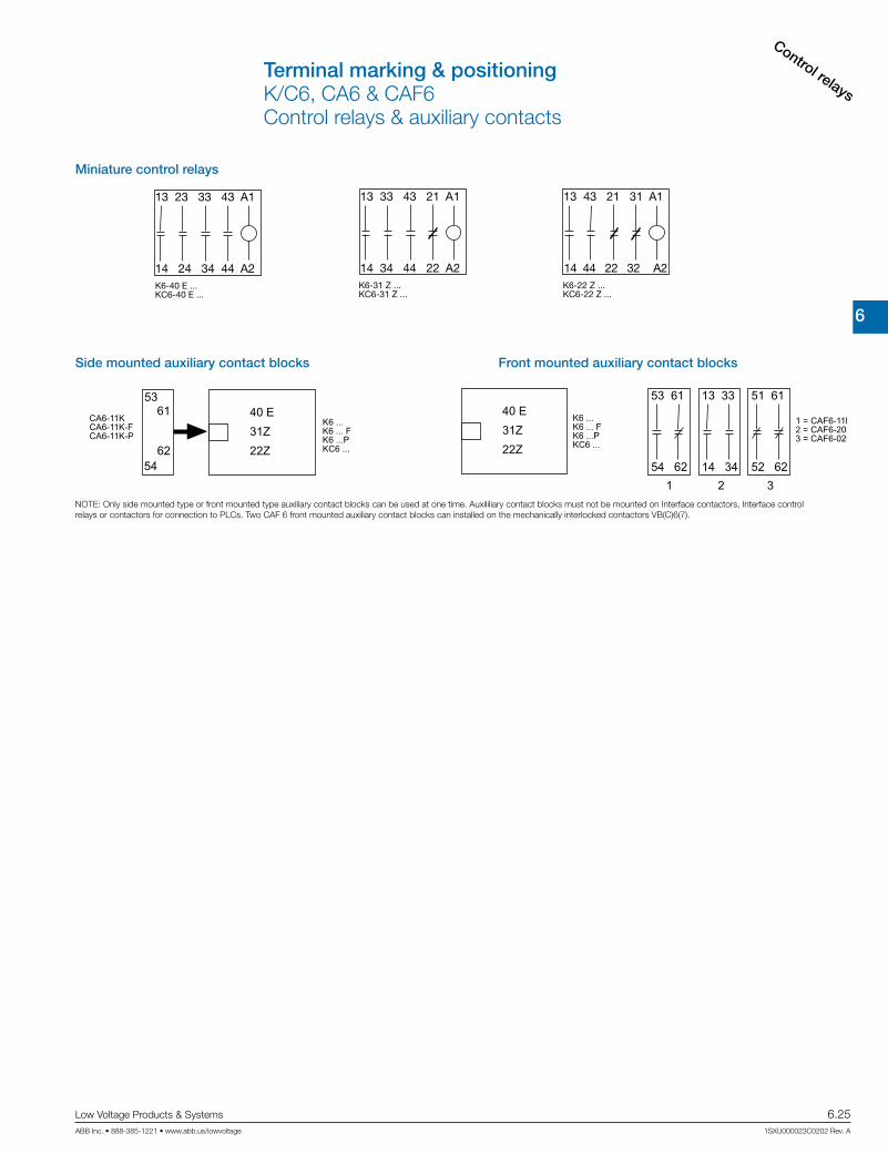
6
Control relays
Low Voltage Products & Systems 6.25ABB Inc. • 888-385-1221 • www.abb.us/lowvoltage 1SXU000023C0202 Rev. A
Terminal marking & positioningK/C6, CA6 & CAF6Control relays & auxiliary contacts
Miniature control relays
1 3 5 13 A1
2 4 6 14 A2
A1 13 1 3 5
A2 14 2 4 6
1 3 5 13 A1
2 4 6 14 A2
1 3 5 21 A1
2 4 6 22 A2
B6(7)-40-00 ...BC6(7)-40-00 ...
B6(7)-30-10 ...BC6(7)-30-10 ...
B6(7)-30-01 ...BC6(7)-30-01 ...
VB6(7)-30-10 ...VBC6(7)-30-10 ...
VB6(7)-30-01 ...VBC6(7)-30-01 ...
K6-40 E ...KC6-40 E ...
K6-31 Z ...KC6-31 Z ...
K6-22 Z ...KC6-22 Z ...
Miniature control relays
Miniature mechanically interlocked contactors
Miniature contactors
A1 21 1 3 5
A2 22 2 4 6
1 3 5 7 A1
2 4 6 8 A2
1 3 5 21 A1
2 4 6 22 A2
13 23 33 43 A1
14 24 34 44 A2
13 33 43 21 A1
14 34 44 22 A2
13 43 21 31 A1
14 44 22 32 A2
Side mounted auxiliary contact blocks Front mounted auxiliary contact blocks
1 2 3
1 3 5 7
2 4 6 8
CA6-11ECA6-11E-FCA6-11E-P
Side mounted auxiliary contact blocks
1321
2214
B6(7)-40-00B6(7)-40-00-FB6(7)-40-00-PBC6(7)-40-00
1 3 5 13
2 4 6 14
CA6-11MCA6-11M-FCA6-11M-P
3321
2234
B6(7)-30-10B6(7)-30-10-FB6(7)-30-10-PBC6(7)-30-10
1 3 5 21
2 4 6 22
CA6-11NCA6-11N-FCA6-11N-P
1331
3214
B6(7)-30-01B6(7)-30-01-FB6(7)-30-01-PBC6(7)-30-01
40 E
31Z
22Z
CA6-11KCA6-11K-FCA6-11K-P
5361
6254
K6 ...K6 ... FK6 ...PKC6 ...
Front mounted auxiliary contact blocks
1 3 5 7
2 4 6 8
1 3 5 13
2 4 6 14
1 3 5 21
2 4 6 22
40 E
31Z
22Z
CAF6 ...
CAF6 ...
CAF6 ...
33 21
34 22
23 33
24 34
21 31
22 32
13 31
14 32
13 33
14 34
11 31
12 32
53 61
54 62
13 33
14 34
51 61
52 62
1 = CAF6-11E2 = CAF6-20E3 = CAF6-02E
1 = CAF6-11M2 = CAF6-20M3 = CAF6-02M
1 = CAF6-11N2 = CAF6-20N3 = CAF6-02N
1 = CAF6-11K2 = CAF6-20K3 = CAF6-02K
B6(7)-40-00B6(7)-40-00-FB6(7)-40-00-PBC6(7)-40-00
B6(7)-30-10B6(7)-30-10-FB6(7)-30-10-PBC6(7)-30-10
B6(7)-30-01B6(7)-30-01-FB6(7)-30-01-PBC6(7)-30-01
K6 ...K6 ... FK6 ...PKC6 ...
13 21
14 22
13 23
14 24
11 21
12 22
NOTE: Only side mounted type or front mounted type auxiliary contact blocks can be used at one time. Auxililiary contact blocks must not be mounted on Interface contactors, Interface controlrelays or contactors for connection to PLCs. Two CAF 6 front mounted auxiliary contact blocks can installed on the mechanically interlocked contactors VB(C)6(7).
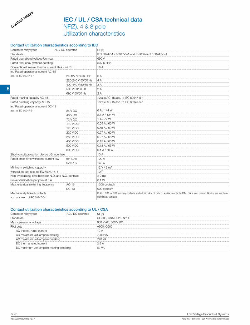
6
Control re
lays
6.26 Low Voltage Products & Systems
1SXU000023C0202 Rev. A ABB Inc. • 888-385-1221 • www.abb.us/lowvoltage
Contact utilization characteristics according to IECContactor relay types AC / DC operated NF(Z)
Standards IEC 60947-1 / 60947-5-1 and EN 60947-1 / 60947-5-1
Rated operational voltage Ue max. 690 V
Rated frequency (without derating) 50 / 60 Hz
Conventional free-air thermal current Ith θ ≤ 40 °C 16 A
Ie / Rated operational current AC-15acc. to IEC 60947-5-1 24-127 V 50/60 Hz 6 A
220-240 V 50/60 Hz 4 A
400-440 V 50/60 Hz 3 A
500 V 50/60 Hz 2 A
690 V 50/60 Hz 2 A
Rated making capacity AC-15 10 x Ie AC-15 acc. to IEC 60947-5-1
Rated breaking capacity AC-15 10 x Ie AC-15 acc. to IEC 60947-5-1
Ie / Rated operational current DC-13acc. to IEC 60947-5-1 24 V DC 6 A / 144 W
48 V DC 2.8 A / 134 W
72 V DC 1 A / 72 W
110 V DC 0.55 A / 60 W
125 V DC 0.55 A / 69 W
220 V DC 0.27 A / 60 W
250 V DC 0.27 A / 68 W
400 V DC 0.15 A / 60 W
500 V DC 0.13 A / 65 W
600 V DC 0.1 A / 60 W
Short-circuit protection device gG type fuse 10 A
Rated short-time withstand current Icw for 1.0 s 100 A
for 0.1 s 140 A
Minimum switching capacity 12 V / 3 mA
with failure rate acc. to IEC 60947-5-4 10-7
Non-overlapping time between N.O. and N.C. contacts ≥ 2 ms
Power dissipation per pole at 6 A 0.1 W
Max. electrical switching frequency AC-15 1200 cycles/h
DC-13 900 cycles/h
Mechanically linked contacts Built-in N.O. or N.C. auxiliary contacts and additional N.O. or N.C. auxiliary contacts (CA4, CAL4 aux. contact blocks) are mechani-cally linked contacts.acc. to annex L of IEC 60947-5-1
Contact utilization characteristics according to UL / CSAContactor relay types AC / DC operated NF(Z)Standards UL 508, CSA C22.2 N°14Max. operational voltage 600 V AC, 600 V DCPilot duty A600, Q600
AC thermal rated current 10 AAC maximum volt-ampere making 7200 VAAC maximum volt-ampere breaking 720 VADC thermal rated current 2.5 ADC maximum volt-ampere making-breaking 69 VA
IEC / UL / CSA technical dataNF(Z), 4 & 8 poleUtilization characteristics

6
Control relays
Low Voltage Products & Systems 6.27ABB Inc. • 888-385-1221 • www.abb.us/lowvoltage 1SXU000023C0202 Rev. A
General technical dataContactor types AC / DC operated NF(Z)Rated insulation voltage Ui
acc. to IEC 60947-5-1 690 V
acc. to UL / CSA 600 VRated impulse withstand voltage Uimp. 6 kVElectromagnetic compatibility Devices complying with IEC 60947-1 / EN 60947-1 - Environment AAmbient air temperature close to contactor
Operation in free air -40...+70 °CStorage -60...+80 °C
Climatic withstand Category B according to IEC 60947-1 Annex QMaximum operating altitude (without derating) 3000 mMechanical durability
Number of operating cycles 20 millions operating cyclesMax. switching frequency 6000 cycles/h
Shock withstandacc. to IEC 60068-2-27 and EN 60068-2-27
Mounting position 1
B2A A B1
C2
C1 Shock direction 1/2 sinusoidal shock for 11 ms: no change in contact position, closed or open positionA 30 gB1 25 g closed position / 5 g open positionB2 15 gC1 25 gC2 25 g
Vibration withstand 5...300 Hzacc. to IEC 60068-2-6 4 g closed position / 2 g open position
Magnet system characteristicsContactor relay types AC / DC operated NF(Z)
Coil operating limits AC supply At θ ≤ 60 °C 0.85 x Uc min...1.1 x Uc max.acc. to IEC 60947-5-1 At θ ≤ 70 °C 0.85 x Uc min...Uc max.
DC supply At θ ≤ 60 °C 0.85 x Uc min...1.1 x Uc max.
At θ ≤ 70 °C (AF) 0.85 x Uc min...Uc max. - (NFZ) 0.85 x Uc min...1.1 x Uc max.
AC control voltage Rated control circuit voltage Uc 24...500 V AC
50/60 Hz Coil consumption Average pull-in value (NF) 50 VA - (NFZ) 16 VA
Average holding value (NF) 2.2 VA / 2 W - (NFZ) 1.7 VA / 1.5 W
DC control voltage Rated control circuit voltage Uc 12...500 V DC
Coil consumption Average pull-in value (NF) 50 W - (NFZ) 12...16 W
Average holding value (NF) 2 W - (NFZ) 1.7 W
PLC-output control (NFZ) ≥ 500 mA 24 V DC
Drop-out voltage ≤ 60 % of Uc min.
Voltage sag immunity acc. to SEMI F47-0706 (NFZ) conditions of use on request
Dips withstand
-20 °C ≤ θ ≤ +60 °C (NFZ) 22 ms average
Operating time
Between coil energization and: N.O. contact closing 40...95 ms
N.C. contact opening 38...90 ms
Between coil de-energization and: N.O. contact opening 11...95 ms
N.C. contact closing 13...98 ms
Mounting characteristicsContactor types AC / DC operated NF(Z)
Mounting positions
Pos. 5
Pos. 3
Pos. 2
Pos. 1 Pos. 1 ± 30°
+30° -30°
Pos. 4
Max. add-on N.C. auxiliary contacts:see accessory fitting details for a NF contactor relay
Mounting distances The contactor relays can be assembled side by side.
Fixing On rail according to IEC 60715, EN 60715 35 x 7.5 mm or 35 x 15 mm
By screws (not supplied) 2 x M4 screws placed diagonally
General technical dataNF(Z) 4 & 8 poleCoil, mounting & operating characteristics

6
Control re
lays
6.28 Low Voltage Products & Systems
1SXU000023C0202 Rev. A ABB Inc. • 888-385-1221 • www.abb.us/lowvoltage
Connecting characteristicsContactor types AC / DC operated NF(Z)
Main terminals
Screw terminals with cable clampConnection capacity (min. ... max.)
Pole and coil terminalsRigid 1 x 1...2.5 mm²
2 x 1...2.5 mm²Flexible with non insulated ferrule 1 x 0.75...2.5 mm²
2 x 0.75...2.5 mm²Flexible with insulated ferrule 1 x 0.75...2.5 mm²
2 x 0.75...1.5 mm²
L6
Lugs L < 8 mm
Connection capacity acc. to UL/CSA 1 or 2 x AWG 18...14Stripping length 10 mmTightening torque
Pole terminals 1.2 Nm / 11 lb.inCoil terminals 1.2 Nm / 11 lb.in
Degree of protectionacc. to IEC 60947-1 / EN 60947-1 and IEC 60529 / EN 60529
All terminals IP20Screw terminals Delivered in open position, screws of unused terminals must be tightened
All terminals M3.5Screwdriver type Flat Ø 5.5 / Pozidriv 2
General technical dataNF(Z), 4 & 8 poleTerminal characteristics

6
Control relays
Low Voltage Products & Systems 6.29ABB Inc. • 888-385-1221 • www.abb.us/lowvoltage 1SXU000023C0202 Rev. A
Contact utilization characteristics according to IECContactor relay types AC operated NS
DC operated NSL
Standards IEC 60947-5-1 and EN 60947-5-1
Rated operational voltage Ue max. 690 V
Rated frequency (without derating) 50 / 60 Hz
Conventional free-air thermal current Ith - θ ≤ 40 °C 10 AIe / Rated operational current AC-15acc. to IEC 60947-5-1 24-127 V 50/60 Hz 6 A
220-240 V 50/60 Hz 4 A
400-440 V 50/60 Hz 3 A
500 V 50/60 Hz 2 A
690 V 50/60 Hz 2 A
Making capacity AC-15 10 x Ie AC-15 acc. to IEC 60947-5-1
Breaking capacity AC-15 10 x Ie AC-15 acc. to IEC 60947-5-1
Ie / Rated operational current DC-13acc. to IEC 60947-5-1 24 V DC 6 A / 144 W
48 V DC 2.8 A / 134 W
72 V DC 1 A / 72 W
110 V DC 0.55 A / 60 W
125 V DC 0.55 A / 69 W
220 V DC 0.27 A / 60 W
250 V DC 0.27 A / 68 W
Short-circuit protection device for contactorsUe ≤ 500 V AC - gG type fuse 10 A
Rated short-time withstand current Icw for 1.0 s 100 A
for 0.1 s 140 A
Minimum switching capacity 12 V / 3 mA
with failure rate acc. to IEC 60947-5-4 10-7
Non-overlapping time between N.O. and N.C. contacts 1.5 msPower dissipation per pole at 6 A 0.1 W
Max. electrical switching frequency AC-15 1200 cycles/h
DC-13 900 cycles/h
Mechanically linked contacts Built-in N.O. or N.C. auxiliary contacts and additional N.O. or N.C. auxiliary contacts (CA3 aux. contact blocks) are mechanically linked contacts.acc. to annex L of IEC 60947-5-1
Contact utilization characteristics according to UL / CSAContactor relay types AC operated NS
DC operated NSL
Standards UL 508, CSA C22.2 N°14
Max. operational voltage 600 V AC, 250 V DC
Pilot duty A600, Q300AC thermal rated current 10 AAC maximum volt-ampere making 7200 VAAC maximum volt-ampere breaking 720 VA
DC thermal rated current 2.5 A
DC maximum volt-ampere making-breaking 69 VA
IEC / UL / CSA technical dataNS/L, 4 & 8 pole, screw terminatedUtilization characteristics

6
Control re
lays
6.30 Low Voltage Products & Systems
1SXU000023C0202 Rev. A ABB Inc. • 888-385-1221 • www.abb.us/lowvoltage
Magnet system characteristics for NS contactor relaysContactor relay types AC operated NS
Coil operating limits AC supplyacc. to IEC 60947-5-1 0.85...1.1 x Uc (at θ ≤ 60 °C); Uc (at θ ≤ 70 °C)
AC control voltage Rated control circuit voltage Uc at 50 Hz 24...415 V
at 60 Hz 24...415 V
Coil consumption Average pull-in value 50 Hz 33 VA
60 Hz 33 VA
50/60 Hz 33 VA
Average holding value 50 Hz 6.5 VA / 1.5 W
60 Hz 5 VA / 1.2 W
50/60 Hz 6.5 VA / 1.5 W
Drop-out voltage Approx. 30...50 % of Uc
Operating time
Between coil energization and: N.O. contact closing 9...24 ms
N.C. contact opening 6...18 ms
Between coil de-energization and: N.O. contact opening (1) 5...19 ms
N.C. contact closing (1) 7...22 ms
(1) The use of RC5-1 surge suppressor increases opening time by a factor of 2 to 3.
Magnet system characteristics for NSL contactor relaysContactor relay types DC operated NSL
Coil operating limits DC supplyacc. to IEC 60947-5-1 0.85...1.1 x Uc (at θ ≤ 60 °C); Uc (at θ ≤ 70 °C)DC control voltage Rated control circuit voltage Uc 12...240 V DC
Coil consumption Average pull-in value 3 W
Average holding value 3 W
Drop-out voltage Approx. 10...40 % of Uc
Coil time constant Open L/R 12 ms
Closed L/R 40 ms
Operating time
Between coil energization and: N.O. contact closing 36...59 ms
N.C. contact opening 31...53 ms
Between coil de-energization and: N.O. contact opening (1) 13...17 ms
N.C. contact closing (1) 15...20 ms
(1) The use of RT5 surge suppressor increases opening time by a factor of 1.1 to 1.2.
Mounting characteristics and conditions for useContactor relay types AC operated NS
DC operated NSL
Mounting positions
Pos. 3
Pos. 2
Pos. 1
Pos. 4
Pos. 5
Mounting distances The contactor relays can be assembled side by side.
Fixing On rail according to IEC 60715, EN 60715 35 x 7.5 mm or 35 x 15 mm
By screws (not supplied) 2 x M4 screws placed diagonally
General technical data NS/L, 4 & 8 pole, screw terminatedCoil & mounting characteristics

6
Control relays
Low Voltage Products & Systems 6.31ABB Inc. • 888-385-1221 • www.abb.us/lowvoltage 1SXU000023C0202 Rev. A
General technical dataContactor relay types AC operated NS
DC operated NSLRated insulation voltage Ui
acc. to IEC 60947-5-1 690 V
acc. to UL / CSA 600 V
Rated impulse withstand voltage Uimp. 6 kV
Ambient air temperature close to contactor relay
Operation in free air -40...+70 °C
Storage -60...+80 °C
Climatic withstand Category B according to IEC 60947-1 Annex Q
Maximum operating altitude (without derating) 3000 m
Mechanical durability
Number of operating cycles 20 millions operating cycles
Max. switching frequency 3600 cycles/h
Shock withstand 1/2 sinusoidal shock for 11 ms: no change in contact position, closed or open positionacc. to IEC 60068-2-27 and EN 60068-2-27 Shock direction NS contactor relays - AC operated NSL contactor relays - DC operatedMounting position 1 A 20 g 20 g closed position / 10 g open position
B1 5 g 15 g closed position / 5 g open position
B2 15 g 10 g
C1 19 g closed position / 8 g open position 19 g closed position / 8 g open position
C2 16 g closed position / 13 g open position 14 g closed position / 8 g open position
Vibration withstand acc. to IEC 60068-2-6 5...300 Hz / 3 g closed position / 2 g open position
Connecting characteristicsContactor relay types AC operated NS
DC operated NSL
Main terminals
Screw terminals with cable clamp
Connection capacity (min. ... max.)Pole and coil terminals
Rigid solid 1 x 0.75...2.5 mm²2 x 0.75...2.5 mm²
Flexible with non insulated ferrule 1 x 0.75...2.5 mm²2 x 0.75...2.5 mm²
Flexible with insulated ferrule 1 x 0.75...2.5 mm²2 x 0.75...1.5 mm²
LlLugs L ≤ 7.7 mm
l > 3.2 mmConnection capacity acc. to UL / CSA 1 or 2 x AWG 18...14Stripping length 9 mmTightening torque Recommended 1.00 Nm / 9 lb.in
Max. 1.20 NmDegree of protection acc. to IEC 60947-1 / EN 60947-1 and IEC 60529 / EN 60529
All terminals IP20Screw terminals Delivered in open position, screws of unused terminals must be tightened
All terminals M3Screwdriver type Flat Ø 5.5 / Pozidriv 2
B2A A B1
C2
C1
General technical dataNS/L, 4 & 8 pole, screw terminatedOperating & terminal characteristics
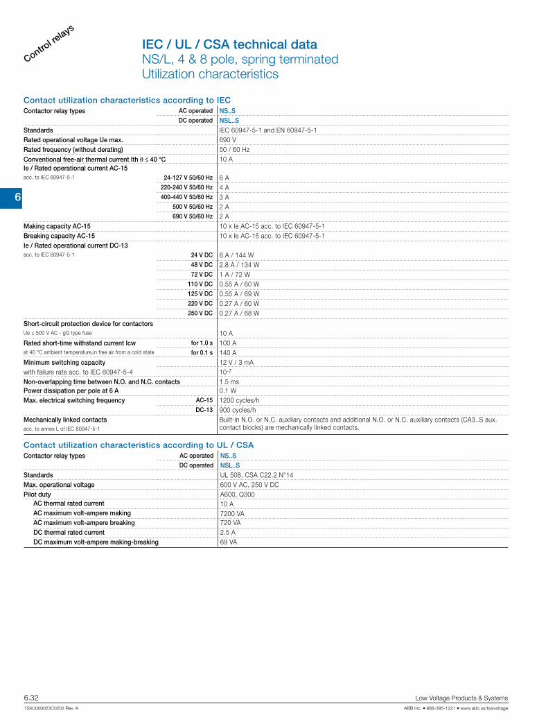
6
Control re
lays
6.32 Low Voltage Products & Systems
1SXU000023C0202 Rev. A ABB Inc. • 888-385-1221 • www.abb.us/lowvoltage
IEC / UL / CSA technical data NS/L, 4 & 8 pole, spring terminatedUtilization characteristics
Contact utilization characteristics according to IECContactor relay types AC operated NS..S
DC operated NSL..SStandards IEC 60947-5-1 and EN 60947-5-1Rated operational voltage Ue max. 690 VRated frequency (without derating) 50 / 60 HzConventional free-air thermal current Ith θ ≤ 40 °C 10 AIe / Rated operational current AC-15acc. to IEC 60947-5-1 24-127 V 50/60 Hz 6 A
220-240 V 50/60 Hz 4 A400-440 V 50/60 Hz 3 A
500 V 50/60 Hz 2 A690 V 50/60 Hz 2 A
Making capacity AC-15 10 x Ie AC-15 acc. to IEC 60947-5-1Breaking capacity AC-15 10 x Ie AC-15 acc. to IEC 60947-5-1Ie / Rated operational current DC-13acc. to IEC 60947-5-1 24 V DC 6 A / 144 W
48 V DC 2.8 A / 134 W72 V DC 1 A / 72 W
110 V DC 0.55 A / 60 W125 V DC 0.55 A / 69 W220 V DC 0.27 A / 60 W250 V DC 0.27 A / 68 W
Short-circuit protection device for contactorsUe ≤ 500 V AC - gG type fuse 10 ARated short-time withstand current Icw for 1.0 s 100 Aat 40 °C ambient temperature,in free air from a cold state for 0.1 s 140 AMinimum switching capacity 12 V / 3 mAwith failure rate acc. to IEC 60947-5-4 10-7
Non-overlapping time between N.O. and N.C. contacts 1.5 msPower dissipation per pole at 6 A 0.1 WMax. electrical switching frequency AC-15 1200 cycles/h
DC-13 900 cycles/hMechanically linked contacts Built-in N.O. or N.C. auxiliary contacts and additional N.O. or N.C. auxiliary contacts (CA3..S aux.
contact blocks) are mechanically linked contacts.acc. to annex L of IEC 60947-5-1
Contact utilization characteristics according to UL / CSAContactor relay types AC operated NS..S
DC operated NSL..SStandards UL 508, CSA C22.2 N°14Max. operational voltage 600 V AC, 250 V DCPilot duty A600, Q300
AC thermal rated current 10 AAC maximum volt-ampere making 7200 VAAC maximum volt-ampere breaking 720 VADC thermal rated current 2.5 ADC maximum volt-ampere making-breaking 69 VA

6
Control relays
Low Voltage Products & Systems 6.33ABB Inc. • 888-385-1221 • www.abb.us/lowvoltage 1SXU000023C0202 Rev. A
Magnet system characteristics for NS..S contactor relaysContactor relay types AC operated NS..SCoil operating limits AC supplyacc. to IEC 60947-5-1 0.85...1.1 x Uc (at θ ≤ 60 °C); Uc (at θ ≤ 70 °C)AC control voltage Rated control circuit voltage Uc at 50 Hz 24...415 V
at 60 Hz 24...415 VCoil consumption Average pull-in value 50 Hz 33 VA
60 Hz 33 VA50/60 Hz 33 VA
Average holding value 50 Hz 6.5 VA / 1.5 W60 Hz 5 VA / 1.2 W
50/60 Hz 6.5 VA / 1.5 WDrop-out voltage Approx. 30...50 % of UcOperating time
Between coil energization and: N.O. contact closing 9...24 msN.C. contact opening 6...18 ms
Between coil de-energization and: N.O. contact opening (1) 5...19 msN.C. contact closing (1) 7...22 ms
(1) The use of RC5-1 surge suppressor increases opening time by a factor of 2 to 3.
Magnet system characteristics for NSL..S contactor relaysContactor relay types DC operated NSL..SCoil operating limits DC supplyacc. to IEC 60947-5-1 0.85...1.1 x Uc (at θ ≤ 60 °C); Uc (at θ ≤ 70 °C)DC control voltage
Rated control circuit voltage Uc 12...240 V DCCoil consumption Average pull-in value 3 W
Average holding value 3 WDrop-out voltage Approx. 10...40 % of UcCoil time constant Open L/R 12 ms
Closed L/R 40 msOperating time
Between coil energization and: N.O. contact closing 36...59 msN.C. contact opening 31...53 ms
Between coil de-energization and: N.O. contact opening (1) 13...17 msN.C. contact closing (1) 15...20 ms
(1) The use of RT5 surge suppressor increases opening time by a factor of 1.1 to 1.2.
Mounting characteristics and conditions for useContactor relay types AC operated NS..S
DC operated NSL..SMounting positions
Pos. 3
Pos. 2
Pos. 1
Pos. 4
Pos. 5
Mounting distances The contactor relays can be assembled side by side.Fixing On rail according to IEC 60715, EN 60715 35 x 7.5 mm or 35 x 15 mm
By screws (not supplied) 2 x M4 screws placed diagonally
General technical dataNS/L, 4 & 8 pole, spring terminatedCoil & mounting characteristics

6
Control re
lays
6.34 Low Voltage Products & Systems
1SXU000023C0202 Rev. A ABB Inc. • 888-385-1221 • www.abb.us/lowvoltage
General technical dataContactor relay types AC operated NS..S
DC operated NSL..SRated insulation voltage Ui
acc. to IEC 60947-5-1 690 Vacc. to UL / CSA 600 V
Rated impulse withstand voltage Uimp. 6 kVAmbient air temperature close to contactor relay
Operation in free air -40...+70 °CStorage -60...+80 °C
Climatic withstand Category B according to IEC 60947-1 Annex QMaximum operating altitude (without derating) 3000 mMechanical durability
Number of operating cycles 20 millions operating cyclesMax. switching frequency 3600 cycles/h
Shock withstand 1/2 sinusoidal shock for 11 ms: no change in contact position, closed or open positionacc. to IEC 60068-2-27 and EN 60068-2-27 Shock directionMounting position 1
B2A A B1
C2
C1
NS contactor relays - AC operated NSL contactor relays - DC operatedA 20 g 20 g closed position / 10 g open position
B1 5 g 15 g closed position / 5 g open positionB2 15 g 10 gC1 19 g closed position / 8 g open position 19 g closed position / 8 g open positionC2 16 g closed position / 13 g open position 14 g closed position / 8 g open position
Vibration withstand 5...300 Hz3 g closed position / 2 g open positionacc. to IEC 60068-2-6
Connecting characteristicsContactor relay types AC operated NS..S
DC operated NSL..SMain terminals
Spring terminals
Connection capacity (min. ... max.)Pole and coil terminals
Rigid solid 1 x 0.75...2.5 mm²2 x 0.75...2.5 mm²
Flexible with non insulated ferrule 1 x 0.75...2.5 mm²2 x 0.75...2.5 mm²
Flexible with insulated ferrule 1 x 0.75...1.5 mm²2 x 0.75...1.5 mm²
Connection capacity acc. to UL / CSA 1 or 2 x AWG 18...14Stripping length 10 mm
Degree of protection acc. to IEC 60947-1 / EN 60947-1 and IEC 60529 / EN 60529
All terminals IP20Screwdriver type Flat Ø 3.5
General technical dataNS/L, 4 & 8 pole, spring terminatedOperating & terminal characteristics
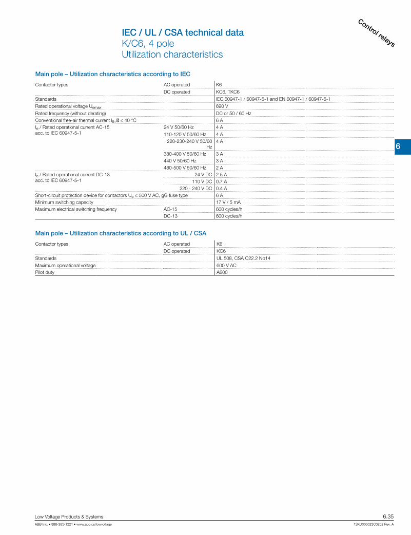
6
Control relays
Low Voltage Products & Systems 6.35ABB Inc. • 888-385-1221 • www.abb.us/lowvoltage 1SXU000023C0202 Rev. A
Main pole – Utilization characteristics according to IEC
Contactor types AC operated K6
DC operated KC6, TKC6
Standards IEC 60947-1 / 60947-5-1 and EN 60947-1 / 60947-5-1
Rated operational voltage Uemax 690 V
Rated frequency (without derating) DC or 50 / 60 HzConventional free-air thermal current lth θ ≤ 40 °C 6 AIe / Rated operational current AC-15acc. to IEC 60947-5-1
24 V 50/60 Hz 4 A
110-120 V 50/60 Hz 4 A220-230-240 V 50/60
Hz4 A
380-400 V 50/60 Hz 3 A440 V 50/60 Hz 3 A480-500 V 50/60 Hz 2 A
Ie / Rated operational current DC-13acc. to IEC 60947-5-1
24 V DC 2.5 A110 V DC 0.7 A
220 - 240 V DC 0.4 AShort-circuit protection device for contactors Ue ≤ 500 V AC, gG fuse type 6 AMinimum switching capacity 17 V / 5 mAMaximum electrical switching frequency AC-15 600 cycles/h
DC-13 600 cycles/h
Main pole – Utilization characteristics according to UL / CSA
Contactor types AC operated K6
DC operated KC6
Standards UL 508, CSA C22.2 No14
Maximum operational voltage 600 V ACPilot duty A600
IEC / UL / CSA technical dataK/C6, 4 poleUtilization characteristics

6
Control re
lays
6.36 Low Voltage Products & Systems
1SXU000023C0202 Rev. A ABB Inc. • 888-385-1221 • www.abb.us/lowvoltage
General technical dataK/C6, 4 poleCoil & operating characteristics
General technical data
Contactor relay types AC operated K6
DC operated KC6
Rated insulation voltage Ui
acc. to IEC 60947-5-1 690 Vacc. to UL/CSA 600 V
Rated impulse withstand voltage Uimp 6 kVElectromagnetic compatibilityAmbient air temperature close to contactor relay Operation in free air -25 ... +55 °C
Storage -40 ... +80 °CClimatic withstand acc. to IEC 60068-2-30Maximum operating altitude (without derating) 2000 mMechanical durability 107 operating cyclesResistance to shock Half-sine
acc. IEC 60068-2-27 and EN 60068-2-27 15 g / 11msacc. to IEC/EN 60947-1 Annex. Q Category E
Resistance to vibrations Sinusoidalacc. IEC 60068-2-27 and EN 60068-2-27 5 g / 3 ... 150 Hzacc. to IEC/EN 60947-1 Annex. Q Kategorie E
Magnet system characteristics for K6 contactor relays
Contactor relay types AC operated K6Coil operating limits acc. to IEC 60947-4-1 AC supply 0.85 ... 1.1 x UC
AC control voltageCoil consumption Average pull-in value 3.5 VA / 3.5 W
Average holding value 3.5 VA / 3.5 WDrop-out voltage in % of UC min. Approx. 20 ... 75%
Magnet system characteristics for KC6, TKC6 contactor relays
Contactor relay types DC operated KC6 TKC6Coil operating limits acc. to IEC 60947-5-1 DC supply 0.85 ... 1.1 x UC See ordering detailsDC control voltage
Coil consumption Average pull-in value 3.5 VA / 3.5 W 5 VA / 5 WAverage holding value 3.5 VA / 3.5 W 5 VA / 5 W
Drop-out voltage in % of UC min. 10 ... 75 % 10 ... 75 %
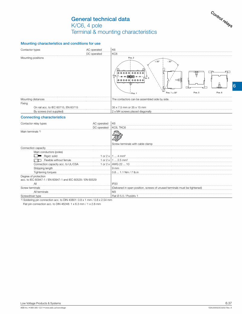
6
Control relays
Low Voltage Products & Systems 6.37ABB Inc. • 888-385-1221 • www.abb.us/lowvoltage 1SXU000023C0202 Rev. A
General technical data K/C6, 4 poleTerminal & mounting characteristics
Mounting characteristics and conditions for use
Contactor types AC operated K6DC operated KC6
Mounting positions
Pos. 1
Pos. 2
Pos. 4
Pos. 1 ± 30°
- 30°+ 30°
Pos. 5 Pos. 6
Pos. 3
Mounting distances The contactors can be assembled side by side.Fixing
On rail acc. to IEC 60715, EN 60715 35 x 7.5 mm or 35 x 15 mmBy screws (not supplied) 2 x M4 screws placed diagonally
Connecting characteristics
Contactor relay types AC operated K6DC operated KC6, TKC6
Main terminals 1)
Screw terminals with cable clampConnection capacity
Main conductors (poles) Rigid: solid 1 or 2 x 1 ... 4 mm²
Flexible without ferrule 1 or 2 x 1 ... 2.5 mm²Connection capacity acc. to UL/CSA 1 or 2 x AWG 22 ... 10Stripping length 9 mmTightening torques 0.8 ... 1.1 Nm / 7 lb.in
Degree of protection acc. to IEC 60947-1 / EN 60947-1 and IEC 60529 / EN 60529
All IP20Screw terminals (Delivered in open position, screws of unused terminals must be tightened)
All terminals M3Screwdriver type Flat Ø 5.5 / Pozidriv 11) Soldering pin connection acc. to DIN 40801: 0.8 x 1 mm / 0.8 x 2.54 mm Flat pin connection acc. to DIN 46248: 1 x 6.3 mm / 1 x 2.8 mm

6
Control re
lays
6.38 Low Voltage Products & Systems
1SXU000023C0202 Rev. A ABB Inc. • 888-385-1221 • www.abb.us/lowvoltage
Notes
6
TimersCT Range
Low Voltage Products & Systems 6.39ABB Inc. • 888-385-1221 • www.abb.us/lowvoltage 1SXU000023C0202 Rev. A
Electronic timers
Elec
troni
c tim
ers
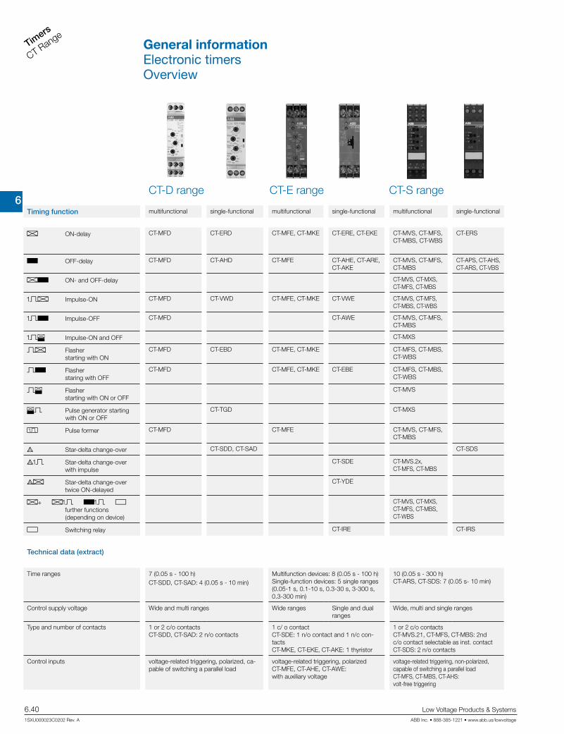
6
Timers
CT Range
6.40 Low Voltage Products & Systems
1SXU000023C0202 Rev. A ABB Inc. • 888-385-1221 • www.abb.us/lowvoltage
CT-S rangeCT-E rangeCT-D range
Timing function multifunctional single-functional multifunctional single-functional multifunctional single-functional
A ON-delay CT-MFD CT-ERD CT-MFE, CT-MKE CT-ERE, CT-EKE CT-MVS, CT-MFS, CT-MBS, CT-WBS
CT-ERS
B OFF-delay CT-MFD CT-AHD CT-MFE CT-AHE, CT-ARE, CT-AKE
CT-MVS, CT-MFS, CT-MBS
CT-APS, CT-AHS, CT-ARS, CT-VBS
AB ON- and OFF-delay CT-MVS, CT-MXS, CT-MFS, CT-MBS
CA Impulse-ON CT-MFD CT-VWD CT-MFE, CT-MKE CT-VWE CT-MVS, CT-MFS, CT-MBS, CT-WBS
CB Impulse-OFF CT-MFD CT-AWE CT-MVS, CT-MFS, CT-MBS
CE Impulse-ON and OFF CT-MXS
A Flasher starting with ON
CT-MFD CT-EBD CT-MFE, CT-MKE CT-MFS, CT-MBS, CT-WBS
B Flasher staring with OFF
CT-MFD CT-MFE, CT-MKE CT-EBE CT-MFS, CT-MBS, CT-WBS
E Flasher starting with ON or OFF
CT-MVS
E Pulse generator starting with ON or OFF
CT-TGD CT-MXS
H Pulse former CT-MFD CT-MFE CT-MVS, CT-MFS, CT-MBS
F Star-delta change-over CT-SDD, CT-SAD CT-SDS
FC Star-delta change-over with impulse
CT-SDE CT-MVS.2x, CT-MFS, CT-MBS
FA Star-delta change-over twice ON-delayed
CT-YDE
A+ AC BC G further functions (depending on device)
CT-MVS, CT-MXS, CT-MFS, CT-MBS, CT-WBS
G Switching relay CT-IRE CT-IRS
Technical data (extract)
Time ranges 7 (0.05 s - 100 h)CT-SDD, CT-SAD: 4 (0.05 s - 10 min)
Multifunction devices: 8 (0.05 s - 100 h) Single-function devices: 5 single ranges (0.05-1 s, 0.1-10 s, 0.3-30 s, 3-300 s, 0.3-300 min)
10 (0.05 s - 300 h) CT-ARS, CT-SDS: 7 (0.05 s- 10 min)
Control supply voltage Wide and multi ranges Wide ranges Single and dual ranges
Wide, multi and single ranges
Type and number of contacts 1 or 2 c/o contacts CT-SDD, CT-SAD: 2 n/o contacts
1 c/ o contact CT-SDE: 1 n/o contact and 1 n/c con-tacts CT-MKE, CT-EKE, CT-AKE: 1 thyristor
1 or 2 c/o contacts CT-MVS.21, CT-MFS, CT-MBS: 2nd c/o contact selectable as inst. contact CT-SDS: 2 n/o contacts
Control inputs voltage-related triggering, polarized, ca-pable of switching a parallel load
voltage-related triggering, polarized CT-MFE, CT-AHE, CT-AWE: with auxiliary voltage
voltage-related triggering, non-polarized, capable of switching a parallel load CT-MFS, CT-MBS, CT-AHS: volt-free triggering
General informationElectronic timersOverview

6
TimersCT Range
Low Voltage Products & Systems 6.41ABB Inc. • 888-385-1221 • www.abb.us/lowvoltage 1SXU000023C0202 Rev. A
J existing j pending
CT-D
Approvals CT-
MFD
.12
CT-
MFD
.21
CT-
ER
D.1
2
CT-
ER
D.2
2
CT-
AH
D.1
2
CT-
AH
D.2
2
CT-
VW
D.1
2
CT-
EB
D.1
2
CT-
TGD
.12
CT-
TGD
.22
CT-
SD
D.2
2
CT-
SA
D.2
2
A UL 508, CAN/CSA C22.2 No.14 J J J J J J J J J J J J
D GOST J J J J J J J J J J J J
K CB scheme J J J J J J J J J J J J
E CCC J J J J J J J J J J J J
Marks
a CE J J J J J J J J J J J J
b C-Tick J j J j J j J J J j j j
J existing j pending
CT-E
Approvals CT-
MFE
CT-
ER
E
CT-
AH
E
CT-
AR
E
CT-
VW
E
CT-
AW
E
CT-
EB
E
CT-
YD
E
CT-
SD
E
CT-
IRE
CT-
MK
E
CT-
EK
E
CT-
AK
E
A UL 508, CAN/CSA C22.2 No.14 J J J J J J J J J J J J J
C GL J J J J J J J J J J J J J
D GOST J J J J J J J J J J J J J
K CB scheme J J J J J J J J J J
E CCC J J J J J J J J J J
L RMRS J J J J J J J J J J J J J
Marks
a CE J J J J J J J J J J J J J
b C-Tick J J J J J J J J J J J J J
J existing j pending
CT-S
Approvals CT-
MV
S.1
2
CT-
MV
S.2
x
CT-
MXS
.22
CT-
MFS
.21
CT-
MB
S.2
2
CT-
WB
S.2
2
CT-
ER
S.1
2
CT-
ER
S.2
x
CT-
AP
S.1
2
CT-
AP
S.2
x
CT-
AH
S.2
2
CT-
AR
S.1
1
CT-
AR
S.2
1
CT-
VB
S.1
x
CT-
SD
S.2
x
CT-
IRS
.1x
CT-
IRS
.2x
CT-
IRS
.3x
A UL 508, CAN/CSA C22.2 No.14 J J J J J J J J J J J J J J J
C GL J J J J J J J J J J J j j J
D GOST J J J J J J J J J J J J J J J J J J
K CB scheme J J J J J J J J J J J J J J J J J J
E CCC J J J J J J J J J J J J J J J J J J
Marks
a CE J J J J J J J J J J J J J J J J J J
b C-Tick J J J J J J J J J J J J J J J J J J
General informationElectronic timersApprovals and marks

6
Timers
CT Range
6.42 Low Voltage Products & Systems
1SXU000023C0202 Rev. A ABB Inc. • 888-385-1221 • www.abb.us/lowvoltage
Notes
6
TimersCT Range
Low Voltage Products & Systems 6.43ABB Inc. • 888-385-1221 • www.abb.us/lowvoltage 1SXU000023C0202 Rev. A
CT-D Range
Elec
troni
c tim
ers
CT-
D R
ange

6
Timers
CT Range
6.44 Low Voltage Products & Systems
1SXU000023C0202 Rev. A ABB Inc. • 888-385-1221 • www.abb.us/lowvoltage
CT-D RangeBenefits and advantages
Operating controls1 LEDs for status indication
U - green LED:
V control supply voltage applied
W timing
R, R1, R2 - yellow LED:
V output relay energized
2 Time range adjustment
3 Fine adjustment of the time delay
4 Timing range selector
multi-functional single-functional
LEDs for status indicationAll actual operational states are displayed by front-face LEDs, thus simplifying com-missioning and troubleshooting.
Connection terminalsWide terminal spacing allows connection of wires: 2 x 1.5 mm² (2 x 16 AWG) with wire end ferrules or - 2 x 2.5 mm² (2 x 14 AWG) without ferrules.
Direct reading scalesDirect setting of the time delay without any additional calculation provides accurate time delay adjustment.
Width 17,5 mmWith their width of 17.5 mm only, the CT-D range timers are ideally suited for installa-tion in distribution panels.
Switching currentsThe CT-D range timers allow an output load of up to 6 A on devices with 1 c/o contact and up to 5 A on devices with 2 c/o contacts.
Characteristics• Diversity: – 2 multifunction timers – 10 single-function timers• Control supply voltages: – Wide range: 12-240 V AC/DC – Multi range: 24-48 V DC, 24-240 V AC• 7 time ranges from 0.05s to 100 h or 4 time ranges from 0.05 s - 10 min• Width of only 17.5 mm• Light-grey housing in RAL 7035• Devices with:
– 1 c/o contact (250 V / 6 A) or 2 c/o contacts (250 V / 5 A) – Control input: voltage-related triggering, polarized, capable of switching a parallel load
• Approvals / Marks (partly depending)
A, D, K, E / a, b
Benefits
4
2
3
1
2
3
1
1
2
2
3
3
4
4

6
TimersCT Range
Low Voltage Products & Systems 6.45ABB Inc. • 888-385-1221 • www.abb.us/lowvoltage 1SXU000023C0202 Rev. A
Synonyms
used expression alternative expression(s) used expression alternative expression(s)
1 c/o contact SPDT voltage-related wet / non-floating
2 c/o contacts DPDT volt-free dry / floating
Description
The CT-D range with a width of only 17.5 mm fits into all domestic installation and distribution panels.For maximum flexibility in operation, 10 single-function as well as 2 multifunction devices with 7 timing functions are available. The devices offer 4 or 7 time ranges from 0.05 seconds up to 100 hours. Their wide input range allows the use in applications worldwide.
Ordering details
Time function
Rated control supply
voltage
Time ranges
Control input
OutputReference
codeCatalog number
Weight(1 pce)
kg (lb)
A B
CA CB A B
H
24-240 V AC 24-48 V DC
7 (0.05 s - 100 h) 1 c/o CT-MFD.12 1SVR500020R0000 0.060 (0.132)
A B
CA CB A B
H
12-240 V AC/DC
7 (0.05 s - 100 h) 2 c/o CT-MFD.21 1SVR500020R11000.065 (0.143)
A
24-240 V AC 24-48 V DC
7 (0.05 s - 100 h)
1 c/o CT-ERD.12 1SVR500100R0000 0.060 (0.132)
A 2 c/o CT-ERD.22 1SVR500100R01000.065 (0.143)
B 1 c/o CT-AHD.12 1SVR500110R0000 0.060 (0.132)
B 2 c/o CT-AHD.22 1SVR500110R01000.065 (0.143)
CA 1 c/o CT-VWD.12 1SVR500130R00000.060 (0.132)
A 1 c/o CT-EBD.12 1SVR500150R0000
E2 x 7 (0.05 s -
100 h)
1 c/o CT-TGD.121) 1SVR500160R0000 0.060 (0.132)
E 1 c/o CT-TGD.221) 1SVR500160R01000.065 (0.143)
F4 (0.05 s - 10 min)
2 n/o CT-SDD.222) 1SVR500211R0100 0.065 (0.143)F 2 n/o CT-SAD.223) 1SVR500210R0100
CT-MFD.12
CT-ERD.22
A ON-delay B OFF-delay CA Impulse-ON CB Impulse-OFF A Flasher starting with ON B Flasher staring with OFFH Pulse former E Pulse generator F Star-delta change-over
1) ON and OFF times adjustable independently: 2 x 7 time ranges 0.05 s - 100 h2) Transition time 50 ms fixed3) Transition time adjustable
CT-D RangeOrdering details
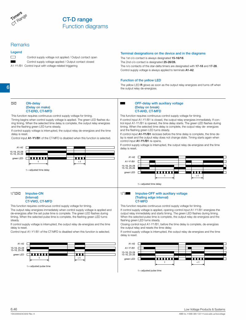
6
Timers
CT Range
6.46 Low Voltage Products & Systems
1SXU000023C0202 Rev. A ABB Inc. • 888-385-1221 • www.abb.us/lowvoltage
CT-D rangeFunction diagrams
RemarksLegend
G Control supply voltage not applied / Output contact open
B Control supply voltage applied / Output contact closed A1-Y1/B1 Control input with voltage-related triggering
Terminal designations on the device and in the diagramsThe 1st c/o contact is always designated 15-16/18.The 2nd c/o contact is designated 25-26/28.The n/o contacts of the star-delta timers are designated with 17-18 and 17-28. Control supply voltage is always applied to terminals A1-A2.
Function of the yellow LEDThe yellow LED R glows as soon as the output relay energizes and turns off when the output relay de-energizes.
A ON-delay (Delay on make) CT-ERD, CT-MFD
B OFF-delay with auxiliary voltage (Delay on break) CT-AHD, CT-MFD
This function requires continuous control supply voltage for timing. Timing begins when control supply voltage is applied. The green LED flashes du-ring timing. When the selected time delay is complete, the output relay energizes and the flashing green LED turns steady. If control supply voltage is interrupted, the output relay de-energizes and the time delay is reset.Control input A1-Y1/B1 of the CT-MFD is disabled when this function is selected.
This function requires continuous control supply voltage for timing. If control input A1-Y1/B1 is closed, the output relay energizes immediately. If con-trol input A1-Y1/B1 is opened, the time delay starts. The green LED flashes during timing. When the selected time delay is complete, the output relay de- energizes and the flashing green LED turns steady. If control input A1-Y1/B1 recloses before the time delay is complete, the time de-lay is reset and the output relay does not change state. Timing starts again when control input A1-Y1/B1 re-opens.If control supply voltage is interrupted, the output relay de-energizes and the time delay is reset.A1-A2
15-16, 25-2615-18, 25-28
t < tgreen LED
t = adjusted time delay
A1-A2
15-16, 25-2615-18, 25-28
t
A1-Y1/B1
< tgreen LED
t = adjusted time delay
CA Impulse-ON (Interval) CT-VWD, CT-MFD
CB Impulse-OFF with auxiliary voltage (Trailing edge interval) CT-MFD
This function requires continuous control supply voltage for timing. The output relay energizes immediately when control supply voltage is applied and de-energizes after the set pulse time is complete. The green LED flashes during timing. When the selected pulse time is complete, the flashing green LED turns steady. If control supply voltage is interrupted, the output relay de-energizes and the time delay is reset.Control input A1-Y1/B1 of the CT-MFD is disabled when this function is selected.
This function requires continuous control supply voltage for timing. If control supply voltage is applied, opening control input A1-Y1/B1 energizes the output relay immediately and starts timing. The green LED flashes during timing. When the selected pulse time is complete, the output relay de-energizes and the flashing green LED turns steady. Closing control input A1-Y1/B1, before the time delay is complete, de-energizes the output relay and resets the time delay.If control supply voltage is interrupted, the output relay de-energizes and the time delay is reset.
A1-A2
15-16, 25-2615-18, 25-28
t < tgreen LED
t = adjusted pulse time
A1-A2
15-16, 25-2615-18, 25-28
t
A1-Y1/B1
< tgreen LED
t = adjusted pulse time

6
TimersCT Range
Low Voltage Products & Systems 6.47ABB Inc. • 888-385-1221 • www.abb.us/lowvoltage 1SXU000023C0202 Rev. A
CT-D rangeFunction diagrams
A Flasher, starting with the ON time (Recycling equal times, ON first) CT-EBD, CT-MFD
B Flasher, starting with the OFF time (Recycling equal times, OFF first) CT-MFD
Applying control supply voltage starts timing with symmetrical ON & OFF times. The cycle starts with an ON time first. The ON & OFF times are displayed by the flashing green LED, which flashes twice as fast during the OFF time. If control supply voltage is interrupted, the output relay de-energizes and the time delay is reset.Control input A1-Y1/B1 of the CT-MFD is disabled when this function is selected.
Applying control supply voltage starts timing with symmetrical ON & OFF times. The cycle starts with an OFF time first. The ON & OFF times are displayed by the flashing green LED, which flashes twice as fast during the OFF time. If control supply voltage is interrupted, the output relay de-energizes and the time delay is reset.Control input A1-Y1/B1 of the CT-MFD is disabled when this function is selected.
A1-A2
15-16, 25-2615-18, 25-28
t tgreen LED
t = adjusted ashing time
A1-A2
15-16, 25-2615-18, 25-28
t tgreen LED
t = adjusted ashing time
H Pulse former (Single shot) CT-MFD
E Pulse generator, starting with the ON or OFF time (Recycling unequal times, ON or OFF first) CT-TGDThis function requires continuous control supply voltage for timing.
Closing control input A1-Y1/B1 energizes the output relay immediately and starts timing. Operating the control contact switch A1-Y1/B1 during the time delay has no effect. The green LED flashes during timing. When the selected ON time is complete, the output relay de-energizes and the flashing green LED turns steady. After the ON time is complete, it can be restarted by closing control input A1-Y1/B1. If control supply voltage is interrupted, the output relay de-energizes and the time delay is reset.
This function requires continuous control supply voltage for timing. Applying control supply voltage, with open control input A1-Y1/B1, starts timing with an ON time first. Applying control supply voltage, with closed control input A1-Y1/B1, starts timing with an OFF time first. The ON & OFF times are displayed by the flashing green LED, which flashes twice as fast during the OFF time. The ON & OFF times are independently adjustable. If control supply voltage is interrupted, the output relay de-energizes and the time delay is reset.
A1-A2
15-16, 25-2615-18, 25-28
t t
A1-Y1/B1
green LED
t = adjusted pulse time
A1-A2
A1-Y1/B1
15-16, 25-2615-18, 25-28
t1 t1t2 t2
green LED
t1 = adjusted OFF timet2 = adjusted ON time
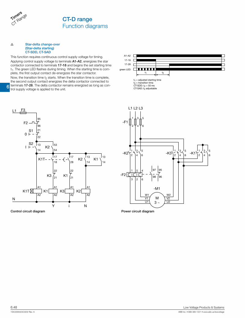
6
Timers
CT Range
6.48 Low Voltage Products & Systems
1SXU000023C0202 Rev. A ABB Inc. • 888-385-1221 • www.abb.us/lowvoltage
CT-D rangeFunction diagrams
K1T
K1T
K3
K3
Y i N
K2
K2
K2
L1
N
F3
F295
96
21
22
22
21
A1
A2
A1
A2
A1
A2
A1
A2
22
21
13
14
17
18
17
28
13
14
13
14
53
54
S10
IS2
K1
K1
K1
-K1-K3
L1
-F11
2
95
96
97
98
L2
3
4
L3
5
6
1
2
3
4
5
6
1
2
3
4
5
6-K2
-F2
1
2
3
4
5
6
1
3
5
2
4
6
M3 ~
W2V2U2
W1V1U1
-M1
F Star-delta change-over (Star-delta starting) CT-SDD, CT-SADThis function requires continuous control supply voltage for timing. Applying control supply voltage to terminals A1-A2, energizes the star contactor connected to terminals 17-18 and begins the set starting time t1. The green LED flashes during timing. When the starting time is com-plete, the first output contact de-energizes the star contactor. Now, the transition time t2 starts. When the transition time is complete, the second output contact energizes the delta contactor connected to terminals 17-28. The delta contactor remains energized as long as con-trol supply voltage is applied to the unit.
A1-A2
t1 t2
green LED
t1 = adjusted starting timet2 = transition timeCT-SDD: t2 = 50 msCT-SAD: t2 adjustable
17-18
17-28
Power circuit diagramControl circuit diagram

6
TimersCT Range
Low Voltage Products & Systems 6.49ABB Inc. • 888-385-1221 • www.abb.us/lowvoltage 1SXU000023C0202 Rev. A
CT-D rangeConnection diagrams
CT-MFD.21 CT-MFD.12 A CT-ERD.12
B CT-AHD.22
A1
A1
28
28
26
26
A218 16 Y1/B1
A2
15
25
1816
15
25
Y1/B1
A1
A1
28
28
26
26
A218 16 Y1/B1
A2
15
25
1816
15
25
Y1/B1
A1
A1
28
28
26
26
A218 16
A2
15 25
25
1816
15
A CT-ERD.22
B CT-AHD.12 CA CT-VWD.12 A CT-EBD.12
E CT-TGD.22
A1
A1
28
18
26
16
A218 16 Y1/B1
A2
15
15
2826
25
25
Y1/B1
A1
A1
A2 18 28
17
17
28 18 A2
E CT-TGD.12 F CT-SDD.22 F CT-SAD.22
A1
A1
18
18
16
16
A2
A2
15
15
Y1/B1
Y1/B1
A1
A1
18
18
16
16
A2
A2
15
15
A1
A1
18
18
16
16
A2
A2
15
15
Y1/B1
Y1/B1
A1
A1
18
18
16
16
A2
A2
15
15
A1
A1
18
18
16
16
A2
A2
15
15
A1
A1
18
18
16
16
A2
A2
15
15
Y1/B1
Y1/B1
A1
A1
A2 18 28
17
17
28 18 A2
A1-A2 Supply: 12-240 V AC/DC
15-16/18 1. c/o contact25-26/28 2. c/o contactA1-Y1/B1 Control input
A1-A2 Supply: 24-48 V DC or 24-240 V AC15-16/18 1. c/o contact
A1-Y1/B1 Control input
A1-A2 Supply: 24-48 V DC or 24-240 V AC15-16/18 1. c/o contact
A1-A2 Supply: 24-48 V DC or 24-240 V AC15-16/18 1. c/o contact25-26/28 2. c/o contactA1-Y1/B1 Control input
A1-A2 Supply: 24-48 V DC or 24-240 V AC15-16/18 1. c/o contact25-26/28 2. c/o contact
A1-A2 Supply: 24-48 V DC or 24-240 V AC15-16/18 1. c/o contactA1-Y1/B1 Control input
A1-A2 Supply: 24-48 V DC or 24-240 V AC15-16/18 1. c/o contact
A1-A2 Supply: 24-48 V DC or 24-240 V AC15-16/18 1. c/o contact
A1-A2 Supply: 24-48 V DC or 24-240 V AC15-16/18 1. c/o contact25-26/28 2. c/o contactA1-Y1/B1 Control input
A1-A2 Supply: 24-48 V DC or 24-240 V AC15-16/18 1. c/o contact
A1-Y1/B1 Control input
A1-A2 Supply: 24-48 V DC or 24-240 V AC17-18 1. n/o contact (star contactor)17-28 2. n/o contact (delta contactor)
A1-A2 Supply: 24-48 V DC or 24-240 V AC17-18 1. n/o contact (star contactor)17-28 2. n/o contact (delta contactor)

6
Timers
CT Range
6.50 Low Voltage Products & Systems
1SXU000023C0202 Rev. A ABB Inc. • 888-385-1221 • www.abb.us/lowvoltage
CT-D rangeTechnical data
Data at Ta = 25 °C and rated values, unless otherwise indicatedCT-D with 1 c/o
contact
CT-D with 2 c/o
contacts
CT-MFD.21
Input circuit - Supply circuit
Rated control supply voltage Us 24-240 V AC / 24-48 V DC 12-240 V AC/DC
Rated control supply voltage US tolerance -15...+10 %
Rated frequencyAC/DC versions DC or 50/60 Hz
AC versions 50/60 HzFrequency range DC or 47-63 HzTypical current / power consumption see data sheetPower failure buffering time min. 20 ms min. 30 msInput circuit - Control circuitKind of triggering voltage-related triggering
Control input, Control function A1-Y1/B1 start timing externalParallel load / polarized yes / yesRated operational voltage Ue 250 VMinimum switching voltage / minimum switching current 12 V / 100 mAMaximum switching voltage / maximum switching current see load limit curvesMinimum control pulse length 30 msControl voltage potential see rated control supply voltageCurrent consumption of the control input max. 4 mA see data sheet
Timing circuit
Time ranges7 time ranges 0.05 s - 100 h
1.) 0.05-1 s 2.) 0.5-10 s 3.) 5-100 s 4.) 0.5-10 min
5.) 5-100 min 6.) 0.5-10 h 7.) 5-100 h
4 time ranges 0.05 s - 10 min (CT-SDD, CT-SAD) 1.) 0.05-1 s 2.) 0.5-10 s 3.) 5-100 s 4.) 0.5-10 min
Recovery time < 50 msAccuracy within the rated control supply voltage tolerance it < 0.005 % / VAccuracy within the temperature range it < 0.06 % / °C
Repeat accuracy (constant parameters) it < ± 0.5 %
Star-delta transition time CT-SDD / CT-SAD fixed 50 ms / adjustable: 20-100 ms in steps of 10 msStar-delta transition time tolerance CT-SDD / CT-SAD ±3 msIndication of operational states
Control supply voltage / timing U: green LEDV: control supply voltage applied
W: timingRelay status R: yellow LED V: output relay energizedOutput circuit
Kind of output15-16/18 Relay, 1 c/o contact -
15-16/18; 25-26/28 - Relay, 2 c/o contacts17-18; 17-28 relay, 2 n/o contacts (CT-SDD, CT-SAD)
Contact material Cd-free, see data sheetRated operational voltage Ue IEC/EN 60947-1 250 VMinimum switching voltage / minimum switching current 12 V / 100 mAMaximum switching voltage / maximum switching current see load limit curves
Rated operational current Ie (IEC/EN 60947-5-1 )
AC12 (resistive) at 230 V 6 A 5 A
AC15 (inductive) at 230 V 3 A 3 A0.75 A
(AC15 n/c contact)AC15 (inductive) at 230 V 6 A 5 ADC13 (inductive) at 24 V 2 A 2 A 1) 1 A
AC rating (UL 508)
Utilization category Rating Code) B 300 C 300
max. rated operational voltage 300 V ACMaximum continuous thermal current
at B300 5 A 2.5 A
max. making/breaking apparent power at B300 3600 VA / 360 VA 1800 VA / 180 VA
Mechanical lifetime 30 x 106 switching cyclesElectrical lifetime 0.1 x 10⁶ switching cyclesMax. fuse rating to achieve short-circuit protection (IEC/EN 60947-5-1)
n/c contact 6 A fast-actingn/o contact 10 A fast-acting

6
TimersCT Range
Low Voltage Products & Systems 6.51ABB Inc. • 888-385-1221 • www.abb.us/lowvoltage 1SXU000023C0202 Rev. A
CT-D rangeTechnical data
CT-D with 1 c/o
contact
CT-D with 2 c/o
contacts
CT-MFD.21
General dataDuty time 100%
Dimensions (W x H x D)17.5 x 70 x 58 mm
(0.69 x 2.76 x 2.28 in)
17.5 x 80 x 58 mm
(0.69 x 3.15 x 2.28 in)
Weight see ordering detailsMounting DIN rail (IEC/EN 60715), snap-mounting without any toolMounting position anyMinimum distance to other units horizontal / vertical no / noDegree of protection housing / terminals IP50 / IP20Electrical connection
Wire size
fine-strand with(out) wire end ferrule2 x 0.5-1.5 mm2 (2 x 20-16 AWG)
1 x 0.5-2.5 mm2 (1 x 20-14 AWG)
rigid2 x 0.5-1.5 mm2 (2 x 20-16 AWG)
1 x 0.5-4 mm2 (1 x 20-12 AWG)Stripping length 7 mm (0,28 in)Tightening torque 0.5-0.8 NmEnvironmental dataAmbient temperature range operation / storage -20 ... +60 °C / -40 ... +85 °CDamp heat (cyclic) IEC/EN 60068-2-30 6 x 24 h cycles, 55 °C, 95 % RHVibration (sinusoidal) IEC/EN 60068-2-6 40 m/s2, 20 cycles, 10....150...10 HzShock (half-sine) IEC/EN 60068-2-27 100 m/s2, 11 msIsolation dataRated impulse withstand voltage Uimp between all isolated circuits VDE 0110, IEC/EN 60664-1 4 kV; 1.2/50 µs
Pollution category IEC/EN 60664-1, VDE 0110 3Overvoltage category IEC/EN 60664-1, VDE 0110 III
Rated insulation voltage Uiinput circuit / output circuit 300 V
output circuit 1 / output circuit 2 300 VBasic insulation (IEC/EN 61140) input circuit / output circuit 300 VProtective separation (VDE 0106 part 101 and part 101/A1; IEC/EN 61140) input circuit / output circuit 250 V
Power-frequency withstand voltage test (test voltage, routine test) between all isolated circuits 2.5 kV, 50 Hz, 1 s
StandardsProduct standard IEC 61812-1, EN 61812-1 + A11, DIN VDE 0435 part 2021Low Voltage Directive 2006/95/ECEMC Directive 2004/108/ECRoHS Directive 2002/95/EC
Electromagnetic compatibilityInterference immunity to IEC/EN 61000-6-1, IEC/EN 61000-6-2
electronic discharge IEC/EN 61000-4-2 Level 3 (6 kV / 8 kV)radiated, radio-frequency. electromagnetic filed IEC/EN 61000-4-3 Level 3 (10 V / m)electrical fast transient/burst IEC/EN 61000-4-4 Level 3 (2 kV / 5 kHz)surge IEC/EN 61000-4-5 Level 4conducted disturbances, induced by radio-frequency fi elds IEC/EN 61000-4-6 Level 3 (10 V)
Interference emissions IEC/EN 61000-6-3, IEC/EN 61000-6-4high-frequency radiated IEC/CISPR 22, EN 55022 Class Bhigh-frequency conducted IEC/CISPR 22, EN 55022 Class

6
Timers
CT Range
6.52 Low Voltage Products & Systems
1SXU000023C0202 Rev. A ABB Inc. • 888-385-1221 • www.abb.us/lowvoltage
CT-D rangeTechnical data, Technical diagrams
CT-D.2x CT-D.2x
Derating factor F for inductive AC load
Contact lifetime
DC current [A]
resistive load
DC
vol
tage
[V]
AC current [A]
resistive load
AC
vol
tage
[V]
Switching current [A]
250 Vresistive load
Sw
itchi
ng c
ycle
s
cos j
0.5
0.1 0.2 0.3 0.4 0.5 0.6 0.7 0.8 0.9 1.0
0.6
0.7
0.8
0.9
1.0
Der
atin
g fa
ctor
F
CT-D.1x CT-D.1x
AC load (resistive) DC load (resistive)
Technical diagrams
Load limit curves
DC current [A]
resistive load
DC
vol
tage
[V]
AC current [A]
resistive load
AC
vol
tage
[V]

6
TimersCT Range
Low Voltage Products & Systems 6.53ABB Inc. • 888-385-1221 • www.abb.us/lowvoltage 1SXU000023C0202 Rev. A
CT-D rangeApproximate dimensions
0.69“
2.76
“
0.2“2.28“
1.71“
1.77
“
17,5
70
5
58
43,4
45
0.69“17,5
3.15
“80
0.2“5
2.28“
1.71“
58
43,4
1.77
“45
CT-D devices with 1 c/o contact or 2 n/o contacts CT-D devices with 2 c/o contacts
Dimensional drawings dimensions in mm
L(+)
N(-)
A1 Y1/B1
A2
Wiring notes for devices with control inputA parallel load to the control input is possible
6
Timers
CT Range
6.54 Low Voltage Products & Systems
1SXU000023C0202 Rev. A ABB Inc. • 888-385-1221 • www.abb.us/lowvoltage
Notes

6
TimersCT Range
Low Voltage Products & Systems 6.55ABB Inc. • 888-385-1221 • www.abb.us/lowvoltage 1SXU000023C0202 Rev. A
CT-E range
Elec
troni
c Ti
mer
sC
T-E
Ran
ge

6
Timers
CT Range
6.56 Low Voltage Products & Systems
1SXU000023C0202 Rev. A ABB Inc. • 888-385-1221 • www.abb.us/lowvoltage
Characteristics• Diversity:
– 2 multifunction timers– 56 single-function timers– 4 switching relays
• Control supply voltages:– Dual range: 24 V AC/DC– Single range: 110-130 V AC, 220-240 V AC– Wide range: 24-240 V AC/DC (CT-MFE)
• Time ranges– 5 single ranges: 0.05-1 s, 0.1-10 s, 0.3-30 s, 3-300 s, 0.3-30 min– 8 time ranges: 0.05 s - 100 h (CT-MFE)
• Devices with 1 c/o (SPDT) contact (250 V / 4 A) or solid-state output for high switching frequencies (thyristor 0.8 A)
• Switching relay CT-IRE for added switching contacts with either side-by-side or diagonally positioned connection terminals
1 LEDs for status indication
U - green LED: V control supply voltage applied
R2: red LED: V output relay energized
2 Time range adjustment (only multifunctional devices)
3 Fine adjustment of the time delay
4 Preselection of the timing function (only multifunctional devices)
Operating controls
LEDs for status indication 2All actual operational states are displayed by front-face LEDs, thus simplifying com-missioning and troubleshooting.
Direct reading scales 1Direct setting of the time delay without any additional calculation provides accurate time delay adjustment.
Connection screws in M3 (Pozidrive 1) 3Easy and fast tightening and release of the connection screws with pozidrive, pan- or crosshead screwdriver.
Solid-state output 4Devices with solid-state output are the perfect solution for high operation cycles.
4
1
2
3
Benefits
ALA1
A1
AL
1 2 3 4
CT-E rangeBenefits and advantages
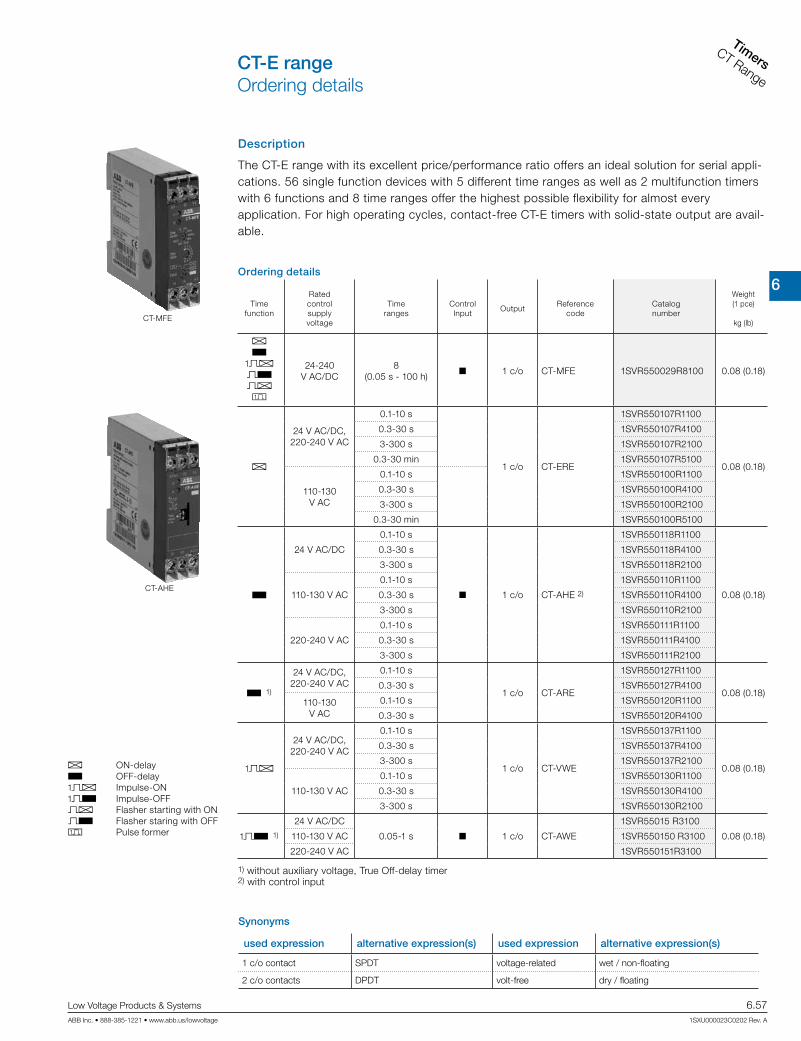
6
TimersCT Range
Low Voltage Products & Systems 6.57ABB Inc. • 888-385-1221 • www.abb.us/lowvoltage 1SXU000023C0202 Rev. A
CT-E rangeOrdering details
CT-MFE
CT-AHE
A ON-delay B OFF-delay CA Impulse-ON CB Impulse-OFF A Flasher starting with ON B Flasher staring with OFF H Pulse former
Description
The CT-E range with its excellent price/performance ratio offers an ideal solution for serial appli-cations. 56 single function devices with 5 different time ranges as well as 2 multifunction timers with 6 functions and 8 time ranges offer the highest possible flexibility for almost everyapplication. For high operating cycles, contact-free CT-E timers with solid-state output are avail-able.
Ordering details
Time function
Rated control supply voltage
Time ranges
Control Input
OutputReference
codeCatalognumber
Weight(1 pce)
kg (lb)
A B
CA B A H
24-240 V AC/DC
8 (0.05 s - 100 h)
1 c/o CT-MFE 1SVR550029R8100 0.08 (0.18)
A
24 V AC/DC,220-240 V AC
0.1-10 s
1 c/o CT-ERE
1SVR550107R1100
0.08 (0.18)
0.3-30 s 1SVR550107R4100
3-300 s 1SVR550107R2100
0.3-30 min 1SVR550107R5100
110-130 V AC
0.1-10 s 1SVR550100R1100
0.3-30 s 1SVR550100R4100
3-300 s 1SVR550100R2100
0.3-30 min 1SVR550100R5100
B
24 V AC/DC
0.1-10 s
1 c/o CT-AHE 2)
1SVR550118R1100
0.08 (0.18)
0.3-30 s 1SVR550118R4100
3-300 s 1SVR550118R2100
110-130 V AC
0.1-10 s 1SVR550110R1100
0.3-30 s 1SVR550110R4100
3-300 s 1SVR550110R2100
220-240 V AC
0.1-10 s 1SVR550111R1100
0.3-30 s 1SVR550111R4100
3-300 s 1SVR550111R2100
B 1)
24 V AC/DC,220-240 V AC
0.1-10 s
1 c/o CT-ARE
1SVR550127R1100
0.08 (0.18)0.3-30 s 1SVR550127R4100
110-130 V AC
0.1-10 s 1SVR550120R1100
0.3-30 s 1SVR550120R4100
CA
24 V AC/DC,220-240 V AC
0.1-10 s
1 c/o CT-VWE
1SVR550137R1100
0.08 (0.18)
0.3-30 s 1SVR550137R4100
3-300 s 1SVR550137R2100
110-130 V AC
0.1-10 s 1SVR550130R1100
0.3-30 s 1SVR550130R4100
3-300 s 1SVR550130R2100
CB 1)
24 V AC/DC
0.05-1 s 1 c/o CT-AWE
1SVR55015 R3100
0.08 (0.18)110-130 V AC 1SVR550150 R3100
220-240 V AC 1SVR550151R3100
1) without auxiliary voltage, True Off-delay timer2) with control input
Synonyms
used expression alternative expression(s) used expression alternative expression(s)
1 c/o contact SPDT voltage-related wet / non-floating
2 c/o contacts DPDT volt-free dry / floating

6
Timers
CT Range
6.58 Low Voltage Products & Systems
1SXU000023C0202 Rev. A ABB Inc. • 888-385-1221 • www.abb.us/lowvoltage
CT-E rangeOrdering details
Ordering details
Time function
Rated control supply voltage
Time ranges
Control Input
OutputReference
codeCatalognumber
Weight(1 pce)
kg (lb)
CB
24 V AC/DC
0.1-10 s
1 c/oCT-AWE 2)
1SVR550148R1100
0.08 (0.18)
0.3-30 s 1SVR550148R4100
3-300 s 1SVR550148R2100
110-130 V AC
0.1-10 s 1SVR550140R1100
0.3-30 s 1SVR550140R4100
3-300 s 1SVR550140R2100
220-240 V AC
0.1-10 s 1SVR550141R1100
0.3-30 s 1SVR550141R4100
3-300 s 1SVR550141R2100
B
24 V AC/DC,220-240 V AC 0.1-10 s 1 c/o
CT-EBE 7)
1SVR550167R1100 0.08 (0.18)
110-130 V AC 1SVR550160R1100
FA
24 V AC/DC,220-240 V AC
0.1-10 s
1 c/oCT-YDE 1)
1SVR550207R1100
0.08 (0.18)
0.3-30 s 1SVR550207R4100
3-300 s 1SVR550207R2100
110-130 V AC
0.1-10 s 1SVR550200R1100
0.3-30 s 1SVR550200R4100
3-300 s 1SVR550200R2100
FC
24 V AC/DC,220-240 V AC
0.3-30 s1 n/o + 1
n/cCT-SDE 3) 8)
1SVR550217R41000.08 (0.18)110-130 V AC 1SVR550210R4100
380-415 V AC 1SVR550212R4100
A CA A B
24-240 V AC/DC
0.1-10 s,3-300 s
solid-state
CT-MKE 6) 9) 1SVR550019R00000.08 (0.18)
A24-240
V AC/DC
0.1-10 s
CT-EKE
1SVR550509R10000.08 (0.18)
0.3-30 s 1SVR550509R4000
3-300 s 1SVR550509R2000
B 24-240 V AC
0.1-10 s
CT-AKE
1SVR550519R10000.08 (0.18)
0.3-30 s 1SVR550519R4000
3-300 s 1SVR550519R2000
G
24 V AC/DC1 c/o
CT-IRE 4)
1SVR550228R91000.08 (0.18)220-240 V AC/
DC1SVR550221R9100
G
24 V AC/DC1 c/o
CT-IRE 5)
1SVR550238R91000.08 (0.18)220-240
V AC/DC1SVR550231R9100
CT-AWE
CT-IRE
A ON-delay B OFF-delay CA Impulse-ON CB Impulse-OFF A Flasher starting with ON B Flasher staring with OFF H Pulse former G Switching relay FA Star-delta change-over twice ON-delayedFC Star-delta change-over with impulseE Pulse generator starting with ON or OFF
1) without auxiliary voltage2) with control input3) with fixed transition time4) A1/A2 diagonally5) A1/A2 on top6) solid-state output, functions and time range selection via external jumpers7) symetric ON & OFF times8) common contact9) Functions: ON-delay (AC/DC), Impuls-ON (AC only), Flasher starting with OFF (AC only)
NoticeCT-...KE are solid-state timers with thyristor output for 2-wire applications. They are connected directly in series with the control coil of contactors or relays. Voltage should not be applied with-out a load connected, because there is no current limiting in the unit.

6
TimersCT Range
Low Voltage Products & Systems 6.59ABB Inc. • 888-385-1221 • www.abb.us/lowvoltage 1SXU000023C0202 Rev. A
CT-E rangeFunction diagrams
A ON-delay (Delay on make) CT-ERE, CT-MFE
B OFF-delay, with auxiliary voltage (Delay on break) CT-AHE, CT-MFE
t = adjusted time delay t = adjusted time delayMinimum control pulse length: 20 ms
< t
A1-A2/B1
15-1815-16
t
green LED
red LED
A1-A2
A1-Y1
15-1615-18
t
green LED
red LED
Timing begins when control supply voltage is applied. When the selected time de-lay is complete, the output relay energizes.If control supply voltage is interrupted, the output relay de-energizes and the time delay is reset.Interrupting control supply voltage before the time delay is complete, resets the time delay. The output relay does not energize.Control input A1-Y1 of the CT-MFE is disabled when this function is selected.
This function requires continuous control supply voltage for timing.Timing is controlled by a control input, connected to terminals A1-Y1. If the control contact is closed, the output relay energizes. If control input A1-Y1 is opened, the selected time delay starts. When the time delay is complete, the output relay de-energizes.If control input A1-Y1 closes before the time delay is complete, the time delay is reset. Timing starts again when the control input re-opens.
RemarksLegend
G Control supply voltage not applied / Output contact open
B Control supply voltage applied / Output contact closed A1-Y1/B1 Control input with voltage-related triggering
Terminal designations on the device and in the diagramsThe c/o contact is always designated 15-16/18.The n/o contacts are designated with 15-16 and 15-18. Control supply voltage is always applied to terminals A1-A2/B1.
Function of the red LEDThe red LED R glows as soon as the output relay energizes and turns off when the output relay de-energizes.

6
Timers
CT Range
6.60 Low Voltage Products & Systems
1SXU000023C0202 Rev. A ABB Inc. • 888-385-1221 • www.abb.us/lowvoltage
CT-E rangeFunction diagrams
CA Impulse-ON (Interval) CT-VWE, CT-MFE
B OFF-delay, without auxiliary voltage (true delay on break) CT-ARE
t = adjusted time delay
A1-A2/B1
15-1815-16
t
green LED
This function requires continuous control supply voltage. Opening control input A1-Y1, energizes the output relay immediately and timing begins. When the selected time delay is complete, the output relay de-energizes. Interrupting control supply voltage or closing control input A1-Y1, before the time delay is complete, de-energizes the output relay and resets the time delay.
The Impulse-OFF function without auxiliary voltage does not require control supply voltage for timing. If control supply voltage is interrupted, the output relay energizes and the OFF time starts. When timing is complete, the output relay de-energizes. If control supply voltage is re-applied, before the time delay is complete, the time delay is reset and the output relay de-energizes. Control supply voltage must be applied for the minimum energizing time (200 ms), for proper operation.
t = adjusted pulse time
A1-A2
A1-Y1
15-1615-18
t
green LED
red LED
t = adjusted pulse time
A1-A2
15-1615-18
t
green LED
red LED
The output relay energizes immediately when control supply voltage is applied and de-energizes when the selected time delay is complete. If control supply voltage is interrupted before the time delay is complete, the output relay de-energizes and the time delay is reset.The control input A1-Y1 of the CT-MFE has to be jumpered if this timing function is configured.
CT-VWE:
CT-MFE:
The OFF-delay function without auxiliary voltage does not require control supply voltage for timing. Applying control supply voltage, energizes the output relay. If control supply volt-age is interrupted, the OFF-delay starts. When timing is complete, the output relay de-energizes. If control supply voltage is re-applied, before the time delay is complete, the time delay is reset and the output relay remains energized. Control supply voltage must be applied for the minimum energizing time (200 ms), for proper operation.
CB Impulse-OFF, with auxiliary voltage (Trailing edge interval) CT-AWE
CB Impulse-OFF, without auxiliary voltage (True trailing edge interval) CT-AWE
t = adjusted pulse time
A1-A2/B1
15-1815-16
< tt
LED grün
LED rot
t = adjusted pulse time
A1-A2
15-1815-16
< tt
A1-Y1
LED grün
LED rot
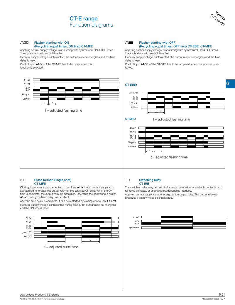
6
TimersCT Range
Low Voltage Products & Systems 6.61ABB Inc. • 888-385-1221 • www.abb.us/lowvoltage 1SXU000023C0202 Rev. A
CT-E rangeFunction diagrams
A Flasher starting with ON (Recycling equal times, ON first) CT-MFE
B Flasher starting with OFF (Recycling equal times, OFF first) CT-EBE, CT-MFE
G Switching relay CT-IRE
H Pulse former (Single shot) CT-MFE
A1-A2
15-1615-18
green LED
t = adjusted pulse time
A1-A2
A1-Y1
15-1615-18
tt
green LED
red LED
The switching relay may be used to increase the number of available contacts or to reinforce contacts, or as a coupling/decoupling interface.Applying control supply voltage, energizes the output relay. The output relay de-energizes if supply voltage is interrupted.
Closing the control input connected to terminals A1-Y1, with control supply volt-age applied, energizes the output relay for the selected ON time. When the ON time is complete, the output relay de-energizes. Operating the control input switch A1-Y1 during the time delay has no effect. After the time delay is complete, it can be restarted by closing control input A1-Y1. If control supply voltage is interrupted during timing, the output relay de-energizes and the ON time is reset.
Applying control supply voltage, starts timing with symmetrical ON & OFF times. The cycle starts with an ON time first. If control supply voltage is interrupted, the output relay de-energizes and the time delay is reset.Control input A1-Y1 of the CT-MFE has to be open when this function is selected.
Applying control supply voltage, starts timing with symmetrical ON & OFF times. The cycle starts with an OFF time first. If control supply voltage is interrupted, the output relay de-energizes and the time delay is reset.Control input A1-Y1 of the CT-MFE has to be jumpered when this function is se-lected.
CT-EBE:
CT-MFE:
t = adjusted flashing time
A1-A2
A1-Y1
15-1615-18
t t
LED grün
LED rot
t = adjusted flashing time
A1-A2/B1
15-1615-18
t t
LED grün
LED rot
15-1615-1815-1615-18
t t
A1-A2
A1-Y1
LED grün
LED rot
t = adjusted flashing time

6
Timers
CT Range
6.62 Low Voltage Products & Systems
1SXU000023C0202 Rev. A ABB Inc. • 888-385-1221 • www.abb.us/lowvoltage
CT-E rangeFunction diagrams
-K1-K3
L1
-F11
2
95
96
97
98
L2
3
4
L3
5
6
1
2
3
4
5
6
1
2
3
4
5
6-K2
-F2
1
2
3
4
5
6
1
3
5
2
4
6
M3 ~
W2V2U2
W1V1U1
-M1
FC Star-delta change-over CT-SDE
FA Star-delta change-over CT-YDE
Power circuit diagram
Control circuit diagram
Control circuit diagram
A1-A2/B1
15-1615-18
t1 t2
Star contactor
Delta contactor
green LED
red LED
t1 = adjustable starting timet2 = xed transition time of 50 ms
A1-A2/B1
15-1615-18
t1 t2
Star contactor
Delta contactor
green LED
red LED
t1 = adjustable starting timet2 = xed transition time of 30 ms
Applying control supply voltage, energizes the star contactor (K1) and the line con-tactor (K2) and begins the set starting time.When the starting time is complete, contact 15-16 de-energizes the star contactor (K1) Now, the fixed transition time starts.When the transition time is complete, contact 15-16 energizes the delta contactor (K3).
Applying control supply voltage, energizes the star contactor (K1) and the line con-tactor (K2) and begins the set starting time.When the starting time is complete, contact 15-16 de-energizes the star contactor (K1). Now, the fixed transition time starts.When the transition time is complete, contact 15-18 energizes the delta contactor (K3).

6
TimersCT Range
Low Voltage Products & Systems 6.63ABB Inc. • 888-385-1221 • www.abb.us/lowvoltage 1SXU000023C0202 Rev. A
CT-E rangeFunction diagrams
A1-A2
t < t
Thyristor A1-A2
red LED
A1-A2
t < t
Thyristor A1-A2
red LED
t = adjusted time delay
t = adjusted pulse time
A1-A2
Thyristor A1-A2
t t
red LED
t = adjusted flashing time
A1-A2
t t
Thyristor A1-A2
red LED
t = adjusted flashing time
A ON-delay (Delay on make) CT-EKE
B OFF-delay, with auxiliary voltage (Delay on break) CT-AKE
Multifunction timer CT-MKEFunctions and time ranges are programmed by simply plugging in external wire jumpers.
Notice:CT-...KE are solid-state timers with thyristor output for 2-wire applications. They are connected directly in series with the control coil of contactors or relays. Voltage should not be applied without a load connected, because there is no current limiting in the unit.
A ON-delay (Delay on Make)Without external connection. Timing begins when control supply voltage is applied to terminal A1 and the load connected in series with A2. When the selected time delay is complete, the load connected to A1-A2 energizes. If control supply voltage is interrupted, the load de-energizes and the time delay is reset. Interrupting control supply voltage before the time delay is complete, resets the time delay. The load does not energize.
CA Impulse-ON (Interval)External connection X1-X4 required. The load energizes and timing starts when control supply voltage is applied to terminal A1 and the load connected in series with A2. When the selected time delay is complete, the load de-energizes. Inter-rupting control supply voltage before the time delay is complete, de-energizes the load and resets the time delay.
A Flasher, starting with ONExternal connection X1-X4 and X2-X4 required. When control supply voltage is applied to terminal A1 and the load connected in series with A2, the load energizes and de-energizes with the selected ON & OFF times. The ON & OFF times are equal. The cycle starts with an ON time first (load energized). If control supply voltage is interrupted, the load de-energizes and the time delay is reset.
B Flasher, starting with OFFExternal connection X2-X4 required. When control supply voltage is applied to terminal A1 and the load connected in series with A2, the load energizes and de-energizes with the selected ON & OFF times. The ON & OFF times are equal. The cycle starts with an OFF time first (load de-energized). If control supply voltage is interrupted, the load de-energizes and the time delay is reset.
t = adjusted time delay
A1-AL
t < t
Thyristor A1-AL
green LED
t = adjusted time delay
A1-AL
t
Y1-Y2
Thyristor A1-AL
green LED
Programming the time rangesX3-X4 jumpered: 0,1-10 s X3-X4 open: 3-300 s
Timing begins when control supply voltage is applied to terminal A1 and the load connected in series with AL. When the selected time delay is complete, the load energizes. The green LED glows as long as the load is energized.If control supply voltage is interrupted, the load de-energizes and the time delay is reset. Interrupting control supply voltage before the time delay is complete, resets the time delay. The load does not energize.
The OFF-delay function with auxiliary voltage requires continuous control supply voltage at terminal A1 and the load connected in series with AL, for timing.Timing is controlled by a control input, connected to terminals Y2-A2. When the control input closes, the load energizes. If the control input opens, the selected time delay starts (minimum control pulse length is 20 ms). The green LED glows as long as the load is energized.When the selected time delay is complete, the load de-energizes.If control input Y2-A2 closes before the time delay is complete, the time delay is reset and the load remains energized. Timing starts again when the control input re-opens.Interrupting control supply voltage resets the time delay and de-energizes the load.

6
Timers
CT Range
6.64 Low Voltage Products & Systems
1SXU000023C0202 Rev. A ABB Inc. • 888-385-1221 • www.abb.us/lowvoltage
CT-E rangeConnection diagrams
A1
A1
A2
15
15
16
16 18 A2
18
Y1
A1 B1
16 18 A2
A2 16 18
A1 15
15
B1 A1
A1
A2 16 18
15
15 Y1
16 18 A2
A1
A2 16 18
B1 15
15A1 B1
1816 A2
CT-MFE A CT-ERE B CT-AREB CT-AHE 1)
15A1
A1
A2 B1 16 18
15
B1
1816 A2
15A1
A1
A2 16 18
15
1816 A2
15 Y1A1
A1
A2 16 18
15
1816 A2
CA CT-VWE CB CT-AWE CB CT-AWE 1)
15 B1A1
A1 B1 15
1816
A2 16 18
A2
B CT-EBE
FAI CT-YDE FC CT-SDE FC CT-SDE
15 B1A1
A1
A2 B1 16 18
15
1816 A2
15 B1A1
A1
A2 B1 16 18
15
1816 A2
15A1
A1
A2 16 18
15
1816 A2
A2A1
A1
A2 12 14
11
1211 14
G CT-IRE
G CT-IRE
11A1
A1
A2 12 14
11
1412 A2
X2
A1
A2U
X1A1
X4X3 A2
CT-MKE
ALA1
A1
AL
ALA1
A1Y2
A2AL
A2Y2
A CT-EKE B CT-AKE
A1-A2 Supply: 24-240 V AC/DC
A1-Y1 Control input15-16/18 c/o contact
Device without aux. voltage
A1-A2 Supply: 220-240 V AC or 110-130 V ACA1-B1 Supply: 24 V AC/DC15-16/18 c/o contact
A1(+)-A2(-) Supply: 24 V AC/DC or 110-240 V AC or 220-240 V ACA1-Y1 Control input15-16/18 c/o contact
A1-A2 Supply: 220-240 V AC or 110-130 V ACA1-B1 Supply: 24 V AC/DC15-16/18 c/o contact
A1-A2 Supply: 220-240 V AC or 110-130 V ACA1-B1 Supply: 24 V AC/DC15-16/18 c/o contact
Device with aux. voltage
A1(+)-A2(-) Supply: 24 V AC/DC or 110-240 V AC or 220-240 V AC
15-16/18 c/o contact
A1-A2 Supply: 24 V AC/DC or 110-240 V AC or 220-240 V ACA1-Y1 Control input15-16/18 c/o contact
A1-A2 Supply: 220-240 V AC or 110-130 V ACA1-B1 Supply: 24 V AC/DC15-16/18 c/o contact
A1-A2 Supply: 220-240 V AC or 110-130 V ACA1-B1 Supply: 24 V AC/DC15-16/18 c/o contact
A1-A2 Supply: 220-240 V ACA1-B1 Supply: 24 V AC/DC
15-16/18 c/o contact
Device:1SVR 550 217 R4100
Devices:1SVR 550 210 R4100, 1SVR 550 212 R4100A1-A2 Supply: 110-130 V AC or 380-415 V AC
15-16/18 c/o contact
A1-A2 Supply: 24 V AC/DC or 220-240 V AC/DC
11-12/14 c/o contact
Supply terminals diagonally positioned
A1-A2 Supply: 24 V AC/DC or 220-240 V AC/DC11-12/14 c/o contact
Supply terminals on one side of the device
A1-A2 Supply: 24-240 V AC/DCA1-A2 ThyristorX1-X4 Timing function adjustmentX2-X4 Timing function adjustmentX3-X4 Time range adjustment(Details see function diagrams)
A1-AL Supply: 24-240 V AC/DCA1-AL Thyristor
A1-AL Supply: 24-240 V ACA1-AL ThyristorY2-A2 Control input
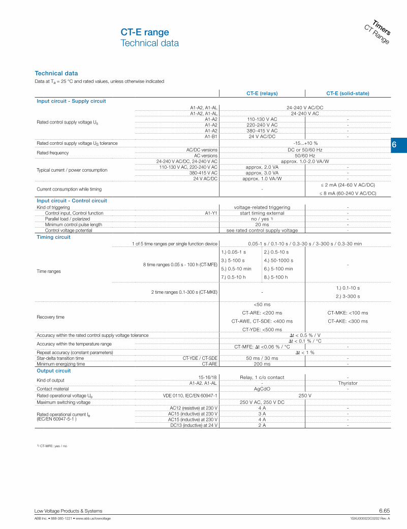
6
TimersCT Range
Low Voltage Products & Systems 6.65ABB Inc. • 888-385-1221 • www.abb.us/lowvoltage 1SXU000023C0202 Rev. A
CT-E rangeTechnical data
Technical dataData at Ta = 25 °C and rated values, unless otherwise indicated
CT-E (relays) CT-E (solid-state)
Input circuit - Supply circuit
Rated control supply voltage Us
A1-A2, A1-AL 24-240 V AC/DCA1-A2, A1-AL 24-240 V AC
A1-A2 110-130 V AC -A1-A2 220-240 V AC -A1-A2 380-415 V AC -A1-B1 24 V AC/DC -
Rated control supply voltage US tolerance -15...+10 %
Rated frequencyAC/DC versions DC or 50/60 Hz
AC versions 50/60 Hz
Typical current / power consumption
24-240 V AC/DC, 24-240 V AC approx. 1.0-2.0 VA/W110-130 V AC, 220-240 V AC approx. 2.0 VA -
380-415 V AC approx. 3.0 VA -24 V AC/DC approx. 1.0 VA/W -
Current consumption while timing -≤ 2 mA (24-60 V AC/DC)
≤ 8 mA (60-240 V AC/DC)
Input circuit - Control circuitKind of triggering voltage-related triggering -
Control input, Control function A1-Y1 start timing external -Parallel load / polarized no / yes 1) -Minimum control pulse length 20 ms -Control voltage potential see rated control supply voltage -
Timing circuit
Time ranges
1 of 5 time ranges per single function device 0.05-1 s / 0.1-10 s / 0.3-30 s / 3-300 s / 0.3-30 min
8 time ranges 0.05 s - 100 h (CT-MFE)
1.) 0.05-1 s
3.) 5-100 s
5.) 0.5-10 min
7.) 0.5-10 h
2.) 0.5-10 s
4.) 50-1000 s
6.) 5-100 min
8.) 5-100 h
-
2 time ranges 0.1-300 s (CT-MKE) -1.) 0.1-10 s
2.) 3-300 s
Recovery time
<50 ms
CT-ARE: <200 ms
CT-AWE, CT-SDE: <400 ms
CT-YDE: <500 ms
CT-MKE: <100 ms
CT-AKE: <300 ms
Accuracy within the rated control supply voltage tolerance it < 0.5 % / V
Accuracy within the temperature rangeit < 0.1 % / °C
CT-MFE: it <0.06 % / °C -Repeat accuracy (constant parameters) it < 1 %Star-delta transition time CT-YDE / CT-SDE 50 ms / 30 ms -Minimum energizing time CT-ARE 200 ms -Output circuit
Kind of output15-16/18 Relay, 1 c/o contact -
A1-A2. A1-AL - ThyristorContact material AgCdO -Rated operational voltage Ue VDE 0110, IEC/EN 60947-1 250 VMaximum switching voltage 250 V AC, 250 V DC
Rated operational current Ie (IEC/EN 60947-5-1 )
AC12 (resistive) at 230 V 4 A -AC15 (inductive) at 230 V 3 A -AC15 (inductive) at 230 V 4 A -DC13 (inductive) at 24 V 2 A -
1) CT-MFE: yes / no

6
Timers
CT Range
6.66 Low Voltage Products & Systems
1SXU000023C0202 Rev. A ABB Inc. • 888-385-1221 • www.abb.us/lowvoltage
CT-E rangeTechnical data
CT-E (relays) CT-E (solid-state)
AC rating (UL 508)
Utilization category (Control Circuit Rating Code) B 300 -
max. rated operational voltage 300 V AC -
Maximum continuous thermal current at B300 5 A -
max. making/breaking apparent power at B300 3600 VA / 360 VA -
Mechanical lifetime 30 x 106 switching cycles -Electrical lifetime at AC12, 230 V, 4 A 0.1 x 10⁶ switching cycles -Max. fuse rating to achieve short-circuit protection (IEC/EN 60947-5-1)
n/c contact 10 A fast-acting, CT-ARE: 5 A -n/o contact 10 A fast-acting, CT-ARE: 5 A -
Minimum load current -CT-MKE: 20 mA
CT-EKE, CT-AKE: 10 mA
Maximum load current -CT-MKE: ≤ 0.8 A at Ta = ≤ 20 °C
CT-EKE, CT-AKE: ≤ 0.7 A
Load current reduction / Derating - 10 mA/°C
Maximum surge current -CT-MKE: 20 A for t 20 ms
CT-EKE, CT-AKE: 15 AVoltage drop in connected state - ≤ 3 V
Cable length between solid-state timer andconnected load at 50 Hz and a cable capacity of100 pF/m :
at 24 V AC - 220 m / 22 nFat 42 V AC - 100 m / 10 nFat 60 V AC - 65 m / 6.5 nF
at 110 V AC - 50 m / 5 nFat 240 V AC - 22 m / 2.2 nF
General dataDuty time 100%
Dimensions (W x H x D) 22.5 x 78.5 x 78 mm (0.886 x 3.09 x 3.07 in)
Weight approx. 80 g (0.176 lb)Mounting DIN rail (IEC/EN 60715)Mounting position anyMinimum distance to other units horizontal / vertical no / noDegree of protection housing / terminals IP50 / IP20Electrical connection
Wire sizefine-strand with wire end ferrule 2 x 0.75-1.5 mm2 (2 x 18-16 AWG)fine-strand without wire end ferrule 2 x 1-1.5 mm2 (2 x 18-16 AWG)rigid 2 x 0.75-1.5 mm2 (2 x 18-16 AWG)
Stripping length 10 mm (0.39 in)Tightening torque 0.6-0.8 NmEnvironmental dataAmbient temperature ranges operation / storage -20...+60 °C / -40...+85 °CDamp heat IEC 68-2-30 24 h cycles, 55 °C, 93 % rel., 96 hOperational reliability IEC 68-2-6 6 gMechanical resistance IEC 68-2-6 10 gIsolation dataRated impulse withstand voltage Uimp between all isolated circuits VDE 0110, IEC/EN 664 4 kV; 1.2/50 µs
Pollution category VDE 0110, IEC 664, IEC 255-5 III/COvervoltage category VDE 0110, IEC 664, IEC 255-5 III/CRated insulation voltage Ui between supply circuit, control circuit and output circuit input circuit / output circuit
300 V (supply up to 240 V)500 V (supply up to 440 V)
Test voltage between all isolated circuits type test 2.5 kV, 50 Hz, 1 s
StandardsProduct standard IEC 61812-1, EN 61812-1 + A11, DIN VDE 0435 Teil 2021Low Voltage Directive 2006/95/ECEMC Directive 2004/108/ECElectromagnetic compatibilityInterference immunity to IEC/EN 61000-6-2
electronic discharge IEC/EN 61000-4-2 Level 3 (6 kV / 8 kV)radiated, radio-frequencyelectromagnetic field IEC/EN 61000-4-3 Level 3 (10 V/m)
electrical fast transient/burst IEC/EN 61000-4-4 Level 3 (2 kV / 5 kHz)surge IEC/EN 61000-4-5 Level 3 (2 kV L-L)conducted disturbances, induced by radio-frequency fields IEC/EN 61000-4-6 Level 3 (10 V)
Interference emissions IEC/EN 61000-6-4

6
TimersCT Range
Low Voltage Products & Systems 6.67ABB Inc. • 888-385-1221 • www.abb.us/lowvoltage 1SXU000023C0202 Rev. A
CT-E rangeTechnical diagrams
220 V 50 Hz 1 AC360 cycles/h
300
200
1008060504030
20
101 2 4 6 10
I A
V
U
0,1 0,2 0,5
cos ϕ
F
0,5
0,1 0,2 0,3 0,4 0,5 0,6 0,7 0,8 0,9 1,0
0,6
0,7
0,8
0,9
1,0
300
200
1008060504030
20
101 2 4 6 10
I A
V
U
0,1 0,2 0,5
4321105
2
3 4
N
I A
5
8 9
106
5 6 7 8
AC load (resistive) DC load (resistive)
Technical diagramsLoad limit curves
Derating factor F for inductive AC load Contact lifetime

6
Timers
CT Range
6.68 Low Voltage Products & Systems
1SXU000023C0202 Rev. A ABB Inc. • 888-385-1221 • www.abb.us/lowvoltage
CT-E rangeWiring notesApproximate dimensions
3.48“
3.19“
3.09“
.886“
3.07
“
88,5
81
78,5
78
22,5
A1 Y1
A2
I
I
I
U
A1
A2
Y1
U
Dimensional drawing Dimensions in mm
Wiring notesfor single-function devices with control contact (CT-AHE, CT-AWE with auxiliary voltage)
I
IA1
A2
Y1
IU A1 Y1
A2
U
6
TimersCT Range
Low Voltage Products & Systems 6.69ABB Inc. • 888-385-1221 • www.abb.us/lowvoltage 1SXU000023C0202 Rev. A
CT-S Range
Elec
troni
c tim
ers
CT-
S R
ange
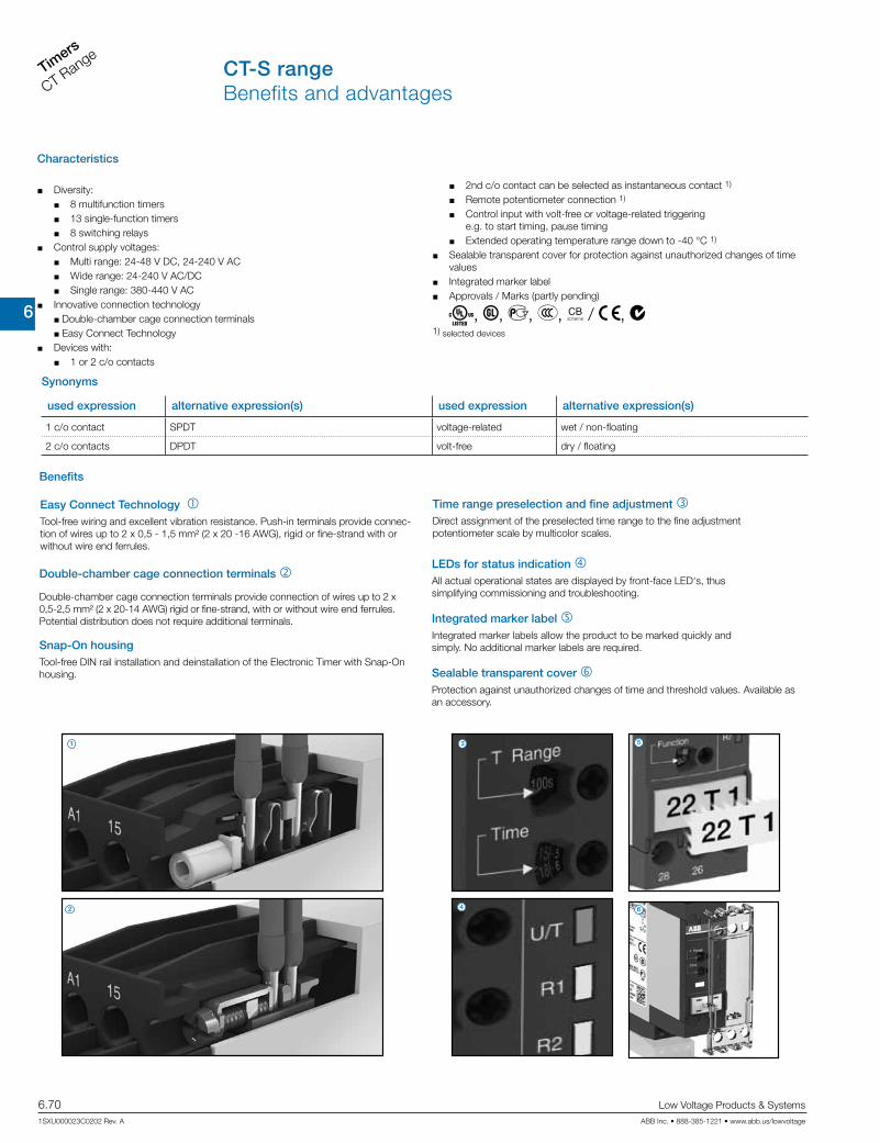
6
Timers
CT Range
6.70 Low Voltage Products & Systems
1SXU000023C0202 Rev. A ABB Inc. • 888-385-1221 • www.abb.us/lowvoltage
CT-S rangeBenefits and advantages
Characteristics
J Diversity:J 8 multifunction timersJ 13 single-function timersJ 8 switching relays
J Control supply voltages:J Multi range: 24-48 V DC, 24-240 V ACJ Wide range: 24-240 V AC/DCJ Single range: 380-440 V AC
J Innovative connection technologyJ Double-chamber cage connection terminalsJ Easy Connect Technology
J Devices with:J 1 or 2 c/o contacts
Easy Connect Technology 1 Tool-free wiring and excellent vibration resistance. Push-in terminals provide connec-tion of wires up to 2 x 0,5 - 1,5 mm² (2 x 20 -16 AWG), rigid or fine-strand with or without wire end ferrules.
Double-chamber cage connection terminals 2
Double-chamber cage connection terminals provide connection of wires up to 2 x 0,5-2,5 mm² (2 x 20-14 AWG) rigid or fine-strand, with or without wire end ferrules. Potential distribution does not require additional terminals.
Snap-On housingTool-free DIN rail installation and deinstallation of the Electronic Timer with Snap-On housing.
Time range preselection and fine adjustment 3Direct assignment of the preselected time range to the fine adjustment potentiometer scale by multicolor scales.
LEDs for status indication 4All actual operational states are displayed by front-face LED‘s, thus simplifying commissioning and troubleshooting.
Integrated marker label 5Integrated marker labels allow the product to be marked quickly and simply. No additional marker labels are required.
Sealable transparent cover 6Protection against unauthorized changes of time and threshold values. Available as an accessory.
Benefits
J 2nd c/o contact can be selected as instantaneous contact 1)
J Remote potentiometer connection 1)
J Control input with volt-free or voltage-related triggering e.g. to start timing, pause timingJ Extended operating temperature range down to -40 °C 1)
J Sealable transparent cover for protection against unauthorized changes of time values
J Integrated marker labelJ Approvals / Marks (partly pending)
A, C, D, E, K / a, b1) selected devices
Synonyms
used expression alternative expression(s) used expression alternative expression(s)
1 c/o contact SPDT voltage-related wet / non-floating
2 c/o contacts DPDT volt-free dry / floating
1
2
3
4
5
6

6
TimersCT Range
Low Voltage Products & Systems 6.71ABB Inc. • 888-385-1221 • www.abb.us/lowvoltage 1SXU000023C0202 Rev. A
CT-S range Conversion table
ABB’s electronic timers in a new housing Benefits at a glance
Double-chamber cage connection terminals
Easy conversions:The predecessor range of electronic timers is replaced by an identical range of electronic timers with double-chamber cage connection terminals. The Reference code has changed in one digit only: 1SVRx changed to 1SVR7.
Ratings:Double-chamber cage connection terminals provide connection of wires up to 1 x 0,5-4 mm² (1 x 20-12 AWG) or 2 x 0,5-2,5 mm² (2 x 20-14 AWG) rigid or 1 x 0,5-2,5 mm² (1 x 20-14 AWG) / 2 x 0,5-1,5 mm² (2 x 20 -16 AWG), rigid or fine-strand, with or without wire end ferrules. Potential distribution does not require additional terminals.
Extended type designatorsThe references with push-in terminals or screw terminals can be differentiated eas-ily by the extended type designator: CT-xxS.xxS indicates the screw terminalCT-xxS.xxP indicates the push-in terminal
Easy Connect Technology
New Options:In addition to our existing well established screw connections, ABB introduces a new innovative connection technology: Easy Connect Technology with push-in terminals.
Tool-Free Wiring:The push-in terminals can be wired with rigid or fine-strand wires with wire end fer-rules totally tool-free. The connection direction is exactly the same as for the screw version.
Higher utility class:The Easy Connect Technology provides excellent vibration resistance with gas tight push-in terminals – the right solution for harsh environment.
Ratings:Push-in terminals provide connection of wires up to 2 x 0,5 - 1,5 mm² (2 x 20-16 AWG), rigid or fine-strand with or without wire end ferrules.
Previous Generation New Generation
Double-chamber cage connection terminals Easy Connect Technology
1SVR630010R0200 CT-MFS.21 1SVR730010R0200 CT-MFS.21S 1SVR740010R0200 CT-MFS.21P
1SVR630010R3200 CT-MBS.22 1SVR730010R3200 CT-MBS.22S 1SVR740010R3200 CT-MBS.22P
1SVR630020R0200 CT-MVS.21 1SVR730020R0200 CT-MVS.21S 1SVR740020R0200 CT-MVS.21P
1SVR630020R3100 CT-MVS.12 1SVR730020R3100 CT-MVS.12S 1SVR740020R3100 CT-MVS.12P
1SVR630020R3300 CT-MVS.22 1SVR730020R3300 CT-MVS.22S 1SVR740020R3300 CT-MVS.22P
1SVR630021R2300 CT-MVS.23 1SVR730021R2300 CT-MVS.23S 1SVR740021R2300 CT-MVS.23P
1SVR630030R3300 CT-MXS.22 1SVR730030R3300 CT-MXS.22S 1SVR740030R3300 CT-MXS.22P
1SVR630040R3300 CT-WBS.22 1SVR730040R3300 CT-WBS.22S 1SVR740040R3300 CT-WBS.22P
1SVR630100R0300 CT-ERS.21 1SVR730100R0300 CT-ERS.21S 1SVR740100R0300 CT-ERS.21P
1SVR630100R3100 CT-ERS.12 1SVR730100R3100 CT-ERS.12S 1SVR740100R3100 CT-ERS.12P
1SVR630100R3300 CT-ERS.22 1SVR730100R3300 CT-ERS.22S 1SVR740100R3300 CT-ERS.22P
1SVR630110R3300 CT-AHS.22 1SVR730110R3300 CT-AHS.22S 1SVR740110R3300 CT-AHS.22P
1SVR630120R3100 CT-ARS.11 1SVR730120R3100 CT-ARS.11S 1SVR740120R3100 CT-ARS.11P
1SVR630120R3300 CT-ARS.21 1SVR730120R3300 CT-ARS.21S 1SVR740120R3300 CT-ARS.21P
1SVR630180R0300 CT-APS.21 1SVR730180R0300 CT-APS.21S 1SVR740180R0300 CT-APS.21P
1SVR630180R3100 CT-APS.12 1SVR730180R3100 CT-APS.12S 1SVR740180R3100 CT-APS.12P
1SVR630180R3300 CT-APS.22 1SVR730180R3300 CT-APS.22S 1SVR740180R3300 CT-APS.22P
1SVR630210R3300 CT-SDS.22 1SVR730210R3300 CT-SDS.22S 1SVR740210R3300 CT-SDS.22P
1SVR630211R2300 CT-SDS.23 1SVR730211R2300 CT-SDS.23S 1SVR740211R2300 CT-SDS.23P

6
Timers
CT Range
6.72 Low Voltage Products & Systems
1SXU000023C0202 Rev. A ABB Inc. • 888-385-1221 • www.abb.us/lowvoltage
CT-S range Ordering details
Time function
Rated control supply
voltage
Time ranges
Control input OutputReference
codeCatalognumber
Weight(1 pce)
kg (lb)
A B
AB CA CBEFCHA+G
24-240 V AC/DC 2)
3) 4)
10 (0.05 s- 300 h)
2 c/o
CT-MVS.21S 1SVR730020R02000.148 (0.326)
CT-MVS.21P 1SVR740020R02000.136 (0.300)
24-48 V DC,24-240 V AC
CT-MVS.22S 1SVR730020R33000.142 (0.313)
CT-MVS.22P 1SVR740020R33000.131 (0.289)
380-440 V AC
CT-MVS.23S 1SVR730021R23000.144 (0.317)
CT-MVS.23P 1SVR740021R23000.133 (0.293)
A B
AB CA CBEHA+G
24-48 V DC,24-240 V AC
10 (0.05 s- 300 h)
1 c/o
CT-MVS.12S 1SVR730020R31000.107 (0.236)
CT-MVS.12P 1SVR740020R31000.102 (0.225)
AB 1)
CE
E
A+AC
BC
G
24-48 V DC,24-240 V AC
5)
2 x 10 (0.05 s- 300 h)
2 c/o
CT-MXS.22S 1SVR730030R33000.142 (0.313)
CT-MXS.22P 1SVR740030R33000.131 (0.289)
A B
AB CA CBA
B FCHG
24-240 V AC/DC 2)
3) 4)
10 (0.05 s- 300 h)
2 c/o
CT-MFS.21S 1SVR730010R02000.145 (0.320)
CT-MFS.21P 1SVR740010R02000.133 (0.293)
24-48 V DC,24-240 V AC
3) 4)
10 (0.05 s- 300 h) / 2 c/o
CT-MBS.22S 1SVR730010R32000.140 (0.309)
CT-MBS.22P 1SVR740010R32000.129 (0.284)
CT-MVS.21P
CT-MBS.22P
1) Asymmetrical ON- and OFF-delay2) Extended temperature range -40 °C3) Remote potentiometer connection4) 2nd c/o contact selectable as instantaneous contact5) 2 remote potentiometer connections
Control input with voltage-related triggering Control input with volt-free triggering
DescriptionThe highly sophisticated CT-S range in ABB’s new S-range housing offers two different types of connection terminals and is ideally suited for universal use. Two different connection technologies are available:• Double-chamber cage connection terminals: • Easy Connect Technology:
Accessories:The CT-S range offers the possibility of using accessories such as a remote potentiometer to adjust the time delay or a sealable, transparent cover to protect against unauthorized changes. of time and threshold values.
Ordering details
A(+) ON-delay (accumulative) B OFF-delay without aux. voltage CA Impulse-ON CB Impulse-OFFAB Symmetrical ON-delay and OFF-delay A Flasher starting with ON
B Flasher staring with OFFE Pulse generator startingFC Star-delta change-over with impulseH Pulse former
G ON/OFF-functionFA Star-delta change-over twice ON-delayed with ON or OFFE Pulse generator starting with ON or OFFEC Single-pulse generatorCE Impulse-ON/OFF
A Flasher starting with ONB Flasher starting with OFFAC fixed impulse with adjustable time delayBC Adjustable impulse with fixed time delay

6
TimersCT Range
Low Voltage Products & Systems 6.73ABB Inc. • 888-385-1221 • www.abb.us/lowvoltage 1SXU000023C0202 Rev. A
Control input with voltage-related triggering Control input with volt-free triggering
CT-S rangeOrdering details
1) Asymmetrical ON- and OFF-delay2) Extended temperature range -40 °C3) Remote potentiometer connection4) 2nd c/o contact selectable as instantaneously contact5) 2 remote potentiometer connections6) Without auxiliary voltage7) 50 ms transition time8) For DC contactor coils
CT-ERS.21P
CT-AHS.22P
Time function
Rated control supply
voltage
Time ranges
Control input OutputReference
codeCatalognumber
Weight(1 pce)
kg (lb)
ACA
ABG
ACBC
24-48 V DC,24-240 V AC
10 (0.05 s- 300 h)
2 c/o
CT-WBS.22S 1SVR730040R33000.123 (0.271)
CT-WBS.22P 1SVR740040R33000.115 (0.254)
A
24-240 V AC/DC 2)
10 (0.05 s- 300 h)
2 c/o
CT-ERS.21S 1SVR730100R03000.130 (0.287)
CT-ERS.21P 1SVR740100R03000.121 (0.267)
24-48 V DC,24-240 V AC
CT-ERS.22S 1SVR730100R33000.121 (0.267)
CT-ERS.22P 1SVR740100R33000.113 (0.249)
24-48 V DC,24-240 V AC
1 c/oCT-ERS.12S 1SVR730100R3100
0.106 (0.234)
CT-ERS.12P 1SVR740100R31000.101 (0.222)
B
24-240 V AC/DC 2)
10 (0.05 s- 300 h)
2 c/o
CT-APS.21S 1SVR730180R03000.146 (0.322)
CT-APS.21P 1SVR740180R03000.125 (0.276)
24-48 V DC,24-240 V AC
CT-APS.22S 1SVR730180R33000.138 (0.304)
CT-APS.22P 1SVR740180R33000.127 (0.280)
1 c/oCT-APS.12S 1SVR730180R3100
0.109 (0.240)
CT-APS.12P 1SVR740180R31000.103 (0.227)
24-48 V DC,24-240 V AC
10 (0.05 s- 300 h)
2 c/oCT-AHS.22S 1SVR730110R3300
0.136 (0.300)
CT-AHS.22P 1SVR740110R33000.125 (0.276)
B 6) 24-240 V AC/DC
7 (0.05 s- 10 min)
1 c/oCT-ARS.11S 1SVR730120R3100
0.106 (0.234)
CT-ARS.11P 1SVR740120R31000.100 (0.220)
2 c/oCT-ARS.21S 1SVR730120R3300
0.124 (0.273)
CT-ARS.21P 1SVR740120R33000.115 (0.254)
B 6)
110-127 V AC or
110 V DC 8)CT-VBS.17 1SVR430261R6000
0.123 (0.271)
200-240 V AC/DC 8) CT-VBS.18 1SVR430261R5000
0.118 (0.260)
F7)
24-48 V DC,24-240 V AC
7 (0.05 s- 10 min)
2 n/o
CT-SDS.22S 1SVR730210R33000.114 (0.251)
CT-SDS.22P 1SVR740210R33000.108 (0.238)
380-440 V AC
CT-SDS.23S 1SVR730211R23000.118 (0.260)
CT-SDS.23P 1SVR740211R23000.112 (0.247)
CT-SDS.23P
Control input with voltage-related triggering Control input with volt-free triggering
A(+) ON-delay (accumulative) B OFF-delay without aux. voltage CA Impulse-ON A Flasher starting with ON
B Flasher staring with OFF
G ON/OFF-function
CE Impulse-ON/OFF
A Flasher starting with ONB Flasher starting with OFFAC fixed impulse with adjustable time delayBC Adjustable impulse with fixed time delayF Star-delta change-over
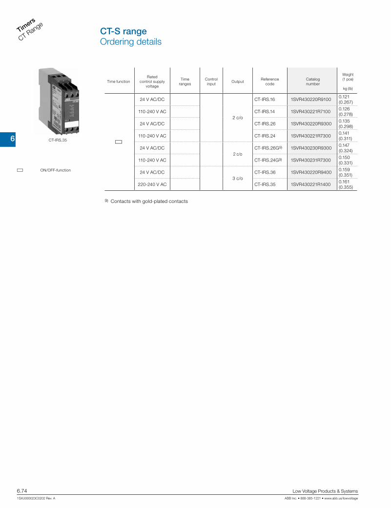
6
Timers
CT Range
6.74 Low Voltage Products & Systems
1SXU000023C0202 Rev. A ABB Inc. • 888-385-1221 • www.abb.us/lowvoltage
CT-S rangeOrdering details
Time functionRated
control supply voltage
Time ranges
Control input
OutputReference
codeCatalognumber
Weight(1 pce)
kg (lb)
G
24 V AC/DC
2 c/o
CT-IRS.16 1SVR430220R91000.121 (0.267)
110-240 V AC CT-IRS.14 1SVR430221R71000.126 (0.278)
24 V AC/DC CT-IRS.26 1SVR430220R93000.135 (0.298)
110-240 V AC CT-IRS.24 1SVR430221R73000.141 (0.311)
24 V AC/DC2 c/o
CT-IRS.26G9) 1SVR430230R93000.147 (0.324)
110-240 V AC CT-IRS.24G9) 1SVR430231R73000.150 (0.331)
24 V AC/DC3 c/o
CT-IRS.36 1SVR430220R94000.159 (0.351)
220-240 V AC CT-IRS.35 1SVR430221R14000.161 (0.355)
CT-IRS.35
9) Contacts with gold-plated contacts
G ON/OFF-function

6
TimersCT Range
Low Voltage Products & Systems 6.75ABB Inc. • 888-385-1221 • www.abb.us/lowvoltage 1SXU000023C0202 Rev. A
CT-S rangeOrdering detailsAccessories
Marker label 29.6 x 44.5 mm
Marker label with scale 0-10 48.5 x 44.5 mm
Marker label with scale 0-30 48.5 x 44.5 mm
30
1512
9
6
3
18
27
21
24
0
MT-x50B
30 mm adapters
CT-S time relay Potentiometers
Z2
Z3Z1
Note: The connections of the potentiometer are not marked.
Remote potentiometer 50 kq ±20 % - 0,2 q, degree of protection IP66
Material
Diameter
in mm
Referencecode
Catalognumber
Pack.- unit
pieces
Weight 1 piece
g / oz
Plastic, black 22.5 MT-150B 1SFA611410R1506 1 0.040
Plastic, chrome 22.5 MT-250B 1SFA611410R2506 1 0.040
Metal, chrome 22.5 MT-350B 1SFA611410R3506 1 0.048
30 mm adapter for attaching the potentiometer 22 mm in 30 mm mounting hole
Marker label
MaterialReference
codeCatalognumber
Pack.- unit
pieces
Weight 1 piece
g / oz
Plastic, black KA1-8029 1SFA616920R8029 1
Metal, chrome KA1-8030 1SFA616920R8030 1
CaptionReference
codeCatalognumber
Pack.- unit
pieces
Weight 1 piece
g / oz
Symbol (see illustration) SK 615 562-87 GJD6155620R0087 1 0.002
Scale 0 - 10 SK 615 562-88 GJD6155620R0088 1 0.002
Scale 0 - 30 MA16-1060 1SFA611940R1060 1 0.002

6
Timers
CT Range
6.76 Low Voltage Products & Systems
1SXU000023C0202 Rev. A ABB Inc. • 888-385-1221 • www.abb.us/lowvoltage
CT-S rangeOrdering detailsAccessories
4,5 62,5
60
1011
,5
22,5
.177
”
2.46”
2.36”
.394
”
.886
”
.453
”
22,5
68,5
73,5
.886”
2.70
”
.138”.275”
front-to-backsize 107
22.5 0.89”
68
2.68
”
110.5 4.31”
8 0.32”
4.8 0.19”
front to back
203A11 8
.315
”
.787”
21
18
80.
314“
0.709“
0.827“
4T22
ADP.01
COV.01
COV.11
MAR.01
MAR.02
Marker label
Accessories
Material for devicesReference
codeCatalognumber
Pack.- unit
pieces
Weight 1 piece
g / oz
Adapter for screw mounting1) CT-S
22.5 mm
ADP.01 1SVR430029R0100 1 18.4/0.65
Sealable transparent cover
COV.01 1SVR430005R0100 1 5.2/0.18
Sealable transparent cover1) CT-S.S/P 22.5 mm COV.11 1SVR730005R0100 1 4 / 0.129
Material for devicesReference
codeCatalognumber
Pack.- unit
pieces
Weight 1 piece
g / oz
MarkerCT-S without DIP switch
MAR.01 1SVR366017R0100 10 0.19/0.007
Marker CT-S with DIP switch MAR.02 1SVR430043R0000 10 0.13/0.005
MarkerCT-S.S/P with
DIP switchMAR.12 1SVR730006R0000 10 0.152/0.335
1) also available for CT-S.S/P

6
TimersCT Range
Low Voltage Products & Systems 6.77ABB Inc. • 888-385-1221 • www.abb.us/lowvoltage 1SXU000023C0202 Rev. A
CT-S rangeFunction diagrams
A ON-delay (Delay on make) CT-MVS, CT-ERS, CT-WBS
A ON-delay (Delay on make) CT-MFS, CT-MBS
A1-A2
15-16, 25-26
21-2421-22
15-18, 25-28
t < tgreen LED
t = adjusted time delayA1-A2
15-16, 25-26
21-2421-22
15-18, 25-28
t1 t3 t2t
X1-Z2
Y1-Z2
green LED
t = adjusted time delay t1 + t2 = tt3 = pause timing
This function requires continuous control supply voltage for timing. Timing begins when control supply voltage is applied. The green LED flashes dur-ing timing. When the selected time delay is complete, the output relay energizes and the flashing green LED turns steady. If control supply voltage is interrupted, the output relay de-energizes and the time delay is reset.
This function requires continuous control supply voltage for timing. If control input Y1-Z2 is open, timing begins when control supply voltage is ap-plied. Or, if control supply voltage is already applied, opening control input Y1-Z2 also starts timing. The green LED flashes during timing. When the selected time delay is complete, the output relay energizes and the flashing green LED turns steady. If control input Y1-Z2 closes before the time delay is complete, the time delay is reset and the output relay remains de-energized.Pause timing / Accumulative ON-delay (CT-MFS): Timing can be paused by closing control input X1-Z2. The elapsed time t1 is stored and continues from this time value when X1-Z2 is re-opened. This can be repeated as often as required.If control supply voltage is interrupted, the output relay de-energizes and the time delay is reset.
Remarks
Legend
G Control supply voltage not applied / Output contact open
B Control supply voltage applied / Output contact closed
A1-Y1/B1 Control input with voltage-related triggering Y1-Z2 Control input with volt-free triggeringX1-Z2 Control input with volt-free triggering
Remote potentiometer connection:When an external potentiometer is connected to the remote potentiometer connec-tion (terminals Z1-Z2, Z3-Z2 respectively), the internal, front-face potentiometer is disabled and the time adjustment is made via the external potentiometer.
2nd c/o contact selectable as instantaneous contact:When switch position Inst. “I” is selected, the functionality of the 2nd c/o contact changes to an instantaneous contact. It acts like the c/o contacts of a switching relay, i.e. applying or interrupting the control supply voltage energizes or de-energizes the c/o contact. The designation of the 2nd c/o contact changes from 25-26/28 to 21-22/24, when selected as instantaneous contact.
Terminal designations on the device and in the diagrams:The 1st c/o contact is always designated 15-16/18.The 2nd c/o contact is designated 25-26/28, if it responds to the time delay. If the 2nd c/o contact is selected as an instantaneous contact, the designation 25-26/28 is replaced by 21-22/24. Control supply voltage is always applied to terminals A1-A2.
Function of the yellow LEDs:On devices without the function ‘2nd c/o contact selectable as instantaneous con-tact’, the yellow LED R glows as soon as the output relay energizes and turns off when the output relay de-energizes.
Devices with the function ‘2nd c/o contact selectable as instantaneous contact’ have two yellow LEDs, designated R1 and R2. LED R1 shows the status of the 1st c/o contact (15-16/18) and LED R2 shows the status of the 2nd c/o contact (25-26/28, 21-22/24 resp.). LED R1 or R2 glow as soon as the corresponding output relay ener-gizes and turns off when the corresponding output relay de-energizes.

6
Timers
CT Range
6.78 Low Voltage Products & Systems
1SXU000023C0202 Rev. A ABB Inc. • 888-385-1221 • www.abb.us/lowvoltage
B OFF-delay with auxiliary voltage (Delay on break) CT-MFS, CT-MBS, CT-AHS
A1-A2
15-16, 25-26
21-2421-22
15-18, 25-28
t1 t3 t2t
X1-Z2
Y1-Z2
green LED
t = adjusted time delay t1 + t2 = tt3 = pause timing
A+ Accumulative ON-delay (Accumulative delay on make) CT-MVS
A1-A2
15-16, 25-26
21-2421-22
15-18, 25-28
t1 t3 t2t
A1-Y1/B1
green LED
t = adjusted time delay t1 + t2 = tt3 = pause timing
This function requires continuous control supply voltage for timing. Timing begins when control supply voltage is applied. The green LED flashes during timing. When the selected time delay is complete, the output relay energizes and the flashing green LED turns steady. Timing can be paused by closing control input A1-Y1/B1. The elapsed time t1 is stored and continues from this time value when A1-Y1/B1 is re-opened. This can be repeated as often as required.If control supply voltage is interrupted, the output relay de-energizes and the time delay is reset.
This function requires continuous control supply voltage for timing. If control input Y1-Z2 is closed, the output relay energizes immediately. If control input Y1-Z2 is opened, the time delay starts. The green LED flashes during timing. When the selected time delay is complete, the output relay de- energizes and the flashing green LED turns steady. If control input Y1-Z2 closes before the time delay is complete, the time delay is reset and the output relay does not change state. Timing starts again when control input Y1-Z2 re-opens.Pause timing / Accumulative OFF-delay (CT-MFS): Timing can be paused by closing control input X1-Z2. The elapsed time t1 is stored and continues from this time value when X1-Z2 is re-opened. This can be repeated as often as required.If control supply voltage is interrupted, the output relay de-energizes and the time delay is reset.
B OFF-delay with auxiliary voltage (Delay on break) CT-MVS, CT-APS
A1-A2
15-16, 25-26
21-2421-22
15-18, 25-28
t
A1-Y1/B1
< tgreen LED
t = adjusted time delay
B OFF-delay without auxiliary voltage (True delay on break) CT-ARS
A1-A2
15-16, 25-2615-18, 25-28
tgreen LED
t = adjusted time delay
This function requires continuous control supply voltage for timing. If control input A1-Y1/B1 is closed, the output relay energizes immediately. If control input A1-Y1/B1 is opened, the time delay starts. The green LED flashes during tim-ing. When the selected time delay is complete, the output relay de-energizes and the flashing green LED turns steady. If control input A1-Y1/B1 recloses before the time delay is complete, the time delay is reset and the output relay does not change state. Timing starts again when control input A1-Y1/B1 re-opens.If control supply voltage is interrupted, the output relay de-energizes and the time delay is reset.
The OFF-delay function without auxiliary voltage does not require continuous control supply voltage for timing. After a storage time of several months without any voltage, a formatting time of about 5 minutes is necessary. Applying control supply voltage energizes the output relay immediately. Applied con-trol supply voltage is displayed by the glowing green LED. If control supply voltage is interrupted, the OFF-delay starts and the LED turns off. When timing is complete, the output relay de-energizes. For correct operation of the unit, it is necessary to complete the minimum energizing time. As soon as timing starts, the LED turns off.
CT-S rangeFunction diagrams
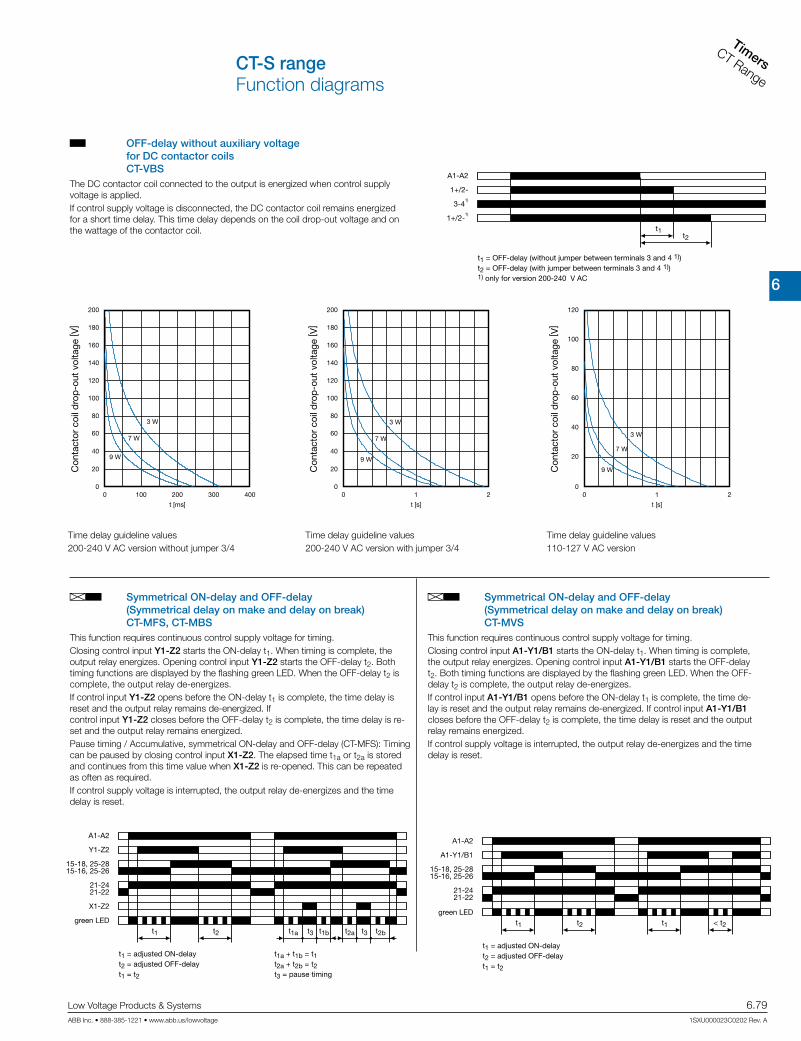
6
TimersCT Range
Low Voltage Products & Systems 6.79ABB Inc. • 888-385-1221 • www.abb.us/lowvoltage 1SXU000023C0202 Rev. A
CT-S rangeFunction diagrams
AB Symmetrical ON-delay and OFF-delay (Symmetrical delay on make and delay on break) CT-MFS, CT-MBS
A1-A2
15-16, 25-26
21-2421-22
15-18, 25-28
t1a t3 t1bt1
X1-Z2
Y1-Z2
t2 t2a t3 t2b
green LED
t1 = adjusted ON-delayt2 = adjusted OFF-delayt1 = t2
t1a + t1b = t1t2a + t2b = t2t3 = pause timing
AB Symmetrical ON-delay and OFF-delay (Symmetrical delay on make and delay on break) CT-MVS
A1-A2
15-16, 25-26
21-2421-22
15-18, 25-28
t1
A1-Y1/B1
t2 t1 < t2
green LED
t1 = adjusted ON-delayt2 = adjusted OFF-delayt1 = t2
This function requires continuous control supply voltage for timing. Closing control input Y1-Z2 starts the ON-delay t1. When timing is complete, the output relay energizes. Opening control input Y1-Z2 starts the OFF-delay t2. Both timing functions are displayed by the flashing green LED. When the OFF-delay t2 is complete, the output relay de-energizes.If control input Y1-Z2 opens before the ON-delay t1 is complete, the time delay is reset and the output relay remains de-energized. If control input Y1-Z2 closes before the OFF-delay t2 is complete, the time delay is re-set and the output relay remains energized. Pause timing / Accumulative, symmetrical ON-delay and OFF-delay (CT-MFS): Timing can be paused by closing control input X1-Z2. The elapsed time t1a or t2a is stored and continues from this time value when X1-Z2 is re-opened. This can be repeated as often as required.If control supply voltage is interrupted, the output relay de-energizes and the time delay is reset.
This function requires continuous control supply voltage for timing. Closing control input A1-Y1/B1 starts the ON-delay t1. When timing is complete, the output relay energizes. Opening control input A1-Y1/B1 starts the OFF-delay t2. Both timing functions are displayed by the flashing green LED. When the OFF-delay t2 is complete, the output relay de-energizes. If control input A1-Y1/B1 opens before the ON-delay t1 is complete, the time de-lay is reset and the output relay remains de-energized. If control input A1-Y1/B1 closes before the OFF-delay t2 is complete, the time delay is reset and the output relay remains energized.If control supply voltage is interrupted, the output relay de-energizes and the time delay is reset.
B OFF-delay without auxiliary voltage for DC contactor coils CT-VBS
A1-A2
3-41)
1+/2-
t1t2
1+/2-1)
t1 = OFF-delay (without jumper between terminals 3 and 4 1))t2 = OFF-delay (with jumper between terminals 3 and 4 1))1) only for version 200-240 V AC
3 W
7 W
9 W
0
20
0
40
60
80
100
120
140
160
180
200
100 200
t [ms]
300 400
Con
tact
or c
oil d
rop
-out
vol
tage
[ V]
3 W
7 W
9 W
0
20
0
40
60
80
100
120
140
160
180
200
1
t [s]
2
Con
tact
or c
oil d
rop
-out
vol
tage
[ V]
3 W
7 W
9 W
00
120
100
80
60
40
20
1
t [s]
2
Con
tact
or c
oil d
rop
-out
vol
tage
[ V]
The DC contactor coil connected to the output is energized when control supply voltage is applied. If control supply voltage is disconnected, the DC contactor coil remains energized for a short time delay. This time delay depends on the coil drop-out voltage and on the wattage of the contactor coil.
Time delay guideline values200-240 V AC version without jumper 3/4
Time delay guideline values200-240 V AC version with jumper 3/4
Time delay guideline values110-127 V AC version

6
Timers
CT Range
6.80 Low Voltage Products & Systems
1SXU000023C0202 Rev. A ABB Inc. • 888-385-1221 • www.abb.us/lowvoltage
CT-S rangeFunction diagrams
CA Impulse-ON (Interval) CT-MVS, CT-WBS
A1-A2
15-16, 25-26
21-2421-22
15-18, 25-28
t < tgreen LED
t = adjusted pulse time
AB Asymmetrical ON-delay and OFF-delay (Asymmetrical delay on make and delay on break) CT-MXS
A1-A2
15-16, 25-2615-18, 25-28
t1
A1-Y1/B1
t2 t1 < t2
green LED
t1 = adjusted ON-delayt2 = adjusted OFF-delayt1 and t2 independently adjustable
This function requires continuous control supply voltage for timing. Closing control input A1-Y1/B1 starts the ON-delay t1. When timing is complete, the output relay energizes. Opening control input A1-Y1/B1 starts the OFF-delay t2. When the OFF-delay is complete, the output relay de-energizes. Both timing func-tions are displayed by the flashing green LED. The ON-delay and OFF-delay are independently adjustable. If control input A1-Y1/B1 opens before the ON-delay is complete (<t1), the time delay is reset and the output relay remains de-energized. If control input A1-Y1/B1 closes before the OFF-delay is complete (<t2), the time de-lay is reset and the output relay remains energized. If control supply voltage is interrupted, the output relay de-energizes and the time delay is reset.
This function requires continuous control supply voltage for timing. The output relay energizes immediately when control supply voltage is applied and de-energizes after the set pulse time is complete. The green LED flashes during timing. When the selected pulse time is complete, the flashing green LED turns steady. If control supply voltage is interrupted, the output relay de-energizes and the time delay is reset.
CA Impulse-ON (Interval) CT-MFS, CT-MBS
CB Impulse-OFF with auxiliary voltage (Trailing edge interval) CT-MFS, CT-MBS
A1-A2
15-16, 25-26
21-2421-22
15-18, 25-28
t1 t3 t2t
X1-Z2
Y1-Z2
green LED
t = adjusted pulse time t1 + t2 = tt3 = pause timing
A1-A2
15-16, 25-26
21-2421-22
15-18, 25-28
t1 t3 t2t
X1-Z2
Y1-Z2
green LED
t = adjusted pulse time t1 + t2 = tt3 = pause timing
This function requires continuous control supply voltage for timing. The output relay energizes immediately when control supply voltage is applied and de-energizes after the set pulse time is complete. If control input Y1-Z2 is open, timing begins when control supply voltage is applied. Or, if control supply voltage is already applied, opening control input Y1-Z2 starts timing. The green LED flashes during timing. When the selected pulse time is complete, the output relay de-energizes and the flashing green LED turns steady. Closing control input Y1-Z2, before the pulse time is complete, de-energizes the output relay and resets the pulse time. Pause timing / Accumulative impulse-ON (CT-MFS): Timing can be paused by closing control input X1-Z2. The elapsed time t1 is stored and continues from this time value when X1-Z2 is re-opened. This can be repeated as often as required.If control supply voltage is interrupted, the output relay de-energizes and the time delay is reset.
This function requires continuous control supply voltage for timing. If control supply voltage is applied, opening control input Y1-Z2 energizes the out-put relay immediately and starts timing. The green LED flashes during timing. When the selected pulse time is complete, the output relay de-energizes and the flashing green LED turns steady. Closing control input Y1-Z2, before the pulse time is complete, de-energizes the output relay and resets the pulse time. Pause timing / Accumulative impulse-OFF (CT-MFS): Timing can be paused by closing control input X1-Z2. The elapsed time t1 is stored and continues from this time value when X1-Z2 is re-opened. This can be repeated as often as required.If control supply voltage is interrupted, the output relay de-energizes and the time delay is reset.

6
TimersCT Range
Low Voltage Products & Systems 6.81ABB Inc. • 888-385-1221 • www.abb.us/lowvoltage 1SXU000023C0202 Rev. A
B Flasher, starting with the OFF time (Recycling equal times, OFF first) CT-WBS
A Flasher, starting with the ON time (Recycling equal times, ON first) CT-WBS
A1-A2
15-16, 25-2615-18, 25-28
t tgreen LED
t = adjusted ashing time
A1-A2
15-16, 25-2615-18, 25-28
t tgreen LED
t = adjusted ashing time
Applying control supply voltage starts timing with symmetrical ON & OFF times. The cycle starts with an ON time first. The ON & OFF times are displayed by the flashing green LED, which flashes twice as fast during the OFF time. If control supply voltage is interrupted, the output relay de-energizes and the time delay is reset.
Applying control supply voltage starts timing with symmetrical ON & OFF times. The cycle starts with an OFF time first. The ON & OFF times are displayed by the flashing green LED, which flashes twice as fast during the OFF time. If control supply voltage is interrupted, the output relay de-energizes and the time delay is reset.
CB Impulse-OFF with auxiliary voltage (Trailing edge interval) CT-MVS
CE Impulse-ON and impulse-OFF (Interval and trailing edge interval) CT-MXS
A1-A2
15-16, 25-26
21-2421-22
15-18, 25-28
t
A1-Y1/B1
< tgreen LED
t = adjusted pulse time
A1-A2
15-16, 25-2615-18, 25-28
t1 < t1t2
A1-Y1/B1
green LED
t1 = adjusted pulse time 1t2 = adjusted pulse time 2
This function requires continuous control supply voltage for timing. If control supply voltage is applied, opening control input A1-Y1/B1 energizes the output relay immediately and starts timing. The green LED flashes during timing. When the selected pulse time is complete, the output relay de-energizes and the flashing green LED turns steady. Closing control input A1-Y1/B1, before the pulse time is complete, de-energizes the output relay and resets the pulse time.If control supply voltage is interrupted, the output relay de-energizes and the time delay is reset.
This function requires continuous control supply voltage for timing. If control supply voltage is applied, closing control input A1-Y1/B1 energizes the output relay immediately and starts the pulse time t1. The green LED flashes during timing. When t1 is complete, the output relay de-energizes and the flashing green LED turns steady. Re-opening control input A1-Y1/B1 energizes the output relay immediately and starts the pulse time t2. The green LED flashes during timing. When t2 is complete, the output relay de-energizes and the flashing green LED turns steady. t1 and t2 are independently adjustable. If control input A1-Y1/B1 changes state before the pulse time is complete, the output relay de-energizes and the pulse time is reset. If control input A1-Y1/B1 changes state again, the interrupted pulse time restarts.If control supply voltage is interrupted, the output relay de-energizes and the time delay is reset.
B Flasher with reset, starting with the OFF time (Recycling equal times with reset, OFF first) CT-MFS, CT-MBS
A1-A2
Y1-Z2
15-16, 25-2615-18, 25-28
21-2221-24
t t t tgreen LED
t = adjusted ashing time
Applying control supply voltage starts timing with symmetrical ON & OFF times. The cycle starts with an OFF time first. The ON & OFF times are displayed by the flashing green LED, which flashes twice as fast during the OFF time. The time delay can be reset by closing control input Y1-Z2. Opening control input Y1-Z2 starts the timer pulsing again with symmetrical ON & OFF times.If control supply voltage is interrupted, the output relay de-energizes and the time delay is reset.
A Flasher with reset, starting with the ON time (Recycling equal times with reset, ON first) CT-MFS, CT-MBS
A1-A2
Y1-Z2
15-16, 25-2615-18, 25-28
21-2221-24
t t t tgreen LED
t = adjusted ashing time
Applying control supply voltage starts timing with symmetrical ON & OFF times. The cycle starts with an ON time first. The ON & OFF times are displayed by the flashing green LED, which flashes twice as fast during the OFF time. The time delay can be reset by closing control input Y1-Z2. Opening control input Y1-Z2 starts the timer pulsing again with symmetrical ON & OFF times.If control supply voltage is interrupted, the output relay de-energizes and the time delay is reset.
CT-S rangeFunction diagrams

6
Timers
CT Range
6.82 Low Voltage Products & Systems
1SXU000023C0202 Rev. A ABB Inc. • 888-385-1221 • www.abb.us/lowvoltage
E Flasher, starting with the ON or OFF time (Recycling equal times, ON or OFF first) CT-MVS
H Pulse former (Single shot) CT-MFS, CT-MBS
A1-A2
A1-Y1/B1
15-16, 25-2615-18, 25-28
21-2221-24
t t t tgreen LED
t = adjusted ashing time
A1-A2
15-16, 25-26
21-2421-22
15-18, 25-28
t t
Y1-Z2
green LED
t = adjusted pulse time
Applying control supply voltage starts timing with symmetrical ON & OFF times. The cycle starts with an ON time first. Closing control input A1-Y1/B1, with control supply voltage applied, starts the cycle with an OFF time first. The ON & OFF times are displayed by the flashing green LED, which flashes twice as fast during the OFF time. If control supply voltage is interrupted, the output relay de-energizes and the time delay is reset.
This function requires continuous control supply voltage for timing. Closing control input Y1-Z2 energizes the output relay immediately and starts tim-ing. Operating the control contact switch Y1-Z2 during the time delay has no ef-fect. The green LED flashes during timing. When the selected ON time is complete, the output relay de-energizes and the flashing green LED turns steady. After the ON time is complete, it can be restarted by closing control input Y1-Z2. If control supply voltage is interrupted, the output relay de-energizes and the time delay is reset.
H Pulse former (Single shot) CT-MVS
A1-A2
15-16, 25-26
21-2421-22
15-18, 25-28
t t
A1-Y1/B1
green LED
t = adjusted pulse time
This function requires continuous control supply voltage for timing. Closing control input A1-Y1/B1 energizes the output relay immediately and starts timing. Operating the control contact switch A1-Y1/B1 during the time delay has no effect. The green LED flashes during timing. When the selected ON time is complete, the output relay de-energizes and the flashing green LED turns steady. After the ON time is complete, it can be restarted by closing control input A1-Y1/B1. If control supply voltage is interrupted, the output relay de-energizes and the time delay is reset.
E Pulse generator, starting with the ON or OFF time (Recycling unequal times, ON or OFF first) CT-MXS
A1-A2
A1-Y1/B1
15-16, 25-2615-18, 25-28
t1 t1t2 t2
green LED
t1 = adjusted OFF timet2 = adjusted ON time
This function requires continuous control supply voltage for timing. Applying control supply voltage, with open control input A1-Y1/B1, starts timing with an ON time t2 first. Applying control supply voltage, with closed control input A1-Y1/B1, starts timing with an OFF time t1 first. The ON & OFF times are dis-played by the flashing green LED, which flashes twice as fast during the OFF time. The ON & OFF times are independently adjustable.If control supply voltage is interrupted, the output relay de-energizes and the time delay is reset.
CT-S rangeFunction diagrams

6
TimersCT Range
Low Voltage Products & Systems 6.83ABB Inc. • 888-385-1221 • www.abb.us/lowvoltage 1SXU000023C0202 Rev. A
CT-S rangeFunction diagrams
EC Single-pulse generator, starting with the OFF time (Delay on make with interval output) CT-MXS
AC Fixed impulse with adjustable time delay (Delayed pulse output) CT-WBS
A1-A2
A1-Y1/B1
15-16, 25-2615-18, 25-28
t1 t2 t2t1
green LED
t1 = adjusted OFF timet2 = adjusted ON timet1 and t2 independently adjustable
A1-A2
t1 < t1t2
15-18, 25-2815-16, 25-26
green LED
t1 = adjusted time delayt2 = pulse time xed 500 ms
This function requires continuous control supply voltage for timing. Applying control supply voltage, or, if control supply voltage is already applied, opening control input A1-Y1/B1 energizes the output relay after the OFF time t1 is complete. When the following ON time t2 is complete, the output relay de-ener-gizes. The ON & OFF times are displayed by the flashing green LED, which flashes twice as fast during the OFF time. The ON & OFF times are independently adjustable.Closing control input A1-Y1/B1, with control supply voltage applied, de-energizes the output relay and resets the time delay. If control supply voltage is interrupted, the output relay de-energizes and the time delay is reset.
This function requires continuous control supply voltage for timing. The time delay t1 starts when control supply voltage is applied. The green LED flashes during timing. When t1 is complete, the output relay energizes for the fixed impulse time t2 of 500 ms and the flashing green LED turns steady. If control supply voltage is interrupted, the time delay is reset. The output relay does not change state.
G ON/OFF-Function CT-MFS, CT-MBS, CT-MVS, CT-MXS, CT-WBS
A1-A2
15-16, 25-2615-18, 25-28
green LED
Time sector ≠ 300 h Time sector = 300 h
This function is used for test purposes during commissioning and troubleshooting. If the selected max. value of the time range is smaller than 300 h (front-face potentiometer “Time sector” ≠ 300 h), applying control supply volt-age energizes the output relay immediately and the green LED glows. Interrupting control supply voltage, de-energizes the output relay. If the selected max. value of the time range is 300 h (front-face potenti-ometer “Time sector” = 300 h) and control supply voltage is applied, the green LED glows, but the output relay does not energize. Time settings and operating of the control inputs have no effect on the operation.
BC Adjustable impulse with fixed time delay (Delayed Interval) CT-WBS
A1-A2
t2 t2 < t1t1
15-18, 25-2815-16, 25-26
green LED
t1 = adjusted pulse timet2 = time delay xed 500 ms
This function requires continuous control supply voltage for timing. Applying control supply voltage starts the fixed time delay t2 of 500 ms. When t2 is complete, the output relay energizes and the se-lected pulse time t1 starts. The green LED flashes during timing. When t1 is complete, the output relay de-energizes and the flashing green LED turns steady. If control supply voltage is interrupted, the pulse time is reset. The out-put relay does not change state.
G Switching relays CT-IRS
A1-A2
n1-n2n1-n4
n = 1, 2 or 3
The switching relay may be used to increase the number of availablecontacts or to reinforce contacts, or as a coupling/decoupling interface.Approx. 10 ms after applying control supply voltage to terminals A1-A2, the output relay energizes.If control supply voltage is interrupted, the output relay de-energizes.

6
Timers
CT Range
6.84 Low Voltage Products & Systems
1SXU000023C0202 Rev. A ABB Inc. • 888-385-1221 • www.abb.us/lowvoltage
K1T
K1T
K3
K3
Y i N
K2
K2
K2
L1
N
F3
F295
96
21
22
22
21
A1
A2
A1
A2
A1
A2
A1
A2
22
21
13
14
17
18
17
28
13
14
13
14
53
54
S10
IS2
K1
K1
K1
-K1-K3
L1
-F11
2
95
96
97
98
L2
3
4
L3
5
6
1
2
3
4
5
6
1
2
3
4
5
6-K2
-F2
1
2
3
4
5
6
1
3
5
2
4
6
M3 ~
W2V2U2
W1V1U1
-M1
K1T
K1T
K3
K3
Y i N
K2
K2
K2
L1
N
F3
F295
96
21
22
22
21
A1
A2
A1
A2
A1
A2
A1
A2
22
21
13
14
15
18
25
28
13
14
13
14
53
54
S10
IS2
K1
K1
K1
F Star-delta change-over (Star-delta starting) CT-SDS
A1-A2
t1 t2
green LED
t1 = adjusted starting timet2 = transition time (50 ms)
17-18
17-28
This function requires continuous control supply voltage for timing.Applying control supply voltage to terminals A1-A2, energizes the star contactor connected to terminals 17-18 and begins the set starting time t1. The green LED flashes during timing. When the starting time is com-plete, the first output contact de-energizes the star contactor. Now, the fixed transition time t2 of 50 ms starts. When the transition time is complete, the second output contact energizes the delta contactor connected to terminals 17-28. The delta contactor remains energized as long as control supply voltage is applied to the unit.
Power circuit diagram
Control circuit diagram
Control circuit diagram
FC Star-delta change-over with impulse function (Star-delta starting, interval/delay on make) CT-MFS, CT-MBS, CT-MVS.2x
A1-A2
15-16
25-26
t1 t2
green LED
t1 = adjusted starting timet2 = transition time (50 ms)
15-18
25-28
This function requires continuous control supply voltage for timing. Applying control supply voltage to terminals A1-A2, energizes the star contactor connected to terminals 15-18 and begins the set starting time t1. The green LED flashes during timing. When the starting time is com-plete, the first c/o contact de-energizes the star contactor. Now, the fixed transition time t2 of 50 ms starts. When the transition time is complete, the second c/o contact energizes the delta contactor connected to terminals 25-28. The delta contactor remains energized as long as control supply voltage is applied to the unit.
CT-S rangeFunction diagrams
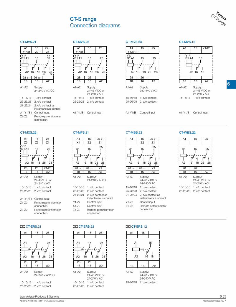
6
TimersCT Range
Low Voltage Products & Systems 6.85ABB Inc. • 888-385-1221 • www.abb.us/lowvoltage 1SXU000023C0202 Rev. A
CT-MVS.21 CT-MVS.22 CT-MVS.12
CT-MXS.22
A1
A1Y1/B1 15
A2 16 18
15Z2
18 16 A2
Y1/B1 Z125 21
28 24 26 22
2125
26 2822 24
A1
A1Y1/B1 15 25
A2 16 18 26 28
15
28 26
25
18 16 A2
Y1/B1A1
A1Y1/B1 15
A2 16 18
15 Y1/B1
18 16 A2
A1
A1Y1/B1 15 25
A2 16 18 26 28
15Z2
28 26 Y1/B1
25
18 16 A2
Z3 Z1
A1
A1Y1/B1 15 25
A2 16 18 26 28
15
28 26
25
18 16 A2
Y1/B1
CT-MVS.23
A1
A1 15 2125
A2 16 18 26 2822 24
15Z2
28 2624 22 Y1
Z1
18 16 A2
X125 21 A1
A1 15 2125
A2 16 18 26 2822 24
15Z2
28 2624 22 Y1
Z1
18 16 A2
25 21 A1
A1 15 25
A2 16 18 26 28
15
28 26
25
18 16 A2
CT-MFS.21 CT-MBS.22 CT-WBS.22
A CT-ERS.21
A1
A1 15
A2 16 18
15
18 1628 26
A2
25
25
26 28
A1
A1
A2 16 18
15
15
18 16 A2
A CT-ERS.22 A CT-ERS.12
A1
A1 15
A2 16 18
15
18 1628 26
A2
25
25
26 28
A1-A2 Supply: 24-240 V AC/DC
15-16/18 1. c/o contact25-26/28 2. c/o contact21-22/24 2. c/o contact as instantaneous contactA1-Y1/B1 Control inputZ1-Z2 Remote potentiometer connection
A1-A2 Supply: 24-48 V DC or 24-240 V AC15-16/18 1. c/o contact25-26/28 2. c/o contact
A1-Y1/B1 Control input
A1-A2 Supply: 24-48 V DC or 24-240 V AC15-16/18 1. c/o contact
A1-Y1/B1 Control input
A1-A2 Supply: 24-48 V DC or 24-240 V AC15-16/18 1. c/o contact25-26/28 2. c/o contact
A1-Y1/B1 Control inputZ1-Z2 Remote potentiometer connectionZ3-Z2 Remote potentiometer connection
A1-A2 Supply: 380-440 V AC
15-16/18 1. c/o contact25-26/28 2. c/o contact
A1-Y1/B1 Control input
A1-A2 Supply: 24-240 V AC/DC
15-16/18 1. c/o contact25-26/28 2. c/o contact21-22/24 2. c/o contact as instantaneous contactY1-Z2 Control inputX1-Z2 Control inputZ1-Z2 Remote potentiometer connection
A1-A2 Supply: 24-48 V DC or 24-240 V AC15-16/18 1. c/o contact25-26/28 2. c/o contact21-22/24 2. c/o contact as instantaneous contactY1-Z2 Control inputZ1-Z2 Remote potentiometer connection
A1-A2 Supply: 24-48 V DC or 24-240 V AC15-16/18 1. c/o contact25-26/28 2. c/o contact
A1-A2 Supply: 24-240 V AC/DC
15-16/18 1. c/o contact25-26/28 2. c/o contact
A1-A2 Supply: 24-48 V DC or 24-240 V AC15-16/18 1. c/o contact25-26/28 2. c/o contact
A1-A2 Supply: 24-48 V DC or 24-240 V AC15-16/18 1. c/o contact
CT-S rangeConnection diagrams

6
Timers
CT Range
6.86 Low Voltage Products & Systems
1SXU000023C0202 Rev. A ABB Inc. • 888-385-1221 • www.abb.us/lowvoltage
B CT-APS.21 B CT-APS.22 B CT-AHS.22
B CT-ARS.11
A1
Y1/B1 A1 15 25
A2 16 18 26 28
15Y1/B1
2628
25
18 16 A2
A1
A1 15 25
A2 16 18 26 28
15Z2
2628
25
18 16 A2Y1
15A1
A1
A2 16 18
15
18 16 A2
A1
Y1/B1 A1
A2 16 18
15
15 Y1/B1
18 16 A2
B CT-APS.12
A1
A1 15 25
A2 16 18 26 28
15
2628
25
18 16 A2
A1
A1
A2 2-
1+
1+ 2- A2
A1
A1
A2 2-
4
3
1+
3 4
1+ 2- A2
B CT-ARS.21 B CT-VBS.17 B CT-VBS.18
F CT-SDS.22
A1
A1
A2 18 28
17
17
18 28 A2
F CT-SDS.23
A1
Y1/B1 A1 15 25
A2 16 18 26 28
15Y1/B1
2628
25
18 16 A2
A1
A1
A2 18 28
17
17
18 28 A2
A1-A2 Supply: 24-240 V AC/DC
15-16/18 1. c/o contact25-26/28 2. c/o contact
A1-Y1/B1 Control input
A1-A2 Supply: 24-48 V DC or 24-240 V AC15-16/18 1. c/o contact25-26/28 2. c/o contact
A1-Y1/B1 Control input
A1-A2 Supply: 24-48 V DC or 24-240 V AC15-16/18 1. c/o contact25-26/28 2. c/o contact
Y1-Z2 Control input
A1-A2 Supply: 24-240 V AC/DC15-16/18 1. c/o contact
A1-A2 Supply: 24-48 V DC or 24-240 V AC15-16/18 1. c/o contact
A1-Y1/B1 Control input
A1-A2 Supply: 24-240 V AC/DC15-16/18 1. c/o contact25-26/28 2. c/o contact
A1-A2 Supply: 110-127 V AC1+ - 2- Contactor coil
A1-A2 Supply: 200-240 V AC1+ - 2- Contactor coil3-4 Jumper for setting the time delay (see time delay diagram)
A1-A2 Supply: 24-48 V DC or 24-240 V AC17-18 1. n/o contact17-28 2. n/o contact
A1-A2 Supply: 380-440 V AC
17-18 1. n/o contact17-28 2. n/o contact
CT-S rangeConnection diagrams
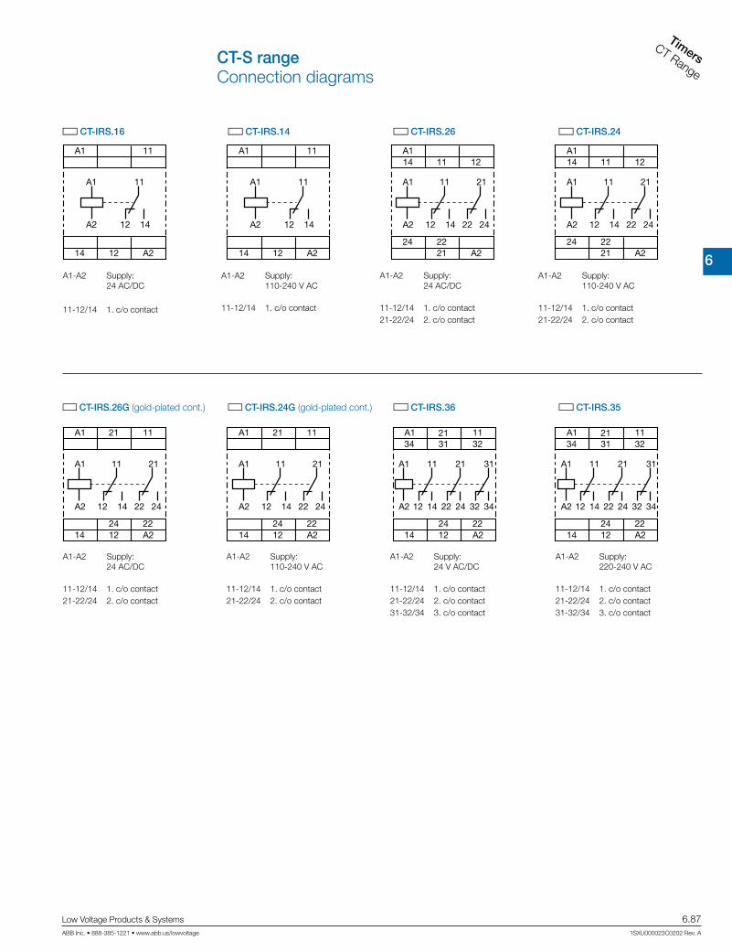
6
TimersCT Range
Low Voltage Products & Systems 6.87ABB Inc. • 888-385-1221 • www.abb.us/lowvoltage 1SXU000023C0202 Rev. A
CT-S rangeConnection diagrams
G CT-IRS.16 G CT-IRS.14 G CT-IRS.24
A1
A1 11
A2 12 14
14 12 A2
11
A1
A1
A2
21
21
22
22
24
24
A2
11
11
14
14
12
12
A1
A1
A2 12 14 22 24
11 21
212224
A2
1114 12
G CT-IRS.26
A1
A1
A2
21
22
22
24
24
A2
11
11 21 31
32
32
3134
34
14
14
12
12
G CT-IRS.36 G CT-IRS.35
A1
A1 11
A2 12 14
14 12 A2
11 A1
A1
A2 12 14 22 24
11 21
212224
A2
1114 12
A1
A1
A2
21
21
22
22
24
24
A2
11
11
14
14
12
12
A1
A1
A2
21
22
22
24
24
A2
11
11 21 31
32
32
3134
34
14
14
12
12
A1-A2 Supply: 24 AC/DC
11-12/14 1. c/o contact
A1-A2 Supply: 110-240 V AC
11-12/14 1. c/o contact
A1-A2 Supply: 110-240 V AC
11-12/14 1. c/o contact21-22/24 2. c/o contact
A1-A2 Supply: 24 AC/DC
11-12/14 1. c/o contact21-22/24 2. c/o contact
A1-A2 Supply: 24 AC/DC
11-12/14 1. c/o contact21-22/24 2. c/o contact
A1-A2 Supply: 110-240 V AC
11-12/14 1. c/o contact21-22/24 2. c/o contact
A1-A2 Supply: 24 V AC/DC
11-12/14 1. c/o contact21-22/24 2. c/o contact31-32/34 3. c/o contact
A1-A2 Supply: 220-240 V AC
11-12/14 1. c/o contact21-22/24 2. c/o contact31-32/34 3. c/o contact
G CT-IRS.26G (gold-plated cont.) G CT-IRS.24G (gold-plated cont.)

6
Timers
CT Range
6.88 Low Voltage Products & Systems
1SXU000023C0202 Rev. A ABB Inc. • 888-385-1221 • www.abb.us/lowvoltage
Data at Ta = 25 °C and rated values, unless otherwise indicated
CT-S
Input circuit - Supply circuit
Rated control supply voltage Us
CT-xxx.x1 24-240 V AC/DCCT-xxx.x2 24-48 V DC, 24-240 V ACCT-xxx.x3 380-440 V ACCT-xxx.x4 110-240 V ACCT-xxx.x5 220-240 V ACCT-xxx.x6 24 V AC/DCCT-xxx.x7 100-127 V AC or 110 V DCCT-xxx.x8 200-240V AC/DC
Rated control supply voltage US tolerance -15...+10 %Rated frequency DC or 50/60 HzFrequency range AC 47-63 HzTypical current / power consumption depending on device, see data sheet
Power failure buffering time24 V DC min. 15 ms
230/400 V AC min. 20 msInput circuit - Control circuit
Kind of triggering CT-MVS, CT-MXS, CT-APS voltage-related triggering
Control input, Control function A1-Y1 start timing external (CT-MVS, CT-MXS, CT-APS)
Parallel load / polarized yes / no
Maximum cable length to the control input 50 m - 100 pF/m
Minimum control pulse length 20 ms
Control voltage potential see rated control supply voltage
Current consumption of the control input 24 V DC 1.2 mA
230 V AC 8 mA
400 V AC 6 mA
Kind of triggering CT-MFS, CT-MBS, CT-AHS volt-free triggering
Control input, Control functionY1-Z2 start timing external (CT-MFS, CT-MBS, CT-AHS)
X1-Z2 pause timing / accumulative functions (CT-MFS)Maximum switching current in the control circuit 1 mAMaximum cable length to the control input 50 m - 100 pF/mMinimum control pulse length 20 msNo-load voltage at the control inputs 10-40 V DC
Remote potentiometer
Remote potentiometer connections, Resistance valueZ1-Z2 50 kΩ (CT-MFS, CT-MBS, CT-MVS.21, CT-MXS)
Z3-Z2 50 kΩ (CT-MXS)
Maximum cable length to remote potentiometer 2 x 25 m, shielded with 100 pF/m
Shield connection Z2
Timing circuit
Time ranges
10 time ranges 0.05 s - 300 h1.) 0.05-1 s 2.) 0.15-3 s 3.) 0.5-10 s 4.) 1.5-30 s 5.) 5-100 s
6.) 15-300 s 7.) 1.5-30 min 8.) 15-300 min 9.) 1.5-30 h 10.) 15-300 h
7 time ranges 0.05 s - 10 min (CT-SDS, CT-ARS)1.) 0.05-1 s 2.) 0.15-3 s 3.) 0.5-10 s
4.) 1.5-30 s 5.) 5-100 s 6.) 15-300 s 7.) 0.5-10 min
Recovery time
24-240 V AC/DC <50 ms
24-48 V DC, 24-240 V AC < 80 ms
380-440 V AC < 60 ms
Accuracy within the rated control supply voltage tolerance it < 0.004 % / V
Accuracy within the temperature range it < 0.03 % / °C
Repeat accuracy (constant parameters) it < 0.2 %
Star-delta transition time fixed 50 ms (CT-SDS, CT-MBS, CT-MFS, CT-MVS.2x)
Star-delta transition time tolerance ±2 ms
Minimum energizing time 100 ms (CT-ARS)
Formatting time 1) 5 min (CT-ARS)
1) prior to first commisioning and after a six-month stop in operation
CT-S rangeTechnical data

6
TimersCT Range
Low Voltage Products & Systems 6.89ABB Inc. • 888-385-1221 • www.abb.us/lowvoltage 1SXU000023C0202 Rev. A
CT-S rangeTechnical data
Indication of operational states
Control supply voltage / timing U/T: green LED V: control supply voltage applied / W: timing
Control supply voltage U: green LED V: control supply voltage applied
Relay state R, R1, R2: yellow LED V: output relay energized (R, R1, R2)
Output circuit
Kind of output
15-16/18 relay, 1 c/o contact
15-16/18; 25-26/28 relay, 2 c/o contacts
15-16/18; 25(21)-26(22)/28(24) relay, 2 c/o contacts, 2nd c/o contact selectable as inst. contact
17-18; 17-28 relay, 2 n/o contacts (CT-SDS)
Contact material Cd-free, on request
Rated operational voltage Ue IEC/EN 60947-1 250 V
Minimum switching voltage / minimum switching current 12 V / 10 mA (CT-IRS.2xG: 10 mV / 10 μA)
Maximum switching voltage / maximum switching current see load limit curves (CT-IRS.2xG: 10 V / 200 mA)
Rated operational current Ie (IEC/EN 60947-5-1 )
AC12 (resistive) at 230 V 4 A
AC15 (inductive) at 230 V 3 A
AC15 (inductive) at 230 V 4 A
DC13 (inductive) at 24 V 2 A (CT-ARS; 1.5 A)
AC rating (UL 508)
Utilization category (Control Circuit Rating Code) B 300
max. rated operational voltage 300 V AC
Maximum continuous thermal current at B300 5 A
max. making/breaking apparent power at B300 3600 VA / 360 VA
Mechanical lifetime 30 x 106 switching cycles
Electrical lifetime at AC12, 230 V, 4 A 0.1 x 10⁶ switching cycles
Max. fuse rating to achieve short-circuit protection (IEC/EN 60947-5-1)
n/c contact 6 A fast-acting
n/o contact 10 A fast-acting
General data 2)
MTBF on request
Duty time 100%
Dimensions (W x H x D)product dimensions 22.5 x 85.6 x 103.7 mm (0.89 x 3.37 x 4.08 in)
packaging dimensions 97 x 109 x 30 mm (3.82 x 4.29 x 1.18 in)
Weight depending on device, see ordering details
Mounting DIN rail (IEC/EN 60715), snap-on mounting without any tool
Mounting position any
Minimum distance to other units vertical / horizontal not necessary / not necessary
Material of housing UL 94 V-0
Degree of protection housing / terminals IP50 / IP20
Electrical connection 2)
Screw connection technologyEasy Connect Technology
(Push-in)
Wire size
fine-strand with(out) wire end ferrule1 x 0.5-2.5 mm2 (1 x 20-14 AWG)
2 x 0.5-1.5 mm2 (2 x 20-16 AWG)2 x 0.5-1.5 mm2 (2 x 20-16 AWG)
rigid1 x 0.5-4 mm2 (1 x 20-12 AWG)
2 x 0.5-2.5 mm2 (2 x 20-14 AWG)2 x 0.5-1.5 mm2 (2 x 20-16 AWG)
Stripping length 8 mm (0.32 in)
Tightening torque 0.6-0.8 Nm (5.31-7.08 lb.in) -
2) Data for all references 1SVR 730 xxx xxx and 1SVR 740 xxx xxx. For devices with 1SVR 430 xxx xxx and 1SVR 630 xxx xxx please refer to the data sheet.

6
Timers
CT Range
6.90 Low Voltage Products & Systems
1SXU000023C0202 Rev. A ABB Inc. • 888-385-1221 • www.abb.us/lowvoltage
Environmental data
Ambient temperature ranges operation / storage
-25...+60 °C / -40...+85 °C,
-40...+60 °C / -40...+85 °C (CT-MVS.21,
CT-MFS.21, CT-ERS.21, CT-APS.21)Damp heat (cyclic) (IEC/EN 60068-2-30) 6 x 24 h cycle, 55 °C, 95 % RH
Vibration, sinusoidal (IEC/EN 60068-2-6)functioning 40 m/s2, 10-58/60-150 Hzresistance 60 m/s2, 10-58/60-150 Hz, 20 cycles
Vibration, seismic (IEC/EN 60068-3-3) functioning 20 m/s2
Shock, half-sine (IEC/EN 60068-2-27)functioning 100 m/s2, 11 ms, 3 shocks/directionresistance 300 m/s2 , 11 ms, 3 shocks/direction
Isolation dataRated insulation voltage Ui input circuit / output circuit 500 VRated impulse withstand voltage Uimpbetween all isolated circuits VDE 0110, IEC/EN 60664 4 kV; 1.2/50 μs
Power-frequency withstand voltage test betweenall isolated circuits (test voltage)
routine test 2.0 kV, 50Hz, 1 stype test 2.5 kV, 50 Hz, 1 min
Basic insulation (IEC/EN 61140) input circuit / output c ircuit 500 VProtective separation (IEC/EN 61140; IEC/EN 50178; VDE 0106 part 101 and part 101/ A1)
input circuit / output circuit 250 V
Pollution degree (IEC/EN 60664-1, VDE 0110) 3Overvoltage category (IEC/EN 60664-1, VDE 110) IIIStandardsProduct standard IEC 61812-1, EN 61812-1 + A11, DIN VDE 0435 part 2021Low Voltage Directive 2006/95/ECEMC Directive 2004/108/ECRoHS Directive 2002/95/ECElectromagnetic compatibilityInterference immunity to IEC/EN 61000-6-1, IEC/EN 61000-6-2
electronic discharge IEC/EN 61000-6-2 Level 3 6 kV / 8 kVradiated, radio-frequencyelectromagnetic field IEC/EN 61000-6-3 Level 3 10 V/m (1 GHz) 3 V/m (2 GHz) 1 V/m (2.7 GHz)
electrical fast transient/burst IEC/EN 61000-6-4 Level 3 2 kV / 5 kHzsurge IEC/EN 61000-6-5 Level 4 2 kV A1-A2conducted disturbances, induced by radio-frequency fields IEC/EN 61000-6-6 Level 3 10 V
Level 3
Interference emissions IEC/EN 61000-6-3, IEC/EN 61000-6-4high-frequency radiated IEC/CISPR 22, EN 55022 Class Bhigh-frequency conducted IEC/CISPR 22, EN 55022 Class B
CT-S rangeTechnical data

6
TimersCT Range
Low Voltage Products & Systems 6.91ABB Inc. • 888-385-1221 • www.abb.us/lowvoltage 1SXU000023C0202 Rev. A
CT-S rangeTechnical diagrams
AC load (resistive) DC load (resistive)
Technical diagramsLoad limit curves
Derating factor F for inductive AC load
Contact lifetime
DC current [A]
resistive load
DC
vol
tage
[V]
cos j
0.5
0.1 0.2 0.3 0.4 0.5 0.6 0.7 0.8 0.9 1.0
0.6
0.7
0.8
0.9
1.0
Der
atin
g fa
ctor
F
AC current [A]
resistive loadAC
vol
tage
[V]
Switching current [A]
250 Vresistive load
Sw
itchi
ng c
ycle
s

6
Timers
CT Range
6.92 Low Voltage Products & Systems
1SXU000023C0202 Rev. A ABB Inc. • 888-385-1221 • www.abb.us/lowvoltage
100
102
109,5 4.31“ 22,5
.886“
783.
07“
4.02“
3.94“
L(+)
N(-)
A1 Y1
Z2
X1
A2
L(+)
N(-)
A1 Y1/B1
A2
L(+) L(+)
N(-) L(-)
A1 Y1/B1
A2
L(+)
N(-)
A1 Z1
Z2
Z3
A2
L(+) +V
N(-) 0 V
A1 Y1
Z2A2
Dimensional drawing Dimensions in mm and inches
Wiring notes
Remote potentiometer
Control inputs (volt-free triggering)
Control inputs (voltage-related triggering)
Triggering of the control inputs (volt-free) with a proximity switch (3 wire)
The control input Y1/B1 is triggered with electric potential against A2. It is possible to use the control supply voltage from terminal A1 or any other voltage within the rated control supply voltage range.
113.4 4.47”
22.5 0.89”
85.6
3.
37”
103.7 4.08”
105.9 4.17”
1SVR 430 xxx xxx, 1SVR 630 xxx xxx 1SVR 730 xxx xxx, 1SVR 740 xxx xxx
CT-S rangeWiring notesApproximate dimensions

6
Measuring &
monitoring relays
CM Range
Low Voltage Products & Systems 6.93ABB Inc. • 888-385-1221 • www.abb.us/lowvoltage 1SXU000023C0202 Rev. A
CM-E Range
Mea
surin
g &
mon
itorin
g re
lays
CM
-E R
ange

6
Measuring &
monitorin
g relays
CM Range
6.94 Low Voltage Products & Systems
1SXU000023C0202 Rev. A ABB Inc. • 888-385-1221 • www.abb.us/lowvoltage
• Only 22.5 mm wide housing• Output contacts: 1 c/o contact or 1 n/o contact• One supply voltage range• One monitoring function• Cost-efficient solution for OEM applications• Preset monitoring ranges
Combination screws 1
Easy tightening and release of the connecting screws with pozidrive, pan- or crosshead screwdriver.
Safety 2
The "real distance" is hidden. The clearance and the creepage distances of our products exceed international standards and substantially increase the safety of our products.
• Only 22.5 mm wide housing• Output contacts: 1 or 2 c/o (SPDT) contacts• One supply voltage range or supplied by measuring circuit• Setting and operation via front-face operating controls• Adjustment of threshold values and switching hysteresis via
direct reading scale• Integrated and snap-fitted front-face marker• Snap-on housing: The relays can be placed on a DIN rail tool-free - just
snap it on or remove it tool-free• Sealable transparent cover (accessory)
CM-S range: Universal and multifunctional Benefits CM-E range
1 3
4
5 7
6 82
Measuring and monitoring relaysBenefits and advantages.

6
Measuring &
monitoring relays
CM Range
Low Voltage Products & Systems 6.95ABB Inc. • 888-385-1221 • www.abb.us/lowvoltage 1SXU000023C0202 Rev. A
• 45 mm wide housing• Output contacts: 2 c/o (SPDT) contacts• Continuous voltage range (24-240 V AC/DC) or single-supply• Setting and operation via front-face operating controls• Adjustment of threshold values and switching hysteresis via
direct reading scale• Adjustable time delays• Integrated and snap-fitted front-face marker label• Sealable transparent cover (accessory)
Easy Connect Technology & Double-chamber cage connection terminals
CM-N range: Multifunctional
Benefits new CM-S range housing
Easy Connect Technology 3
Tool-free wiring for excellent vibration resistance. Push-in terminals provide connection of wires up to 2 x 0.5 - 1.5 mm², rigid or fine stranded with or without wire end ferrules.
Double-chamber cage connection terminals 4
Double-chamber cage connection terminals provide connection of wires up to 2 x 0.5-2.5 mm² (2 x 20-14 AWG) rigid or fine-strand, with or without wire end ferrules. Potential distribution does not require additional termi-nals.
Snap-On housing 8
Tool-free DIN rail installation and deinstallation of the monitoring relay with Snap-On housing.
LED‘s for status indication 5
All actual operational states are displayed by front-face LED‘s, thus simpli-fying commissioning and troubleshooting.
Integrated marker label 6
Integrated marker labels allow the product to be marked quickly and sim-ply. No additional marker labels are required.
Sealable transparent cover 7
Protection against unauthorized changes of time and threshold values. Available as an accessory.ABBs measuring and monitoring relays in a new housing
Benefits at a glance
Double-chamber cage connection terminals
Easy conversions:The old range of measuring and monitoring relays is replaced by an identical range of relays with Double-chamber cage connection terminals. The ordering number just changed in one digit:
1SVRx3 … changed to 1SVR73...1SVRx5 … changed to 1SVR75...
and for the type designator we are using one more specifier:CM-xxS changed to CM-xxS.SCM-xxN changed to CM-xxN.SThe new range is identically replacing the old range.
Ratings:Double-chamber cage connection terminals provide connection of wires up to 1 x 0.5-4 mm² (1 x 20-12 AWG) or 2 x 0.5-2.5 mm² (2 x 20-14 AWG) rigid or 1 x 0.5-2.5 mm² (1 x 20-14 AWG) / 2 x 0.5-1.5 mm² (2 x 20 -16 AWG), rigid or fine-strand,with or without wire end ferrules. Potential distri-bution does not require additional terminals.
Extended features
Flammability:The plastic housing material used meets the requirements for the highest flammability class. (UL94 V-O rated)
Look and feel:
The new housing fits perfectly with ABB’s control products offer.
Easy Connect Technology
New options:Additionally to the existing well established screw connections a new innovative connection technology can be offered: Easy Connect Technology with push-in terminals.
Tool-free Wiring:The push-in terminals can be wired with rigid or fine stranded wires with wire end ferrules totally tool-free. The connection direction is exactly the same as the screw version.
Higher utility class:The Easy Connect Technology provides excellent vibration resistance with gas tight push-in terminals – the right solution forharsh environment.
Ratings:Push-in terminals provide connection of wires up to 2 x 1.5mm² (2 x 20-16 AWG), rigid or fine stranded with or without wire end ferrules.
Measuring and monitoring relaysBenefits and advantages.

6
Measuring &
monitorin
g relays
CM Range
6.96 Low Voltage Products & Systems
1SXU000023C0202 Rev. A ABB Inc. • 888-385-1221 • www.abb.us/lowvoltage
Single-phase current and voltage monitoring Three-phase monitoring Phase loss CM-PBE Over- and undervoltage CM-PVE Phase sequence and phase loss CM-PFE and CM-PFS Phase sequence and phase loss, over- and undervoltage
CM-PSS.xx and CM-PVS.xx Phase sequence and phase loss, unbalance CM-PAS.xx Phase sequence and phase loss, unbalance, over- and undervoltage
CM-MPS.xx and CM-MPN.xx Over- and undervoltage, over- and underfrequency CM-UFS.x
Motor load monitoringCM-LWN monitoring relays load states of single- and three-phase asynchronous motors.
Current monitoring
Monitoring of motor current consumption Monitoring of lighting installations and heating circuits Monitoring of hoisting gear and transportation equipment overload Monitoring of locking devices, electromechanical brake gear and locked rotor
Voltage monitoring
Speed monitoring of DC motors Monitoring of battery voltages and other supply networks Monitoring of upper and lower voltage threshold values
CM-IWS.2 for electrically isolated AC systems, and CM-IWS.1 & CM-IWN 1 for electrically isolated AC, DC and mixed AC/DC systems.
CM-IWN.5 for solar applications ≤ 1000 μF
Three-phase voltage monitoring
Voltage monitoring of mobile three-phase equipment Protection of personnel and installations against phase reversal Monitoring of the supply voltage to machines and installations Protection of equipment against damage caused by unstable supply
voltage Switching to emergency or auxiliary supply Protection of motors against damage caused by unbalanced phase volt-
ages and phase loss Automatic connection & disconnection of decentralised power stations to the grid
Insulation monitoring
Insulation monitoring
Monitoring of electrically isolated supply mains for insulation resistance failure Detection of initial faults Protection against earth faults
Motor load monitoring
Detection of V-belt breaking Motor protection against overload Monitoring of filters for clogging Protection of pumps against dry running Detection of high pressure in conduit systems Monitoring for dulling blades in sawing and cutting machines
Over- or undercurrent monitoring CM-SRS and CM-SRS.M Over- and undercurrent monitoring CM-SFS Over- or undervoltage monitoring CM-ESS and CM-ESS.M Over- and undervoltage monitoring CM-EFS
ϑ
Thermistor motor protectionCM-MSE, CM-MSS and CM-MSN provide full protection of motors with integrated PTC resistor sensors.
Thermistor motor protection
Protection of motors against thermal overload, e. g. caused by insuf-ficient cooling, heavy load starting conditions, undersized motors, etc.
CM-ENE, CM-ENS and CM-ENN for control and regulation of liquid levels and ratios of mixtures of conductive fluids.
Liquid level monitoring and control
Protection of pumps against dry running Protection against container overflow Control of liquid levels Detection of leaks Control of mixing ratios
Liquid level monitoring
Measuring and monitoring relaysMonitoring features and application ranges

6
Measuring &
monitoring relays
CM Range
Low Voltage Products & Systems 6.97ABB Inc. • 888-385-1221 • www.abb.us/lowvoltage 1SXU000023C0202 Rev. A
Liquid level monitoring and control
Protection of pumps against dry running Protection against container overflow Control of liquid levels Detection of leaks Control of mixing ratios
ϑ
The CM-KRN protects sensitive control contacts from excessive loads and can store switch positions. The CM-SIS supplies and evaluates NPN and PNP sensors.
Contact protection, sensor evaluation
Temperature monitoring
Cycle monitoring
Contact protection / sensor evaluation
Storage of the switching states of bouncing contacts Amplification of the switch state information of sensitive contacts Supply and evaluation of NPN or PNP sensors
Cycle monitoring
External monitoring of the correct function of programmable logic controllers (plc) and industrial pcs (ipc)
Temperature monitoring
Motor and system protection Control panel temperature monitoring Frost monitoring Temperature limits for process variables, e.g. in the packing or electroplating industry Control of systems and machines like heating, air-conditioning and ventilation systems, solar collectors, heat pumps or hot water supply systems Monitoring of servomotors with KTY sensors Bearing and gear oil monitoring Coolant monitoring
Acquisition, messaging and regulation of temperatures of solid, liquid and gaseous media in processes and machines via PT100, PT1000, KTY83, KTY 84 or NTC sensors with C510, C511, C512, C513.
Measuring and monitoring relaysMonitoring features and application ranges
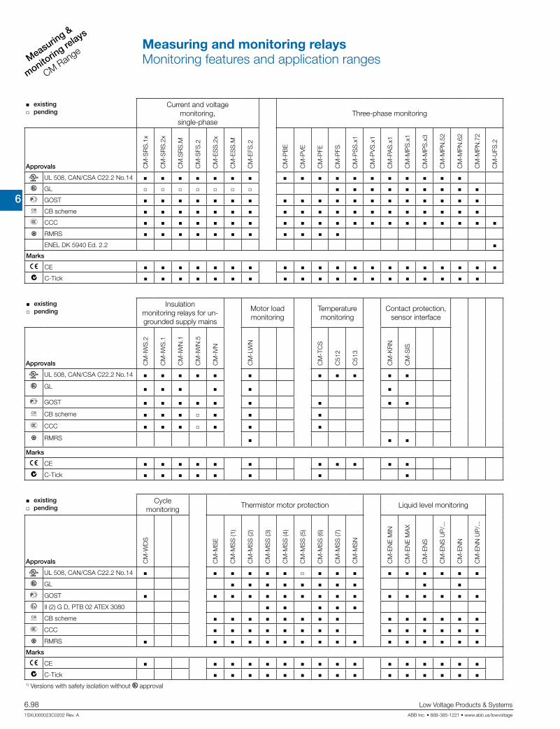
6
Measuring &
monitorin
g relays
CM Range
6.98 Low Voltage Products & Systems
1SXU000023C0202 Rev. A ABB Inc. • 888-385-1221 • www.abb.us/lowvoltage
existing j pending
Current and voltage monitoring,
single-phaseThree-phase monitoring
Approvals CM
-SR
S.1
x
CM
-SR
S.2
x
CM
.SR
S.M
CM
-SFS
.2
CM
-ES
S.2
x
CM
-ES
S.M
CM
-EFS
.2
CM
-PB
E
CM
-PV
E
CM
-PFE
CM
-PFS
CM
-PS
S.x
1
CM
-PV
S.x
1
CM
-PA
S.x
1
CM
-MP
S.x
1
CM
-MP
S.x
3
CM
-MP
N.5
2
CM
-MP
N.6
2
CM
-MP
N.7
2
CM
-UFS
.2
A UL 508, CAN/CSA C22.2 No.14
C GL j j j j j j j
D GOST
K CB scheme
E CCC
L RMRS
ENEL DK 5940 Ed. 2.2
Marks
a CE
b C-Tick
existing j pending
Insulation monitoring relays for un-grounded supply mains
Motor load monitoring
Temperature monitoring
Contact protection, sensor interface
Approvals CM
-IW
S.2
CM
-IW
S.1
CM
-IW
N.1
CM
-IW
N.5
CM
-IV
N
CM
-LW
N
CM
-TC
S
C51
2
C51
3
CM
-KR
N
CM
-SIS
A UL 508, CAN/CSA C22.2 No.14
C GL
D GOST
K CB scheme j
E CCC j
L RMRS
Marks
a CE
b C-Tick
existing j pending
Cycle monitoring
Thermistor motor protection Liquid level monitoring
Approvals CM
-WD
S
CM
-MS
E
CM
-MS
S (1
)
CM
-MS
S (2
)
CM
-MS
S (3
)
CM
-MS
S (4
)
CM
-MS
S (5
)
CM
-MS
S (6
)
CM
-MS
S (7
)
CM
-MS
N
CM
-EN
E M
IN
CM
-EN
E M
AX
CM
-EN
S
CM
-EN
S U
P/.
..
CM
-EN
N
CM
-EN
N U
P/.
..
A UL 508, CAN/CSA C22.2 No.14 j
C GL
D GOST
I II (2) G D, PTB 02 ATEX 3080
K CB scheme
E CCC
L RMRS
Marks
a CE
b C-Tick 1) Versions with safety isolation without C approval
Measuring and monitoring relaysMonitoring features and application ranges

6
Measuring &
monitoring relays
CM Range
Low Voltage Products & Systems 6.99ABB Inc. • 888-385-1221 • www.abb.us/lowvoltage 1SXU000023C0202 Rev. A
Current & voltage monitoring relaysSingle phase
Cur
rent
& v
olta
ge m
onito
ring
rela
ysC
M-E
Ran
ge

6
Measuring &
monitorin
g relays
CM Range
6.100 Low Voltage Products & Systems
1SXU000023C0202 Rev. A ABB Inc. • 888-385-1221 • www.abb.us/lowvoltage
Characteristics current monitoring relays
Monitoring of DC and AC currents: 3 mA to15 A 1)
TRMS measuring principle One device includes 3 measuring ranges Over- and undercurrent monitoring1)
ON or OFF delay configurable1)
Open- or closed circuit principle configurable1)
Latching function configurable1)
Thresholds for >I and/or <I adjustable1)
Fixed hysteresis of 5 %1)
Start-up delay Tv adjustable 0; 0.1 - 30 s1)
Tripping delay Tv adjustable 0; 0.1 - 30 s1)
1 x 2 c/o contacts (common signal) or 2 x 1 c/o contact (separate signals for >I and <I) configurable1)
22.5 mm width 3 LED's for status indication
1) depending on device
Characteristics voltage monitoring relays
Monitoring of DC and AC voltages from 3 - 600 V TRMS measuring principle One device includes 4 measuring ranges: 3 - 30 V; 6 - 60 V;
30 - 300 V; 60 - 600 V Over- and undervoltage monitoring1)
ON or OFF delay configurable1)
Open- or closed circuit principle configurable1)
Latching function configurable1)
Threshold values for >U and/or <U adjustable1)
Fixed hysteresis of 5 %1)
Start-up delay Tv adjustable 0; 0.1 - 30 s1)
Tripping delay Tv adjustable 0; 0.1 - 30 s1)
1 x 2 c/o contacts (common signal) or 2 x 1 c/o contact (separate signals for >U and <U) configurable1)
22.5 mm width 3 LED's for status indication
Current monitoring, single-phase
The ABB current monitoring relays CM-SRS.xx reliably monitor the occurence of currents that exceed or fall below the selected threshold value. The functions overcurrent or undercurrent monitoring can be pre-selected. Single- and multifunction devices for the monitoring of direct or alternating currents from 3 mA to 15 A are available.
Voltage monitoring, single-phase
The ABB voltage monitoring relays CM-SRS.xx are used to monitor direct and alternating voltages within a range of 3-600 V. Over- or undervoltage detection can be preselected.
Current window monitoring (Imin, Imax)
The window monitoring relay CM-SFS.2x is available if the application re-quires the simultaneous monitoring of over-and undercurrents.
Voltage window monitoring (Umin, Umax)
For the simultaneous detection of over- and undervoltages, the window monitoring relay CM-EFS.2 can be used.
Current and voltage monitoring relays, single phaseBenefits and advantages

6
Measuring &
monitoring relays
CM Range
Low Voltage Products & Systems 6.101ABB Inc. • 888-385-1221 • www.abb.us/lowvoltage 1SXU000023C0202 Rev. A
Pre
dec
esso
r
1SV
R43
0840
R02
00
1SV
R43
0841
R02
00
1SV
R43
0841
R12
00
1SV
R43
0840
R03
00
1SV
R43
0841
R03
00
1SV
R43
0841
R13
00
1SV
R43
0840
R04
00
1SV
R43
0841
R04
00
1SV
R43
0841
R14
00
1SV
R43
0840
R05
00
1SV
R43
0841
R05
00
1SV
R43
0841
R15
00
1SV
R43
0840
R06
00
1SV
R43
0840
R07
00
1SV
R43
0760
R04
00
1SV
R43
0760
R05
00
Cat
alo
g n
um
ber
1SV
R73
0840
R02
00
1SV
R74
0840
R02
00
1SV
R73
0841
R02
00
1SV
R74
0841
R02
00
1SV
R73
0841
R12
00
1SV
R74
0841
R12
00
1SV
R73
0840
R03
00
1SV
R73
0841
R03
00
1SV
R73
0841
R13
00
1SV
R73
0840
R04
00
1SV
R74
0840
R04
00
1SV
R73
0841
R04
00
1SV
R74
0841
R04
00
1SV
R73
0841
R14
00
1SV
R74
0841
R14
00
1SV
R73
0840
R05
00
1SV
R73
0841
R05
00
1SV
R73
0841
R15
00
1SV
R73
0840
R06
00
1SV
R74
0840
R06
00
1SV
R73
0840
R07
00
1SV
R73
0760
R04
00
1SV
R74
0760
R04
00
1SV
R73
0760
R05
00
Ref
eren
ce c
ode
CM
-SR
S.1
1S
CM
-SR
S.1
1P
CM
-SR
S.1
1S
CM
-SR
S.1
1P
CM
-SR
S.1
1S
CM
-SR
S.1
1P
CM
-SR
S.1
2S
CM
-SR
S.2
1S
CM
-SR
S.2
1P
CM
-SR
S.2
1S
CM
-SR
S.2
1P
CM
-SR
S.2
1S
CM
-SR
S.2
1P
CM
-SR
S.2
2S
CM
-SR
S.M
1S
CM
-SR
S.M
1P
CM
-SR
S.M
2S
CM
-SFS
.21S
CM
-SFS
.21P
CM
-SFS
.22S
Rated control supply voltage Us
24 - 240 V AC/DC 110 - 130 V AC 220 - 240 V AC Measuring ranges AC/DC
3 - 30 mA 10 - 100 mA 0.1 - 1 A 0.3 - 1.5 A 1 - 5 A 3 - 15 A Monitoring function
Over- or undercurrent Windows current monitoring Latching sel sel sel sel sel sel
Open circuit or closed circuit principle sel sel sel sel sel sel
Timing functions for tripping delay
ON delay, 0 or 0,1 - 30 s adj adj adj adj adj adj adj adj adj adj adj adj
ON or OFF delay sel sel sel
Output
c/o contact 1 1 1 1 1 1 1 1 1 1 1 1 1 1 1 1 1 1 2 2 2 2 2 2
Connection type
Easy Connect Technology Double-chamber cage connection terminals
Current and voltage monitoring relays, single phaseSelection and conversion

6
Measuring &
monitorin
g relays
CM Range
6.102 Low Voltage Products & Systems
1SXU000023C0202 Rev. A ABB Inc. • 888-385-1221 • www.abb.us/lowvoltage
Pre
dec
esso
r
1SV
R43
0831
R03
00
1SV
R43
0831
R03
00
1SV
R43
0831
R13
00
1SV
R43
0830
R04
00
1SV
R43
0831
R04
00
1SV
R43
0831
R14
00
1SV
R43
0830
R05
00
1SV
R43
0750
R04
00
Cat
alo
g n
um
ber
1SV
R73
0831
R03
00
1SV
R74
0831
R03
00
1SV
R73
0831
R03
00
1SV
R74
0831
R03
00
1SV
R73
0831
R13
00
1SV
R74
0831
R13
00
1SV
R73
0830
R04
00
1SV
R74
0830
R04
00
1SV
R73
0831
R04
00
1SV
R74
0831
R04
00
1SV
R73
0831
R14
00
1SV
R74
0831
R14
00
1SV
R73
0830
R05
00
1SV
R74
0830
R05
00
1SV
R73
0750
R04
00
1SV
R74
0750
R04
00
Ref
eren
ce c
ode
CM
-ES
S.1
S
CM
-ES
S.1
P
CM
-ES
S.1
S
CM
-ES
S.1
P
CM
-ES
S.1
S
CM
-ES
S.1
P
CM
-ES
S.2
S
CM
-ES
S.2
P
CM
-ES
S.2
S
CM
-ES
S.2
P
CM
-ES
S.2
S
CM
-ES
S.2
P
CM
-ES
S.M
S
CM
-ES
S.M
P
CM
-EFS
.2S
CM
-EFS
.2P
Rated control supply voltage Us
24 - 240 V AC/DC 110 - 130 V AC 220 - 240 V AC Measuring ranges AC/DC
3 - 30 V 6 - 60 V 30 - 300 V 60 - 600 V Monitoring function
Over- or undervoltage Windows voltage monitoring Latching sel sel sel sel
Open circuit or closed circuit principle sel sel sel sel
Timing functions for tripping delay
ON delay, 0 or 0,1 - 30 s adj adj adj adj adj adj adj adj
ON or OFF delay sel sel
Output
c/o contact 1 1 1 1 1 1 2 2 2 2 2 2 2 2 2 2
Connection type
Easy Connect Technology Double-chamber cage connection terminals
Current and voltage monitoring relays, single phaseSelection and conversion

6
Measuring &
monitoring relays
CM Range
Low Voltage Products & Systems 6.103ABB Inc. • 888-385-1221 • www.abb.us/lowvoltage 1SXU000023C0202 Rev. A
Description
Single phase voltage and current monitors protect sensitive equipment and control systems against undervoltage, undercurrent events, overvoltage or overcurrent events. Different units with adjustable or fixed threshold values (trip points) are available.
Ordering details
Rated control supply voltage
Tripping delay TV Measuring rangeReference
codeCatalognumber
Weight (1 pce)
kg (lb)
24-240 V AC/DC
without3-30 mA
10-100 mA 0.1-1 A
CM-SRS.11S
1SVR730840R0200 0.145 (0.320)
110-130 V AC 1SVR730841R0200 0.161 (0.355)
220-240 V AC 1SVR730841R1200 0.161 (0.355)
24-240 V AC/DC
CM-SRS.11P
1SVR740840R0200 0.137 (0.302)
110-130 V AC 1SVR740841R0200 0.153 (0.337)
220-240 V AC 1SVR740841R1200 0.153 (0.337)
24-240 V AC/DC
without0.3-1.5 A
1-5 A 3-15 A
CM-SRS.12S
1SVR730840R0300 0.137 (0.302)
110-130 V AC 1SVR730841R0300 0.168 (0.370)
220-240 V AC 1SVR730841R1300 0.168 (0.370)
24-240 V AC/DC
adjustable 0 or 0.1-30 s
3-30 mA 10-100 mA
0.1-1 A
CM-SRS.21S
1SVR730840R0400 0.152 (0.335)
110-130 V AC 1SVR730841R0400 0.179 (0.395)
220-240 V AC 1SVR730841R1400 0.179 (0.395)
24-240 V AC/DC
CM-SRS.21P
1SVR740840R0400 0.141 (0.311)
110-130 V AC 1SVR740841R0400 0.168 (0.370)
220-240 V AC 1SVR740841R1400 0.168 (0.370)
24-240 V AC/DC
adjustable 0 or 0.1-30 s
0.3-1.5 A 1-5 A 3-15 A
CM-SRS.22S
1SVR730840R0500 0.144 (0.399)
110-130 V AC 1SVR730841R0500 0.181 (0.399)
220-240 V AC 1SVR730841R1500 0.181 (0.399)
24-240 V AC/DC adjustable 0 or 0.1-30 s
3-30 mA 10-100 mA
0.1-1 A
CM-SRS.M1S 1SVR730840R0600 0.153 (0.337)
CM-SRS.M1P 1SVR740840R0600 0.142 (0.313)
24-240 V AC/DC adjustable 0 or 0.1-30 s
0.3-1.5 A 1-5 A 3-15 A
CM-SRS.M2S 1SVR730840R0700 0.155 (0.342)
24-240 V AC/DC adjustable 0 or 0.1-30 s
3-30 mA 10-100 mA
0.1-1 A
CM-SFS.21S 1SVR730760R0400 0.150 (0.331)
CM-SFS.21P 1SVR740760R0400 0.139 (0.306)
24-240 V AC/DC adjustable 0 or 0.1-30 s
0.3-1.5 A 1-5 A 3-15 A
CM-SFS.22S 1SVR730760R0500 0.158 (0.348)
CM-SRS.22S
CM-SFS.22P
Current and voltage monitoring relays, single phaseOrdering detailsCurrent monitors

6
Measuring &
monitorin
g relays
CM Range
6.104 Low Voltage Products & Systems
1SXU000023C0202 Rev. A ABB Inc. • 888-385-1221 • www.abb.us/lowvoltage
Ordering details
Rated control supply voltage
Tripping delay TV Measuring rangeReference
codeCatalognumber
Weight (1 pce)
kg (lb)
24-240 V AC/DC
without
3-30 V 6-60 V
30-300 V 60-600 V
CM-ESS.1S
1SVR730830R0300 0.135 (0.298)
110-130 V AC 1SVR730831R0300 0.164 (0.362)
220-240 V AC 1SVR730831R1300 0.164 (0.362)
24-240 V AC/DC
CM-ESS.1P
1SVR740830R0300 0.126 (0.278)
110-130 V AC 1SVR740831R0300 0.155 (0.342)
220-240 V AC 1SVR740831R1300 0.155 (0.342)
24-240 V AC/DC
adjustable 0 or 0.1-30 s
3-30 V 6-60 V
30-300 V 60-600 V
CM-ESS.2S
1SVR730830R0400 0.153 (0.337)
110-130 V AC 1SVR730831R0400 0.181 (0.399)
220-240 V AC 1SVR730831R1400 0.181 (0.399)
24-240 V AC/DC
CM-ESS.2P
1SVR740830R0400 0.142 (0.313)
110-130 V AC 1SVR740831R0400 0.170 (0.375)
220-240 V AC 1SVR740831R1400 0.170 (0.375)
24-240 V AC/DC adjustable 0 or 0.1-30 s
3-30 V 6-60 V
30-300 V 60-600 V
CM-ESS.MS 1SVR730830R0500 0.154 (0.340)
CM-ESS.MP 1SVR740830R0500 0.143 (0.320)
24-240 V AC/DC adjustable 0 or 0.1-30 s
3-30 V 6-60 V
30-300 V 60-600 V
CM-EFS.2S 1SVR730750R0400 0.157 (0.346)
CM-EFS.2P 1SVR740750R0400 0.146 (0.322)
CM-ESS.MP
CM-EFS.2
Current and voltage monitoring relays, single phaseOrdering details,Voltage monitors
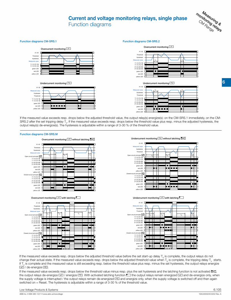
6
Measuring &
monitoring relays
CM Range
Low Voltage Products & Systems 6.105ABB Inc. • 888-385-1221 • www.abb.us/lowvoltage 1SXU000023C0202 Rev. A
Function diagrams CM-SRS.1
Overcurrent monitoring b
Undercurrent monitoring a
Function diagrams CM-SRS.2
Overcurrent monitoring b
Undercurrent monitoring a
A1-A2
11-14 (15-18)11-12 (15-16)
Threshold
Hysteresis
Measured value
green LED
red LED
yellow LED
A1-A2
11-14 (15-18)11-12 (15-16)
Threshold
Hysteresis
Measured value
green LED
red LED
yellow LED
A1-A2
11-14 (15-18)11-12 (15-16)
21-24 (25-28)21-22 (25-26)
Threshold
Hysteresis
Measured value
green LED
red LED
yellow LED
TV < TV
A1-A2
11-14 (15-18)11-12 (15-16)
21-24 (25-28)21-22 (25-26)
Threshold
Hysteresis
Measured value
green LED
red LED
yellow LED
TV < TV
Function diagrams CM-SRS.M
Overcurrent monitoring b without latching e
Overcurrent monitoring b with latching f
Undercurrent monitoring a without latching e
Undercurrent monitoring b with latching f
A1-A2
11-14 (15-18)11-12 (15-16)
21-24 (25-28)21-22 (25-26)
11-14 (15-18)11-12 (15-16)
21-24 (25-28)21-22 (25-26)
closed
open
Threshold
Hysteresis
Measured value
green LED
red LED
yellow LED
TS
green LED
red LED
yellow LED
Open-circuit principle
Closed-circuit principle
TV< TV
A1-A2
11-14 (15-18)11-12 (15-16)
21-24 (25-28)21-22 (25-26)
11-14 (15-18)11-12 (15-16)
21-24 (25-28)21-22 (25-26)
open
closed
Threshold
Hysteresis
Measured value
green LED
red LED
yellow LED
TS
green LED
red LED
yellow LED
Open-circuit principle
Closed-circuit principle
TV< TVTS
Reset
A1-A2
11-14 (15-18)11-12 (15-16)
21-24 (25-28)21-22 (25-26)
11-14 (15-18)11-12 (15-16)
21-24 (25-28)21-22 (25-26)
closed
open
Threshold
Hysteresis
Measured value
green LED
red LED
yellow LED
TS
green LED
red LED
yellow LED
Open-circuit principle
Closed-circuit principle
TV < TV
A1-A2
11-14 (15-18)11-12 (15-16)
21-24 (25-28)21-22 (25-26)
11-14 (15-18)11-12 (15-16)
21-24 (25-28)21-22 (25-26)
closed
open
Threshold
Hysteresis
Measured value
green LED
red LED
yellow LED
TS
green LED
red LED
yellow LED
Open-circuit principle
Closed-circuit principle
TV < TVTS
Reset
If the measured value exceeds resp. drops below the adjusted threshold value, the output relay(s) energize(s): on the CM-SRS.1 immediately, on the CM-SRS.2 after the set tripping delay TV. If the measured value exceeds resp. drops below the threshold value plus resp. minus the adjusted hysteresis, the output relay(s) de-energize(s). The hysteresis is adjustable within a range of 3-30 % of the threshold value.
If the measured value exceeds resp. drops below the adjusted threshold value before the set start-up delay TS is complete, the output relays do not change their actual state. If the measured value exceeds resp. drops below the adjusted threshold value when TS is complete, the tripping delay TV starts. If TV is complete and the measured value is still exceeding resp. below the threshold value plus resp. minus the set hysteresis, the output relays energize h / de-energize g. If the measured value exceeds resp. drops below the threshold value minus resp. plus the set hysteresis and the latching function is not activated e, the output relays de-energize h / energize g. With activated latching function f the output relays remain energized h and de-energize only, when the supply voltage is interrupted / the output relays remain de-energized g and energize only, when the supply voltage is switched off and then again switched on = Reset. The hysteresis is adjustable within a range of 3-30 % of the threshold value.
Current and voltage monitoring relays, single phaseFunction diagrams

6
Measuring &
monitorin
g relays
CM Range
6.106 Low Voltage Products & Systems
1SXU000023C0202 Rev. A ABB Inc. • 888-385-1221 • www.abb.us/lowvoltage
Function diagrams CM-ESS.1
Overvoltage monitoring d
Undervoltage monitoring c
Function diagrams CM-ESS.2
Overvoltage monitoring d
Undervoltage monitoring c
A1-A2
11-14 (15-18)11-12 (15-16)
Threshold
Hysteresis
Measured value
green LED
red LED
yellow LED
A1-A2
11-14 (15-18)11-12 (15-16)
Threshold
Hysteresis
Measured value
green LED
red LED
yellow LED
A1-A2
11-14 (15-18)11-12 (15-16)
21-24 (25-28)21-22 (25-26)
Threshold
Hysteresis
Measured value
green LED
red LED
yellow LED
TV < TV
A1-A2
11-14 (15-18)11-12 (15-16)
21-24 (25-28)21-22 (25-26)
Threshold
Hysteresis
Measured value
green LED
red LED
yellow LED
TV < TV
OFF-delayed B current window monitoring with parallel switching c/o contacts j:If the measured value exceeds resp. drops below the adjusted threshold value when the set start-up delay TS is complete, the output relays energize h / de-energize g, when B is configured, and remain in this position during the set tripping delay TV.If the measured value exceeds resp. drops below the threshold value plus resp. minus the fixed hysteresis (5%) and the latching function is not activated e, the tripping delay TV starts.
After completion of TV, the output relays de-energize h / energize g, provided that the latching function is not activated e. With activated latching function f the output relays remain energized h and de-energize only, when the supply volt-age is interrupted / the output relays remain de-energized g and energize only, when the supply voltage is switched off and then again switched on = Reset.
When i is adjusted on the device, the functionality is equivalent to the one de-scribed above. There is only to consider that in this case, instead of both output relays, only one output relay each will be switched.“>I“ = 1115-1216/1418 ; “<I“ = 2125-2226/2428
Function diagrams CM-SFS.2
Current window monitoring 1x2 c/o contact j
ON-delayed A without latching f
Current window monitoring 1x2 c/o contact j
OFF-delayed B without latching e
Further function diagrams see data sheet.
A1-A2
11-14 (15-18)11-12 (15-16)
21-24 (25-28)21-22 (25-26)
11-14 (15-18)11-12 (15-16)
21-24 (25-28)21-22 (25-26)
open
closed
Thresholdmax
Hysteresis
green LED
red LED
yellow LED
TS
green LED
red LED
yellow LED
Open-circuit principle
Closed-circuit principle
TV < TVHysteresis
Measured value
Thresholdmin
A1-A2
11-14 (15-18)11-12 (15-16)
21-24 (25-28)21-22 (25-26)
11-14 (15-18)11-12 (15-16)
21-24 (25-28)21-22 (25-26)
open
closed
Thresholdmax
Hysteresis
green LED
red LED
yellow LED
TS
green LED
red LED
yellow LED
Open-circuit principle
Closed-circuit principle
TV TVHysteresis
Measured value
Thresholdmin
ON-delayed A current window monitoring with parallel switching c/o contacts j:If the measured value exceeds resp. drops below the adjusted threshold value before the set start-up delay TS is complete, the output relays do not change their actual state.If the measured value exceeds resp. drops below the adjusted threshold value when TS is complete, the tripping delay TV starts, when A is configured. If TV is complete and the measured value is still exceeding resp. below the threshold value minus resp. plus the fixed hysteresis (5%), the output relays energize h /de-energize g.If the measured value exceeds resp. drops below the threshold value plus resp. minus the hysteresis and the latching function is not activated f, the output relays de-energize h / energize g. With activated latching function e the output relays remain energized h and de-energize only, when the supply voltage is inter-rupted / the output relays remain de-energized g and energize only, when the sup-ply voltage is switched off and then again switched on = Reset.
Depending on the configuration, the voltage monitoring relays CM-ESS.1 and CM-ESS.2 can be used for over- d or undervoltage monitoring c in single-phase AC and/or DC systems. The voltage to be monitored (measured value) is applied to terminals B-C. The devices work according the open-circuit principle. If the measured value exceeds resp. drops below the adjusted threshold value, the output relay(s) energize(s): on the CM-ESS.1 immedi-ately, on the CM-ESS.2 after the set tripping delay TV. If the measured value exceeds resp. drops below the threshold value plus resp. minus the adjusted hysteresis, the output relay(s) de-energize(s). The hysteresis is adjustable within a range of 3-30 % of the threshold value.
Current and voltage monitoring relays, single phaseFunction diagrams
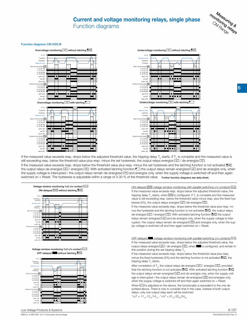
6
Measuring &
monitoring relays
CM Range
Low Voltage Products & Systems 6.107ABB Inc. • 888-385-1221 • www.abb.us/lowvoltage 1SXU000023C0202 Rev. A
If the measured value exceeds resp. drops below the adjusted threshold value, the tripping delay TV starts. If TV is complete and the measured value is still exceeding resp. below the threshold value plus resp. minus the set hysteresis, the output relays energize h / de-energize g. If the measured value exceeds resp. drops below the threshold value plus resp. minus the set hysteresis and the latching function is not activated e, the output relays de-energize h / energize g. With activated latching function f the output relays remain energized h and de-energize only, when the supply voltage is interrupted / the output relays remain de-energized g and energize only, when the supply voltage is switched off and then again switched on = Reset. The hysteresis is adjustable within a range of 3-30 % of the threshold value.
Function diagrams CM-ESS.M
Overvoltage monitoring d without latching e
Overvoltage monitoring d with latching f
Undervoltage monitoring c without latching e
Undervoltage monitoring c with latching f
A1-A2
11-14 (15-18)11-12 (15-16)
21-24 (25-28)21-22 (25-26)
11-14 (15-18)11-12 (15-16)
21-24 (25-28)21-22 (25-26)
open
closed
Threshold
Hysteresis
Measured value
green LED
red LED
yellow LED
< TV
green LED
red LED
yellow LED
Open-circuit principle
Closed-circuit principle
TV< TV
A1-A2
11-14 (15-18)11-12 (15-16)
21-24 (25-28)21-22 (25-26)
11-14 (15-18)11-12 (15-16)
21-24 (25-28)21-22 (25-26)
open
closed
Threshold
Hysteresis
Measured value
green LED
red LED
yellow LED
green LED
red LED
yellow LED
Open-circuit principle
Closed-circuit principle
TV< TV
Reset
< TV
A1-A2
11-14 (15-18)11-12 (15-16)
21-24 (25-28)21-22 (25-26)
11-14 (15-18)11-12 (15-16)
21-24 (25-28)21-22 (25-26)
closed
open
Threshold
Hysteresis
Measured value
green LED
red LED
yellow LED
green LED
red LED
yellow LED
Open-circuit principle
Closed-circuit principle
TV < TV< TV
A1-A2
11-14 (15-18)11-12 (15-16)
21-24 (25-28)21-22 (25-26)
11-14 (15-18)11-12 (15-16)
21-24 (25-28)21-22 (25-26)
closed
open
Threshold
Hysteresis
Measured value
green LED
red LED
yellow LED
green LED
red LED
yellow LED
Open-circuit principle
Closed-circuit principle
TV < TV
Reset
< TV
ON-delayed A voltage window monitoring with parallel switching c/o contacts j:If the measured value exceeds resp. drops below the adjusted threshold value, the tripping delay TV starts, when A is configured. If TV is complete and the measured value is still exceeding resp. below the threshold value minus resp. plus the fixed hys-teresis (5%), the output relays energize h /de-energize g.If the measured value exceeds resp. drops below the threshold value plus resp. mi-nus the hysteresis and the latching function is not activated e, the output relays de-energize h / energize g. With activated latching function e the output relays remain energized h and de-energize only, when the supply voltage is inter-rupted / the output relays remain de-energized g and energize only, when the sup-ply voltage is switched off and then again switched on = Reset.
OFF-delayed B voltage window monitoring with parallel switching c/o contacts j:If the measured value exceeds resp. drops below the adjusted threshold value, the output relays energize h / de-energize g, when B is configured, and remain in this position during the set tripping delay TV.If the measured value exceeds resp. drops below the threshold value plus resp. minus the fixed hysteresis (5%) and the latching function is not activated e, the tripping delay TV starts.
After completion of TV, the output relays de-energize h / energize g, provided that the latching function is not activated e. With activated latching function e the output relays remain energized h and de-energize only, when the supply volt-age is interrupted / the output relays remain de-energized g and energize only, when the supply voltage is switched off and then again switched on = Reset.
When i is adjusted on the device, the functionality is equivalent to the one de-scribed above. There is only to consider that in this case, instead of both output relays, only one output relay each will be switched. “>U“ = 1115-1216/1418 ; “<U“ = 2125-2226/2428
Voltage window monitoring 1x2 c/o contact j
ON-delayed A without latching e
Voltage window monitoring 1x2 c/o contact j
OFF-delayed B without latching e
Further function diagrams see data sheet.
A1-A2
11-14 (15-18)11-12 (15-16)
21-24 (25-28)21-22 (25-26)
11-14 (15-18)11-12 (15-16)
21-24 (25-28)21-22 (25-26)
open
closed
Thresholdmax
Hysteresis
green LED
red LED
yellow LED
green LED
red LED
yellow LED
Open-circuit principle
Closed-circuit principle
TV < TVHysteresis
Measured value
Thresholdmin
< TV
A1-A2
11-14 (15-18)11-12 (15-16)
21-24 (25-28)21-22 (25-26)
11-14 (15-18)11-12 (15-16)
21-24 (25-28)21-22 (25-26)
closed
open
Thresholdmax
Hysteresis
green LED
red LED
yellow LED
green LED
red LED
yellow LED
Open-circuit principle
Closed-circuit principle
TV TVHysteresis
Measured value
Thresholdmin
Current and voltage monitoring relays, single phaseFunction diagrams

6
Measuring &
monitorin
g relays
CM Range
6.108 Low Voltage Products & Systems
1SXU000023C0202 Rev. A ABB Inc. • 888-385-1221 • www.abb.us/lowvoltage
A1 A2
A1 1115
B1 B2 B3
A2
1115
12161418
1418 1216
C
B1 B2 B3
C
A1-A2 Control supply voltage
B1-C Measuring range 1: 3-30 mA or 0.3-1.5 A
B2-C Measuring range 2: 10-100 mA or 1-5 A
B3-C Measuring range 3: 0.1-1 A or 3-15 A
1115-1216/1418 Output contacts - open-circuit principle
Connection diagram CM-SRS.1, CM-SRS.2
A1 A2
2125
22262428
A1 1115 2125
B1 B2 B3
2428 2226 A2
1115
12161418
1418 1216 C
B1 B2 B3
C
A1-A2 Control supply voltage
B1-C Measuring range 1: 3-30 mA or 0.3-1.5 A
B2-C Measuring range 2: 10-100 mA or 1-5 A
B3-C Measuring range 3: 0.1-1 A or 3-15 A
1115-1216/1418 Output contacts - 2125-2226/2428 open-circuit principle
A1 A2
2125
22262428
A1 1115 2125
B1 B2 B3
2428 2226 A2
1115
12161418
1418 1216 C
B1 B2 B3
C
A1-A2 Control supply voltage
B1-C Measuring range 1: 3-30 mA bzw. 0.3-1.5 A
B2-C Measuring range 2: 10-100 mA bzw. 1-5 A
B3-C Measuring range 3: 0.1-1 A bzw. 3-15 A
1115-1216/1418 Output contacts - 2125-2226/2428 open-or closed circuit principle
Connection diagram CM-SRS.M
A1 A2
2125
22262428
A1 1115 2125
B1 B2 B3
2428 2226 A2
1115
12161418
1418 1216 C
B1 B2 B3
C
Connection diagram CM-SFS.2
A1-A2 Control supply voltage
B1-C Measuring range 1: 3-30 mA or 0.3-1.5 A
B2-C Measurign range 2: 10-100 mA or 1-5 A
B3-C Measuring range 3: 0.1-1 A or 3-15 A
1115-1216/1418 Output contacts - 2125-2226/2428 open-or closed circuit principle
DIP switch functions CM-SRS.1, CM-SRS.2
1 ON Undercurrent monitoring OFF Overcurrent monitoring
OFF = Default
closed
open
Position 4 123
ON
OFF
I
I
DIP switch functions CM-SRS.M
1 ON Undercurrent monitoring 2 ON Closed-circuit principle OFF Overcurrent monitoring OFF Open-circuit principle
3 ON Latching function activated OFF = Default OFF Latching function not activated
closed
open
2x1 c/o
1x2 c/o
Position 4 123
ON
OFF
DIP switch function CM-SFS.2
1 ON OFF-delay 2 ON Closed-circuit principle OFF ON-delay OFF Open-circuit principle
3 ON Latching function activated 4 ON 2x1 c/o contact OFF Latching function not activated OFF 1x2 c/o contacts
OFF = Default
closed
open V
V
Position 4 123
ON
OFF
DIP switch functions CM-ESS.M
1 ON Undervoltage monitoring 2 ON Closed-circuit principle OFF Overvoltage monitoring OFF Open-circuit principle
3 ON Latching function activated OFF = Default OFF Latching function not activated
A1 A2
2125
22262428
A1 1115 2125
B
2428 2226 A2
1115
12161418
1418 1216 C
B
C
A1-A2 Control supply voltage
B-C Measuring ranges: 3-30 V; 6-60 V; 30-300 V; 60-600 V
1115-1216/1418 Output contacts - 2125-2226/2428 Open- or closed circuit principle
Connection diagram CM-ESS.M
Current and voltage monitoring relays, single phaseConnection diagramsDIP switches
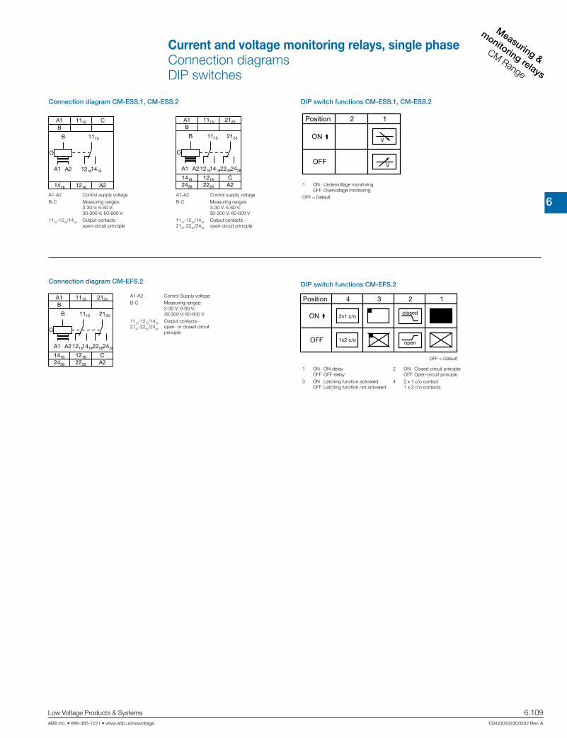
6
Measuring &
monitoring relays
CM Range
Low Voltage Products & Systems 6.109ABB Inc. • 888-385-1221 • www.abb.us/lowvoltage 1SXU000023C0202 Rev. A
closed
open
2x1 c/o
1x2 c/o
Position 4 123
ON
OFF
DIP switch functions CM-EFS.2
OFF = Default
A1 A2
2125
22262428
A1 1115 2125
B
2428 2226 A2
1115
12161418
1418 1216 C
B
C
Connection diagram CM-EFS.2
A1-A2 Control Supply voltage
B-C Measuring ranges: 3-30 V; 6-60 V; 30-300 V; 60-600 V
1115-1216/1418 Output contacts - 2125-2226/2428 open- or closed circuit principle
A1 A2
A1 1115
B
A2
1115
12161418
1418 1216
C
B
C
Connection diagram CM-ESS.1, CM-ESS.2
A1 A2
2125
22262428
A1 1115 2125
B
2428 2226 A2
1115
12161418
1418 1216 C
B
C
A1-A2 Control supply voltage
B-C Measuring ranges: 3-30 V; 6-60 V; 30-300 V; 60-600 V
1115-1216/1418 Output contacts - 2125-2226/2428 open-circuit principle
A1-A2 Control supply voltage
B-C Measuring ranges: 3-30 V; 6-60 V; 30-300 V; 60-600 V
1115-1216/1418 Output contacts - open-circuit principle
DIP switch functions CM-ESS.1, CM-ESS.2
1 ON Undervoltage monitoring OFF Overvoltage monitoring
OFF = Default
1 ON ON-delay 2 ON Closed-circuit principle OFF OFF-delay OFF Open-circuit principle
3 ON Latching function activated 4 2 x 1 c/o contact OFF Latching function not activated 1 x 2 c/o contacts
Current and voltage monitoring relays, single phaseConnection diagramsDIP switches

6
Measuring &
monitorin
g relays
CM Range
6.110 Low Voltage Products & Systems
1SXU000023C0202 Rev. A ABB Inc. • 888-385-1221 • www.abb.us/lowvoltage
Type CM-SRS.1 CM-SRS.2 CM-SRS.M CM-SFS.2
Input circuit - Supply circuit A1-A2
Rated control supply voltage UsA1-A2 110-130 V ACA1-A2 220-240 V ACA1-A2 24-240 V AC/DC
Rated control supply voltage Us tolerance -15...+10 %Rated frequency AC versions 50/60 Hz
AC/DC versions 50/60 Hz or DCCurrent / power consumption see data sheetsPower failure buffering time 20 msTransient overvoltage protection VaristorsInput circuit - Measuring circuit B1/B2/B3-C
Monitoring function over- or undercurrent monitoring configurable
over- and under-current monitoring
Measuring method True RMS measuring principle
Measuring inputsTerminal connection
Measuring ranges AC/DCInput resistance
Pulse overload capacity t < 1 sContinuous capacity
Threshold value(s) adjustable within the indicated measuring rangeSetting accuracy of threshold value 10 %Repeat accuracy (constant parameters) 0.07 % of full scaleHysteresis related to the threshold value 3-30 % adjustable 5 % fixedMeasuring signal frequency range DC / 15 Hz - 2 kHzRated measuring signal frequency range DC / 50-60 HzMaximum response time AC: 80 ms / DC: 120 msAccuracy within the control supply voltage tolerance U m 0.5 %Accuracy within the temperature range U m 0.06 % / °CTiming circuitStart-up delay TS none 0 or 0.1-30 s adjustableTripping delay TV none 0 or 0.1-30 s adjustableRepeat accuracy (constant parameters) w0.07 % of full scaleAccuracy within the control supply voltage tolerance - t m 0.5 %Accuracy within the temperature range - t m 0.06 % / °CIndication of operational statesControl supply voltage U/T: green LED V: control supply voltage applied,
X: start-up delay TS active, W: tripping delay TV active
Measured value I: red LED V: overcurrent, W: undercurrent
Relay status R: yellow LED V: relay energized, no latching function Z: relay energized, active latching function
Y: relay de-energized, active latching function
Output circuits 11(15)-12(16)/14(18), 21(25)-22(26)/24(28) - Relays
Kind of output1 c/o contact 2 c/o contacts
1x2 c/o contacts or 2x1 c/o contact
configurableOperating principle 1)
open-circuit principle open- or closed-circuit principle configurable
Contact material AgNi
Rated operational voltage Ue IEC/EN 60947-1 250 V
Minimum switching voltage / minimum switching current 24 V / 10 mA
Maximum switching voltage / maximum switching current 250 V AC / 4 A ACRated operational current Ie(IEC/EN 60947-5-1)
AC12 (resistive) at 230 V 4 AAC15 (inductive) at 230 V 3 A
DC12 (resistive) at 24 V 4 ADC13 (inductive) at 24 V 2 A
AC rating (UL 508)
Utilization category (Control Circuit Rating Code) B 300max. rated operational voltage 300 V AC
max. continuous thermal current at B 300 5 Amax. making/breaking apparent power
(Make/Break) at B 3003600/360 VA
Mechanical lifetime 30x106 switching cycles
Electrical lifetime (AC12, 230 V, 4 A) 0.1x10⁶ switching cycles
Max. fuse rating to achieve short-circuit protection
n/c contact 6 A fast-acting 10 A fast-acting 6 A fast-acting
n/o contact 10 A fast-acting
CM-SxS.x1 CM-SxS.x2B1-C B2-C B3-C B1-C B2-C B3-C
3-30 mA 10-100 mA 0.1-1 A 0.3-1.5 A 1-5 A 3-15 A 2)
3.3 q 1 q 0.1 q 0.05 q 0.01 q 0.0025 q500 mA 1 A 10 A 15 A 50 A 100 A50 mA 150 mA 1.5 A 2 A 7 A 17 A
1) Open-circuit principle: output relay energizes if the measured value exceeds b / falls below a the adjusted threshold value Closed-circuit principle: output relay de-energizes if measured value exeeds b / falls below a the adjusted threshold value
Current and voltage monitoring relays, single phaseTechnical data

6
Measuring &
monitoring relays
CM Range
Low Voltage Products & Systems 6.111ABB Inc. • 888-385-1221 • www.abb.us/lowvoltage 1SXU000023C0202 Rev. A
Type CM-SRS.1 CM-SRS.2 CM-SRS.M CM-SFS.2
General dataMTBF on requestDuty time 100%Dimensions
(W x H x D)
product dimensions 22.5 x 85.6 x 103.7 mm (0.89 x 3.37 x 4.08 in)packaging dimensions 97 x 109 x 30 mm (3.82 x 4.29 x 1.18 in)
Weight net weight depending on device, see ordering details
gross weight depending on device, see ordering detailsMounting DIN rail (IEC/EN 60715),
snap-on mounting without any toolMounting position anyMinimum distance to other units 10mm (0.39in) at measured current > 10 AMaterial of housing UL 94 V-0Degree of protection housing / terminals IP50 / IP20Electrical connectionWire size Screw connection technology Easy Connect Technology (Push-in)
fine-strand with(out) wire end ferrule 1 x 0.5-2.5 mm2 (1 x 20-14 AWG)2 x 0.5-1.5 mm2 (2 x 20-16 AWG)
2 x 0.5-1.5 mm2 (2 x 20-16 AWG)
rigid 1 x 0.5-4 mm2 (1 x 20-12 AWG)2 x 0.5-2.5 mm2 (2 x 20-14 AWG)
2 x 0.5-1.5 mm2 (2 x 20-16 AWG)
Stripping length 8 mm (0.32 in)Tightening torque 0.6-0.8 Nm (5.31-7.08 lb.in) -Environmental dataAmbient temperature range operation / storage -20...+60 °C / -40...+85 °CDamp heat (IEC 60068-2-30) 55 °C, 6 cyclesVibration (sinusoidal) (IEC/EN 60255-21-1) Class 2Shock (IEC/EN 60255-21-2) Class 2Isolation dataRated insulation voltage (VDE 0110, IEC 60947-1, IEC/EN 60255-5)
supply / measuring circuit / output 600 V
supply / output 1/2 250 VRated impulse withstand voltage Uimp (IEC/EN 60947-1, IEC/EN 60255-5)
supply / measuring circuit / output 6 kV 1.2/50 µs
supply / output 1/2 4 kV 1.2/50 µsPollution degree (VDE 0110, IEC 664, IEC/EN 60255-5) 3Overvoltage category (VDE 0110, IEC 664, IEC/EN 60255-5) IIIStandardsProduct standard IEC/EN 60255-6Low Voltage Directive 2006/95/ECEMC Directive 2004/108/ECElectromagnetic compatibilityInterference immunity to IEC/EN 61000-6-2
electrostatic discharge IEC/EN 61000-4-2 Level 3radiated, radio-frequency, electromagnetic field
IEC/EN 61000-4-3Level 3
electrical fast transient / burst IEC/EN 61000-4-4 Level 3surge IEC/EN 61000-4-5 Level 3
conducted disturbances, induced by radio-frequency fields
IEC/EN 61000-4-6Level 3
Interference emission IEC/EN 61000-6-3high-frequency radiated IEC/CISPR 22; EN 55022 Class Bhigh-frequency conducted IEC/CISPR 22; EN 55022 Class B
2) In case of measured currents > 10 A, lateral spacing has to be min. 10 mm
Current monitoring relays, single phaseTechnical data

6
Measuring &
monitorin
g relays
CM Range
6.112 Low Voltage Products & Systems
1SXU000023C0202 Rev. A ABB Inc. • 888-385-1221 • www.abb.us/lowvoltage
Type CM-ESS.1 CM-ESS.2 CM-ESS.M CM-EFS.2
Input circuit - Supply circuit A1-A2
Rated control supply voltage Us A1-A2 110-130 V ACA1-A2 220-240 V ACA1-A2 24-240 V AC/DC
Rated control supply voltage Us tolerance -15...+10 %Rated frequency AC versions 50/60 Hz
AC/DC versions 50/60 Hz or DCCurrent / power consumption see data sheetPower failure buffering time 20 msTransient overvoltage protection VaristorsInput circuit - Measuring circuit B-C
Monitoring function Over or undervoltage monitoring configurable
Over and undervoltage monitoring
configurableMeasuring method True RMS measuring principleMeasuring inputs CM-ExS
Terminal connection B-C B-C B-C B-CMeasuring range AC/DC 3-30 V 6-60 V 30-300 V 60-600 V
Input resistance 600 kq 600 kq 600 kq 600 kqPulse overload capacity t < 1 s 800 V 800 V 800 V 800 V
Continous capacity 660 V 660 V 660 V 660 VThreshold value(s) adjustable within the indicated measuring rangeSetting accuracy of threshold value 10 %Repeat accuracy (constant parameters) w0.07 % of full scaleHysteresis related to the threshold value 3-30 % adjustable 5 % fixedMeasuring signal frequency range DC / 15 Hz - 2 kHzRated measuring signal frequency range DC / 50-60 HzMaximum response time AC: 80 ms / DC: 120 msAccuracy within the control supply voltage tolerance U m 0.5 %Accuracy within the temperature range U m 0.06 % / °CTransient overvoltage protection VaristorsTiming circuitDelay time TV none 0 or 0.1-30 s adjustableRepeat accuracy (constant parameters) w0.07 % of full scaleAccuracy within the control supply voltage tolerance - t m 0.5 %Accuracy within the temperature range - t m 0.06 % / °CIndication of operational statesControl supply voltage U/T: green LED V: control supply voltage applied
W: tripping delay TV active
Measured value U: red LED V: overvoltage, W: undervoltage
Relay status R: yellow LED V: relay energized, no latching function Z: relay energized, active latching function
Y: relay de-energized, active latching function
Output circuits Kind of output
1 c/o contact 2 c/o contacts1x2 c/o contacts or
2x1 c/o contact configurable
Operating principle 1)open-circuit principle open- or closed-circuit principle
configurableContact material AgNiRated operational voltage Ue IEC/EN 60947-1 250 VMinimum switching voltage / minimum switching current 24 V / 10 mAMaximum switching voltage / maximum switching current 250 V AC / 4 A ACRated operational current Ie (IEC/EN 60947-5-1)
AC12 (resistive) at 230 V 4 AAC15 (inductive) at 230 V 3 A
DC12 (resistive) at 24 V 4 ADC13 (inductive) at 24 V 2 A
1) Open-circuit principle: output relay energizes if the measured value exceeds d / falls below c the adjusted threshold value Closed-circuit principle: output relay de-energizes if measured value exeeds d / falls below c the adjusted threshold value2)
Voltage monitoring relays, single phaseTechnical data

6
Measuring &
monitoring relays
CM Range
Low Voltage Products & Systems 6.113ABB Inc. • 888-385-1221 • www.abb.us/lowvoltage 1SXU000023C0202 Rev. A
Type CM-ESS.1 CM-ESS.2 CM-ESS.M CM-EFS.2
AC rating (UL 508)
Utilization category (Control Circuit Rating Code) B 300max. rated operational voltage 300 V AC
max. continuous thermal current at B 300 5 Amax. making/breaking apparent power
(Make/Break) at B 3003600/360 VA
Mechanical lifetime 30x106 switching cyclesElectrical lifetime (AC12, 230 V, 4 A) 0.1x10⁶ switching cyclesMax. fuse rating to achieveshort-circuit protection
n/c contact 6 A fast-acting 10 A fast-acting 6 A fast-actingn/o contact 10 A fast-acting
General dataMTBF on requestDuty time 100%Dimensions (W x H x D) product dimensions 22.5 x 85.6 x 103.7 mm (0.89 x 3.37 x 4.08 in)
packaging dimensions 97 x 109 x 30 mm (3.82 x 4.29 x 1.18 in)Weight net weight depending on device, see ordering details
gross weight depending on device, see ordering detailsMounting DIN rail (IEC/EN 60715),
snap-on mounting without any toolMounting position anyMinimum distance to other units vertical / horizontal not necessary / not necessaryMaterial of housing UL 94 V-0Degree of protection housing / terminals IP50 / IP20Electrical connectionWire size Screw connection technology Easy Connect Technology (Push-in)
fine-strand with(out) wire end ferrule 1 x 0.5-2.5 mm2 (1 x 20-14 AWG)2 x 0.5-1.5 mm2 (2 x 20-16 AWG)
2 x 0.5-1.5 mm2 (2 x 20-16 AWG)
rigid 1 x 0.5-4 mm2 (1 x 20-12 AWG)2 x 0.5-2.5 mm2 (2 x 20-14 AWG)
2 x 0.5-1.5 mm2 (2 x 20-16 AWG)
Stripping length 8 mm (0.32 in)Tightening torque 0.6-0.8 Nm (5.31-7.08 lb.in) -Isolation data
Rated insulation voltage (VDE 0110,IEC 60947-1, IEC/EN 60255-5)
supply / measuring circuit / output
600 V
supply / output 1/2 250 V
Rated impulse withstand voltage Uimp(IEC/EN 60947-1, IEC/EN 60255-5)
supply / measuring circuit / output
6 kV 1.2/50 µs
supply / output 1/2 4 kV 1.2/50 µsPollution degree (VDE 0110, IEC 664, IEC/EN 60255-5) 3Overvoltage category (VDE 0110, IEC 664, IEC/EN 60255-5) IIIStandardsProduct standard IEC/EN 60255-6Low Voltage Directive 2006/95/ECEMC Directive 2004/108/ECElectromagnetic compatibilityInterference immunity to IEC/EN 61000-6-2
electrostatic discharge IEC/EN 61000-4-2 Level 3radiated, radio-frequency, electromagnetic field
IEC/EN 61000-4-3Level 3
electrical fast transient / burst IEC/EN 61000-4-4 Level 3surge IEC/EN 61000-4-5 Level 3conducted disturbances, induced by radio-frequency fields
IEC/EN 61000-4-6Level 3
Interference emission IEC/EN 61000-6-3high-frequency radiated IEC/CISPR 22; EN 55022 Class Bhigh-frequency conducted IEC/CISPR 22; EN 55022 Class B
Voltage monitoring relays, single phaseTechnical data

6
Measuring &
monitorin
g relays
CM Range
6.114 Low Voltage Products & Systems
1SXU000023C0202 Rev. A ABB Inc. • 888-385-1221 • www.abb.us/lowvoltage

6
Measuring &
monitoring relays
CM Range
Low Voltage Products & Systems 6.115ABB Inc. • 888-385-1221 • www.abb.us/lowvoltage 1SXU000023C0202 Rev. A
Three-phase monitoring relaysBenefits, advantages, & applications
Thre
e-ph
ase
mon
itorin
g re
lays
CM
-E R
ange

6
Measuring &
monitorin
g relays
CM Range
6.116 Low Voltage Products & Systems
1SXU000023C0202 Rev. A ABB Inc. • 888-385-1221 • www.abb.us/lowvoltage
Three-phase monitoring relaysBenefits, advantages, & applications
Expanded functionality
ABB’s new generation of three-phase monitoring relays feature additional functions making the application field for the devices considerably larger.
Selectable phase sequence monitoring
The phase sequence monitoring can be switched off by means of a rotary switch or a DIP switch. This enables monitoring of three-phase mains where phase sequence is not relevant for the application, for example in case of motors with forward and reverse rotation, heating applications, etc.
Automatic phase sequence correction
The automatic phase sequence correction is activated by means of a DIP switch. With activated phase sequence correction, it is ensured that for any non-fixed or portable equipment, e.g. construction machinery, the correct phase sequence is always applied to the input terminals of the load. For details regarding the wiring, please see function description / diagrams.
Structure of the type designation
CM-_ _ x.yzx: width of enclosurey: Control supply voltage / measuring range
1 110, 115, 120, 127 V supply systems (phase-neutral)
2 220, 230, 240 V supply systems (phase-neutral)
3 200, 208, 220, 230, 240, 257, 260 V supply systems (phase-phase)
4 440, 460 V supply systems (phase-phase)
5 480, 500 V supply systems (phase-phase)
6 575, 600 V supply systems (phase-phase)
7 660, 690 V supply systems (phase-phase)
8 200, 400 V supply systems (phase-phase)
z: Rated frequency / output circuit
1 50/60 Hz – 1x2 c/o
2 50/60 Hz – 1x2 or 2x1 c/o
3 50/60/400 Hz – 1x2 oder 2x1 c/o
Phase unbalance monitoring
If the supply by the three-phase system is unbalanced due to uneven dis-tribution of the load, the motor will convert a part of the energy into reac-tive power. This energy gets lost unexploited; also the motor is exposed to higher thermal strain. Other thermal protection devices fail to detect con-tinuing unbalances which can lead to damage or destruction of the motor. The CM range three-phase monitors with phase unbalance monitoring can reliably detect this critical situation.
Phase sequence
Changing the phase sequence during operation or a wrong phase se-quence prior to startup causes a change of the rotational direction of the connected device. Generators, pumps or fans rotate in the wrong direction and the installation is no longer working properly. Especially for moveable equipment, such as construction machinery, phase sequence detection prior to the startup process is highly reasonable.
Phase loss
In case of phase loss, undefined stats of the installation are likely to occur. E.g. the startup process of motors is disturbed. All three-phase monitors of the ABB CM range detect a phase loss as soon as the voltage of one phase drops below 60% of its nominal value.
Voltage monitoring
All electric devices can be damaged when operated continuously in a net-work with out-of-range voltages. For example, safe starting is not ensured in case of undervoltage. Also, the switching state of a contactor is not clearly defined when operated in a „forbidden“ voltage range. This can lead to undefined stats of the installtion and cause damage or destruction of valuable parts.
Characteristics of the CM range three-phase monitors
Adjustable phase unbalance threshold value 1)
Adjustable ON-delay/OFF-delay time 1)
Dual frequency measuring 50/60 Hz Powered by the measuring circuit 1 n/o contact, 1 or 2 contacts LED status indication
Approvals: A C D,E K Marks: a b Multifunctional and single-functional devices Phase loss monitoring Phase sequence monitoring 1)
Over- and undervoltage monitoring (fixed or adjustable)1)
Wide-range operating voltage guarantees world-wide operation
1) depending on device type
1
3
2
4
1 Threshold value Vmin/Vmax
2 R/T: yellow LED Relay status, timing
F1: red LED fault message
F2: red LED failure:
- overvoltage: F1
- undervoltage: F2
- phase unbalance: F1 and F2 constant
- phase loss: F1 on F2 flashing
- phase sequence: F1 and F2 alternately flashing
3 Adjustment of the tripping delay
4 Time setting 0.1-10 s Phase sequence and phase loss are indicated without any time delay
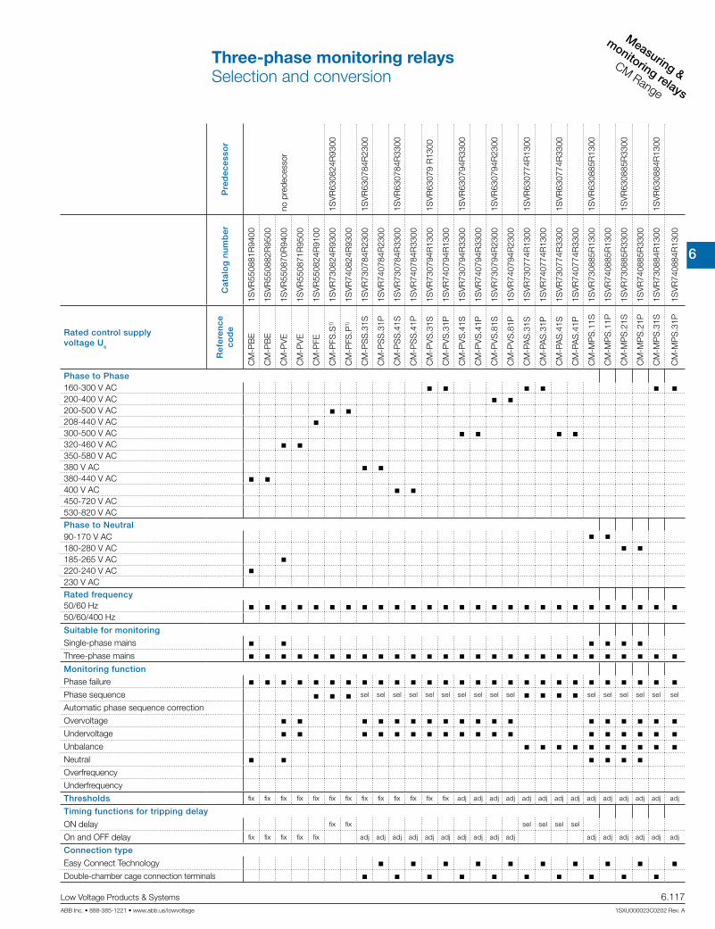
6
Measuring &
monitoring relays
CM Range
Low Voltage Products & Systems 6.117ABB Inc. • 888-385-1221 • www.abb.us/lowvoltage 1SXU000023C0202 Rev. A
Pre
dec
esso
r
no p
rede
cess
or
1SV
R63
0824
R93
00
1SV
R63
0784
R23
00
1SV
R63
0784
R33
00
1SV
R63
079
R13
00
1SV
R63
0794
R33
00
1SV
R63
0794
R23
00
1SV
R63
0774
R13
00
1SV
R63
0774
R33
00
1SV
R63
0885
R13
00
1SV
R63
0885
R33
00
1SV
R63
0884
R13
00
Cat
alo
g n
um
ber
1SV
R55
0881
R94
00
1SV
R55
0882
R95
00
1SV
R55
0870
R94
00
1SV
R55
0871
R95
00
1SV
R55
0824
R91
00
1SV
R73
0824
R93
00
1SV
R74
0824
R93
00
1SV
R73
0784
R23
00
1SV
R74
0784
R23
00
1SV
R73
0784
R33
00
1SV
R74
0784
R33
00
1SV
R73
0794
R13
00
1SV
R74
0794
R13
00
1SV
R73
0794
R33
00
1SV
R74
0794
R33
00
1SV
R73
0794
R23
00
1SV
R74
0794
R23
00
1SV
R73
0774
R13
00
1SV
R74
0774
R13
00
1SV
R73
0774
R33
00
1SV
R74
0774
R33
00
1SV
R73
0885
R13
00
1SV
R74
0885
R13
00
1SV
R73
0885
R33
00
1SV
R74
0885
R33
00
1SV
R73
0884
R13
00
1SV
R74
0884
R13
00
Rated control supply voltage Us
Ref
eren
ceco
de
CM
-PB
E
CM
-PB
E
CM
-PV
E
CM
-PV
E
CM
-PFE
CM
-PFS
.S1)
CM
-PFS
.P1)
CM
-PS
S.3
1S
CM
-PS
S.3
1P
CM
-PS
S.4
1S
CM
-PS
S.4
1P
CM
-PV
S.3
1S
CM
-PV
S.3
1P
CM
-PV
S.4
1S
CM
-PV
S.4
1P
CM
-PV
S.8
1S
CM
-PV
S.8
1P
CM
-PA
S.3
1S
CM
-PA
S.3
1P
CM
-PA
S.4
1S
CM
-PA
S.4
1P
CM
-MP
S.1
1S
CM
-MP
S.1
1P
CM
-MP
S.2
1S
CM
-MP
S.2
1P
CM
-MP
S.3
1S
CM
-MP
S.3
1P
Phase to Phase160-300 V AC 200-400 V AC 200-500 V AC 208-440 V AC 300-500 V AC 320-460 V AC 350-580 V AC380 V AC 380-440 V AC 400 V AC 450-720 V AC530-820 V ACPhase to Neutral90-170 V AC 180-280 V AC 185-265 V AC 220-240 V AC 230 V ACRated frequency50/60 Hz 50/60/400 Hz
Suitable for monitoring
Single-phase mains Three-phase mains Monitoring function
Phase failure Phase sequence sel sel sel sel sel sel sel sel sel sel sel sel sel sel sel sel
Automatic phase sequence correction
Overvoltage Undervoltage Unbalance Neutral Overfrequency
Underfrequency
Thresholds fix fix fix fix fix fix fix fix fix fix fix fix fix adj adj adj adj adj adj adj adj adj adj adj adj adj adj
Timing functions for tripping delay
ON delay fix fix sel sel sel sel
On and OFF delay fix fix fix fix fix adj adj adj adj adj adj adj adj adj adj adj adj adj adj adj adj
Connection type
Easy Connect Technology Double-chamber cage connection terminals
Three-phase monitoring relaysSelection and conversion

6
Measuring &
monitorin
g relays
CM Range
6.118 Low Voltage Products & Systems
1SXU000023C0202 Rev. A ABB Inc. • 888-385-1221 • www.abb.us/lowvoltage
Pre
dec
esso
r
1SV
R63
0884
R43
00
1SV
R63
0885
R43
00
1SV
R63
0884
R43
00
1SV
R65
0487
R83
00
1SV
R65
0488
R83
00
1SV
R65
0489
R83
00
Cat
alo
g n
um
ber
1SV
R73
0884
R33
00
1SV
R74
0884
R33
00
1SV
R73
0885
R43
00
1SV
R74
0885
R43
00
1SV
R73
0884
R43
00
1SV
R74
0884
R43
00
1SV
R75
0487
R83
00
1SV
R76
0487
R83
00
1SV
R75
0488
R83
00
1SV
R76
0488
R83
00
1SV
R75
0489
R83
00
1SV
R76
0489
R83
00
Rated control supply voltage Us
Ref
eren
ceco
de
CM
-MP
S.4
1S
CM
-MP
S.4
1P
CM
-MP
S.2
3S
CM
-MP
S.2
3P
CM
-MP
S.4
3S
CM
-MP
S.4
3P
CM
-MP
N.5
2S1)
CM
-MP
N.5
2P1)
CM
-MP
N.6
2S1)
CM
-MP
N.6
2P1)
CM
-MP
N.7
2S1)
CM
-MP
N.7
2P1)
Phase to Phase160-300 V AC200-400 V AC200-500 V AC208-440 V AC300-500 V AC 320-460 V AC350-580 V AC 380 V AC380-440 V AC400 V AC450-720 V AC 530-820 V AC Phase to Neutral90-170 V AC180-280 V AC 185-265 V AC220-240 V AC230 V ACRated frequency50/60 Hz 50/60/400 Hz Suitable for monitoring
Single-phase mains Three-phase mains Monitoring function
Phase failure Phase sequence sel sel adj adj adj adj adj adj adj adj adj adj
Automatic phase sequence correction adj adj adj adj adj adj adj adj adj adj
Overvoltage Undervoltage Unbalance Neutral Overfrequency
Underfrequency
Thresholds adj adj adj adj adj adj adj adj adj adj adj adj
Timing functions for tripping delay
ON delay
On and OFF delay adj adj adj adj adj adj adj adj adj adj adj adj
Connection type
Easy Connect Technology Double-chamber cage connection terminals
Three-phase monitoring relaysSelection and conversion

6
Measuring &
monitoring relays
CM Range
Low Voltage Products & Systems 6.119ABB Inc. • 888-385-1221 • www.abb.us/lowvoltage 1SXU000023C0202 Rev. A
DescriptionOnly reliable and continuous monitoring of a three-phase network guarantees the trouble-free and economic operation of machines and installations.
Ordering details
Rated control supply voltage =
measuring voltageMonitoring function Neutral monitoring
Referencecode
Catalognumber
Weight(1 pce)kg (lb)
3x380-440 V AC, 220-240 V AC Phase failure
detection (Single- and three-phase)
n CM-PBE 1) 1SVR550881R9400 0.08 (0.17)
3x380-440 V AC CM-PBE 1SVR550882R9500 0.08 (0.17)
3x320-460 V AC, 185-265 V AC
Over- / under-voltage and phase failure detection (Single- and three-phase)
n CM-PVE 1) 1SVR550870R9400 0.08 (0.17)
3x320-460 V AC CM-PVE 1SVR550871R9500 0.08 (0.17)
3x208-440 V AC Phase sequence monitoring and phase failure detection (Three-phase)
CM-PFE 2) 1SVR550824R9100 0.08 (0.17)
3x200-500 V AC CM-PFS 2) 1SVR430824R9300 0.15 (0.33)
3x380 V ACOver- / undervolt-age with fixed threshold values ± 10 %
CM-PSS.31S 1SVR730784R2300 0.132 (0.291)
CM-PSS.31P 1SVR740784R2300 0.123 (0.271)
3x400 V ACCM-PSS.41S 1SVR740784R3300 0.132 (0.291)
CM-PSS.41P 1SVR730784R3300 0.123 (0.271)
3x160-300 V AC
Over- and under-voltage with ad-justable threshold values (Three-phase)
CM-PVS.31S 1SVR730794R1300 0.141 (0.311)
CM-PVS.31P 1SVR740794R1300 0.132 (0.291)
3x300-500 V ACCM-PVS.41S 1SVR730794R3300 0.139 (0.306)
CM-PVS.41P 1SVR740794R3300 0.131 (0.289)
3x200-400 V ACCM-PVS.81S 1SVR730794R2300 0.136 (0.300)
CM-PVS.81P 1SVR740794R2300 0.128 (0.282)
3x160-300 V AC
Phase unbalance (Three-phase)
CM-PAS.31S 1SVR730774R1300 0.133 (0.293)
CM-PAS.31P 1SVR740774R1300 0.124 (0.273)
3x300-500 V ACCM-PAS.41S 1SVR730774R3300 0.132 (0.291)
CM-PAS.41P 1SVR740774R3300 0.123 (0.271)
CM-PAS.31P
CM-PSS.41P
CM-PBE
2) For applications where a reverse fed voltage >60% is expected, we recommend to use our three-phase monitoring relays for unbalance CM-PAS.xx
1) The version with neutral monitoring is also suitable for monitoring single-phase mains. For this, all three external conductors (L1,L2,L3) have to be jumpered and connected as one single conductor.
Three-phase monitoring relaysOrdering details

6
Measuring &
monitorin
g relays
CM Range
6.120 Low Voltage Products & Systems
1SXU000023C0202 Rev. A ABB Inc. • 888-385-1221 • www.abb.us/lowvoltage
Ordering details
Rated control supply voltage =
measuring voltageMonitoring function Neutral monitoring
Referencecode
Catalognumber
Weight(1 pce)kg (lb)
90-170 V AC
Multifunctional (Three-phase phase failure detection, Phase sequence moni-toring, overvolt-age, undervoltage, Phase unbalance)
n
CM-MPS.11S 1SVR730885R1300 0.148 (0.326)
CM-MPS.11P 1SVR740885R1300 0.137 (0.302)
180-280 V ACCM-MPS.21S 1SVR730885R3300 0.146 (0.322)
CM-MPS.21P 1SVR740885R3300 0.135 (0.298)
3x300-500 V AC
CM-MPS.31S 1SVR730884R1300 0.142 (0.313)
CM-MPS.31P 1SVR740884R1300 0.133 (0.293)
CM-MPS.41S 1SVR730884R3300 0.140 (0.309)
CM-MPS.41P 1SVR740884R3300 0.132 (0.291)
180-280 V AC
Multifunctional (Three-phase phase failure detection, Phase sequence moni-toring, overvolt-age, undervoltage, Phase unbalance)
n
CM-MPS.23S 1SVR730885R4300 0.149 (0.328)
CM-MPS.23P 1SVR740885R4300 0.138 (0.304)
3x300-500 V ACCM-MPS.43S 1SVR730884R4300 0.148 (0.327)
CM-MPS.43P 1SVR740884R4300 0.137 (0.302)
3x350-580 V ACCM-MPN.52S 1SVR750487R8300 0.230 (0.507)
CM-MPN.52P 1SVR760487R8300 0.226 (0.498)
3x450-720 V ACCM-MPN.62S 1SVR750488R8300 0.229 (0.505)
CM-MPN.62P 1SVR760488R8300 0.225 (0.496)
3x530-820 V ACCM-MPN.72S 1SVR750489R8300 0.224 (0.494)
CM-MPN.72P 1SVR760489R8300 0.220 (0.485)
3 x 400 V AC (L-L) / 230 V AC (L-N)
see Three-Phase overview page n CM-UFS.2 1SVR630736R1300 0.140 (0.309)
24-240 V AC/DCGrid feeding moni-toring (overvolt-age, undervoltage, change in grid frequency)
CM-UFD.M21 1SVR510730R0300 0.225 (0.496)
24 V AC/DC or 230 V AC CM-UFD.M32 1SVR510730R4400 0.395 (0.871)
CM-MPS.23P
CM-MPN.52P
Three-phase monitoring relaysOrdering details

6
Measuring &
monitoring relays
CM Range
Low Voltage Products & Systems 6.121ABB Inc. • 888-385-1221 • www.abb.us/lowvoltage 1SXU000023C0202 Rev. A
L1, L2, L3, N
13-14
L1, L2, L3, N L1, L2, L3, N L1, L2, L3, N L1, L2, L3, NL1, L2L3
N
ts
L1, L2, N
L3
tv
L2, L3, N
L1
<ts ts <tv
R: yellow LED
Measuring value
ts = Start-up delay xed 500 mstv = Tripping delay xed 150 ms
L1, L2, L3
13-14
L1, L2, L3 L1, L2, L3 L1, L2, L3 L1, L2, L3L1, L2
L3
ts
L1, L2
L3
tv
L1, L2
L3
<ts ts <tv
R: yellow LED
Measuring value
ts = Start-up delay xed 500 mstv = Tripping delay xed 150 ms
Function diagrams - Three-phase monitoring CM-PBE
with neutral
without neutral
Function diagrams - Three-phase monitoring CM-PVE
with neutral
without neutral
L1, L2, L3, N
13-14
Umax
Umax - 5 %
Umin + 5 %Umin
ts ts tstv tv<ts <tv
R: yellow LED
Measuring value
ts = Start-up delay xed 500 mstv = Tripping delay xed 500 msL1, L2, L3
13-14
Umax
Umax - 5 %
Umin + 5 %Umin
ts tststv tv<ts <tv
R: yellow LED
Measuring value
ts = Start-up delay xed 500 mstv = Tripping delay xed 500 ms
If all phases (and the neutral) are present, the output relay energizes after the start-up delay ts is complete. If a phase failure occurs, the tripping delay tv starts. When timing is complete, the output relay de-energizes. As soon as the voltage returns to the tolerance range, timing of ts starts. When timing is complete, the output relay re-energizes automatically. The yellow LED glows when the output relay is energized.
If all phases (and the neutral) are present with correct voltage, the output relay energizes after the start-up delay ts is complete. If the voltage exceeds or falls below the fixed threshold value or if a phase failure occurs, the tripping delay tv starts. When timing is complete, the output relay de-energizes. As soon as the voltage returns to the tolerance range, timing of ts starts. When timing is complete, the out-put relay re-energizes automatically. The yellow LED glows when the output relay is energized.
Function diagram - CM-PFE
L1, L2, L3
11-1211-14
L1, L2, L3 L1, L2, L3 L1, L2, L3L1, L3, L2 L1, L2
L3ts tv ts tvts
R: yellow LED
Measuring value
ts = Start-up delay xed 500 mstv = Tripping delay xed 500 ms
If all phases are present with the correct phase sequence, the out-put relay energizes after the start-up delay ts is complete. If a phase failure or a phase sequence error occurs, the tripping delay tv starts. When timing is complete, the output relay de-energizes. The yellow LED glows when the output relay is energized.In case of motors which continue running with only two phases, the CM-PFE detects phase failure if the reverse fed voltage is less than 60 % of the originally applied voltage.
ATTENTIONIf several CM-PFS units are placed side by side and the control supply voltage is higher than 415 V, spacing of at least 10 mm has to be kept between the individual units.
Function diagram - CM-PFS
L1, L2, L3
11-1211-14
21-2221-24
L1, L2, L3 L1, L2, L3 L1, L2, L3 L1, L2, L3L1, L3, L2 L1, L2 L1
L3 L2, L3ts
R: yellow LED
Measuring value
ts = start-up delay xed 500 ms
If all phases are present with the correct phase sequence, the output relay energizes after the start-up delay ts is complete. If a phase fail-ure or a phase sequence error occurs, the output relay de-energizes instantaneous. The yellow LED glows when the output relay is ener-gized.In case of motors which continue running with only two phases, the CM-PFS detects phase failure if the reverse fed voltage is less than 60 % of the originally applied voltage.
Three-phase monitoring relaysFunction diagrams

6
Measuring &
monitorin
g relays
CM Range
6.122 Low Voltage Products & Systems
1SXU000023C0202 Rev. A ABB Inc. • 888-385-1221 • www.abb.us/lowvoltage
K1
K1
K1
K3 H1
L1L2L3
N
16
28
A1
25
26
15
18
K2A2
A1
A2
-K3
L1
-F11
2
95
96
97
98
L2
3
4
L3
5
6
1
2
3
4
5
6-K2
-F2
1
2
3
4
5
6
1
3
5
2
4
6
M3 ~
W1V1U1
-M1
Phase sequence and phase failure monitoring CM-PSS.xx, CM-PVS.xx, CM.PAS.xx, CM-MPS.xx, CM-MPN.xx
Applying control supply voltage begins the fixed start-up delay tS. When tS is complete and all phases are present with correct voltage, the out-put relays energize and the yellow LED R/T glows.
Phase sequence monitoring
If phase sequence monitoring is activated, the output relays de- energize as soon as a phase sequence error occurs. The fault is dis-played by alternated flashing of the LEDs F1 and F2. The output relays re-energize automatically as soon as the phase sequence is correct again.
Phase failure monitoring
The output relays de-energize instantaneous if a phase failure occurs. The fault is indicated by lightning of LED F1 and flashing of LED F2. The output relays re-energize automatically as soon as the voltage returns to the tolerance range.
25-2625-28
L1, L2, L3
15-1615-18
L1, L2, L3 L1, L2, L3 L1, L2, L3 L1, L2, L3L1, L3, L2 L1, L2 L1
L3 L2, L3ts
F1: red LED
F2: red LED
R/T: yellow LED
Measuring value
ts = start-up delay xed 200 ms
L1, L2, L3
15-1615-18
tS2
tS1 tS1
L1, L2, L3L1, L2, L3 L1, L3, L2L1, L2
L3
25-2625-28
tS2
F1: red LED
F2: red LED
R/T: yellow LED
Measuring value
tS1 = start-up delay of R1 xed 250 mstS2 = start-up delay of R2 xed 200 ms
Automatic phase sequence correction CM-MPS.x3, CM-MPN.x2
This function can be selected only if phase sequence monitoring is ac-tivated k and operating mode 2x1 c/o (SPDT) contact j is selected.Applying control supply voltage begins the fixed start-up delay tS1. When tS1 is complete and all phases are present with correct voltage, output relay R1 energizes. Output relay R2 energizes when the fixed start-up delay tS2 is complete and all phases are present with correct phase sequence. Output relay R2 remains de-energized if the phase sequence is incorrect.If the voltage to be monitored exceeds or falls below the set threshold values for phase unbalance, over- or undervoltage or if a phase failure occurs, output relay R1 de-energizes and the LEDs F1 and F2 indicate the fault.Output relay R2 is responsive only to a false phase sequence. In con-junction with a reversing contactor combination, this enables an auto-matic correction of the rotation direction. See circuit diagrams on the right.
Interrupted neutral monitoring CM-MPS.11, CM-MPS.21, CM-MPS.23
The interruption of the neutral in the main to be monitored is detected by means of phase unbalance evaluation.Determined by the system, in case of unloaded neutral, i.e. symmetrical load between all three phases, it may happen that an interruption of the neutral will not be detected.If the star point is displaced by asymmetrical load in the three-phase main, an interrupted neutral will be detected.
Control circuit diagram (K1 = CM-MPS.xx or CM-MPN.xx)
Power circuit diagram
Displacement of the star point
Three-phase monitoring relaysFunction diagrams

6
Measuring &
monitoring relays
CM Range
Low Voltage Products & Systems 6.123ABB Inc. • 888-385-1221 • www.abb.us/lowvoltage 1SXU000023C0202 Rev. A
ON-delay A, 2x1 c/o contact i
OFF-delay B, 2x1 c/o contact i
OFF-delay B, 1x2 c/o contacts j
ON-delay A, 1x2 c/o contacts jOver- and undervoltage monitoring jCM-PSS.xx1), CM-PVS.xx2), CM-MPS.xx2), CM-MPN.xx2)
Applying control supply voltage begins the fixed start-up delay tS. When tS is complete and all phases are present with correct voltage and with correct phase sequence, the output relays energize and the yellow LED R/T glows.
Type of tripping delay = ON-delay
If the voltage to be monitored exceeds or falls below the fixed1) or set2) threshold value, the output relays de-energize after the set tripping delay tV is complete. The LED R/T flashes during timing and turns off as soon as the output relays de-energize.
The output relays re-energize automatically as soon as the voltage returns to the tolerance range, taking into account a fixed hysteresis of 5 % and the LED R/T glows.
Type of tripping delay = OFF-delay
If the voltage to be monitored exceeds or falls below the fixed1) or set2) threshold value, the output relays de-energize instantaneously and the LED R/T turns off.
As soon as the voltage returns to the tolerance range, taking into account a fixed hysteresis of 5 %, the output relays re-energize automatically after the set tripping delay tV is complete. The LED R/T flashes during timing and turns steady when timing is complete.
L1, L2, L3
15-1615-18
25-2625-28
> U> U - 5 %
< U + 5 %< U
ts <tv<tvtv
F1: red LED
F2: red LED
R/T: yellow LED
Measuring value
ts = start-up delay xed 200 mstv = adjustable tripping delay
L1, L2, L3
15-1615-18
25-2625-28
> U> U - 5 %
< U + 5 %< U
ts tv tv<tv
F1: red LED
F2: red LED
R/T: yellow LED
Measuring value
ts = start-up delay xed 200 mstv = adjustable tripping delay
Over- and undervoltage monitoring iCM-MPS.x3, CM-MPN.x2
Applying control supply voltage begins the fixed start-up delay tS. When tS is complete and all phases are present with correct voltage and with correct phase sequence, the output relays energize. The yellow LED R/T glows as long as at least one output relay is energized.
Type of tripping delay = ON-delay
If the voltage to be monitored exceeds or falls below the set threshold value, output relay R1 (overvoltage) or output relay R2 (undervoltage) de-energizes after the set tripping delay tV is complete. The LED R/T flashes during timing.The corresponding output relay re-energizes automatically as soon as the voltage returns to the tolerance range, taking into account a fixed hysteresis of 5 %.
Type of tripping delay = OFF-delay
If the voltage to be monitored exceeds or falls below the set threshold value, output relay R1 (overvoltage) or output relay R2 (undervoltage) de-energizes instantaneously.As soon as the voltage returns to the tolerance range, taking into account a fixed hysteresis of 5 %, the corresponding output relay re-energizes automatically after the set tripping delay tV is complete. The LED R/T flashes during timing.
L1, L2, L3
15-1615-18
> U> U - 5 %
< U + 5 %< U
ts tv tv<tv
25-2625-28
F1: red LED
F2: red LED
R/T: yellow LED
Measuring value
ts = start-up delay xed 200 mstv = adjustable tripping delay
25-2625-28
L1, L2, L3
15-1615-18
> U> U - 5 %
< U + 5 %< U
ts <tv<tvtv
F1: red LED
F2: red LED
R/T: yellow LED
Measuring value
ts = start-up delay xed 200 mstv = adjustable tripping delay
Three-phase monitoring relaysFunction diagrams

6
Measuring &
monitorin
g relays
CM Range
6.124 Low Voltage Products & Systems
1SXU000023C0202 Rev. A ABB Inc. • 888-385-1221 • www.abb.us/lowvoltage
Phase unbalance monitoring CM-PAS.xx, CM-MPS.xx, CM-MPN.xx
Applying control supply voltage begins the fixed start-up delay tS. When tS is com-plete and all phases are present with correct voltage and with correct phase se-quence, the output relays energize and the yellow LED R/T glows.
Type of tripping delay = ON-delay If the voltage to be monitored exceeds or falls below the set phase unbalance thresh-old value, the output relays de-energize after the set tripping delay tV is complete. The LED R/T flashes during timing and turns off as soon as the output relays de-energize.
The output relays re-energize automatically as soon as the voltage returns to the tol-erance range, taking into account a fixed hysteresis of 20 % and the LED R/T glows.
Type of tripping delay = OFF-delay If the voltage to be monitored exceeds or falls below the set phase unbalance thresh-old value, the output relays de-energize instantaneously and the LED R/T turns off.
As soon as the voltage returns to the tolerance range, taking into account a fixed hysteresis of 20 %, the output relays re-energize automatically after the set tripping delay tV is complete. The LED R/T flashes during timing and turns steady when timing is complete.
25-2625-28
L1, L2, L3
15-1615-18
ts <tv<tvtv
L1, L2, L3 L1, L2
L3
F1: red LED
F2: red LED
R/T: yellow LED
Measuring value
UnbalanceUnbalance - Hysteresis
Unbalance + HysteresisUnbalance
ts = start-up delay xed 200 mstv = adjustable tripping delay
L1, L2, L3
15-1615-18
L1, L2, L3 L1, L2
L3
ts tv tv<tv
25-2625-28
F1: red LED
F2: red LED
R/T: yellow LED
Measuring value
UnbalanceUnbalance - Hysteresis
Unbalance + HysteresisUnbalance
ts = start-up delay xed 200 mstv = adjustable tripping delay
OFF-delay B
ON-delay A
LED functions CM-PSS.xx, CM-PSV.xx, CM-PAS.xx, CM-MPS.xx, CM-MPN.xx
Function R/T: yellow LED
F1: red LED
F2: red LED
Control supply voltage applied, output relay energized V - -
Tripping delay tV active W - -
Phase failure - V W
Phase sequence - W alternating
Overvoltage - V -
Undervoltage - - V
Phase unbalance - V V
Interruption of the neutral - V W
Adjustment error 1) W W W
1) Possible misadjustments of the front-face operating controls:
Overlapping of the threshold values: An overlapping of the threshold values is given, if the threshold value for overvoltage is set to a smaller value than the threshold value for undervoltage.
DIP switch 3 = OFF and DIP switch 4 = ON: Automatic phase sequence correction is activated and selected operating mode is 1x2 c/o contacts
DIP switch 2 and 4 = ON: Phase sequence detection is deactivated and the auto-matic phase sequence correction is actived
Type of tripping delay CM-PSS.xx, CM-PSV.xx, CM-PAS.xx, CM-MPS.xx, CM-MPN.xx
The type of tripping delay A / B can be adjusted via a rotary (CM-PxS.xx) or a DIP switch (CM-MPx.xx).
Switch position ON-delay A: In case of a fault, the de-energizing of the output relays and the respective fault message are suppressed for the adjusted tripping delay tV.
Switch position OFF-delay B: In case of a fault, the output relays de-energize instantaneously and a fault mes-sage is displayed and stored for the length of the adjusted tripping delay tV. Thereby, also momentary undervoltage conditions are recognized.
Three-phase monitoring relaysFunction diagrams

6
Measuring &
monitoring relays
CM Range
Low Voltage Products & Systems 6.125ABB Inc. • 888-385-1221 • www.abb.us/lowvoltage 1SXU000023C0202 Rev. A
Over- and underfrequency monitoring
Applying control supply voltage begins the fixed start-up delay tS1. When tS1 is complete and all phases are present with correct voltage and frequency, the output relays energize.If the frequency to be monitored exceeds or falls below the fixed thresh-old value, the output relays deenergize instantaneously. The fault type is indicated by LEDs. As soon as the frequency returns to the tolerance range, taking into account a fixed hysteresis, the output relays re-ener-gize after the set restart delay tS2 is complete.
Function of the yellow LED
The yellow LED is flashing during timing and turns steady as soon as the output relays are energized.
Phase failure monitoring
Applying control supply voltage begins the fixed start-up delay tS1. When tS1 is complete and all phases are present with correct voltage and frequency, the output relays energize. They de-energize instanta-neously if a phase failure occurs. The fault is indicated by LEDs.As soon as all 3 phases are present again, the output relays re-energize automatically after the set restart delay tS2 is complete.
Over- and undervoltage monitoring
Applying control supply voltage begins the fixed start-up delay tS1. When tS1 is complete and all phases are present with correct voltage and frequency, the output relays energize.If the voltage to be monitored exceeds or falls below the fixed threshold value, the output relays de-energize instantaneously. The fault type is indicated by LEDs. As soon as the voltage returns to the tolerance range, taking into account a fixed hysteresis of 5 %, theoutput relays re-energize after the set restart delay tS2 is complete.
L1, L2, L3 (N)
15-16, 25-2615-18, 25-28
> U> U - Hyst.
< U + Hyst.< U
tS1 < tS2< tS2tS2
F1: red LED
F2: red LED
R/T: yellow LED
Measuring value
tS1 = Start-up delay prior to rst grid connection and after a short-time interruption, 1 s xedtS2 = Restart-up delay, adjustable
L1, L2, L3 (N)
15-16, 25-2615-18, 25-28
> f> f - Hyst.
< f + Hyst.< f
tS1 < tS2< tS2tS2
F1: red LED
F2: red LED
R/T: yellow LED
Measuring value
tS1 = Start-up delay prior to rst grid connection and after a short-time interruption, 1 s xedtS2 = Restart-up delay, adjustable
L1, L2, L3 (N)
15-16, 25-2615-18, 25-28
L1, L2, L3 L1, L2, L3L1, L2
L3tS1 tS2
F1: red LED
F2: red LED
R/T: yellow LED
Measuring value
tS1 = Start-up delay prior to rst grid connection and after a short-time interruption, 1 s xedtS2 = Restart-up delay, adjustable
Automatized grid connection instead of a permanently accessible switching point with a disconnection function
K1
K2
L1 NL2 L3 15
18 26 28
25
16
CM-UFS.x<U<<f<
L1L2L3N Low voltage grid
Inverter(s) Generator(s) Power plant
Externalswitch-off conditions
Coordination of short-circuit protection, welding free
May also be the inverter output. In this case, apply the signal of relay R2 to the relevant input
Function diagram legend
G Control supply voltage not applied / Output contact open / LED offB Control supply voltage applied / Output contact closed / LED glowing
LED Functions
Function R/T:
yellow LED
F1:
red LED
F2:
red LED
Output relay energized V - -
Delay active W - -
Overvoltage - V -
Undervoltage - - V
Overfrequency - W -
Underfrequency - - W
Phase failure - V W
Grid feeding monitoring CM-UFS.2
Three-phase monitoring relaysFunction diagrams

6
Measuring &
monitorin
g relays
CM Range
6.126 Low Voltage Products & Systems
1SXU000023C0202 Rev. A ABB Inc. • 888-385-1221 • www.abb.us/lowvoltage
L1-L2-L3 Control supply voltage = Measuring voltage
11-12/14 Output contact Closed-circuit principle
Connection diagram CM-PFE
Connection diagram CM-PFS
L1 L2
28252618
L3
L3 15
16 18 26 28
25L2L1
16 15
L1 L2
28252618
L3
L3 15
16 18 26 28
25L2L1
16 15
L1, L2, L3 Control supply voltage = measuring voltage15-16/18 Output contacts - 25-26/28 closed-circuit principle
Connection diagram CM-PSS.x1
L1, L2, L3 Control supply voltage = measuring voltage15-16/18 Output contacts - 25-26/28 closed-circuit principle
Connection diagram CM-PVS.x1
L1 L2
28252618
L3
L3 15
16 18 26 28
25L2L1
16 15
L1, L2, L3 Control supply voltage = measuring voltage15-16/18 Output contacts - 25-26/28 closed-circuit principle
Connection diagram CM-PAS.x1
L1 L2
282615 25
L3
L3 15
16 18 26 28
25L2L1
16 18
L1, L2, L3 Control supply voltage = measuring voltage15-16/18 Output contacts - 25-26/28 closed-circuit principle
Connection diagram CM-MPN.x2
L1-L2-L3 Control supply voltage = Measuring voltage
1115-1216 /1418, Output contact - 2125-2226/2428 Closed-circuit principle
L1, L2, L3, (N) Control supply voltage = Measuring voltage
13-14 Output contact - closed-circuit principle
Connection diagrams CM-PBE
with neutral without neutral
L1, L2, L3, (N) Control supply voltage = Measuring voltage
13-14 Output contact - closed-circuit principle
Connection diagrams CM-PVE
with neutral without neutral
L1N
L2
28252618
L3
L3 15
16 18 26 28
25L2
N
L1
16 15
L1, L2, L3, N Control supply voltage = Measuring voltage
15-16/18 Output contacts -25-26/28 closed-circuit principle
Connection diagram CM-UFS.2
Rotary switch "Function" CM-PSS
ON-delay with phase sequence monitoring
OFF-delay with phase sequence monitoring
ON-delay without phase sequence monitoring
OFF-delay without phase sequence monitoring
Rotary switch "Function"CM-PVS
ON-delay with phase sequence monitoring
OFF-delay with phase sequence monitoring
ON-delay without phase sequence monitoring
OFF-delay without phase sequence monitoring
Three-phase monitoring relaysConnection diagrams, DIP switches

6
Measuring &
monitoring relays
CM Range
Low Voltage Products & Systems 6.127ABB Inc. • 888-385-1221 • www.abb.us/lowvoltage 1SXU000023C0202 Rev. A
Position 12
ON
OFF
Position 4 123
ON
OFF
DIP switch functions CM-MPS.x3 and CM-MPN.x2
1 Timing function 2 Phase sequence monitoringON OFF
ON-delayed OFF-delayed
ON OFF
deactivated activated
3 Operating principle of output 4 Phase sequence correctionON OFF
2x1 c/o contact 1x2 c/o contacts
ON OFF
activated deactivated
1) Output relay R1 is responsive to overvoltage, output relay R2 is re-sponsive to undervoltage. In case of other faults, both output relays react synchronously.
DIP switch functions CM-MPS.x1
1 Timing function 2 Phase sequence monitoringON OFF
ON-delayed OFF-delayed
ON OFF
deactivated activated
L1N
L2
28252618
L3
L3 15
16 18 26 28
25L2
N
L1
16 15
L1 L2
28252618
L3
L3 15
16 18 26 28
25L2L1
16 15
Connection diagram CM-MPS.x3
L1, L2, L3, (N) Control supply voltage = measuring voltage15-16/18 Output contacts - 25-26/28 closed-circuit principle
L1N
L2
28252618
L3
L3 15
16 18 26 28
25L2
N
L1
16 15
L1 L2
28252618
L3
L3 15
16 18 26 28
25L2L1
16 15
L1, L2, L3, (N) Control supply voltage = measuring voltage15-16/18 Output contacts - 25-26/28 closed-circuit principle
Connection diagram CM-MPS.x1
Three-phase monitoring relaysConnection diagrams, DIP switches, rotary switches

6
Measuring &
monitorin
g relays
CM Range
6.128 Low Voltage Products & Systems
1SXU000023C0202 Rev. A ABB Inc. • 888-385-1221 • www.abb.us/lowvoltage
Data at Ta = 25 °C and rated values, unless otherwise indicated
Type CM-PBE 1) CM-PBE CM-PVE 1) CM-PVE CM-PFE CM-PFS
Supply circuit = measuring circuit L1-L2-L3-N L1-L2-L3 L1-L2-L3-N L1-L2-L3 L1-L2-L3Rated control supply voltage US = measuring voltage 3x380-
440 V AC, 220-240 V AC
3x380- 440 V AC
3x320- 460 V AC,
185-265 V AC
3x320- 460 V AC
3x208- 440 V AC
3x200- 500 V AC
Power consumption approx. 15 VARated control supply voltage US tolerance -15...+15 % -15...+10 % -10...+10 % -15...+10 %Rated frequency 50/60 Hz 50/60 Hz (-10...+10 %) 50/60 Hz Duty time 100 %Measuring circuit L1-L2-L3-N L1-L2-L3 L1-L2-L3-N L1-L2-L3 L1-L2-L3Monitoring functions phase failure
phase sequence - - - - over- / undervoltage - - - -
neutral - - - -Measuring ranges 3x380-
440 V AC, 220-240 V AC
3x380- 440 V AC
3x320- 460 V AC,
185-265 V AC
3x320- 460 V AC
3x208- 440 V AC
3x200- 500 V AC
Thresholds Umin
0.6 x UN
fixed 185 V / 320 V
fixed 320 V
0.6 x UNUmax fixed 265 V / 460 V
fixed 460 V
Hysteresis related to the threshold value fixed 5 % (release value = 0.65 x UN) fixed 5 %
Measuring voltage frequency 50/60 Hz (-10 %...+10 %) 50/60 Hz Response time 40 ms 80 ms 500 msAccuracy within the rated control supply voltage tolerance U m 0.5 %Accuracy within the temperature range U m 0.06 % / °CTiming circuitStart-up delay tS fixed 500 ms (w20 %) fixed 500 msTripping tV fixed 150 ms
(w20 %)at over-/ undervoltage fixed 500 ms (w20 %) fixed 500 ms -
Indication of operational states
Relay status R: yellow LED V Output relay energized
Output circuits 13-14 11-12/1411(15)-
12(16)/14(18), 21(25)-
22(26)/24(28)Kind of output 1 n/o contact 1 c/o contact 2 c/o contactsOperating principle 2) closed-circuit principleContact material AgCdO AgNiRated operational voltage Ue IEC/EN 60947-1 250 VMinimum switching voltage / Minimum switching current - / -Maximum switching voltage 250 V AC, 250 V DCRated operational current Ie (IEC/EN 60947-5-1)
AC12 (resistive) 230 V 4 AAC15 (inductive) 230 V 3 A
DC12 (resistive) 24 V 4 ADC13 (inductive) 24 V 2 A
Mechanical lifetime 30 x 106 switching cyclesElectrical lifetime (AC12, 230 V, 4 A) 0.1 x 10⁶ switching cyclesMax. fuse rating to achieve short-circuit protection
n/c contact10 A fast-acting 4 A fast-
actingn/o contact
10 A fast-acting 6 A fast- acting
AC rating (UL 508)
Utilization category (Control Circuit Rating Code) B 300max. rated operational voltage 300 V AC
max. continuous thermal current at B 300 5 Amax. making/breaking apparent power at B 300 3600/360 VA
1) Device with neutral monitoring: The external conductor voltage towards the neutral conductor is measured.
2) Closed-circuit principle: Output relay is de-energized if the measured value exceeds/drops below the adjusted threshold.
Three-phase monitoring relaysTechnical data

6
Measuring &
monitoring relays
CM Range
Low Voltage Products & Systems 6.129ABB Inc. • 888-385-1221 • www.abb.us/lowvoltage 1SXU000023C0202 Rev. A
Data at Ta = 25 °C and rated values, unless otherwise indicated
Type CM-PBE 1) CM-PBE CM-PVE 1) CM-PVE CM-PFE CM-PFS
General dataDimensions (W x H x D)
22.5 x 78 x 78.5 mm (0.89 x 3.07 x 3.09 in)
22.5 x 78 x 100 mm (0.89 x 3.07 x 3.94 in)
Weight see data sheetMounting DIN rail (IEC/EN 60715)Mounting position anyDegree of protection housing / terminals IP50 / IP20Electrical connectionWire size fine-strand with wire end ferrule
2 x 0.75-1.5 mm² (2 x 18-16 AWG) 2 x 0.75-2.5 mm² (2 x 8-14 AWG)fine-strand without wire end ferrule
2 x 1-1.5 mm² (2 x 18-16 AWG)
rigid
2 x 0.75-1.5 mm² (2 x 18-16 AWG)
2 x 0.5-4 mm² (2 x 20-12 AWG)
Stripping length10 mm (0.39 in) 7 mm
(0.28 in)Tightening torque 0.6-0.8 NmEnvironmental dataAmbient temperature range operation / storage -20..+60 °C / -40...+85 °CEnvironmental testing (IEC 68-2-30) 24 h cycle time, 55 °C, 93 % rel., 96 hOperational reliability (IEC 68-2-6) 6 g 4 gMechanical resistance (IEC 68-2-6) 10 g 6 gIsolation dataRated insulation volt. between supply, measuring and output circuits (VDE 0110, IEC 60947-1) 400 V 500 V
Rated impulse withstand voltage Uimp between all isolated circuits (VDE 0110, IEC 664) 4 kV / 1.2 - 50 µs
Test voltage between all isolated circuits 2.5 kV, 50 Hz, 1 min.Pollution category (VDE 0110, IEC/EN 60664, IEC 255-5) 3Overvoltage category (VDE 0110, IEC/EN 60664, IEC 255-5) IIIStandardsProduct standard IEC 255-6, EN 60255-6Low Voltage Directive 2006/95/ECEMC Directive 2004/108/ECElectromagnetic compatibilityInterference immunity to EN 61000-6-2
electrostatic discharge IEC/EN 61000-4-2 Level 3 - 6 kV/ 8 kVradiated, radio-frequency, electromagnetic field
IEC/EN 61000-4-3Level 3 - 10 V/m
electrical fast transient / burst IEC/EN 61000-4-4 Level 3 - 2 kV / 5 kHzsurge IEC/EN 61000-4-5 Level 4 - 2 kVL-Lconducted disturbances, induced byradio-frequency fields
IEC/EN 61000-4-6Level 3 - 10 V
Interference emission EN 61000-6-41) Device with neutral monitoring: The external conductor voltage towards the neutral conductor is measured.
2) Closed-circuit principle: Output relay is de-energized if the measured value exceeds/drops below the adjusted threshold.
Three-phase monitoring relaysTechnical data

6
Measuring &
monitorin
g relays
CM Range
6.130 Low Voltage Products & Systems
1SXU000023C0202 Rev. A ABB Inc. • 888-385-1221 • www.abb.us/lowvoltage
Data at Ta = 25 °C and rated values, unless otherwise indicated
Type CM-PSS.31 CM-PSS.41 CM-PVS.31 CM-PVS.41 CM-PVS.81 CM-PAS.31 CM-PAS.41
Input circuit = Measuring circuit L1, L2, L3Rated control supply voltage US = measuring voltage
3x380 V AC 3x400 V AC 3x160- 300 V AC
3x300- 500 V AC
3x200- 400 V AC
3x160- 300 V AC
3x300- 500 V AC
Rated control supply voltage US tolerance -15...+10 %Rated frequency 50/60 HzFrequency range 45-65 HzTypical current / power consumption 25 mA / 18 VA
(380 V AC)25 mA / 18 VA
(400 V AC)25 mA / 10 VA
(230 V AC)25 mA / 18 VA
(400 V AC)19 mA / 10 VA
(300 V AC)25 mA / 10 VA
(230 V AC)25 mA / 18 VA
(400 V AC)
Measuring circuit L1, L2, L3
Monitoring functions Phase failure Phase sequence can be switched off
Automatic phase sequencecorrection - - - - - - -
Over- / undervoltage - -Phase unbalance - - - - -
Neutral - - - - - - -Measuring range Overvoltage
3x418 V AC 3x440 V AC 3x220- 300 V AC
3x420- 500 V AC
3x300- 400 V AC - -
Undervoltage3x342 V AC 3x360 V AC 3x160-
230 V AC3x300-
380 V AC3x210-
300 V AC - -
Phase unbalance - - - - - 2-25 % of average
of phase voltagesThresholds Overvoltage fixed adjustable within measuring range - -
Undervoltage fixed adjustable within measuring range - -Phase unbalance (switch-off value) - - - - - adjust. within meas. range
Hysteresis related tothe threshold value
Over- / undervoltage fixed 5 % -Phase unbalance - - - - - fixed 20 %
Rated frequency of the measuring signal 50/60 HzFrequency range of the measuring signal 45-65 HzMaximum measuring cycle time 100 msAccuracy within the rated control supply voltage tolerance U m 0.5 %Accuracy within the temperature range U m 0.06 % / °CMeasuring method True RMSTiming circuitStart-up delay tS fixed 200 msTripping delay tV ON- or OFF-delay
0; 0.1-30 s adjustableON- delay
0; 0.1-30 s adjustableRepeat accuracy (constant parameters) - - - - l w 0.2 % - -Accuracy within the rated control supply voltage tolerance t m 0.5 %Accuracy within the temperature range t m 0.06 % / °CIndication of operational states 1 yellow LED, 2 red LED's
Details see function description / -diagrams
Details see operating mode and function description / -diagrams
Details see function description / -diagrams
Output circuits 15-16/18, 25-26/28
Kind of output 2x1 c/o contacts (Relays)Operating principle 1) closed-circuit principleContact material AgNi alloy, Cd freeRated operational voltage Ue IEC/EN 60947-1 250 VMinimum switching power 24 V / 10 mAMaximum switching voltage see load limit curve
1) Closed-circuit principle: Output relay(s) de-energize(s) if measured value exceeds or falls below the adjusted threshold value
Three-phase monitoring relaysTechnical data

6
Measuring &
monitoring relays
CM Range
Low Voltage Products & Systems 6.131ABB Inc. • 888-385-1221 • www.abb.us/lowvoltage 1SXU000023C0202 Rev. A
Data at Ta = 25 °C and rated values, unless otherwise indicated
Type CM-PSS.31 CM-PSS.41 CM-PVS.31 CM-PVS.41 CM-PVS.81 CM-PAS.31 CM-PAS.41Rated operational current Ie(IEC/EN 60947-5-1)
AC12 (resistive) 230 V 4 AAC15 (inductive) 230 V 3 A
DC12 (resistive) 24 V 4 ADC13 (inductive) 24 V 2 A
AC rating (UL 508) Utilization category(Control Circuit Rating Code) B 300
max. rated operational voltage 300 V ACmax. continuous thermal
current at B 300 5 A
max. making/breaking apparent power at B 300 3600/360 VA
Mechanical lifetime 30 x 106 switching cyclesElectrical lifetime (AC12, 230 V, 4 A) 0.1 x 10⁶ switching cyclesMax. fuse rating to achieve short-circuit protection
n/c contact 6 A fast-actingn/o contact 10 A fast-acting
General data 1)
MTBF on requestDuty time 100%Dimensions (W x H x D) product dimensions 22.5 x 85.6 x 103.7 mm (0.89 x 3.37 x 4.08 in)
packaging dimensions 97 x 109 x 30 mm (3.82 x 4.29 x 1.18 in)Weight depending on device, see ordering detailsMounting DIN rail (IEC/EN 60715),
snap-on mounting without any toolMounting position anyMinimum distance to other units vertical / horizontal not necessary / not necessaryMaterial of housing UL 94 V-0Degree of protection housing / terminals IP50 / IP20Electrical connection 1)
Wire sizeScrew connection technology Easy Connect Technology (Push-in)
fine-strand with(out) wire end ferrule 1 x 0.5-2.5 mm2 (1 x 20-14 AWG)2 x 0.5-1.5 mm2 (2 x 20-16 AWG)
2 x 0.5-1.5 mm2 (2 x 20-16 AWG)
rigid 1 x 0.5-4 mm2 (1 x 20-12 AWG)2 x 0.5-2.5 mm2 (2 x 20-14 AWG)
2 x 0.5-1.5 mm2 (2 x 20-16 AWG)
Stripping length 8 mm (0.32 in)Tightening torque 0.6-0.8 Nm (5.31-7.08 lb.in) -
Environmental dataAmbient temperature ranges operation / storage -25...+60 °C / -40...+85 °CDamp heat (IEC 60068-2-30) 55 °C, 6 cyclesClimatic category 3K3Vibration (sinusoidal) (IEC/EN 60255-21-1) Class 2Shock (IEC/EN 60255-21-2) Class 2Isolation data 1)
Rated insulation voltage Ui
input circuit / output circuit 600 Voutput circuit 1 / output circuit 2 300 V
Rated impulse withstand voltageUimp (VDE 0110, IEC/EN 60664)
input circuit 6 kV; 1.2/50 µsoutput circuit 4 kV; 1.2/50 µs
Test voltage between all isolated circuits (type test) 2.5 kV, 50 Hz, 1 sBasis isolation input circuit / output circuit 600 VProtective separation (VDE 0106 part 101 and 101/A, IEC/EN 1140)
input circuit / output circuit -
Pollution degree (VDE 0110, IEC/EN 60664) 3Overvoltage category (VDE 0110, IEC 60664) IIIStandardsProduct standard IEC/EN 60255-6, EN 50178Low Voltage Directive 2006/95/EGEMC directive 2004/108/EGRoHS directive 2002/95/EGElectromagnetic compatibilityInterference immunity to EN 61000-6-1, EN 61000-6-2
electrostatic discharge IEC/EN 61000-4-2 Level 3 (6 kV / 8 kV)radiated, radio-frequency, electromagnetic field
IEC/EN 61000-4-3Level 3 (10 V/m)
electrical fast transient / burst IEC/EN 61000-4-4 Level 3 (2 kV / 2 kHz)surge IEC/EN 61000-4-5 Level 4 (2 kV L-L)conducted disturbances,induced by radio-frequency fields
IEC/EN 61000-4-6Level 3 (10 V)
Interference emission Class 3high-frequency radiated IEC/CISPR 22, EN 50022 EN 61000-6-3, EN 61000-6-4high-frequency conducted IEC/CISPR 22, EN 50022 Class B
1) Data for devices 1SVR 730 xxx xxx, 1SVR 740 xxx xxx, 1SVR 750 xxx xxx, 1SVR 760 xxx xxx. For devices 1SVR x30 xxx xxx , 1SVR x50 xxx xxx refer to the data sheet.
Three-phase monitoring relaysTechnical data
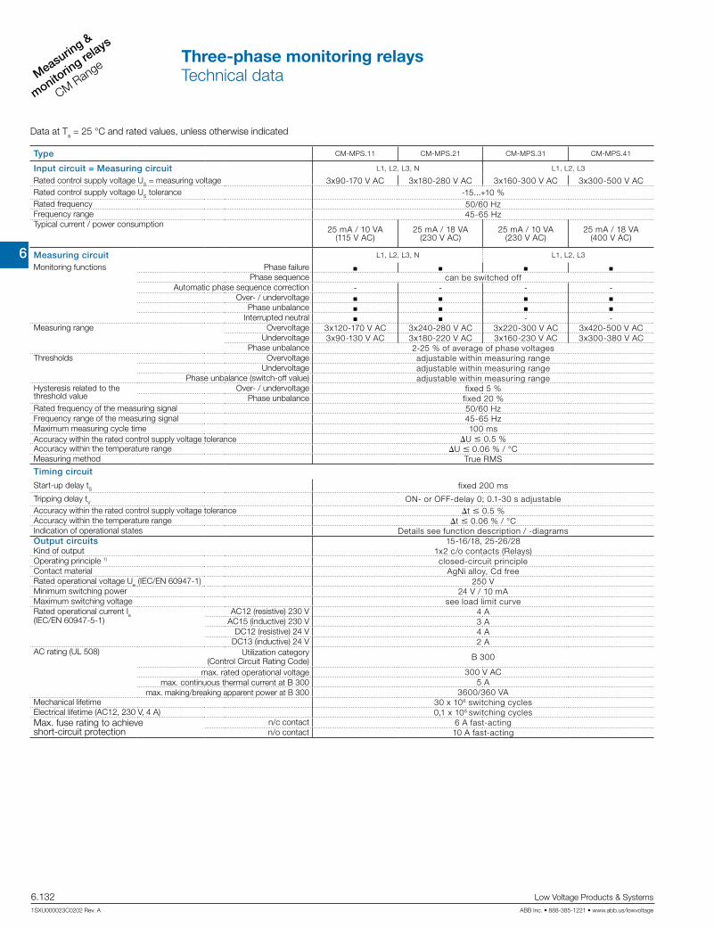
6
Measuring &
monitorin
g relays
CM Range
6.132 Low Voltage Products & Systems
1SXU000023C0202 Rev. A ABB Inc. • 888-385-1221 • www.abb.us/lowvoltage
Data at Ta = 25 °C and rated values, unless otherwise indicated
Type CM-MPS.11 CM-MPS.21 CM-MPS.31 CM-MPS.41
Input circuit = Measuring circuit L1, L2, L3, N L1, L2, L3
Rated control supply voltage US = measuring voltage 3x90-170 V AC 3x180-280 V AC 3x160-300 V AC 3x300-500 V ACRated control supply voltage US tolerance -15...+10 %Rated frequency 50/60 HzFrequency range 45-65 HzTypical current / power consumption
25 mA / 10 VA(115 V AC)
25 mA / 18 VA (230 V AC)
25 mA / 10 VA (230 V AC)
25 mA / 18 VA (400 V AC)
Measuring circuit L1, L2, L3, N L1, L2, L3
Monitoring functions Phase failure Phase sequence can be switched off
Automatic phase sequence correction - - - -Over- / undervoltage
Phase unbalance Interrupted neutral - -
Measuring range Overvoltage 3x120-170 V AC 3x240-280 V AC 3x220-300 V AC 3x420-500 V ACUndervoltage 3x90-130 V AC 3x180-220 V AC 3x160-230 V AC 3x300-380 V AC
Phase unbalance 2-25 % of average of phase voltagesThresholds Overvoltage adjustable within measuring range
Undervoltage adjustable within measuring rangePhase unbalance (switch-off value) adjustable within measuring range
Hysteresis related to the threshold value
Over- / undervoltage fixed 5 %Phase unbalance fixed 20 %
Rated frequency of the measuring signal 50/60 HzFrequency range of the measuring signal 45-65 HzMaximum measuring cycle time 100 msAccuracy within the rated control supply voltage tolerance U m 0.5 %Accuracy within the temperature range U m 0.06 % / °CMeasuring method True RMS
Timing circuit
Start-up delay tS fixed 200 ms
Tripping delay tV ON- or OFF-delay 0; 0.1-30 s adjustableAccuracy within the rated control supply voltage tolerance t m 0.5 %Accuracy within the temperature range t m 0.06 % / °CIndication of operational states Details see function description / -diagramsOutput circuits 15-16/18, 25-26/28Kind of output 1x2 c/o contacts (Relays)Operating principle 1) closed-circuit principleContact material AgNi alloy, Cd freeRated operational voltage Ue (IEC/EN 60947-1) 250 VMinimum switching power 24 V / 10 mAMaximum switching voltage see load limit curveRated operational current Ie (IEC/EN 60947-5-1)
AC12 (resistive) 230 V 4 AAC15 (inductive) 230 V 3 A
DC12 (resistive) 24 V 4 ADC13 (inductive) 24 V 2 A
AC rating (UL 508) Utilization category (Control Circuit Rating Code) B 300
max. rated operational voltage 300 V ACmax. continuous thermal current at B 300 5 A
max. making/breaking apparent power at B 300 3600/360 VAMechanical lifetime 30 x 106 switching cyclesElectrical lifetime (AC12, 230 V, 4 A) 0,1 x 10⁶ switching cyclesMax. fuse rating to achieve short-circuit protection
n/c contact 6 A fast-actingn/o contact 10 A fast-acting
Three-phase monitoring relaysTechnical data

6
Measuring &
monitoring relays
CM Range
Low Voltage Products & Systems 6.133ABB Inc. • 888-385-1221 • www.abb.us/lowvoltage 1SXU000023C0202 Rev. A
Data at Ta = 25 °C and rated values, unless otherwise indicated
Type CM-MPS.11 CM-MPS.21 CM-MPS.31 CM-MPS.41
General data 2)
MTBF on requestDuty time 100%Dimensions
(W x H x D)
product dimensions 22.5 x 85.6 x 103.7 mm (0.89 x 3.37 x 4.08 in)packaging dimensions 97 x 109 x 30 mm (3.82 x 4.29 x 1.18 in)
Weight Screw connection technology Easy Connect Technology (Push-in)
net weight depending on device, see ordering details
gross weight depending on device, see ordering detailsMounting DIN rail (IEC/EN 60715),
snap-on mounting without any toolMounting position anyMinimum distance to other units vertical / horizontal not necessary / not necessaryMaterial of housing UL 94 V-0Degree of protection housing / terminals IP50 / IP20Electrical connection 2)
Wire size Screw connection technology Easy Connect Technology (Push-in)
fine-strand with(out) wire end ferrule 1 x 0.5-2.5 mm2 (1 x 20-14 AWG)2 x 0.5-1.5 mm2 (2 x 20-16 AWG)
2 x 0.5-1.5 mm2 (2 x 20-16 AWG)
rigid 1 x 0.5-4 mm2 (1 x 20-12 AWG)2 x 0.5-2.5 mm2 (2 x 20-14 AWG)
2 x 0.5-1.5 mm2 (2 x 20-16 AWG)
Stripping length 8 mm (0.32 in)Tightening torque 0.6-0.8 Nm (5.31-7.08 lb.in) -Environmental dataAmbient temperature ranges operation / storage -25...+60 °C / -40...+85 °C
Damp heat (IEC 60068-2-30) 55 °C, 6 cycles
Climatic category 3K3
Vibration (sinusoidal) (IEC/EN 60255-21-1) Class 2
Shock (IEC/EN 60255-21-2) Class 2
Isolation data 2)
Rated insulation voltage Ui input circuit / output circuit 600 V
output circuit 1 / output circuit 2 300 V
Rated impulse withstand voltage Uimp (VDE 0110, IEC/EN 60664)
input circuit 6 kV; 1.2/50 µs
output circuit 4 kV; 1.2/50 µs
Test voltage between all isolated circuits (type test) 2.5 kV, 50 Hz, 1 s
Basis isolation input circuit / output circuit 600 V
Protective separation (VDE 0106 part 101 and 101/A, IEC/EN 61140)
input circuit / output circuit yes -
Pollution degree (VDE 0110, IEC/EN 60664) 3
Overvoltage category (VDE 0110, IEC 60664) III
Standards 2)
Product standard IEC/EN 60255-6, EN 50178
Low Voltage Directive 2006/95/EG
EMC directive 2004/108/EG
RoHS directive 2002/95/EG
Electromagnetic compatibilityInterference immunity to EN 61000-6-1, EN 61000-6-2
electrostatic discharge IEC/EN 61000-4-2 Level 3 (6 kV / 8 kV)
radiated, radio-frequency, electromagnetic field
IEC/EN 61000-4-3 Level 3 (10 V/m)
electrical fast transient / burst IEC/EN 61000-4-4 Level 3 (2 kV / 2 kHz)
surge IEC/EN 61000-4-5 Level 4 (2 kV L-L)
conducted disturbances,induced by radio-frequency fields
IEC/EN 61000-4-6 Level 3 (10 V)
harmonics and interharmonics IEC/EN 61000-4-13 Class 3
Interference emission EN 61000-6-3, EN 61000-6-4
high-frequency radiated IEC/CISPR 22, EN 50022 Class B
high-frequency conducted IEC/CISPR 22, EN 50022 Class B
1) Closed-circuit principle: Output relay(s) de-energize(s) if measured value exceeds or falls below the adjusted threshold value2) Data for devices 1SVR 730 xxx xxx, 1SVR 740 xxx xxx, 1SVR 750 xxx xxx, 1SVR 760 xxx xxx. For devices 1SVR x30 xxx xxx , 1SVR x50 xxx xxx refer to the data sheet.
Three-phase monitoring relaysTechnical data

6
Measuring &
monitorin
g relays
CM Range
6.134 Low Voltage Products & Systems
1SXU000023C0202 Rev. A ABB Inc. • 888-385-1221 • www.abb.us/lowvoltage
Data at Ta = 25 °C and rated values, unless otherwise indicated
Type CM-MPS.23 CM-MPS.43 CM-MPN.52 CM-MPN.62 CM-MPN.72
Input circuit = Measuring circuit L1, L2, L3, N L1, L2, L3
Rated control supply voltage US = measuring voltage 3x180-280 V AC 3x300-500 V AC 3x350-580 V AC 3x450-720 V AC 3x530-820 V AC
Rated control supply voltage US tolerance -15...+10 %Rated frequency 50/60/400 Hz 50/60 HzFrequency range 45-440 Hz 45-65 HzTypical current / power consumption 5 mA / 4 VA
(230 V AC)5 mA / 4 VA (400 V AC)
29 mA / 41 VA (480 V AC)
29 mA / 52 VA (600 V AC)
29 mA / 59 VA (690 V AC)
Measuring circuit L1, L2, L3, N L1, L2, L3
Monitoring functions Phase failure Phase sequence can be switched off
Automatic phase sequence correction configurableOver- / undervoltage
Phase unbalance Interrupted neutral - - - -
Measuring range Overvoltage 3x240-280 V AC 3x420-500 V AC 3x480-580 V AC 3x600-720 V AC 3x690-820 V ACUndervoltage 3x180-220 V AC 3x300-380
V AC 3x350-460 V AC 3x450-570 V AC 3x530-660 V AC
Phase unbalance 2-25 % of average of phase voltagesThresholds Overvoltage adjustable within measuring range
Undervoltage adjustable within measuring rangePhase unbalance (switch-off value) adjustable within measuring range
Hysteresis related to the threshold value
Over- / undervoltage fixed 5 %Phase unbalance fixed 20 %
Rated frequency of the measuring signal 50/60/400 Hz 50/60 HzFrequency range of the measuring signal 45-440 Hz 45-65 HzMaximum measuring cycle time 100 msAccuracy within the rated control supply voltage tolerance U m 0.5 %Accuracy within the temperature range U m 0.06 % / °CMeasuring method True RMSTiming circuitStart-up delay tS and tS2 fixed 200 ms
Start-up delay tS1 fixed 250 msTripping delay tV ON- or OFF-delay
0; 0.1-30 s adjustableON-delay
0; 0.1-30 s adjustableAccuracy within the rated control supply voltage tolerance t m 0.5 %Accuracy within the temperature range t m 0.06 % / °CIndication of operational states Details see function description / -diagramsOutput circuits 15-16/18, 25-26/28
Kind of output 2x1 or 1x2 c/o contacts configurable (Relays)Operating principle 1) closed-circuit principleContact material AgNi alloy, Cd freeRated operational voltage Ue IEC/EN 60947-1 250 VMinimum switching power 24 V / 10 mAMaximum switching voltage see load limit curveRated operational current Ie (IEC/EN 60947-5-1)
AC12 (resistive) 230 V 4 AAC15 (inductive) 230 V 3 A
DC12 (resistive) 24 V 4 ADC13 (inductive) 24 V 2 A
AC rating (UL 508)
Utilization category (Control Circuit Rating Code) B 300max. rated operational voltage 300 V AC
max. continuous thermal current at B 300 5 Amax. making/breaking apparent power at B 300 3600/360 VA
Mechanical lifetime 30 x 106 switching cyclesElectrical lifetime (AC12, 230 V, 4 A) 0,1 x 10⁶ switching cyclesMax. fuse rating to achieve short-circuit protection
n/c contact 6 A fast-acting 10 A fast-actingn/o contact 10 A fast-acting
1) Closed-circuit principle: Output relay(s) de-energize(s) if measured value exceeds or falls below the adjusted threshold value
Three-phase monitoring relaysTechnical data

6
Measuring &
monitoring relays
CM Range
Low Voltage Products & Systems 6.135ABB Inc. • 888-385-1221 • www.abb.us/lowvoltage 1SXU000023C0202 Rev. A
Data at Ta = 25 °C and rated values, unless otherwise indicated
Type CM-MPS.23 CM-MPS.43 CM-MPN.52 CM-MPN.62 CM-MPN.72
General data 2)
MTBF on requestDuty time 100%Dimensions (W x H x D) product dimensions 22.5 x 85.6 x 103.7 mm (0.89 x 3.37 x 4.08 in)
packaging dimensions 97 x 109 x 30 mm (3.82 x 4.29 x 1.18 in)Weight depending on device, see ordering detailsMounting DIN rail (IEC/EN 60715), snap-on mounting without any toolMounting position anyMinimum distance to other units vertical / horizontal not necessary / not necessaryMaterial of housing UL 94 V-0Degree of protection housing / terminals IP50 / IP20Electrical connection 2)
Wire size Screw connection technology Easy Connect Technology (Push-in)fine-strand with(out) wire end ferrule 1 x 0.5-2.5 mm2 (1 x 20-14 AWG)
2 x 0.5-1.5 mm2 (2 x 20-16 AWG)2 x 0.5-1.5 mm2 (2 x 20-16 AWG)
rigid 1 x 0.5-4 mm2 (1 x 20-12 AWG)2 x 0.5-2.5 mm2 (2 x 20-14 AWG)
2 x 0.5-1.5 mm2 (2 x 20-16 AWG)
Stripping length 8 mm (0.32 in)Tightening torque 0.6-0.8 Nm (5.31-7.08 lb.in) -Environmental dataAmbient temperature ranges operation / storage -25...+60 °C / -40...+85 °CDamp heat (IEC 60068-2-30) 55 °C, 6 cyclesClimatic category 3K3Vibration (sinusoidal) (IEC/EN 60255-21-1) Class 2Shock (IEC/EN 60255-21-2) Class 2Isolation data 2)
Rated insulation voltage Ui input circuit / output circuit 600 V 1000 Voutput circuit 1 / 2 300 V
Rated impulse withstand voltage Uimp (VDE 0110, IEC/EN 60664)
input circuit 6 kV; 1.2/50 µs 8 kV; 1.2/50 µsoutput circuit 4 kV; 1.2/50 µs
Test voltage (type test) between
isolated output circuits 2.5 kV, 50 Hz, 1 sinput circuit and isolated output circuits 2.5 kV, 50 Hz, 1 s 4 kV, 50 Hz, 1 s
Basis isolation input circuit / output circuit 600 V 1000 VProtective separation(VDE 0106 part 101 and 101/A, IEC/EN 61140)
input circuit / output circuit -
Pollution degree (VDE 0110, IEC/EN 60664) 3Overvoltage category (VDE 0110, IEC 60664) IIIStandards 2)
Product standard IEC/EN 60255-6, EN 50178Low Voltage Directive 2006/95/EGEMC directive 2004/108/EGRoHS directive 2002/95/EGElectromagnetic compatibilityInterference immunity to EN 61000-6-1, EN 61000-6-2
electrostatic discharge IEC/EN 61000-4-2 Level 3 (6 kV / 8 kV)radiated, radio-frequency, electromagnetic field
IEC/EN 61000-4-3 Level 3 (10 V/m)
electrical fast transient / burst IEC/EN 61000-4-4 Level 3 (2 kV / 2 kHz)surge IEC/EN 61000-4-5 Level 4 (2 kV L-N) Level 4 (2 kV L-L)conducted disturbances,induced by radio-frequency fields
IEC/EN 61000-4-6 Level 3 (10 V)
harmonics and interharmonics IEC/EN 61000-4-13 Class 3Interference emission EN 61000-6-3, EN 61000-6-4
high-frequency radiated IEC/CISPR 22, EN 50022 Class Bhigh-frequency conducted IEC/CISPR 22, EN 50022 Class B
2) Data for devices 1SVR 730 xxx xxx, 1SVR 740 xxx xxx, 1SVR 750 xxx xxx, 1SVR 760 xxx xxx. For devices 1SVR x30 xxx xxx , 1SVR x50 xxx xxx refer to the data sheet.
Three-phase monitoring relaysTechnical data

6
Measuring &
monitorin
g relays
CM Range
6.136 Low Voltage Products & Systems
1SXU000023C0202 Rev. A ABB Inc. • 888-385-1221 • www.abb.us/lowvoltage
Data at Ta = 25 °C and rated values, unless otherwise indicated
Type CM-UFS.2
Input circuit - Measuring circuit L1, L2, L3 L-N
Rated control supply voltage US = measuring voltage 3 x 400 V AC 3 x 230 V AC
Rated control supply voltage tolerance US -20...+20 %Control supply voltage range 3 x 300-500 V AC 3 x 180-280 V ACRated frequency 50 HzFrequency range 45-55 HzTypical current / power consumption 23 mA / 16 VAPower failure buffering time min. 20 msInput circuit - measuring circuit L1, L2, L3 L-N
Monitoring functions Phase failure Over-/ undervoltage
Over-/ underfrequency 10 minutes average value –
Measuring range Voltage range 3 x 320-480 V AC 3 x 184-276 V ACFrequency range 45-55 Hz
Thresholds Overvoltage fix, 120 % of UsUndervoltage fix, 80 % of Us
Overfrequency 50,3 or 51 Hz, configurableUnderfrequency 49,7 or 49 Hz, configurable
10 minutes average value –Hysteresis related to thethreshold value
Over-/ undervoltage fix 5 %Over-/ underfrequency fix 20 mHz
Rated frequency of the measuring signal 50 HzFrequency range of the measuring signal 45-55 HzMaximum measuring cycle time 50 msMaximum reaction time (time between faultdetection and change of switching status of the relay)
Over-/ undervoltage < 120 msOver-/ underfrequency < 100 ms
10 minutes average value –Accuracy within the rated control supply voltage tolerance U m 0,5 %Accuracy within the temperature range U m 0,06 % / °CMeasuring method True RMSTiming circuitStart-up delay tS1 prior to grid connection after a short interruption fix, 1 s
Restart delay tS2 adjustable, 0 s; 0,1 – 30 sAccuracy within the rated control supply voltage tolerance t m 0,5 %Accuracy within the temperature range t m 0,06 % / °C
Indication of operational states 1 yellow LED, 2 red LEDsDetails see operation mode and function description/diagrams
Output circuits 15-16/18, 25-26/28Kind of output Relais, 1 x 2 changeoverOperation principle 1) closed-circuit principleContact material AgNi alloy, Cd freeRated operational voltage Ue (IEC/EN 60947-1) 250 VMinimum switching voltage / switching current 24 V / 10 mAMaximum switching voltage / switching current see load limit curveRated operational current Ie (IEC/EN 60947-5-1)
AC12 (resistive) 230 V 4 AAC15 (inductive) 230 V 3 A
DC12 (resistive) 24 V 4 ADC13 (inductive) 24 V 2 A
Mechanical lifetime 30 x 106 switching cyclesElectrical lifetime (AC12, 230 V, 4 A) 0,1 x 10⁶ switching cyclesMax. fuse rating to achieve short-circuit protection
n/c contact 6 A fast-actingn/o contact 10 A fast-acting
Three-phase monitoring relaysTechnical data

6
Measuring &
monitoring relays
CM Range
Low Voltage Products & Systems 6.137ABB Inc. • 888-385-1221 • www.abb.us/lowvoltage 1SXU000023C0202 Rev. A
Data at Ta = 25 °C and rated values, unless otherwise indicated
Type CM-UFS.2
General dataMTBF on requestDuty time 100%Dimensions (W x H x D) product dimensions 22.5 x 78 x 100 mm (0.89 x 3.07 x 3.94 in)Weight gross weight 0.140 (0.31)Mounting DIN rail (IEC/EN 60715), snap-on mounting without any toolMounting position anyMinimum distance to other units vertical / horizontal not necessary / not necessaryDegree of protection housing / terminals IP50 / IP20Electrical connectionWire size fine-strand with(out) wire end ferrule 2 x 0.75 - 2.5 mm² (2 x 18-14 AWG)
rigid 2 x 0.5 - 4 mm² (2 x 20-12 AWG)Stripping length 7 mm (0.28 in)Tightening torque 0.6-0.8 Nm (5.31-7.08 lb.in)Environmental dataAmbient temperature range operation / storage -25...+60 °C / -40...+85 °CDamp heat, cyclic (IEC/EN 60068-2-30) 2 x 12 h cycle, 55 °C, 95 % RHClimatic category (IEC/EN 60721-3-1) 3K3Vibration (sinusoidal) (IEC/EN 60255-21-1) Class 2Shock (IEC/EN 60255-21-2) Class 2Isolation dataRated impulse withstand voltage Ui input circuit / output circuit 600 V
output circuit 1 / 2 300 VRated impulse withstand voltage Uimp (VDE 0110, IEC/EN 60664)
input circuit 6 kV; 1.2/50 µsoutput circuit 4 kV; 1.2/50 µs
Test voltage between all isolated circuits (type test) 2.5 kV, 50 Hz, 1 sBasis isolation input circuit / output circuit 600 VProtective separation (VDE 0160 Part 101 and 101/A, IEC/EN 61140)
input circuit / output circuityes
Pollution degree (VDE 0110, IEC/EN 60664) 3Overvoltage category (VDE 0110, IEC 60664) IIIStandards
Product standard Type-tested in accordance with the "Guideline for Connections to ENEL distribution network" Ed.2.1., January 2011
Further standards EN 50178, EN 61727Low Voltage Directive 2006/95/EGEMV-Directive 2004/108/EGRoHS-Directive 2002/95/EGElectromagnetic compatibilityInterference immunity to IEC/EN 61000-6-1, IEC/EN 61000-6-2
electrostatic discharge IEC/EN 61000-4-2 Level 3 (6 kV / 8 kV)radiated, radio-frequency, electromagnetic field
IEC/EN 61000-4-3 Level 3 (10 V/m)
electrical fast transient / burst IEC/EN 61000-4-4 Level 3 (2 kV / 2 kHz)surge IEC/EN 61000-4-5 Level 4 (2 kV L-L, L-N)conducted disturbances,induced by radio-frequency fields
IEC/EN 61000-4-6 Level 3 (10 V)
harmonics and interharmonics IEC/EN 61000-4-13 Class 3Interference emission IEC/EN 61000-6-3, IEC/EN 61000-6-4
high-frequency radiated IEC/CISPR 22, EN 50022 Class Bhigh-frequency conducted IEC/CISPR 22, EN 50022 Class B
1) Closed-circuit principle: Output relay(s) de-energize(s) if measured value exceeds or falls below the adjusted threshold value
Three-phase monitoring relaysTechnical data

6
Measuring &
monitorin
g relays
CM Range
6.138 Low Voltage Products & Systems
1SXU000023C0202 Rev. A ABB Inc. • 888-385-1221 • www.abb.us/lowvoltage
Notes
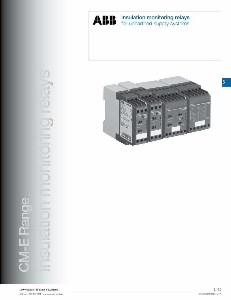
6
Measuring &
monitoring relays
CM Range
Low Voltage Products & Systems 6.139ABB Inc. • 888-385-1221 • www.abb.us/lowvoltage 1SXU000023C0202 Rev. A
Insulation monitoring relaysfor unearthed supply systems
Insu
latio
n m
onito
ring
rela
ysC
M-E
Ran
ge

6
Measuring &
monitorin
g relays
CM Range
6.140 Low Voltage Products & Systems
1SXU000023C0202 Rev. A ABB Inc. • 888-385-1221 • www.abb.us/lowvoltage
Insulation monitoring relays for unearthed pure AC systems:
Characteristics
• For monitoring the insulation resistance of unearthed IT system: up to Un = 400 V AC
• According to IEC/EN 61227-8 "Electrical safety in low voltage distribution systems up to 1000 V AC and 1500 V DC – Equipment for testing, measuring o der monitoring of protective measures – Part 8: Insulation monitoring devices for IT systems"
• Rated control supply voltage 24–240 V AC/DC• Superimposed DC signal• One measuring range 1–100 kW• Precise adjustment of the threshold value in 1 kW steps• Interrupted wire detection• Fault storage/latching configurable by control input• 1 c/o contact, closed-circuit principle• 22.5 mm [0.89 in] width• 3 LEDs for status indication
• For monitoring the insulation resistance of unearthed IT systems up to Un= 250 V AC and 300 V DC or Un= 400 V AC and 600 V DC
• According to IEC/EN 61227-8 "Electrical safety in low voltage distribution systems up to 1000 V AC and 1500 V DC – Equipment for testing, measuring oder monitoring of protective measures – Part 8: Insulation monitoring devices for IT systems"
• Rated control supply voltage 24-240 V AC/DC• Prognostic measuring principle with superimposed square
wave signal• 1 or 2 measuring ranges (1-100kW or 1-100 kW + 2-200 kOhm)1)
• 1 or 2 (configurable) c/o contacts1)
• Precise adjustment of the measuring value in 1 or 2 kW steps1)
• (non-volatile) fault storage, configurable latching, interrupted wire protection, open- or closed-circuit principle selectable1)
• 22.5 or 45 mm width• 3 LEDs for status indication• Solution for solar available
Standardization background:
EC/EN 61557-1 "Electrical safety in low voltage distribution system up to 1000 V AC and 1500 V DC – Equipment for testing, mea-suring or monitoring of protective measures – Part 1: General requirements"
IEC/EN 61557-8 "Electrical safety in low voltage distribution system up to 1000 V AC and 1500 V DC – Equipment for testing, mea-suring or monitoring of protective measures – Part 1: Insulation monitoring devices for IT systems"
A new generation of insulation monitoring relays of the CM range
consolidates ABB’s strengths in innovative control products.
The new products are in accordance to IEC/EN 61557-1 and to IEC/EN 61557-8. That means the monitoring relays can be used directly to measure the insulation resistance in unearthed AC and DC mains with a volt-age up to 690 V AC and 1000 V DC!
With the new prognostic measuring principle the measuring and response time is reduced significantly.
1) depending on device
Insulation monitoring relays for unearthed AC, DC
or mixed AC/DC systems:
Characteristics
Insulation monitoring relays for unearthed supply systemsBenefits and advantages

6
Measuring &
monitoring relays
CM Range
Low Voltage Products & Systems 6.141ABB Inc. • 888-385-1221 • www.abb.us/lowvoltage 1SXU000023C0202 Rev. A
In electricity supply systems, an earthing system defines the
electrical potential of the conductors relative to that of the
earth’s conductive surface. The choice of earthing system has
implications for the safety and electromagnetic compatibility of
the power supply. Note that regulations for earthing (grounding)
systems vary considerably among different countries.
The international standard IEC 60364 distinguishes three families of earth-
ing arrangements, using the two-letter codes TN,
TT and IT.
The first letter indicates the connection between earth and the power-sup-
ply equipment (generator or transformer):
T: direct connection of a point with earth (Latin: terra)
I: no point is connected with earth (insulation),
except perhaps via a high impendance
The second letter indicates the connection between earth and the electri-
cal device being supplied:
T: direct connection of a point with earth
N: direct connection to neutral at the origin of installation,
which is connected to the earth
IT supply systems
The IT system is supplied either by an isolation transformer or
a voltage source, such as battery or a generator.
In this system no active conductor is directly connected to earth potential.
The advantage of this is that only a small fault current can flow in case of
an insulation fault. This current is essentially caused by the system's leak-
age capacitance.
The systems's fuse or MCB does not respond, thus maintaining the volt-
age supply and therefore operation even in case of a phase-to-earth fault.
The high reliability of an IT system is guaranteed thanks to continous insu-
lation monitoring.
The insulation monitoring device recognizes insulation faults as they
develop, and immediately reports that the value has fallen below the mini-
mum. This prevents operational interruptions caused by a second more
severe insulation fault.
L1
L2
L3
N
PE
M
A1 11 S2 S321 S1
L+ V12 14A2V1-V1+
22 24 L- K
Consumer3~
w
CM-IWN.1
Insulation monitoring relays for unearthed supply systemsInsulation monitoring in IT systems
6
Measuring &
monitorin
g relays
CM Range
6.142 Low Voltage Products & Systems
1SXU000023C0202 Rev. A ABB Inc. • 888-385-1221 • www.abb.us/lowvoltage
Application / monitoring function CM-IWS.2 The CM-IWS.2 serves to monitor insulation resistance in accordance with IEC 61557-8 in unearthed IT AC systems. The insulation resistance be-tween system lines and system earth is measured. If this falls below the adjustable threshold values, the output relay de-energizes. The device can monitor control circuits (single-phase) and main circuits (3-phase). Supply systems with voltages Un = 0-400 V AC (45-65 Hz) can be directly con-nected to the measuring inputs and their insulation resistance being monitored. For systems with voltages above 400 V AC the insulation monitoring relay CM-IWN.1 with or without the coupling unit CM-IVN can be used.
Measuring principle CM-IWS.2 A superimposed DC measuring signal is used for measurement. From the superimposed DC measuring voltage and its resultant current the value of the insulation resistance of the system to be monitored is calculated.
Application / monitoring function CM-IWS.1 The CM-IWS.1 serves to monitor insulation resistance in accordance with IEC 61557-8 in unearthed IT AC systems, IT AC systems with galvanically connected DC circuits, or unearthed IT DC systems. The insulation resis-tance between system lines and system earth is measured. If this falls be-low the adjustable threshold value, the output relay de-energizes. The de-vice can monitor control circuits (single-phase) and main circuits (3-phase). Supply systems with voltages Un = 0-250 V AC (15-400 Hz) or 0-300 V DC can be directly connected to the measuring inputs and their insulation resistance being monitored. For systems with voltages above 250 V AC and 300 V DC the insulation monitoring relay CM-IWN.x with or without the coupling unit CM-IVN can be used.
Measuring principle CM-IWS.1 A pulsating measuring signal is fed into the system to be monitored and the insula-tion resistance calculated. This pulsating measuring signal alters its form depending on the insulation resistance and system leakage capacitance. From this altered form the change in the insulation resistance is forecast. When the forecast insulation resis-tance corresponds to the insulation resistance calculated in the next measurement cycle and is smaller than the set threshold value, the output relay de-energizes. This measuring principle is also suitable for the detection of symmetrical insulation faults.
Application / monitoring function CM-IWN.1 / CM-IWN.5 The CM-IWN.x serves to monitor insulation resistance in accordance with IEC 61557-8 in unearthed IT AC systems, IT AC systems with galvani-cally connected DC circuits, or unearthed IT DC systems. The insulation resistance between system lines and system earth is measured. If this falls below the adjustable threshold values, the output relays switch into the fault state. The device can monitor control circuits (single-phase) and main circuits (3-phase). Supply systems with voltages Un = 0-400 V AC (15-400 Hz) or 0-600 V DC can be directly connected to the measuring inputs and their insulation resistance being monitored. For systems with voltages above 400 V AC and 600 V DC the coupling unit CM-IVN can be used for the expansion of the CM-IWN.x voltage range.
Measuring principle CM-IWN.1 / CM-IWN.5 A pulsating measuring signal is fed into the system to be monitored and the insulation resistance calculated.This pulsating measuring signal alters its form depending on the insulation resistance and system leakage capacitance. From this altered form the change in the insulation resistance is forecast. When the forecast insulation resistance corresponds to the insulation resistance calculated in the next measurement cycle and is smaller than the set threshold value, the output relays are acti-vated or deactivated, depending on the device configuration. This measuring principle is also suitable for the detection of symmetrical insulation faults.
Application / monitoring function CM-IVN The coupling unit CM-IVN is designed to extend the nominal voltage range of the insulation monitoring relay CM-IWN.1 up to 690 V AC and 1000 V DC. The coupling unit can be connected to the system to be monitored by
means of the terminals VL+ and VL-. The terminal Vw has to be connected to the earth potential. The terminals L+, V1+, L-, V1-, VS and VE have to be connected to the CM-IWN.1 as shown in the connection diagrams be-low. Supply systems with voltages Un = 0-690 V AC (15-400 Hz) or 0-1000 V DC can be connected.
Measuring principle CM-IVN With CM-IWN.1 a pulsating measuring signal is fed into the system to be monitored and the insulation resistance calculated. This pulsating mea-suring signal alters its form depending on the insulation resistance and system leakage capacitance. From this altered form the change in the insulation resistance is forecast. When the forecast insulation resistance corresponds to the insulation resistance calculated in the next measure-ment cycle and is smaller than the set threshold value, the output relays are activated or deactivated, depending on the device configuration. This measuring principle is also suitable for the detection of symmetrical insula-tion faults.
Insulation monitoring relays for unearthed supply systemsApplication / monitoring function, measuring principle

6
Measuring &
monitoring relays
CM Range
Low Voltage Products & Systems 6.143ABB Inc. • 888-385-1221 • www.abb.us/lowvoltage 1SXU000023C0202 Rev. A
For monitoring the insulation resistance of unearthed IT systems up to Un = 400 V AC Rated control supply voltage 24-240 V AC/DC Measuring principle with superimposed DC voltage One measuring range 1-100 kW Precise adjustment of the threshold value in 1 kW steps Fault storage / latching configurable by control input 1 c/o contact, closed-circuit principle 22.5 mm [0.89 in] width 3 LEDs for status indication
Characteristics CM-IWS.2
Characteristics CM-IWS.1
Characteristics CM-IWN.1, CM-IWN.5
Characteristics CM-IVN
For monitoring the insulation resistance of unearthed IT systems up to Un = 250 V AC and 300 V DC Rated control supply voltage 24-240 V AC/DC Prognostic measuring principle with superimposed square wave signal One measuring range 1-100 kW Precise adjustment of the threshold value in 1 kW steps Interrupted wire detection Fault storage / latching configurable by control input 1 c/o [SPDT] contact, closed-circuit principle 22.5 mm [0.89 in] width 3 LEDs for status indication
For monitoring the insulation resistance of unearthed IT systems up to Un = 400 V AC and 600 V DC CM-IWN.5: According to IEC/EN 61557-8 “Electrical safety in low voltage distribution systems up to 1000 V a.c. and 1500 V d.c. – Equipment for
testing, measuring or monitoring of protective measures – Part 8: Insulation monitoring devices for IT systems" Rated control supply voltage 24-240 V AC/DC Prognostic measuring principle with superimposed square wave signal Two measuring ranges 1-100 kΩ and 2-200 kΩ One (1 x 2 c/o) or two (2 x 1 c/o) threshold values Ran1/R11) (final switch-off) and Ran2/R21) (prewarning) configurable2)
Precise adjustment of the threshold values in 1 kΩ steps (R1) and 2 kΩ steps (R2) Interrupted wire detection configurable Non-volatile fault storage configurable Open- or closed-circuit principle configurable 45 mm (1.77 in) width 3 LEDs for status indication
1) term. acc. to IEC/EN 61557-8 2) R2 only active with 2 x 1 c/o configuration
Expansion of the nominal voltage range of the insulation monitoring relay CM-IWN.1 for monitoring the insulation resistance of unearthed IT systems up to 690 V AC and 1000 V DC
According to IEC/EN 61557-8 “Electrical safety in low voltage distribution systems up to 1000 V AC and 1500 V DC – Equipment for testing, measuring or monitoring of protective measures – Part 8: Insulation monitoring devices for IT systems"
Passive device, no supply voltage needed 45 mm [1.77 in] width
Insulation monitoring relays for unearthed supply systemsCharacteristics

6
Measuring &
monitorin
g relays
CM Range
6.144 Low Voltage Products & Systems
1SXU000023C0202 Rev. A ABB Inc. • 888-385-1221 • www.abb.us/lowvoltage
Typical applications
Benefits of ABB’s new range of insulation monitoring relays:
•ExtendedmeasuringvoltagerangeACandDC
•Alldeviceswithwidesupplyvoltagerange
•Reducednumberofreferences
•Optimizedsolutionsforsolarapplications
Cat
alo
g n
um
ber
1SV
R63
0670
R02
00
1SV
R63
0660
R01
00
1SV
R65
0660
R02
00
1SV
R65
0660
R03
00
1SV
R65
0660
R04
00
1SV
R65
0660
R05
00
1SV
R65
0669
R94
00
Ref
eren
ceco
de
CM
-IW
S.2
CM
-IW
S.1
CM
-IW
N.1
CM
-IW
N.4
CM
-IW
N.5
CM
-IW
N.6
CM
-IV
N
Rated control supply voltage Us
24 - 240 VAC/DC
Measuring voltages
250 V AC (L-PE) 400 V AC (L-PE) 690 V AC 300 V DC (L-PE) 600 V DC (L-PE) 1000 V DC Measuring range
1 - 100 kΩ 2 - 200 kΩ Output contacts
1 c/o 1 x 2 c/o or 2 x 1 c/o Working principle
open circuit principle open or closed principle adjustable Test
Front face button or control input Reset
Front face button or control input Fault storage / latching configurable Non voltage storage configurable Interrupted wire detection Threshold values configurable 1 1 2 2 2 2
System leakage capacitance, max.
10 μF 20 μF 500 μF 1000 μF 2000 μF
Coupling unit
Yes
Yes
Yes
Yes
CM
-IW
N.1
-6
Insulation monitoring relays for unearthed supply systemsSelection and conversion table
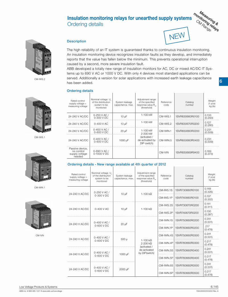
6
Measuring &
monitoring relays
CM Range
Low Voltage Products & Systems 6.145ABB Inc. • 888-385-1221 • www.abb.us/lowvoltage 1SXU000023C0202 Rev. A
Description
The high reliability of an IT system is guaranteed thanks to continuous insulation monitoring. An insulation monitoring device recognizes insulation faults as they develop, and immediately reports that the value has fallen below the minimum. This prevents operational interruption caused by a second, more severe insulation fault. ABB developed a totally new range of insulation monitors for AC, DC or mixed AC/DC IT Sys-tems up to 690 V AC or 1000 V DC. With only 4 devices most standard applications can be served. Additionally a version for solar applications with increased earth leakage capacitance has been added.
Ordering details
Rated control supply voltage =
measuring voltage
Nominal voltage Un of the distribution
system to be monitored
System leakage capacitance, max.
Adjustment range of the specified
response value Ran (threshold)
Referencecode
Catalognumber
Weight(1 pce) kg (lb)
24-240 V AC/DC 0-250 V AC /0-300 V DC 10 µF
1-100 kW CM-IWS.1 1SVR630660R0100 0.133
(0.293)
24-240 V AC/DC 0-400 V AC 10 µF1-100 kW
CM-IWS.2 1SVR630670R0200 0.127 (0.280)
24-240 V AC/DC 0-400 V AC / 0-600 V DC 20 µF 1-100 kW
2-200 kW (activated /
de-activated by DIP-switch)
CM-IWN.1 1SVR650660R0200 0.231 (0.509)
24-240 V AC/DC 0-400 V AC / 0-600 V DC 1000 µF CM-IWN.5 1SVR650660R0400 0.231
(0.509)
Passive device, no control
supply voltage needed
0-690 V AC / 0-1000 V DC CM-IVN 1SVR650669R9400 0.169
(0.373)
CM-IWS.2
CM-IWS.1
CM-IWN.1
CM-IVN
NEW
Insulation monitoring relays for unearthed supply systemsOrdering details
Ordering details - New range available at 4th quarter of 2012
Rated control supply voltage =
measuring voltage
Nominal voltage Un of the distribution
system to be monitored
System leakage capacitance, max.
Adjustment range of the specified
response value Ran (threshold)
Referencecode
Catalognumber
Weight(1 pce) kg (lb)
24-240 V AC/DC0-250 V AC /0-300 V DC
10 μF 1-100 kΩCM-IWS.1S 1SVR730660R0100 0.148
(0.326)
CM-IWS.1P 1SVR740660R0100 0.137(0.302)
24-240 V AC/DC 0-400 V AC 10 μF 1-100 kΩCM-IWS.2S 1SVR730670R0200 0.141
(0.311)
CM-IWS.2P 1SVR740670R0200 0.130(0.287)
24-240 V AC/DC0-400 V AC /0-600 V DC
20 μF
1-100 kΩ2-200 kΩ
(activated /de-activatedby DIPswitch)
CM-IWN.1S 1SVR750660R0200 0.241(0.531)
CM-IWN.1P 1SVR760660R0200 .217(0.478)
24-240 V AC/DC0-400 V AC /0-600 V DC
500 μCM-IWN.4S 1SVR750660R0300 0.241
(0.531)
CM-IWN.4P 1SVR760660R0300 0.217(0.478)
24-240 V AC/DC0-400 V AC /0-600 V DC
1000 μFCM-IWN.5S 1SVR750660R0400 0.241
(0.531)
CM-IWN.5P 1SVR760660R0400 0.217(0.478)
24-240 V AC/DC0-400 V AC /0-600 V DC
2000 μFCM-IWN.6S 1SVR760660R0500 0.241
(0.531)
CM-IWN.6P 1SVR760660R0500 0.217(0.478)

6
Measuring &
monitorin
g relays
CM Range
6.146 Low Voltage Products & Systems
1SXU000023C0202 Rev. A ABB Inc. • 888-385-1221 • www.abb.us/lowvoltage
1 ) The device has triggered after an insulation fault. The fault has been stored and the insula-tion resistance has returned to a higher value than the threshold value plus hysteresis.
2) Depending on the fault.
LEDs, status information and fault messages CM-IWS.2
1) The device has triggered after an insulation fault. The fault has been stored and the insu-lation resistance has returned to a higher value than the threshold value plus hysteresis.
2) Depending on the fault.
LEDs, status information and fault messages CM-IWS.1
1) Depending on the configuration
2) Possible faulty setting: The threshold value for final switch-off is set at a higher value than the threshold value for prewarning.
3) The device has triggered after an insulation fault. The fault has been stored and the insu-lation resistance has returned to a higher value than the threshold value plus hysteresis.
4) Depending on the fault
LEDs, status information and fault messages CM-IWN.1, CM-IWN.5
Insulation monitoring relays for unearthed supply systemsOperating state indication
Operational state LED U (green) LED F (red) LED R (yellow)Start-up W OFF OFFNo fault V OFF V
Insulation fault (below threshold value) V V OFFInvalid measuring result V T OFFInternal system fault OFF X OFFTest function X OFF OFFNo fault after fault storage1) V 2) X
Operational state LED U (green) LED F (red) LED R (yellow)Start-up W OFF OFFNo fault V OFF VInsulation fault (below threshold value) V V OFF
KE/w wire interruption V U OFF
System leakage capacitance too high /
invalid measurement resultV T OFF
Internal system fault OFF X OFFTest function X OFF OFFNo fault after fault storage1) V
2)X
Operational state LED U (green) LED F (red) LED R (yellow)Start-up W OFF OFFNo fault V OFF 1)Prewarning V W WInsulation fault (below threshold value) V V
1)
KE/w wire interruption V U1)
L+/L- wire interruption during system start-up
/ test functionW / X S
1)
System leakage capacitance too high /
invalid measurement resultV T
1)
Internal system fault 1)X
1)
Setting fault2)W W W
Test function X OFF 1)
No fault after fault storage3)V
4)X

6
Measuring &
monitoring relays
CM Range
Low Voltage Products & Systems 6.147ABB Inc. • 888-385-1221 • www.abb.us/lowvoltage 1SXU000023C0202 Rev. A
Connection diagram CM-IWS.2
A1S1 S2 S3
11
wLA2
w
A1
R < wA2
L
14 12
12 14
11
A1-A2S1-S3S2-S3L
w 11-12/14
Control supply voltageRemote testRemote resetMeasuring circuit/input, system connectionMeasuring circuit/input, earth connectionsOutput relay, closed-circuit principle
Connection diagram CM-IWS.1 Connection diagram CM-IWN.1
A1S1 S2 S3
KE11
wL-L+A2
KE wL-
A1
R < wA2
L+
14 12
12 14
11
A1-A2S1-S3S2-S3L+, L–
w, KE 11-12/14
Control supply voltageRemote testRemote resetMeasuring circuit/input, system connectionMeasuring circuit/input, earth connectionsOutput relay, closed-circuit principle
A1-A2S1-S3S2-S3L+, L–
w, KE VS, V1+, V1-11-12/1421-22/24
Control supply voltageRemote testRemote resetMeasuring circuit/input, system connectionMeasuring circuit/input, earth connectionsConnections for the coupling unit (if used)Output relay 1, open- or closed-circuit principleOutput relay 2, open- or closed-circuit principle
A1 11 S2 S321 S1
wL+ VS12 14
A2V1-V1+
KE wL-
A1
R < w
A2
L+
22 24 L- KE
12 14
11
22 24
21
ON OFF (default)
DIP switch 1
Operating principle of the output relays
Closed-circuit principle g
If closed-circuit principle is selected, the output relays de-energize in case a fault is occuring. In non-fault state the relays are energized.
Open-circuit principle h
If open-circuit principle is selected, the output relays energize in case a fault is occuring. In non-fault state the relays are de-energized.
DIP switch 2
Non-volatile fault storage
Fault storage activated (latching) f
If the fault storage function is activated, the output relays remain in tripped position until a reset is done either by the front-face button or by the remote reset connection S2-S3. This function is non-volatile.
Fault storage de-activated (non latching) e
If the fault storage function is de-activated, the output relays switch back to their original position as soon as the insulation fault no longer exists.
DIP switch 3
Interrupted wire detection
Interrupted wire detection activated u
With this configuration, the CM-IWN.1 monitoring relays the wires connected to w and KE for interruptions.
Interrupted wire detection de-activated v With this configuration the inter-rupted wire detection is de-activated.
DIP switch 4
2 x 1 c/o, 1 x 2 c/o
2 x 1 c/o (SPDT) contact i
If operating principle 2 x 1 c/o contact is selected, the output relay R1 (11-12/14) reacts to threshold value R1 (final switch-off) and the output relay R2 (21-22/24) reacts to threshold value R2 (prewarning)
1 x 2 c/o (SPDT) contacts j
If operating principle 1 x 2 c/o contacts is selected, both output relays R1 (11-12/14) and R2 (21-22/24) react synchronously to threshold value R1. Settings of the threshold value R2 have no effect on the operation.
Position 4 123
ON
OFF
i u f ghevj
DIP switches of IWN.1
Connection diagram CM-IVN
A1 11 S2 S321 S1
wL+ VS12 14
A2V1-V1+
22 24 L- KE
VL+ VL-
VwL-L+VE
V1-V1+VS
L1
L2
L3
N
PE
CM-IVN CM-IWN.1
V1- Connection to CM-IWN.1 - V1-
VL+, VL- Measuring circuit / Measuring inputConnection to the system
Vw Measuring circuit / Measuring inputConnection to earth
VE Connection to CM-IWN.1 - w
VS Connection to CM-IWN.1 - VS
L+ Connection to CM-IWN.1 - L+
V1+ Connection to CM-IWN.1 - V1+
L- Connection to CM-IWN.1 - L-
Insulation monitoring relays for unearthed supply systemsConnection diagrams, DIP switches

6
Measuring &
monitorin
g relays
CM Range
6.148 Low Voltage Products & Systems
1SXU000023C0202 Rev. A ABB Inc. • 888-385-1221 • www.abb.us/lowvoltage
*in combination with CM-IVN ±1.5 kW
Data at Ta = 25 °C and rated values, unless otherwise indicated
CM-IWS.2 CM-IWS.1 CM-IWN.1,4,5,6Input circuit - Supply circuit A1 - A2Rated control supply voltage Us 24-240 V AC/DCRated control supply voltage tolerance -15...+10 %Typical current / power consumption 24 V DC 30 mA / 0.7 VA 35 mA / 0.9 VA 55 mA / 1.3 VA
115 V AC 12 mA / 1.4 VA 17 mA / 2.0 VA 20 mA / 2.3 VA230 V AC 12 mA / 2.8 VA 14 mA / 3.2 VA 15 mA / 3.5 VA
Rated frequency fs DC or 15-400 HzFrequency range AC 13.5-440 HzPower failure buffering time min. 20 msInput circuit - Measuring circuit L, w L+, L-, w, KE L+, L-, w, KEMonitoring function insulation resistance monitoring of IT systems (IEC/EN 61557-8)Measuring principle superimposed DC
voltageprognostic measuring principle with superimposed square wave signal
Nominal voltage Un of the distribution system to be monitored 0-400 V AC 0-250 V AC / 0-300 V DC
400 V AC / 0-600 V DC
Voltage range of the distribution system to be monitored 0-460 V AC (tolerance +15 %)
0-287.5 V AC / 0-345 V DC
(tolerance +15 %)
0-460 V AC / 0-690 V DC
(tolerance +15 %)
Rated frequency fN of the distribution system to be monitored 50-60 Hz DC or 15-400 Hz DC or 15-400 HzSystem leakage capacitance Ce max. 10 µF CM-IWN.1 20 µF
CM-IWN.5 1000 µF
Tolerance of the rated frequency fN 45-65 Hz 13.5-440 Hz 13.5-440 HzExtraneous DC voltage Ufg (when connected to an AC system) max. none 290 V DC 460 V DCNumber of possible response / threshold values 1 2Adjustment range of the specified response value Ran (threshold) min.-max. 1-100 kW –
min.-max. R1 – 1-100 kWmin.-max. R2 – 2-200 kW
(activated / de-acti-vated by DIP-switch)
Adjustment resolution 1 kWR1 1 kW 1 kWR2 – 2 kW
Tolerance of the adjusted threshold value / Relative percentage uncertainty Aat -5...+45 °C, Un = 0-115 %, Us = 85-110 %, fN, fs, Ce = 1µF
at 1-10 kW RF ±0.5 kW –at 10-100 kW RF ±6 % –
at 1-15 kW RF – ±1 kW*at 15-200 kW RF – ±8 %
Hysteresis related to the threshold value 25 %; min. 2 kWInternal impedance Zi at 50 Hz 135 kW 100 kW 155 kWInternal DC resistance Ri 185 kW 115 kW 185 kWMeasuring voltage Um 15 V 22 V 24 VTolerance of measuring voltage Um +10 %Measuring current Im max. 0.1 mA 0.3 mA 0.15 mAResponse time tan
pure AC system 0.5 x Ran and Ce = 1 µF max. 10 sDC system or AC system with connected rectifiers – max. 15 sRepeat accuracy (constant parameters) < 0.1 % of full scaleAccuracy of Ra (measured value) within the rated control supply voltage tolerance < 0.05 % of full scale
Accuracy of Ra (measured value) within the operation temperature range
at 1-10 kW RF 5 W / Kat 10-100 kW RF 0.05 % / K –at 10-200 kW RF – 0.05 % / K
Transient over voltage protection (w - terminal) Z-diode avalanche diode
Input circuit - Control circuits S1 - S2 - S3
Control inputs - volt free S1-S3 remote testS2-S3 remote reset
Maximum switching current in the control circuit 1 mAMaximum cable length to the control inputs 50 m - 100 pF/m [164 ft - 30.5 pF/ft]Minimum control pulse length 150 msNo-load voltage at the control input ≤ 24 V ± 5 % ≤ 24 V DCIndication of operational statesControl supply voltage LED U (green)*Fault message LED F (red)*Relay status LED R (yellow)*
Insulation monitoring relays for unearthed supply systemsTechnical data

6
Measuring &
monitoring relays
CM Range
Low Voltage Products & Systems 6.149ABB Inc. • 888-385-1221 • www.abb.us/lowvoltage 1SXU000023C0202 Rev. A
CM-IWS.2 CM-IWS.1 CM-IWN.1,4,5,6
Output circuitsKind of output
relay, 1 c/o (SPDT) contact2 x 1 or 1 x 2 c/o (SPDT) contacts
configurableOperating principle
closed-circuit principle1)open- or closedcircuit principle1)
confi gurableContact material AgNi alloy, Cd freeRated voltage (VDE 0110, IEC 60947-1) 250 V AC / 300 V DCMin. switching voltage / Min. switching current 24 V / 10 mAMax. switching voltage / Max. switching current see data sheetRated operational current Ie(IEC/EN 60947-5-1)
AC12 (resistive) at 230 V 4 AAC15 (inductive) at 230 V 3 A
DC12 (resistive) at 24 V 4 ADC13 (inductive) at 24 V 2 A
AC rating (UL 508) Utilization category (Control Circuit Rating Code) B 300, pilot duty general purpose (250 V, 4 A, cos φ 0.75)
max. rated operational voltage 250 V ACmax. continuous thermal
current at B 300 4 A
max. making/breakingapparent power at B 300 3600/360 VA
Mechanical lifetime 30 x 106 switching cyclesElectrical lifetime (AC12, 230 V, 4 A) 0.1 x 10⁶ switching cyclesMax. fuse rating to achieve short-circuit protection n/c contact 6 A fast-acting
n/o contact 10 A fast-actingConventional thermal current Ith (IEC/EN 60947-1) 4 AGeneral dataDuty time 100 %Dimensions (W x H x D) 22.5 x 78 x 100 mm
[0.89 x 3.07 x 3.94 in]45 x 78 x 100 mm
[1.78 x 3.07 x 3.94 in]Weight gross weight 0.149 kg [0.328 lb] 0.163 kg [0.359 lb] 0.258 kg [0.569 lb]
net weight 0.127 kg [0.280 lb] 0.133 kg [0.293 lb] 0.231 kg [0.509 lb]Mounting DIN rail (EN 60715), snap-on mounting without any toolMounting position anyMinimum distance to other units vertical not necessary
horizontal 10 mm [0.4 in]at Un > 240 V not necessary 10 mm [0.4 in]
at Un > 400 VDegree of protection housing / terminal IP50 / IP20Electrical connectionWire size fine-strand with(out) wire end ferrule 2 x 0.75-2.5 mm² (2 x 18-14 AWG)
rigid 2 x 0.5-4 mm² (2 x 20-12 AWG)Stripping length 7 mm [0.28 in]Tightening torque 0.6-0.8 Nm [5.31-7.08 lb.in]Environmental dataAmbient temperature ranges operation/storage/ transport -25...+60 °C/-40...+85 °C/-40...+85 °CClimatic category IEC/EN 60721-3-3 3K5 (no condensation, no ice formation)Damp heat, cyclic IEC/EN 60068-2-30 6 x 24 h cycle, 55 °C, 95 % RHVibration, sinusoidal IEC/EN 60255-21-1 Class 2Shock, half-sine IEC/EN 60255-21-2 Class 2
Insulation monitoring relays for unearthed supply systemsTechnical data

6
Measuring &
monitorin
g relays
CM Range
6.150 Low Voltage Products & Systems
1SXU000023C0202 Rev. A ABB Inc. • 888-385-1221 • www.abb.us/lowvoltage
CM-IWS.2 CM-IWS.1 CM-IWN.1,4,5,6
Isolation dataRated impulse withstand voltage Uimpbetween all isolated circuits(IEC/EN 60947-1, IEC/EN 60664-1, VDE 0110-1)
supply / measuring circuit 6 kVsupply / output circuit 6 kV
measuring / output circuit 6 kVoutput 1 / output circuit 2 4 kV
Pollution degree (IEC/EN 60664-1, VDE 0110-1) 3Overvoltage category (IEC/EN 60664-1, VDE 0110-1) IIIRated insulation voltage Ui(IEC/EN 60947-1, IEC/EN 60664-1, VDE 0110-1)
supply / measuring circuit 400 V 300 V 600 Vsupply / output circuit 300 V
supply / measuring circuit 400 V 300 V 600 Voutput 1 / output circuit 2 - - 300 V
Basis isolation for rated control supply voltage(IEC/EN 60664-1, VDE 0110-1)
supply / measuring circuit 400 V AC /300 V DC
250 V AC /300 V DC
400 V AC /600 V DC
supply / output circuit 250 V AC / 300 V DCmeasuring / output circuit 400 V AC /
300 V DC250 V AC /300 V DC
400 V AC /600 V DC
output 1 / output 2 250 V AC / 300 V DCProtective separation (IEC/EN 61140) supply / output circuit 250 V AC / 250 V DC
supply / measuring circuit 250 V AC / 250 V DCmeasuring / output circuit 250 V AC / 250 V DC
Test voltage between all isolated circuits, routine test(IEC/EN 60255-5, IEC/EN 61010-1)
supply / output circuit 2.32 kV, 50 Hz, 2 ssupply / measuring circuit 2.32 kV, 50 Hz, 2 smeasuring / output circuit 2.2 kV, 50 Hz, 1 s 2.53 kV, 50 Hz, 1 s
StandardsProduct standard IEC/EN 61557-8, IEC/EN 60255-6Other standards EN 50178Low Voltage Directive 2006/95/ECEMC Directive 2004/108/ECRoHS Directive 2002/95/ECElectromagnetic compabilityInterference immunity to IEC/EN 61000-6-1, IEC/EN 61000-6-2, IEC/EN 61326-2-4
electrostatic discharge IEC/EN 61000-4-2 Level 3, 6 kV / 8 kVradiated, radio-frequency, electromagnetic field IEC/EN 61000-4-3 Level 3, 10 V/m (1 GHz) / 3 V/m (2 GHz) / 1 V/m (2.7 GHz)electrical fast transient/burst IEC/EN 61000-4-4 Level 3, 2 kV / 5 kHzsurge IEC/EN 61000-4-5 Level 3, installation class 3, supply circuit and measuring circuit
1 kV L-L, 2 kV L-earthconducted disturbances, induced by radio-frequency fields
IEC/EN 61000-4-6 Level 3, 10 V
voltage dips, short interruptionsand voltage variations
IEC/EN 61000-4-11 Level 3
harmonics and interharmonics IEC/EN 61000-4-13 Level 3IEC/EN 61000-6-3, IEC/EN 61000-6-4
high-frequency radiated IEC/CISPR 22, EN 50022 Class Bhigh-frequency conducted IEC/CISPR 22, EN 50022 Class B
Insulation monitoring relays for unearthed supply systemsTechnical data

6
Measuring &
monitoring relays
CM Range
Low Voltage Products & Systems 6.151ABB Inc. • 888-385-1221 • www.abb.us/lowvoltage 1SXU000023C0202 Rev. A
Technical data - CM-IVN
Input circuit - Measuring circuit VL+, VL-, Vw
Function expansion of the nominal voltage range of the insulation monitoring relay CM-IWN.1 to 690 V AC or 1000 V DC, max. length of connection cable 40 cm
Measuring principle see CM-IWN.1Nominal voltage Un of the distribution system to be monitored 0-690 V AC / 0-1000 V DCVoltage range of the distribution system to be monitored 0-793.5 V AC / 0-1150 V DC (tolerance +15 %)Rated frequency fN of the distribution system to be monitored DC or 15-400 Hz
Tolerance of the rated frequency fN 13.5-440 Hz
System leakage capacitance Ce max. 20 μF
Extraneous DC voltage Ufg (when connected to an AC system) max. 793.5 V DC
Tolerance of the adjusted threshold value / Relative percentage uncertainty A at -5...+45 °C, Un = 0-115 %, Us = 85-110 %,fN, fs, Ce = 1μF
at 1-15 kΩ RF ±1.5 kΩ
at 15-200 kΩ RF ±8 %
Internal impedance Zi at 50 Hz 195 kΩInternal DC resistance Ri 200 kΩMeasuring voltage Um 24 VTolerance of measuring voltage Um +10 %Measuring current Im 0.15 mA
General dataMTBF on requestDuty time 100 %Dimensions (W x H x D) 45 x 78 x 100 mm [1.78 x 3.07 x 3.94 in]Weight gross weight 0.200 kg [0.441 lb]
net weight 0.169 kg [0.373 lb]Mounting DIN rail (IEC/EN 60715), snap-on mounting without any toolMounting position anyMinimum distance to other units vertical not necessary
horizontal 10 mm [0.4 in] at Un > 600 VDegree of protection IP50 / IP20Electrical connectionWire size fine-strand with(out) wire
end ferrule2 x 0.75-2.5 mm² (2 x 18-14 AWG)
rigid 2 x 0.5-4 mm² (2 x 20-12 AWG)Stripping length 7 mm [0.28 in]Tightening torque 0.6-0.8 Nm [5.31-7.08 lb.in]Max. length of connection cable to CM-IWN.1 40 cmEnvironmental dataAmbient temperature ranges operation / storage / transport -25...+60 °C / -40...+85 °C / -40...+85 °CClimatic category IEC/EN 60721-3-3 3K5 (no condensation, no ice formation)Damp heat, cyclic IEC/EN 60068-2-30 6 x 24 h cycle, 55 °C, 95 % RHVibration, sinusoidal IEC/EN 60255-21-1 Class 2Shock, half-sine IEC/EN 60255-21-2 Class 2Isolation dataRated impulse withstand voltage Uimp between all isolated circuits(IEC/EN 60947-1, IEC/EN 60664-1,VDE 0110-1)
input circuit / PE
8 kV
Pollution degree (IEC/EN 60664-1, VDE 0110-1) 3Overvoltage category (IEC/EN 60664-1, VDE 0110-1) IIIRated insulation voltage Ui (IEC/EN 60947-1, IEC/EN 60664-1,VDE 0110-1)
input circuit / PE
1000 V
Test voltage between all isolated circuits, routine test (IEC/EN 60255-5, IEC/EN 61010-1)
input circuit / PE
3.3 kV, 50 Hz, 1 s
StandardsProduct standard IEC/EN 61557-8, IEC/EN 60255-6Other standards EN 50178Low Voltage Directive 2006/95/ECEMC Directive 2004/108/ECRoHS Directive 2002/95/ECElectromagnetic compabilityInterference immunity to IEC/EN 61000-6-1, IEC/EN 61000-6-2, IEC/EN 61326-2-4
electrostatic discharge IEC/EN 61000-4-2 Level 3, 6 kV / 8 kVradiated, radio-frequency, electromagnetic field
IEC/EN 61000-4-3 Level 3, 10 V/m (1 GHz) / 3 V/m (2 GHz) / 1 V/m (2.7 GHz)
electrical fast transient/burst IEC/EN 61000-4-4 Level 3, 2 kV / 5 kHzsurge IEC/EN 61000-4-5 Level 3, installation class 3, supply circuit
and measuring circuit 1 kV L-L, 2 kV L-earthconducted disturbances, induced byradio-frequency fields
IEC/EN 61000-4-6 Level 3, 10 V
voltage dips, short interruptions andvoltage variations
IEC/EN 61000-4-11 Level 3
harmonics and interharmonics IEC/EN 61000-4-13 Level 3Interference emission IEC/EN 61000-6-3, IEC/EN 61000-6-4
high-frequency radiated IEC/CISPR 22, EN 50022 Class Bhigh-frequency conducted IEC/CISPR 22, EN 50022 Class B
Insulation monitoring relays for unearthed supply systemsTechnical data

6
Measuring &
monitorin
g relays
CM Range
6.152 Low Voltage Products & Systems
1SXU000023C0202 Rev. A ABB Inc. • 888-385-1221 • www.abb.us/lowvoltage
L1
L2
L3
N
PE
ConsumerM3~
Feeder 1
The insulation resistance of this feeder is monitoredalways when the motor is switched off. The two n/ccontacts are connecting the measuring circuit to the motor lines when the motor contactor is de-energized.
This insulation monitoring relay is continously monitoring the insulation resistance of the supply system with the connected consumers.
The power source in this case is the secondary side of an incomingtransformer which isolates the system for the application.
Other consumers / feeders
A1S1 S2 S3
KE11
wL-L+A214 12
CM-IWS.1
A1S1 S2 S3
KE11
wL-L+A214 12
CM-IWS.1
L1
N
PE
ConsumerThe power source in this case is the secondary side of an incomingtransformer which isolates the system for the application.
CM-IWS.2
A1S1 S2 S3
11
wLA214 12
Application example CM-IWS.2
Application example CM-IWS.1
The power source in this case is the secondary side of an incoming trans-
former which isolates the system for the application.
Earth fault / insulation resistance monitoring of different feeder circuits with fault localization.
Insulation monitoring relays for unearthed supply systemsApplication examples

6
Measuring &
monitoring relays
CM Range
Low Voltage Products & Systems 6.153ABB Inc. • 888-385-1221 • www.abb.us/lowvoltage 1SXU000023C0202 Rev. A
Motor load monitoring relays
Mot
or lo
ad m
onito
ring
rela
ysC
M-E
Ran
ge

6
Measuring &
monitorin
g relays
CM Range
6.154 Low Voltage Products & Systems
1SXU000023C0202 Rev. A ABB Inc. • 888-385-1221 • www.abb.us/lowvoltage
NL3L2L1
K1
U V W
M 3~
50-60 Hz
NL1
K1
U1 U2
M 1~
50-60 Hz
NL3L2L1
K1
U V W
M 3~
~~
50-60 Hz 110-500 V, 15-400 Hz
NL3L2L1
K1
U V W
M 3~
l
k
L
K
50-60 Hz
NL1
K1
U1 U2
M 1~
l
k
L
K
50-60 Hz
L3L2L1
K1
U V W
M 3~
DC AC
110-240 V 15-400 Hz
The motor load monitor relay monitors the load states of single-phase and three-phase asynchronous motors. The evaluation of the phase angle between current and voltage allows a very precise monitoring of the load states.
Main applications Pump monitoring
Dry-running protection (underload) Closed valves (overload) Pipe break (overload)
Heating, air-conditioning, ventilation Monitoring of filter pollution V-belt breakage (underload) Closed shutters/valves (overload) Air ventilating volume
Agitating machines High consistency within the tank (overload) Pollution of the tank (overload)
Transport/Conveyance Congested conveyor belts (overload) Jamming of belts (overload) Material accumulation in spiral conveyors (overload) Lifting platforms
Machine installation Wear of tools, e.g. worn saw blades in circular saws, etc. (overload) Tool breakage (underload) V-belt drives (breakage underload)
Compared with other conventional measuring principles (e.g. pressure transducers, current measurement), cos ϕ monitoring is a more precise and economical alternative.The motor is used as a sensor for its own load status.
Wiring examples (for motor currents m 20 A)
Detected fault - installation is switched off
Starting time delay
Filter pollution
Detected fault - installation is switched off
Starting time delay
Starting time delay
Detected fault - installation is switched off
V-belt monitoring
Starting time delay
Detected fault - installation is switched off
Dry-running protection
Pump control
Response delay Response delay
Ventilator monitoring
Filter pollution
Wiring examples (for motor currents 20 A)
Motor load monitoring relaysFields of application

6
Measuring &
monitoring relays
CM Range
Low Voltage Products & Systems 6.155ABB Inc. • 888-385-1221 • www.abb.us/lowvoltage 1SXU000023C0202 Rev. A
Description
The motor load monitor CM-LWN monitors the load of single-phase and three-phase asyn-chronous motors. The evaluation of the phase angle between current and voltage(cos ϕ monitoring) allows a very precise monitoring of the load status.
Ordering details
Rated control supply voltage = measuring voltage
Current rangeReference
codeCatalognumber
Weight(1 pce)
kg (lb)
24-240 V AC/DC
0.5-5 A
CM-LWN
1SVR450335R0000 0.30 (0.66)
110-130 V AC 1SVR450330R0000 0.30 (0.66)
220-240 V AC 1SVR450331R0000 0.30 (0.66)
380- 440 V AC 1SVR450332R0000 0.30 (0.66)
480-500 V AC 1SVR450334R0000 0.30 (0.66)
24-240 V AC/DC
2-20 A
1SVR450335R0100 0.30 (0.66)
110-130 V AC 1SVR450330R0100 0.30 (0.66)
220-240 V AC 1SVR450331R0100 0.30 (0.66)
380- 440 V AC 1SVR450332R0100 0.30 (0.66)
480-500 V AC 1SVR450334R0100 0.30 (0.66)
CM-LWN
Motor load monitoring relaysOrdering details
Characteristics• Pump monitoring
• Under and overload monitoring cos ϕ and cos ϕ in one unit• Adjustable starting delay 0.3-30 s• Direct measurement of currents up to 20 A• Adjustable response time delay 0.2-2 s• Single-phase or three-phase monitoring• 2 x 1 c/o contact, closed-circuit principle• 3 LEDs for status indication• Under- and overload monitoring

6
Measuring &
monitorin
g relays
CM Range
6.156 Low Voltage Products & Systems
1SXU000023C0202 Rev. A ABB Inc. • 888-385-1221 • www.abb.us/lowvoltage
The CM-LWN module monitors the load status of inductive loads. The primary application is the monitoring of single- or three-phase asynchronous motors (squirrel cage) under varying load conditions. The measuring principle is based on the evaluation of the phase shift (ϕ) between the voltage and the current in one phase. The phase difference is nearly inversely proportional to the load. Therefore, cos ϕ, measured relatively from 0 to 1, measures the relationship of effective power to apparent power. A value towards 0 indicates low load and a value towards 1 indicates high load. Threshold values can be set individually for cos ϕmax and cos ϕmin If the set threshold value is reached, a LED lights up and the relay is de-energized. If cos ϕ returns to the acceptable limits (taking into account the hysteresis), the relay is reset to its original state and the LED flashes permanently to indi-cate the occurrence of the trip event. This message can be deleted using the reset button or by switching off the supply. A time delay (Time S) of 0.3 to 30 s can be set for the starting phase of the motor. It is also possible to set a response delay time (Time R) of 0.2 to 2 s to suppress unwanted tripping due to unavoidable short load changes during normal operation.To guarantee correct operation of the response delay (Time R), the adjusted value for cos ϕmax has to be higher than the value for cos ϕmin plus the hyster-esis. Consequently, the overload and underload indication must not be active at the same time.Due to the internal electrical isolation of the supply circuit and the measuring circuit, it is also possible to use the device in systems with different supply voltages.
TS TSTR TR TR
Function diagram CM-LWN
A1-A2
Current in L1
con ϕmax
hysteresis con ϕmin
15-18 15-16
25-28 25-26
Reset button
Red LED - cos ϕmin
Red LED - cos ϕmax
A1-A2 Rated control supply voltage
L1/K-L1/L Measuring current L1/K-L2-L3 Measuring voltage
15-16/18 Output contacts - underload (cos ϕmin) 25-26/28 Output contacts - overload (cos ϕmax) closed-circuit principle
Connection diagram CM-LWN
Motor load monitoring relaysTechnical information

6
Measuring &
monitoring relays
CM Range
Low Voltage Products & Systems 6.157ABB Inc. • 888-385-1221 • www.abb.us/lowvoltage 1SXU000023C0202 Rev. A
Type CM-LWN
Input circuit - Supply circuit A1-A2
Rated control supply voltage Us - power consumption
A1-A2 24-240 V AC/DC approx. 8.4 VA/WA1-A2 110-130 V AC approx. 3.6 VAA1-A2 220-240 V AC approx. 3.6 VAA1-A2 380-440 V AC approx. 3.6 VAA1-A2 480-500 V AC approx. 3.6 VA
Rated control supply voltage Us tolerance -15 %...+10 %Rated frequency AC versions 50-60 Hz
AC/DC versions 15-400 Hz or DCDuty time 100 %Measuring circuit L1/L-L1/K-L2-L3
Monitoring function Motor load monitoring by cos ϕVoltage range L1/K-L2-L3 110-500 V AC single-phase or three-phaseCurrent range L1/L-L1/K 0.5-5 A version 2-20 A versionPermissible overload of current input 25 A for 3 s 100 A for 3 sThresholds cos ϕmin and cos ϕmax adjustable from 0 to 1Hysteresis (related to phase angle ϕ in °) 4° Frequency of measuring voltage 15-400 HzResponse time 300 msTiming circuits indication of over- and undervoltage fault
Start-up time (Time S) 0.3-30 s, adjustableResponse delay (Time R) 0.2-2 s, adjustableAccuracy within the rated control supply voltage tolerance t m 0.5 %Accuracy within the temperature range t m 0.06 % / °CIndication of operational statesControl supply voltage U: green LEDbelow cos ϕmin cos ϕmin: red LED
cos ϕmax exceeded cos ϕmax: red LED
Output circuits 15-16/18, 25-26/28
Kind of output 2 x 1 c/o contactOperational principle 1) closed-circuit principleContact material AgCdORated voltage (VDE 0110, IEC 664-1, IEC 947-1) 250 VMax. switching voltage 400 V AC, 300 V DCRated operational current Ie (IEC/EN 60947-1)
AC12 (resistive) 230 V 4 AAC15 (inductive) 230 V 3 A
DC12 (resistive) 24 V 4 ADC13 (inductive) 24 V 2 A
AC rating (UL 508) Utilization category (Control Circuit Rating Code) B 300max. rated operational voltage 300 V AC
max. continuous thermal current at B 300 5 Amax. making/breaking apparent power at B 300 3600/360 VA
Mechanical lifetime 30 x 106 switching cyclesElectrical lifetime at AC12, 230 V, 4 A 0.1 x 10⁶ switching cyclesMax. fuse rating to achieve short-circuit protection n/c / n/o contact 10 A fast-acting / 10 A fast-actingGeneral dataDimensions (W x H x D) 45 mm x 78 mm x 100 mm (1.77 inch x 3.07 inch x 3.94 inch)Mounting position anyDegree of protection housing / terminals IP50 / IP20Ambient temperature range operation / storage -25...+65 °C / -40...+85 °CMounting DIN rail (IEC/EN 60715)Electrical connectionWire size fine-strand with wire end ferrule 2 x 2.5 mm2 (2 x 14 AWG) StandardsProduct standard IEC 255-6, EN 60255-6Low Voltage Directive 2006/95/ECEMC Directive 2004/108/EC, 91/263/EEC, 92/31/EEC, 93/68/EEC, 93/67/EECElectromagnetic compatibility EN 61000-6-2, EN 61000-6-4
electrostatic discharge IEC/EN 61000-4-2 Level 3 (6 kV / 8 kV)radiated, radio-frequency, electromagnetic field IEC/EN 61000-4-3 Level 3 (10 V/m)electrical fast transient / burst IEC/EN 61000-4-4 Level 3 (2 kV / 5 kHz)surge IEC/EN 61000-4-5 Level 4 (2 kV L-L)conducted disturbances, induced by radio-frequency fields IEC/EN 61000-4-6 Level 3 (10 V)
Operational reliability (IEC 68-2-6) 5 gMechanical resistance (IEC 68-2-6) 10 gEnvironmental testing (IEC 68-2-30) 24 h cycle time, 55 °C, 93 % rel., 96 hIsolation dataRating (HD 625.1 S1, VDE 0110, IEC 664-1, IEC 60255-5)Rated insulation voltage between supply- , measuring- and output circuit 250 V, 400 V, 500 V depending on the versionRated impulse withstand voltage between all isolated circuits 4 kV / 1.2 - 50 µsTest voltage between all isolated circuits 2,5 kV, 50 Hz, 1 min.Pollution category 3Overvoltage category III
1) Open-circuit principle: Output relay is energized if the measured value exceeds/drops below the adjusted threshold. Closed-circuit principle: Output relay is de-energized if the measured value exceeds/drops below the adjusted threshold.
Motor load monitoring relaysTechnical data
6
Measuring &
monitorin
g relays
CM Range
6.158 Low Voltage Products & Systems
1SXU000023C0202 Rev. A ABB Inc. • 888-385-1221 • www.abb.us/lowvoltage
Notes

6
Measuring &
monitoring relays
CM Range
Low Voltage Products & Systems 6.159ABB Inc. • 888-385-1221 • www.abb.us/lowvoltage 1SXU000023C0202 Rev. A
Motor control and protection
Mot
or c
ontro
l and
pro
tect
ion
CM
-E R
ange

6
Measuring &
monitorin
g relays
CM Range
6.160 Low Voltage Products & Systems
1SXU000023C0202 Rev. A ABB Inc. • 888-385-1221 • www.abb.us/lowvoltage
Motor protection Overload, underload Overvoltage, undervoltage Blocked rotor, low / high current Phase failure, imbalance, phase sequence Earth leakage Thermistor protection Limitation of starts per time One single version with integrated measuring system covers the rated motor current from 0,24 to 63 A
Motor control Integrated and easy to parametrize motor starter functions like direct,
reverse, star-delta,... Additionally free programmable logic for application specific control
functions Expansion modules DX111, DX122 for more I/Os Expansion modules VI150, VI155 for 3-phase voltage measuring
Motor diagnostics Quick and comprehensive access to all relevant data
via fieldbus and/or operator panel
Current, thermal load
Phase voltages Power factor Energy
Communication Communication-independent basic device Freely selectable fieldbus protocol with FieldBusPlug Profibus DP DeviceNet Modbus CANopen
Typical application segments Oil & gas Cement Paper Mining Steel Chemical industry
UMC100-FBP is a flexible, modular and expandable motor management system for constant-speed low-voltage range motors.
Its most important tasks include motor protection, prevention of plant standstills and the reduction of down time. This is made possible by
early information relating to possible motor problems which avoids unplanned plant standstills. Even if a motor trips, quick diagnosis of the cause of
the fault serves to reduce downtime.
UMC100-FBP combines in a very compact unit:
Further informationUMC & FBP Catalogue 2CDC 190 022 D0204UMC & FBP Brochure 2CDC 135 011 B0202
Motor control and protectionBenefits and advantages

6
Measuring &
monitoring relays
CM Range
Low Voltage Products & Systems 6.161ABB Inc. • 888-385-1221 • www.abb.us/lowvoltage 1SXU000023C0202 Rev. A
Basic device UMC100-FBPUMC100-FBP allows the connection of one I/O-expansion module DX111 or DX122, and one voltage module VI150
or VI155. Expansion modules are connected via 2-wire bus, the max. distance to UMC100-FBP is 3 m.
Main power
Voltage max 1000 V AC
Frequency 45 to 65 Hz
Rated motor current 0.24 to 63 A, without accessories
Greater currents with transformer
Transformer diameter 11 mm (max 25 mm2)
Tripping classes 5, 10, 20, 30, 40 in accordance with EN/IEC 60947-4-1
Short-circuit protection Separate fuse on network side
Control unit
Supply voltage 24 V DC
Reverse polarity protection yes
Inputs 6 digital inputs 24 V DC
1 PTC input
Outputs 3 relay outputs relay
1 digital output transistor
Interfaces 1 for ABB FieldBusPlug
1 for UMC100-PAN control station
1 for expansion module
Parametric assignment via fieldbus, control station and / or software
Addressing Control station or addressing set
LEDs 3 LEDs: green, yellow, red
Environment and mechanical data
Fastening on DIN busbar (EN50022-35) or with 4 screws x M4
Dimensions (W x H x D) 70 x 105 x 110 mm (incl. FieldBusPlug and control panel)
Weight 0.39 kg
Terminal cross-section max. 2.5 mm² or 2 x 1.5 mm²
Supply voltage 24 V DC
Inputs DX111 8 digital inputs 24 V DC
DX122 8 digital inputs 110/230 V AC
Outputs 4 relay outputs relay1 analogue output, 0/4 to 20 mA / 0 to 10 V configurable
Fastening on DIN busbar (EN50022-35)
Dimensions (W x H x D) 45 x 77 x 100 mm (without terminal block)
I/O-expansion modules DX111 / DX122Expansion modules to increase the number of I/Os of a UMC100-FBP. Easy use of inputs by parametrizing for fault or warn-
ing; individual message on operator panel configurable.
Motor control and protectionTechnical data

6
Measuring &
monitorin
g relays
CM Range
6.162 Low Voltage Products & Systems
1SXU000023C0202 Rev. A ABB Inc. • 888-385-1221 • www.abb.us/lowvoltage
Supply voltage 24 V DC
Inputs VI150 3 analogue inputs 150 - 690 V AC
For use in grounded networks
Maximum operation altitude 2000 m
VI155 3 analogue inputs 150 - 690 V AC
For use in all networks
Maximum operation altitude > 2000 m
Outputs 1 relay output
Fastening on DIN busbar (EN50022-35)
Dimensions (W x H x D) 22.5 x 77 x 100 mm (without terminal block)
Control panel UMC100-PANInstallation on the device or on the switching cabinet door
Graphics-enabled and backlit display, 3 LEDs for status indication
Freely configurable error messages
Multilingual: German, English, French, Italian, Portuguese, Spanish, Russian
Voltage expansion modulesMeasures the 3 phase voltages of a motor. Different versions for use in grounded and ungrounded networks.
Motor control and protectionTechnical data
For more detailed information about the UMC100, see section 2, pages 2.16 and 2.17
Universal motor controller – 0.24…63 A
Type DescriptionCatalognumber
UMC100-FBP.0 Universal Motor Controller 1SAJ520000R0101
UMC100-FBP.2 Universal Motor Controller, ATEX 1SAJ520000R0201
UMC100-PAN Operating, diagnostics and parameter setting panel; direct UMC mounting 1SAJ590000R0102
UMCPAN-CAB.070 0.7 m ext. cable with door mounting set 1SAJ510003R0001
UMCPAN-CAB.150 1.5 m ext. cable with door mounting set 1SAJ510004R0001
UMCPAN-CAB.30 3 m ext. cable with door mounting set 1SAJ510002R0001
DTM software Advanced programming, parameter assignment 1SAJ924012R0004
VI150-FBP.0Voltage Expansion Module, analog inputs 150…690V AC, 1 relay output, for 3-phase networks (grounded)
1SAJ650000R0100
VI155-FBP.0Voltage Expansion Module, analog inputs 150…690V AC, 1 relay output, for 3-phase networks (all)
1SAJ655000R0100UMC100-FBP

6
Measuring &
monitoring relays
CM Range
Low Voltage Products & Systems 6.163ABB Inc. • 888-385-1221 • www.abb.us/lowvoltage 1SXU000023C0202 Rev. A
Thermistor motor protection
Ther
mis
tor m
otor
pro
tect
ion
CM
-E R
ange

6
Measuring &
monitorin
g relays
CM Range
6.164 Low Voltage Products & Systems
1SXU000023C0202 Rev. A ABB Inc. • 888-385-1221 • www.abb.us/lowvoltage
1) configurable via terminals 2) Auto reset without non-volatile fault storage configurable by permanent jumpering of connecting terminals S1-T2 or S1/X1-S2/X2
Type CM-MSE CM-MSS (1) CM-MSS (2) CM-MSS (3) CM-MSS (4) CM-MSS (5) CM-MSS (6) CM-MSS (7) CM-MSN
Function
Measuring range
Number of sensor circuits 1 1 1 1 1 1 2 3 6
Wire break monitoring • • • • • • • • •
Short-circuitdetection – – – •1) • • • • •
Non-volatile fault storage – – – – •2) •2) – •2) •2)
Operation/Reset
Auto reset • • • • •2) •2) •2) •2) •2)
Manual reset – – • • • • • • •Remote reset – – • • • • • • •Test button – – – – • • • • •Output contacts
Operational principle closed-circuit principle
Number / type1 c/o 1 c/o 2 c/o 2 c/o 1 n/o + 1 n/c 2 c/o
1 c/o per
sensor circuit
1 n/o + 1 n/caccumulative
evaluation
1 n/o + 1 n/caccumulative
evaluation
Width ofhousing 22.5 mm 45 mm
Supply voltagesand Reference codes
24 V AC 1SVR550805R9300 1SVR430811R9300
24 V AC/DC 1SVR430800R9100 1SVR430810R9300 1SVR430710R9300
110-130 V AC 1SVR550800R9300 1SVR430811R0300 1SVR430711R0300
220-240 V AC 1SVR550801R9300 1SVR430801R1100 1SVR430811R1300 1SVR430711R1300
380-440 V AC 1SVR430711R2300
24-240 V AC/DC 1SVR430720R0400 1SVR430720R0300 1SVR430710R0200 1SVR430720R0500 1SVR450025R0100
Operating principle and fields of application for thermistor motor protection relaysThe CM range of thermistor motor protection relays are used to control motors equipped with PTC temperature sensors. The PTC tem-perature sensors are incorporated in the motor windings to measure the motor heating. This enables direct control and evaluation of the follow-ing operating conditions: • heavy duty starting• increased switching frequency• single-phase operation• high ambient temperature• insufficient cooling• break operation• unbalance
The relay is independent of the rated motor current, the insulation class and the method of starting. The PTC sensors are connected in series to the terminals Ta and Tb (or Ta and Tbx without short-circuit detection). The number of possible PTC sensors per measuring circuit is limited by the sum of the individual PTC sensor resistances: RG = R1 + R2 + RN m 1.5 kq. Under normal operating conditions the resistance is below the response threshold. If only one of the PTC resistors heats up excessively, the output relay de-energizes. If the autoreset function is configured, the output relay energizes automatically after cooling down.Devices with manual (pushbutton on front-side) or remote reset configuration have to be controlled via the control input by the required signal.
Further applications:
Temperature monitoring of equipment with PTC sensors integrated, such as• machine rolling bearings,• hot-air ventilators,• oil,• air,• heating installations, etc.
Resistance characteristic for one single temperature sensor acc. to DIN 44 081.
NAT = Nominal response temperature
Selection table thermistor motor protection relays
Thermistor motor protection relaysBenefits and advantagesSelection table
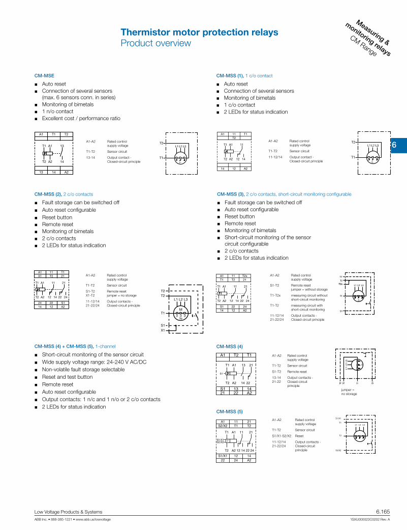
6
Measuring &
monitoring relays
CM Range
Low Voltage Products & Systems 6.165ABB Inc. • 888-385-1221 • www.abb.us/lowvoltage 1SXU000023C0202 Rev. A
A1
A1
13
14
14 A2
A2
T1
13
T2
T1
T2
CM-MSE
Auto reset Connection of several sensors
(max. 6 sensors conn. in series) Monitoring of bimetals 1 n/o contact Excellent cost / performance ratio
A1-A2 Rated control supply voltage
T1-T2 Sensor circuit
13-14 Output contact - Closed-circuit principle
A1
A1
14
14
12
12
A2
A2
11
11
T1T2
T1
T2
CM-MSS (1), 1 c/o contact
Auto reset Connection of several sensors Monitoring of bimetals 1 c/o contact 2 LEDs for status indication
A1-A2 Rated control supply voltage
T1-T2 Sensor circuit
11-12/14 Output contact - Closed-circuit principle
X1
T2
S1
M
L1 L2 L3
3p
T2
T1ϑ ϑ ϑ
A1
A1
14
14
12
12
A224 22 S1
A2
11
11
2422
21
T1X1 T2 21
T1
T2
CM-MSS (2), 2 c/o contacts
Fault storage can be switched off Auto reset configurable Reset button Remote reset Monitoring of bimetals 2 c/o contacts 2 LEDs for status indication
A1-A2 Rated control supply voltage
T1-T2 Sensor circuit
S1-T2 Remote reset X1-T2 jumper = no storage
11-12/14 Output contacts - 21-22/24 Closed-circuit principle
A1-A2 Rated control supply voltage
S1-T2 Remote reset jumper = without storage
T1-T2x measuring circuit without short-circuit monitoring
T1-T2 measuring circuit with short-circuit monitoring
11-12/14 Output contacts - 21-22/24 Closed-circuit principle
A1
A1
14
14
12
12
A2S1 22 24
A2
11
11
2422
21
T2xT1 T2 21
T1
T2
CM-MSS (3), 2 c/o contacts, short-circuit monitoring configurable
Fault storage can be switched off Auto reset configurable Reset button Remote reset Monitoring of bimetals Short-circuit monitoring of the sensor
circuit configurable 2 c/o contacts 2 LEDs for status indication
A1 T2 T1
S1 13 1421 22 A2
T1 13A1 21
T2 A2 14 22
S1
T1 11A1 21
T2 12A2 14 22 24
S1/X1S2/X2
J
A1 11 21S2/X2 T1 T2
S1/X1 12 1422 24 A2
S1/X1
S2/X2
T2
T1L1 L2 L3
CM-MSS (5)
CM-MSS (4)CM-MSS (4) + CM-MSS (5), 1-channel
Short-circuit monitoring of the sensor circuit Wide supply voltage range: 24-240 V AC/DC Non-volatile fault storage selectable Reset and test button Remote reset Auto reset configurable Output contacts: 1 n/c and 1 n/o or 2 c/o contacts 2 LEDs for status indication
A1-A2 Rated control supply voltage
T1-T2 Sensor circuit
S1-T2 Remote reset
13-14 Output contacts - 21-22 Closed-circuit principle
jumper = no storage
A1-A2 Rated control supply voltage
T1-T2 Sensor circuit
S1/X1-S2/X2 Reset
11-12/14 Output contacts - 21-22/24 Closed-circuit principle
Thermistor motor protection relaysProduct overview

6
Measuring &
monitorin
g relays
CM Range
6.166 Low Voltage Products & Systems
1SXU000023C0202 Rev. A ABB Inc. • 888-385-1221 • www.abb.us/lowvoltage
CM-MSS (6), 2-channel, single evaluation
S1-T2 jumpered = no storage
A1-A2 Rated control supply voltage
11-12/14, Output contacts - 21-22/24 Closed-circuit principle
1T1-T2 Sensor circuit 2T1-T2
Short-circuit monitoring for the sensor circuits
Wide supply voltage range: 24-240 V AC/DC
2 separate sensor circuits for monitoring of two motors or one motor with 2 sensor circuits (prewarning and final switch off)
Reset button Auto reset configurable Output contacts: 2 x 1 c/o contact 3 LEDs for status indication
Short-circuit monitoring for the sensor circuits
Wide supply voltage range 24-240 V AC/DC
Non-volatile fault storage configurable Remote reset Auto reset configurable Reset and test button Output contacts:
1 n/c and 1 n/o contact 4 LEDs for status indication
1T1-T2 Sensor circuits 2T1-T2 3T1-T2
S1-T2 Remote reset jumpered = no storage
CM-MSS (7), 3 sensor circuits, accumulative evaluation
A1-A2 Rated control supply voltage
13-14 Output contacts - 21-22 Closed-circuit principle
Short-circuit monitoring of the sensor circuit
Wide supply voltage range: 24-240 V AC/DC
Non-volatile fault storage configurable Remote reset Auto reset configurable Reset and test button Output contacts:
1 n/c, 1 n/o contact 7 LEDs for status indication
A1-A2 Rated control supply voltage
13-14 Output contacts - 21-22 Closed-circuit principle
CM-MSN, 6 sensor circuits, accumulative evaluation
accumulative evaluation = if any input exeeds the threshold, the output relay will trip
Thermistor motor protection relaysProduct overview

6
Measuring &
monitoring relays
CM Range
Low Voltage Products & Systems 6.167ABB Inc. • 888-385-1221 • www.abb.us/lowvoltage 1SXU000023C0202 Rev. A
Description
The thermistor motor protection relays CM-MSE, CM-MSS and CM-MSN are used to control motors equipped with PTC temperature sensors. The PTC temperature sensors are incorpo-rated in the motor windings to measure the motor heating. This enables direct control and evaluation of various operating conditions. Depending on the products also ATEX approvals for use in hazardous areas are availabe.ABB also offers PTC temperature sensors C011 (according to DIN 44081) which are suitable for embedding in motor windings.
Ordering details
Rated control supply voltage = measuring voltage
Referencecode
Catalognumber
Weight(1 pce) kg (lb)
24 V AC
CM-MSE
1SVR550805R9300 0.11 (0.24)
110-130 V AC 1SVR550800R9300 0.11 (0.24)
220-240 V AC 1SVR550801R9300 0.11 (0.24)
24 V AC/DC 1)
CM-MSS (1)1SVR430800R9100 0.15 (0.33)
220-240 V AC 1SVR430801R1100 0.15 (0.33)
24 V AC/DC 1)
CM-MSS (2)
1SVR430810R9300 0.15 (0.33)
24 V AC 1SVR430811R9300 0.15 (0.33)
110-130 V AC 1SVR430811R0300 0.15 (0.33)
220-240 V AC 1SVR430811R1300 0.15 (0.33)
24 V AC/DC 1
CM-MSS (3)
1SVR430710R9300 0.15 (0.33)
110-130 V AC 1SVR430711R0300 0.15 (0.33)
220-240 V AC 1SVR430711R1300 0.15 (0.33)
380-440 V AC 1SVR430711R2300 0.15 (0.33)
24-240 V AC/DC
CM-MSS (4) 2) 1SVR430720R0400 0.15 (0.33)
CM-MSS (5) 3) 1SVR430720R0300 0.15 (0.33)
CM-MSS (6) 1SVR430710R0200 0.15 (0.33)
CM-MSS (7) 1SVR430720R0500 0.15 (0.33)
CM-MSN 1SVR450025R0100 0.23 (0.51)
CM-MSE
CM-MSS (5)
CM-MSN
1) Not electrically isolated2) CM-MSS (4): 1-channel 1 n/c, 1 n/o3) CM-MSS (5): 1-channel 2 c/o
Thermistor motor protection relaysOrdering details

6
Measuring &
monitorin
g relays
CM Range
6.168 Low Voltage Products & Systems
1SXU000023C0202 Rev. A ABB Inc. • 888-385-1221 • www.abb.us/lowvoltage
Temperature sensor characteristics
-20
°C
101
102
103
104
TNF -
20
KTN
F - 5
K T NF
TNF +
5 K
TNF +
15
K
RPTC
[]
TPTC [°C]Ordering details
Rated response temperature TNF Color CodingReference
codeCatalognumber
Weight(1 pce) kg (lb)
70 °C white-brown C011-701) GHC0110003R0001 0.02 (0.044)
80 °C white-white C011-801) GHC0110003R0002 0.02 (0.044)
90 °C green-green C011-901) GHC0110003R0003 0.02 (0.044)
100 °C red-red C011-1001) GHC0110003R0004 0.02 (0.044)
110 °C brown-brown C011-1101) GHC0110003R0005 0.02 (0.044)
120 °C gray-gray C011-1201) GHC0110003R0006 0.02 (0.044)
130 °C blue-blue C011-1301) GHC0110003R0007 0.02 (0.044)
140 °C white-blue C011-1401) GHC0110003R0011 0.02 (0.044)
150 °C black-black C011-1501) GHC0110003R0008 0.02 (0.044)
160 °C blue-red C011-1601) GHC0110003R0009 0.02 (0.044)
170 °C white-green C011-1701) GHC0110003R0010 0.02 (0.044)
150 °C black-black C011-3-1502) GHC0110033R0008 0.05 (0.11)
1)Temperature sensor C011, standard version acc. to DIN 44081
2)Triple temperature sensor C011-3
Description
The PTC temperature sensors (temperature-dependent with positive temperature coefficient) are selected by the manufacturer of the motor depending on:
the motor insulation class according to IEC/EN 60034-11, the special characteristics of the motor, such as the conductor cross-section of the windings, the permissible
overload factor etc. special conditions prescribed by the user, such as the permissible ambient temperature, risks resulting from
locked rotor, extent of permitted overload etc.
One temperature sensor must be embedded in each phase winding. For instance, in case of three-phase squirrel cage motors, three sensors are embedded in the stator windings. For pole-changing motors with one wind-ing (Dahlander connection), 3 sensors are also sufficient. Pole-changing motors with two windings, however, require The sensors are suitable for embedding in motor windings with rated operating voltages of up to 600 V AC. Conductor length: 500 mm per sensor. A 14 V varistor can be connected in parallel to protect the sensors from overvoltage. Due to their characteristics, the thermistor motor protection relays can also be used with PTC temperature sensors of other manufacturers which comply with DIN 44 081 and DIN 44 082 6 sensors.
If an additional warning is required before the motor is switched off, separate sensors for a correspon dingly lower temperature must be embedded in the winding. They have to be connected to a second control unit.
Thermistor motor protection relaysOrdering detailsPTC temperature sensors C011

6
Measuring &
monitoring relays
CM Range
Low Voltage Products & Systems 6.169ABB Inc. • 888-385-1221 • www.abb.us/lowvoltage 1SXU000023C0202 Rev. A
Characteristic data Sensor type C011
Cold-state resistance 50 -100 q at 25 °CWarm-state resistance ± 5 up to 6 K of rated response temperature TNF 10 000 qThermal time constant, sensor open 1) < 5 sPermitted ambient temperature +180 °C
Technical data
.
Rated response temperature w tolerance TNF w iTNF
PTC resistance R from -20 °C to TNF - 20 K
PTC resistance R at PTC temperatures of:
TNF - iTNF (UPTC m 2.5 V)
TNF + iTNF (UPTC m 2.5 V)
TNF + 15 K (UPTC m 7.5 V)
70 w5 °C
m 100 q
m 570 q 570 q -80 w5 °C90 w5 °C
m 550 q 1330 q 4000 q
100 w5 °C110 w5 °C120 w5 °C130 w5 °C140 w5 °C150 w5 °C160 w5 °C170 w7 °C m 570 q 570 q -
1) Not embedded in windings. 2) For triple temperature sensor take values x 3.
Thermistor motor protection relaysTechnical informationPTC temperature sensors C011
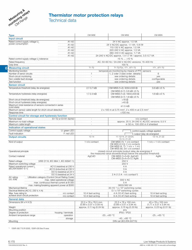
6
Measuring &
monitorin
g relays
CM Range
6.170 Low Voltage Products & Systems
1SXU000023C0202 Rev. A ABB Inc. • 888-385-1221 • www.abb.us/lowvoltage
Type CM-MSE CM-MSS CM-MSN
Input circuitRated control supply voltage Uspower consumption
A1-A2 24 V AC approx. 1.5 VAA1-A2 24 V AC/DC approx. 1.1 VA / 0.6 WA1-A2 110-130 V AC approx. 1.5 VAA1-A2 220-240 V AC approx. 1.5 VAA1-A2 380-440 V AC approx. 1.7 VAA1-A2 24-240 V AC/DC approx. 1.4-1.7 W / approx. 3.5-5.7 VA
Rated control supply voltage Us tolerance -15 % ... +10 %Rated frequency AC: 50-60 Hz / 24-240 V AC/DC versions: 15-400 HzDuty time 100 %Measuring circuit T1-T2 T1-T2/T2x, 1T1...6T1-T2 1T1...6T1-T2
Monitoring function temperature monitoring by means of PTC sensorsNumber of senor circuits 1 1, 2 oder 3 (see order. details) 6Short-circuit monitoring - see ordering details yesNon-volatile fault storage - see ordering details configurableTest function - see ordering details yesSensor circuitTemperature threshold (relay de-energizes) 2.7-3.7 kq CM-MSS (1+2): 3050w550 q
CM-MSS (3-7): 3.6 kq w5 %3.6 kq w5 %
Temperature hysteresis (relay energizes) 1.7-2.3 kq CM-MSS (1+2): 1900w400 q CM-MSS (3-7): 1.6 kq w5 %
1.6 kq w5 %
Short-circuit threshold (relay de-energizes) <18 qShort-circuit hysteresis (relay energizes) >45 qMaximum total resistance of sensors connected in series (cold state) m1.5 kq
Maximum sensor cable length for short-circuit detection 2 x 100 m at 0.75 mm2, 2 x 400 m at 2.5 mm2
Response time <100 msControl circuit for storage and hysteresis functionRemote reset S1-T2 or S1/X1-S2/X2 - n/o contactMaximum no-load voltage - approx. 25 V, 24-240 V; AC/DC versions: 5.5 VMaximum cable length - m 50 m, 100-200 m if shieldedIndication of operational statesControl supply voltage U: green LED - V: control supply voltage appliedFault indication F: red LED - V: output relay de-energizedOutput circuits 13-14 11-12/14, 21-22/24,
13-14, 21-2213-14, 21-22
Kind of output 1 n/o contact CM-MSS (1): 1 c/o contact CM-MSS (2,3,5): 2 c/o contacts CM-MSS (4, 7): 1 n/o + 1 n/c CM-MSS (6): 2x1 c/o contact
1 n/o + 1 n/c contact
Operational principle closed-circuit principle (output relay de-energizes if the measured value exceeds/drops below the adjusted threshold)
Contact material AgCdO CM-MSS (1+2+6): AgCdO CM-MSS (3+4+5+7): AgNi
AgNi
Rated voltage (VDE 0110, IEC 664-1, IEC 60947-1) 250 VMaximum switching voltage 250 VRated operational current Ie (IEC/EN 60947-5-1)
AC12 (resistive) at 230 V 4 AAC15 (inductive) at 230 V 3 A
DC12 (resistive) at 24 V 4 ADC13 (resistive) at 24 V 2 A (1.5 A - n/c contact1))
AC rating(UL 508)
Utilization category (Control Circuit Rating Code)max. rated operational voltage 300 V AC
max. continuous thermal current at B 300 5 Amax. making/breaking apparent power at B300 3600/360 VA
Mechanical lifetime 30 (10 1) ) x 106 switching cyclesElectrical lifetime (AC12, 230 V, 4 A) 0.1 x 10⁶ switching cyclesMax. fuse rating toachieve short-circuit protection
n/c contact 10 A fast-acting 4 A (10 A1)) fast-acting 10 A fast-actingn/o contact 10 A fast-acting 6 A (10 A1)) fast-acting 10 A fast-acting
General dataDimensions (W x H X D) 22.5 x 78 x 78.5 mm
(0.89 x 3.07 x 3.09 in)22.5 x 78 x 100 mm
(0.89 x 3.07 x 3.94 in)45 x 78 x 100 mm
(1.77 x 3.07 x 3.94 in)Weight approx. 0.11 kg (0.24 lb) approx. 0.15 kg (0.33 lb) approx. 0.23 kg (0.51 lb)Mounting position anyDegree of protection housing / terminals IP50 / IP20Ambient temperature range
operation -20...+60 °C -25...+65 °C storage -40...+85 °C
Mounting DIN rail (IEC/EN 60715)
1) 1SVR 430 710 R 0200, 1SVR 430 8xx R xxxx
Thermistor motor protection relaysTechnical data

6
Measuring &
monitoring relays
CM Range
Low Voltage Products & Systems 6.171ABB Inc. • 888-385-1221 • www.abb.us/lowvoltage 1SXU000023C0202 Rev. A
Type CM-MSE CM-MSS CM-MSN
Electrical connectionWire size fine strand with wire end ferrule 2 x 1.5 mm2
(2 x 16 AWG)2 x 2.5 mm2 (2 x 14 AWG)
fine strand without wire end ferrule
2 x 0.75-1.5 mm2 (2 x 18-16 AWG)
2 x 0.75-2.5 mm2 (2 x 18-14 AWG)
rigid 2 x 1-1.5 mm2 (2 x 18-16 AWG)
2 x 0.75-2.5 mm2 (2 x 18-14 AWG)
Stripping length 2 x 0.75-1.5 mm2 (2 x 18-16 AWG)
2 x 0.5-4 mm2 (2 x 20-12 AWG)
Tightening torque 10 mm (0.39 inch) 7 mm (0.28 inch)StandardsProduct standard IEC 255-6, EN 60255-6Low Voltage Directive 2006/95/ECEMC Directive 2004/108/EC, 91/263/EEC, 92/31/EEC, 93/68/EEC, 93/67/EECElectromagnetic compatibility EN 61000-6-2, EN 61000-6-4
electrostatic discharge IEC/EN 61000-4-2 Level 3 (6 kV / 8 kV)radiated, radio-frequency, electromagnetic field
IEC/EN 61000-4-3 Level 3 (10 V/m)
electrical fast transient /burst IEC/EN 61000-4-4 Level 3 (2 kV / 5 kHz)surge IEC/EN 61000-4-5 Level 3/4 (1/2 kV)conducted disturbances, induced by radio-frequency fields
IEC/EN 61000-4-6 Level 3 (10 V)
Operational reliability (IEC 68-2-6) 6 g 4 g 5 gResistance to vibration (IEC 68-2-6) 10 g 6 g 10 gEnvironmental testing (IEC 68-2-30 ) 24 h cycle time, 55 °C, 93 % rel., 96 hIsolation dataRated voltage between supply, measuring and output circuit 250 VRated impulse withstand voltage between all isolated circuits 4 kV / 1.2 - 50 µsTest voltage between all isolated circuits 2.5 kV, 50 Hz, 1 min.Pollution degree 3Overvoltage category III
Thermistor motor protection relaysTechnical data

6
Measuring &
monitorin
g relays
CM Range
6.172 Low Voltage Products & Systems
1SXU000023C0202 Rev. A ABB Inc. • 888-385-1221 • www.abb.us/lowvoltage
Notes
6
Measuring &
monitoring relays
CM Range
Low Voltage Products & Systems 6.173ABB Inc. • 888-385-1221 • www.abb.us/lowvoltage 1SXU000023C0202 Rev. A
Temperature monitoring relays
Tem
pera
ture
mon
itorin
g re
lays
CM
-E R
ange
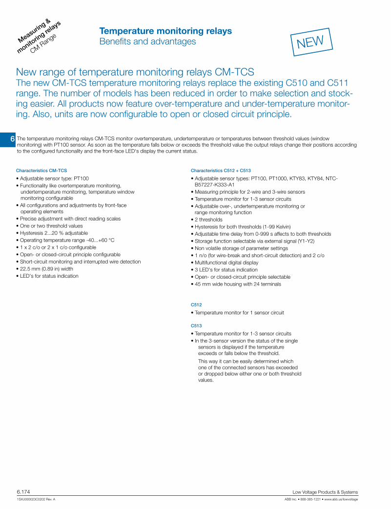
6
Measuring &
monitorin
g relays
CM Range
6.174 Low Voltage Products & Systems
1SXU000023C0202 Rev. A ABB Inc. • 888-385-1221 • www.abb.us/lowvoltage
NEW
New range of temperature monitoring relays CM-TCSThe new CM-TCS temperature monitoring relays replace the existing C510 and C511 range. The number of models has been reduced in order to make selection and stock-ing easier. All products now feature over-temperature and under-temperature monitor-ing. Also, units are now configurable to open or closed circuit principle.
Characteristics CM-TCS
• Adjustable sensor type: PT100• Functionality like overtemperature monitoring,
undertemperature monitoring, temperature window monitoring configurable
• All configurations and adjustments by front-face operating elements
• Precise adjustment with direct reading scales• One or two threshold values• Hysteresis 2...20 % adjustable• Operating temperature range -40...+60 °C• 1 x 2 c/o or 2 x 1 c/o configurable• Open- or closed-circuit principle configurable• Short-circuit monitoring and interrupted wire detection• 22.5 mm (0.89 in) width• LED's for status indication
Characteristics C512 + C513
• Adjustable sensor types: PT100, PT1000, KTY83, KTY84, NTC-B57227-K333-A1
• Measuring principle for 2-wire and 3-wire sensors• Temperature monitor for 1-3 sensor circuits• Adjustable over-, undertemperature monitoring or
range monitoring function• 2 thresholds• Hysteresis for both thresholds (1-99 Kelvin)• Adjustable time delay from 0-999 s affects to both thresholds• Storage function selectable via external signal (Y1-Y2)• Non volatile storage of parameter settings• 1 n/o (for wire-break and short-circuit detection) and 2 c/o• Multifunctional digital display• 3 LED's for status indication• Open- or closed-circuit principle selectable• 45 mm wide housing with 24 terminals
The temperature monitoring relays CM-TCS monitor overtemperature, undertemperature or temperatures between threshold values (window monitoring) with PT100 sensor. As soon as the temperature falls below or exceeds the threshold value the output relays change their positions according to the configured functionality and the front-face LED‘s display the current status.
C513
• Temperature monitor for 1-3 sensor circuits• In the 3-sensor version the status of the single
sensors is displayed if the temperature exceeds or falls below the threshold.
This way it can be easily determined which one of the connected sensors has exceeded or dropped below either one or both threshold values.
C512
• Temperature monitor for 1 sensor circuit
Temperature monitoring relaysBenefits and advantages

6
Measuring &
monitoring relays
CM Range
Low Voltage Products & Systems 6.175ABB Inc. • 888-385-1221 • www.abb.us/lowvoltage 1SXU000023C0202 Rev. A
NEW
Cat
alo
g n
um
ber
1SV
R63
0740
R91
00
1SV
R63
0740
R01
00
1SV
R63
0740
R92
00
1SV
R63
0740
R02
00
1SV
R63
0740
R93
00
1SV
R63
0740
R03
00
1SA
R70
0016
R00
05
1SA
R70
0016
R00
10
1SA
R70
0016
R00
10
Ref
eren
ceco
de
CM
-TC
S.2
1
CM
-TC
S.1
1
CM
-TC
S.2
2
CM
-TC
S.1
2
CM
-TC
S.2
3
CM
-TC
S.1
3
C51
2-24
C51
2-W
C51
3-W
Rated control supply voltage Us
24 V AC/DC 24-240 V AC/DC Technology
analogue digital Sensor circuits (2 or 3 wire)
no of temperature sensors 1 1 1 1 1 1 1 1 3
no of thresholds 2 2 2 2 2 2 2 2 3
Sensor type
PT100 PT100, KTY83, KTY84, NTC Measuring temperature range
-50...+50 °C 0...+100 °C 0...+200 °C -50...+500 °C Monitoring function
overtemperature undertemperature window temperature Operating principleopen or closed principle Output contactsn/o 1 1 1
c/o 2 2 2 2 2 2 2 2 2
Conversion1SAR700001R0005 C510.01-24 24 V AC/DC no device with pure 230 V AC supply.
1SAR700001R0006 C510.01-K 110/230 V AC 1SAR700002R0005 C510.02-24 24 V AC/DC no device with pure 230 V AC supply.
1SAR700002R0006 C510.02-K 110/230 V AC 1SAR700003R0005 C510.03-24 24 V AC/DC no device with pure 230 V AC supply.
1SAR700003R0006 C510.03-K 110/230 V AC 1SAR700004R0005 C510.11-24 24 V AC/DC no device with pure 230 V AC supply.
1SAR700004R0006 C510.11-K 110/230 V AC 1SAR700005R0005 C510.12-24 24 V AC/DC no device with pure 230 V AC supply.
1SAR700005R0006 C510.12-K 110/230 V AC 1SAR700006R0005 C510.13-24 24 V AC/DC no device with pure 230 V AC supply.
1SAR700006R0006 C510.13-K 110/230 V AC 1SAR700011R0005 C511.01-24 24 V AC/DC 1SAR700011R0006 C511.01-W 24-240 V AC/DC 1SAR700012R0005 C511.02-24 24 V AC/DC 1SAR700012R0006 C511.02-W 24-240 V AC/DC 1SAR700013R0005 C511.03-24 24 V AC/DC 1SAR700013R0010 C511.03-W 24-240 V AC/DC 1SAR700016R0005 C511.11-24 24 V AC/DC 1SAR700016R0010 C511.11-W 24-240 V AC/DC 1SAR700016R0005 C511.12-24 24 V AC/DC 1SAR700016R0010 C511.12-W 24-240 V AC/DC 1SAR700016R0005 C511.13-24 24 V AC/DC 1SAR700016R0010 C511.13-W 24-240 V AC/DC
Temperature monitoring relaysSelection and conversion

6
Measuring &
monitorin
g relays
CM Range
6.176 Low Voltage Products & Systems
1SXU000023C0202 Rev. A ABB Inc. • 888-385-1221 • www.abb.us/lowvoltage
NEWDescription
Acquisition, messaging and regulation of temperatures of solid, liquid and gaseous media in processes and machines via PT100, PT1000, KTY83, KTY84 or NTC sensors.ABB offers different temperature monitoring relays to meet the needs of your application:
Ordering details - Temperature monitoring relays
Rated control supply voltage
Measuringrange
Referencecode
Catalognumber
Weight(1 pce)
kg (lb)
24-240 V AC/DC
-50...+50 °C CM-TCS.111) 1SVR630740R0100 0.127 (0.281)
0...+100 °C CM-TCS.121) 1SVR630740R0200 0.127 (0.281)
0...+200 °C CM-TCS.131) 1SVR630740R0300 0.127 (0.281)
24 V AC/DC
-50...+50 °C CM-TCS.211) 1SVR630740R9100 0.141 (0.310)
0...+100 °C CM-TCS.221) 1SVR630740R9200 0.141 (0.310)
0...+200 °C CM-TCS.231) 1SVR630740R9300 0.141 (0.310)
24 V AC/DC
-50...+500 °C *)
C512-242) 1SAR700100R0005 0.32 (0.71)
24-240 V AC/DC C512-W2) 1SAR700100R0010 0.33 (0.73)
24-240 V AC/DC C513-W2) 1SAR700110R0010 0.34 (0.75)
Ordering details - Replaceable cover marking for digital devices
Use for LanguageReference
codeCatalognumber
Weight(1 pce) kg (lb)
C512 German C512-D 1SVR700101R0100
C512 English C512-E 1SVR700102R0100
C513 German C513-D 1SVR700111R0100
C513 English C513-E 1SVR700112R0100
CM-TCS
C512, C513
*) The measuring range depends on the used sensor type:
PT100: -50...+500 °C KTY83: -50...+175 °C PT1000: -50...+500 °C KTY84: -40...+300 °C NTC: +80...+160 °C
(Typ Siemens Matsushita B57272-A333-A1 - 100 °C: 1,8 kq, 25 °C: 32,762 kq)
1) PT100 sensors, 2 or 3 wire connection, 2 thresholds adjustable2) PT100, PT1000, KTY83, KTY84, NTC-B57227-K333-A1, 2 or 3 wire connection, 2 thresholds, multifunctional display.
Open or closed circuit principle adjustable, 1 n/o, 2 c/o contacts
(Typ Siemens Matsushita B57272-A333-A1 - 100 °C: 1.8 kW, 25 °C: 32.762 kW)
Temperature monitoring relaysOrdering details
Ordering details - New range temperature monitoring relays
Rated controlsupply voltage
Measuringrange
Referencecode
Catalognumber
Weight(1 pce) kg (lb)
24-240 V AC/DC
-50...+50 °CCM-TCS.11S 1SVR730740R0100 0.151 (0.333)
CM-TCS.11P 1SVR740740R0100 0.140 (0.309)
0...+100 °CCM-TCS.12S 1SVR730740R0200 0.151 (0.333)
CM-TCS.12P 1SVR740740R0200 0.140 (0.309)
0...+200 °CCM-TCS.13S 1SVR730740R0300 0.151 (0.333)
CM-TCS.13P 1SVR740740R0300 0.140 (0.309)
24 V AC/DC
-50...+50 °CCM-TCS.21S 1SVR730740R9100 0.138 (0.304)
CM-TCS.21P 1SVR740740R9100 0.127 (0.280)
0...+100 °CCM-TCS.22S 1SVR730740R9200 0.138 (0.304)
CM-TCS.22P 1SVR740740R9200 0.127 (0.280)
0...+200 °CCM-TCS.23S 1SVR730740R9300 0.138 (0.304)
CM-TCS.23P 1SVR740740R9300 0.127 (0.280)

6
Measuring &
monitoring relays
CM Range
Low Voltage Products & Systems 6.177ABB Inc. • 888-385-1221 • www.abb.us/lowvoltage 1SXU000023C0202 Rev. A
NEW
Functional descriptionCM-TCS
The temperature monitoring relays CM-TCS monitor overtemperature, undertemperature, or temperatures between two threshold values (window monitoring) with PT100 sensor. As soon as the temperature falls below or exceeds the threshold value the output relays change their positions according to the configured functionality and the front-face LEDs display the current status. Regardless of the selected configuration, the device is monitoring its measuring circuit for interrupted wires or short-circuits.
Function diagramsCM-TCS - Overvoltage
OverviewThe temperature monitoring relays can be used for temperature measure-ment in solid, liquid and gaseous media. The temperature is acquired by the sensor in the medium, evaluated by the device and monitored to de-termine whether it is within an operating range (range monitoring function) or has exceeded or fallen below a threshold.
DIP switches
Position 4 1 2 3
ON
OFF
i g r pqshj
ON OFF (default)
DIP switch 1Monitoring principle
Overtemperature monitoring pIf overtemperature monitoring is selected, the CM-TCS recognizes temperatures above the selected threshold and trips the output relay according to the selected operating principle.
Undertemperature monitoring qIf undertemperature monitoring is selected, the CM-TCS recognizes temperatures below the selected threshold and trips the output relay according to the selected operating principle.
DIP switch 2Temperature windowmonitoring
Temperature window monitoring activated rIf temperature window monitoring is selected, the CM-TCS monitors over- and undertemperature. If temperature window monitoring is acti-vated, DIP switch 1 is disabled.
Temperature window monitoring de-activated sTemperature window monitoring is de-selected.
DIP switch 3Operating principleof the output relays
Closed-circuit principle gIf closed-circuit principle is selected, the output relays are energized. They de-energize if a fault is occurring.
Open-circuit principle hIf open-circuit principle is selected, the output relays are deenergized. They energize if a fault is occurring.
DIP switch 42 x 1 c/o contact,1 x 2 c/o contacts
2 x 1 c/o (SPDT) contact iIf operating principle 2 x 1 c/o contact is selected, the output relay R1 (11-12/14) reacts to threshold value t1 and the output relay R2 (21-22/24) reacts to threshold value t2.
1 x 2 c/o (SPDT) contacts jIf operating principle 1 x 2 c/o contacts is selected, both output relays R1 (11-12/14) and R2 (21-22/24) react synchronously to one threshold value.Overtemperature monitoring: Settings of the threshold value t2 have no effect on the operation.Undertemperature monitoring: Settings of the threshold values t2 have no effect on the operation.
A1-A2
11-1411-12
21-2421-22
11-1411-12
21-2421-22
closed
open
Threshold ϑ1
Hysteresis
Measured value
U: green LED
ϑ: red LED
R: yellow LED
U: green LED
ϑ: red LED
R: yellow LED
Open-circuit principle
Closed-circuit principle
A1-A2
11-1411-12
21-2421-22
11-1411-12
21-2421-22
closed
open
Hysteresis
Measured value
U: green LED
ϑ: red LED
R: yellow LED
U: green LED
ϑ: red LED
R: yellow LED
Open-circuit principle
Closed-circuit principle
Threshold ϑ2
A1-A2
11-1411-12
21-2421-22
11-1411-12
21-2421-22
closed
open
Threshold ϑ1
Hysteresis
Measured value
Threshold ϑ2
Hysteresis
Open-circuit principle
U: green LED
ϑ: red LED
R: yellow LED
Closed-circuit principle
U: green LED
ϑ: red LED
R: yellow LED
CM-TCS - Undervoltage
CM-TCS - Temperature monitoring
Temperature monitoring relaysOverview, functional description and diagrams

6
Measuring &
monitorin
g relays
CM Range
6.178 Low Voltage Products & Systems
1SXU000023C0202 Rev. A ABB Inc. • 888-385-1221 • www.abb.us/lowvoltage
NEW
Characteristic curves of resistance sensors
-100 0 100 200 300 400 500
5000
4000
3000
2000
1000
0
NTC
KTY83 KTY84 PT1000
PT100
Res
ista
nce
in q
Temperature in °C
t
t
t
Us
K1
K2
1J
2J
t
t t
Us
K1
K2
1J
2J
t
t
t
Us
K2
K1
1J
2J
t
t
t
Us
K1
K2
1J
2J
tt
t
Us
K1
K2
1J
2J
t
t
Us
-Y1 Y2
K1
tK2
1J
2J
t
t t
Us
K2
K1
1ϑ
2ϑ
Function principle with storage function - C512/C513
using overtemperature with closed-circuit principle as an example
Range monitoring - C512/C513
absolute limit
hysteresis
Overtemperature - C512/C513
Open-circuit principle
Open-circuit principle Closed-circuit principle
Undertemperature - C512/C513
Open-circuit principle Closed-circuit principle
Functional descriptionDigital tripping devices
Once the temperature has reached the set threshold of υ1, output relay K1 changes its switching state after the set time delay t has elapsed (K2 reacts in the same way for υ2).
Function diagrams
Temperature monitoring relaysOverview, functional description and diagrams
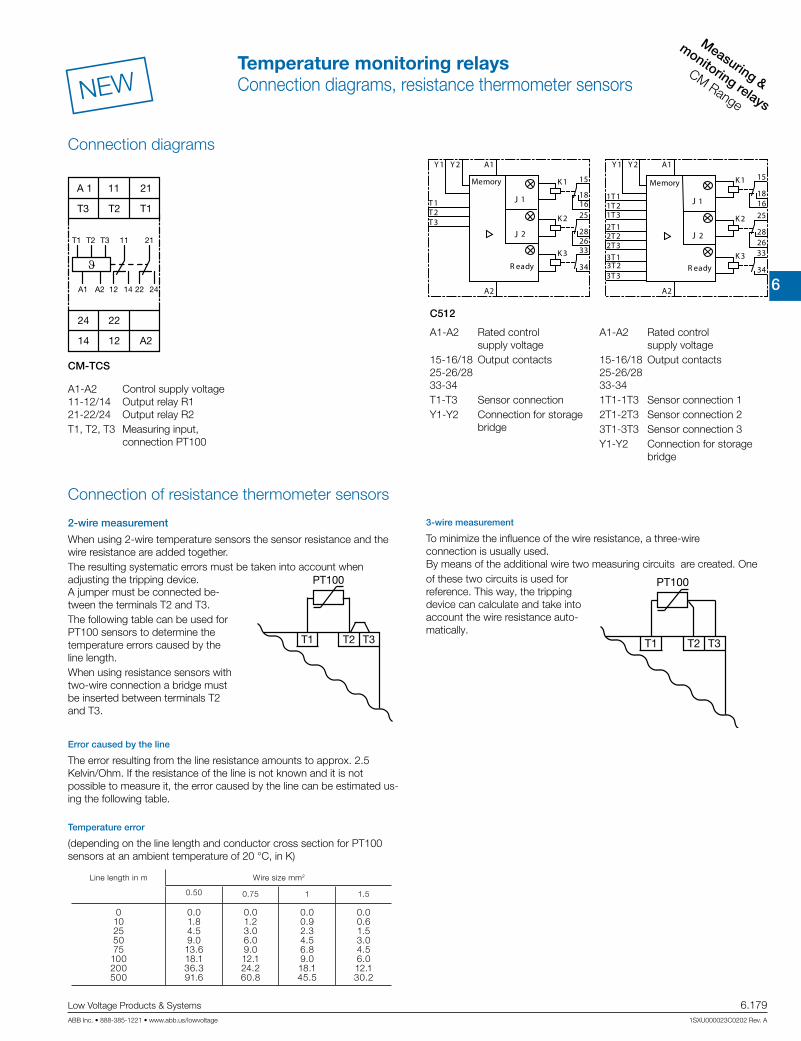
6
Measuring &
monitoring relays
CM Range
Low Voltage Products & Systems 6.179ABB Inc. • 888-385-1221 • www.abb.us/lowvoltage 1SXU000023C0202 Rev. A
NEW
A2
A1
K1 15
1618
K2 25
28
K3 33
34
26
Y2Y1
1T11T21T32T12T22T33T13T23T3
Memory
R eady
J 1
J 2
A2
A1
T1
K1 15
16T2T3
18
K2 25
28
K3 33
34
26
Y2Y1
Memory
R eady
J 1
J 2
CM-TCS
C512
Connection diagrams
Connection of resistance thermometer sensors
A1-A2 Control supply voltage 11-12/14 Output relay R1 21-22/24 Output relay R2T1, T2, T3 Measuring input, connection PT100
A1-A2 Rated control supply voltage15-16/18 Output contacts 25-26/28 33-34T1-T3 Sensor connectionY1-Y2 Connection for storage bridge
A1-A2 Rated control supply voltage15-16/18 Output contacts 25-26/28 33-341T1-1T3 Sensor connection 12T1-2T3 Sensor connection 23T1-3T3 Sensor connection 3Y1-Y2 Connection for storage bridge
A 1 11 21
T3
24
T2 T1
22
14 12 A2
T1 T2 T3 11 21
A1 A2 12 14 22 24
T2
PT100
T3T1 T2
PT100
T3T1
Temperature error
(depending on the line length and conductor cross section for PT100 sensors at an ambient temperature of 20 °C, in K)
2-wire measurement
When using 2-wire temperature sensors the sensor resistance and the wire resistance are added together.The resulting systematic errors must be taken into account when adjusting the tripping device.
Error caused by the line
The error resulting from the line resistance amounts to approx. 2.5 Kelvin/Ohm. If the resistance of the line is not known and it is not possible to measure it, the error caused by the line can be estimated us-ing the following table.
3-wire measurement
To minimize the influence of the wire resistance, a three-wire connection is usually used. By means of the additional wire two measuring circuits are created. One
A jumper must be connected be-tween the terminals T2 and T3.The following table can be used for PT100 sensors to determine the temperature errors caused by the line length.When using resistance sensors with two-wire connection a bridge must be inserted between terminals T2 and T3.
of these two circuits is used for reference. This way, the tripping device can calculate and take into account the wire resistance auto-matically.
Line length in m Wire size mm2
0.50 0.75 1 1.5
010255075
100200500
0.01.84.59.013.618.136.391.6
0.01.23.06.09.012.124.260.8
0.00.92.34.56.89.018.145.5
0.00.61.53.04.56.012.130.2
Temperature monitoring relaysConnection diagrams, resistance thermometer sensors

6
Measuring &
monitorin
g relays
CM Range
6.180 Low Voltage Products & Systems
1SXU000023C0202 Rev. A ABB Inc. • 888-385-1221 • www.abb.us/lowvoltage
NEW
Type CM-TCS.11/12/13 CM-TCS.21/22/23
Input circuit
Rated control supply voltage UsA1-A2 24-240 V AC/DC 24 V AC/DC
Rated control supply voltage Us tolerance -15...+10 %Typical current / power / consumption
24 V DC 33 mA / 0.8 VA 18 mA / 0.45 VA115 V AC 12.5 mA / 1.5 VA n/a230 V AC 13 mA / 2.9 VA n/a
Rated frequency AC 13.5-440 Hz 50/60 HzFrequency range AC 13.5-440 Hz 45-65 HzPower failure buffering time min. 20 msMeasuring circuit T1, T2, T3
Sensor type PT100Connection of the sensor 2-wire yes, jumper between T2-T3
3-wire yes, use terminal T1, T2, T3Monitoring function overtemperature, undertemperature or window monitoringThreshold values adjustable within themeasuring range
CM-TCS.x1 -50…+50 °CCM-TCS.x2 0…+100 °CCM-TCS.x3 0…+200 °C
Number of possible thresholds 2Tolerance of the adjusted threshold value typ. ±5 % of the range end valueHysteresis related to the threshold value 2-20 % of threshold value, min. 1 °CMeasuring principle continuous currentTypical current in the sensor circuit 0.8 mAInterrupted wire detection yes, indicated via LED statusShort-circuit detection yes, indicated via LED statusAccuracy within the rated control supply voltage tolerance < 0.2 °C / or < 0.01 %/KAccuracy within the temperature range < 0.2 °C / or < 0.01 %/KRepeat accuracy (constant parameters) < 0.2 % of full scaleMaximum measuring cycle 320 msOutput circuitKind of output 2 x 1 or 1 x 2 c/o (SPDT) contacts configurableOperating principle1) open- or closed-circuit principle configurableContact material AgNi alloy, Cd freeRated voltage (VDE 0110, IEC 60947-1) 250 V AC / 300 V DCMinimum switching voltage / Minimum switching current 24 V / 10 mAMaximum switching voltage / Maximum switching current see ‘Load limit curves'Rated operating current Ie (IEC/EN 60947-1-5) AC12 (resistive) 230 V 4 A
AC15 (inductive 230 V 3 ADC12 (resistive) 24 V 4 A
DC13 (inductive) 24 V 2 AAC Rating (UL508) utilization category B 300, pilot duty general purpose (250 V, 4 A, cos ϕ 0.75)
maximum rated operational voltage 250 V ACmaximum continuous thermal current at B 300 4 A
maximum making/breaking apparent power at B 300 3600/360 VAMechanical lifetime 30 x 106 switching cyclesElectrical lifetime ((AC12, 230 V, 4 A) 0.1 x 10⁶ switching cyclesMaximum fuse rating to achieve short-circuit protection n/c contact 6 A fast-acting
n/o contact 10 A fast-actingConventional thermal current Ith acc. IEC/EN 60947-1 4 A
General dataDimensions (W x H x D) 22.5 x 78 x 100 mm (0.89 x 3.07 x 3.94 in)Mounting position anyWeight net weight 0.141 kg (0. 310 lb) 0.127 kg (0. 281 lb)
gross weight 0.166 kg (0.336 lb) 0.153 kg (0.367 lb)Degree of protection enclosure / terminals IP50 / IP20Ambient temperature range operation -40...+60 °C
storage/transport -40...+85 °CMounting DIN rail (IEC/EN 60715), snap-on mounting without any tool
Temperature monitoring relaysTechnical data
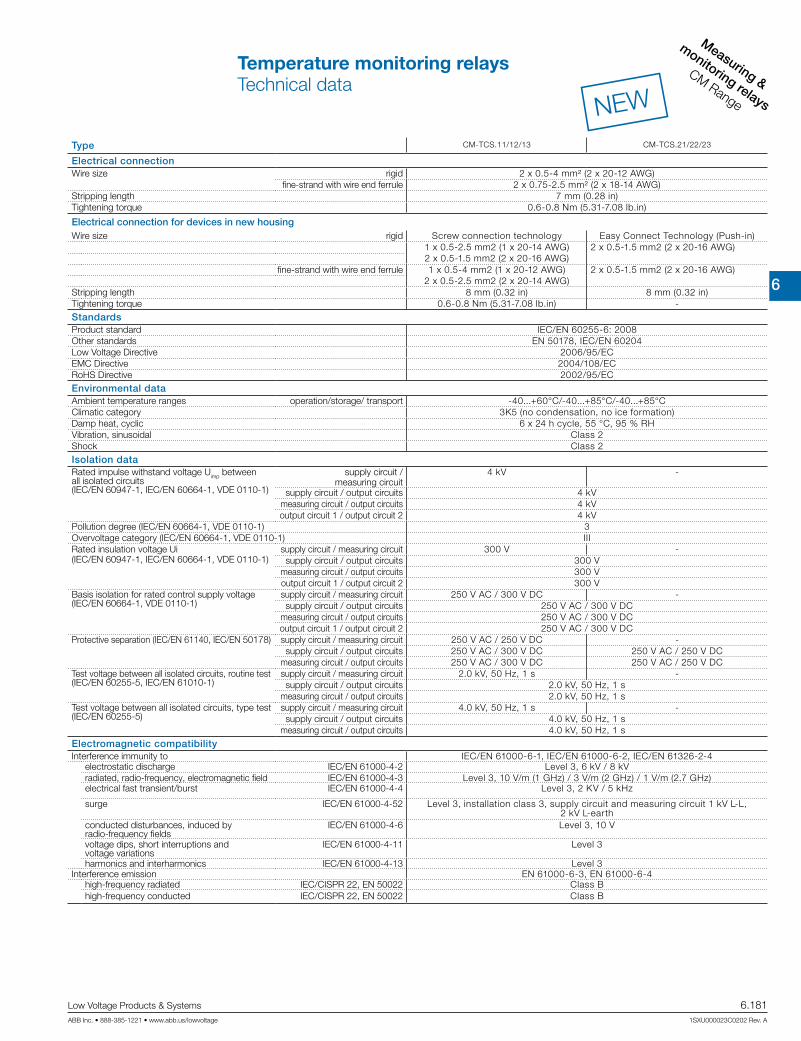
6
Measuring &
monitoring relays
CM Range
Low Voltage Products & Systems 6.181ABB Inc. • 888-385-1221 • www.abb.us/lowvoltage 1SXU000023C0202 Rev. A
NEW
Type CM-TCS.11/12/13 CM-TCS.21/22/23
Electrical connectionWire size rigid 2 x 0.5-4 mm² (2 x 20-12 AWG)
fine-strand with wire end ferrule 2 x 0.75-2.5 mm² (2 x 18-14 AWG)Stripping length 7 mm (0.28 in)Tightening torque 0.6-0.8 Nm (5.31-7.08 lb.in)
Electrical connection for devices in new housingWire size rigid Screw connection technology Easy Connect Technology (Push-in)
1 x 0.5-2.5 mm2 (1 x 20-14 AWG)2 x 0.5-1.5 mm2 (2 x 20-16 AWG)
2 x 0.5-1.5 mm2 (2 x 20-16 AWG)
fine-strand with wire end ferrule 1 x 0.5-4 mm2 (1 x 20-12 AWG)2 x 0.5-2.5 mm2 (2 x 20-14 AWG)
2 x 0.5-1.5 mm2 (2 x 20-16 AWG)
Stripping length 8 mm (0.32 in) 8 mm (0.32 in)Tightening torque 0.6-0.8 Nm (5.31-7.08 lb.in) -StandardsProduct standard IEC/EN 60255-6: 2008Other standards EN 50178, IEC/EN 60204Low Voltage Directive 2006/95/ECEMC Directive 2004/108/ECRoHS Directive 2002/95/ECEnvironmental dataAmbient temperature ranges operation/storage/ transport -40...+60°C/-40...+85°C/-40...+85°CClimatic category 3K5 (no condensation, no ice formation)Damp heat, cyclic 6 x 24 h cycle, 55 °C, 95 % RHVibration, sinusoidal Class 2Shock Class 2Isolation dataRated impulse withstand voltage Uimp betweenall isolated circuits (IEC/EN 60947-1, IEC/EN 60664-1, VDE 0110-1)
supply circuit / measuring circuit
4 kV -
supply circuit / output circuits 4 kVmeasuring circuit / output circuits 4 kVoutput circuit 1 / output circuit 2 4 kV
Pollution degree (IEC/EN 60664-1, VDE 0110-1) 3Overvoltage category (IEC/EN 60664-1, VDE 0110-1) IIIRated insulation voltage Ui(IEC/EN 60947-1, IEC/EN 60664-1, VDE 0110-1)
supply circuit / measuring circuit 300 V -supply circuit / output circuits 300 V
measuring circuit / output circuits 300 Voutput circuit 1 / output circuit 2 300 V
Basis isolation for rated control supply voltage(IEC/EN 60664-1, VDE 0110-1)
supply circuit / measuring circuit 250 V AC / 300 V DC -supply circuit / output circuits 250 V AC / 300 V DC
measuring circuit / output circuits 250 V AC / 300 V DCoutput circuit 1 / output circuit 2 250 V AC / 300 V DC
Protective separation (IEC/EN 61140, IEC/EN 50178) supply circuit / measuring circuit 250 V AC / 250 V DC -supply circuit / output circuits 250 V AC / 300 V DC 250 V AC / 250 V DC
measuring circuit / output circuits 250 V AC / 300 V DC 250 V AC / 250 V DCTest voltage between all isolated circuits, routine test(IEC/EN 60255-5, IEC/EN 61010-1)
supply circuit / measuring circuit 2.0 kV, 50 Hz, 1 s -supply circuit / output circuits 2.0 kV, 50 Hz, 1 s
measuring circuit / output circuits 2.0 kV, 50 Hz, 1 sTest voltage between all isolated circuits, type test(IEC/EN 60255-5)
supply circuit / measuring circuit 4.0 kV, 50 Hz, 1 s -supply circuit / output circuits 4.0 kV, 50 Hz, 1 s
measuring circuit / output circuits 4.0 kV, 50 Hz, 1 sElectromagnetic compatibilityInterference immunity to IEC/EN 61000-6-1, IEC/EN 61000-6-2, IEC/EN 61326-2-4
electrostatic discharge IEC/EN 61000-4-2 Level 3, 6 kV / 8 kVradiated, radio-frequency, electromagnetic field IEC/EN 61000-4-3 Level 3, 10 V/m (1 GHz) / 3 V/m (2 GHz) / 1 V/m (2.7 GHz)electrical fast transient/burst IEC/EN 61000-4-4 Level 3, 2 KV / 5 kHz
surge IEC/EN 61000-4-52 Level 3, installation class 3, supply circuit and measuring circuit 1 kV L-L, 2 kV L-earth
conducted disturbances, induced by radio-frequency fields
IEC/EN 61000-4-6 Level 3, 10 V
voltage dips, short interruptions and voltage variations
IEC/EN 61000-4-11 Level 3
harmonics and interharmonics IEC/EN 61000-4-13 Level 3Interference emission EN 61000-6-3, EN 61000-6-4
high-frequency radiated IEC/CISPR 22, EN 50022 Class Bhigh-frequency conducted IEC/CISPR 22, EN 50022 Class B
Temperature monitoring relaysTechnical data

6
Measuring &
monitorin
g relays
CM Range
6.182 Low Voltage Products & Systems
1SXU000023C0202 Rev. A ABB Inc. • 888-385-1221 • www.abb.us/lowvoltage
Type C512 C513
Input circuitRated control supply voltage Us A1-A2 24 V AC/DC -
A1-A2 24-240 V AC/DCPower consumption
AC < 7 VADC < 4 W
Rated control supply voltage US tolerance -15...+10 %Rated frequency ACSensor circuitSensor type PT100, PT1000, KTY83, KTY84, NTCSensor current PT100 typ. 1 mA
PT1000, KTY83, KTY84, NTC typ. 0.2 mAWire-break detection yes (not for NTC)Short-circuit detection yes3-wire connection yes (2-wire connection of sensors with terminals T2 and T3 bridged)Measuring circuitSetting accuracy at Ta = 20 °C (T20) < ±2 K ± 1digitAccuracy within the temperature range 0.05 °C / °C deviation from T20
Response time 500 msHysteresis settings temperature 1 1-99 kelvin
temperature 2 1-99 kelvinTripping delay 0-999 sOutput circuitKind of output 2 c/o + 1n/o 2 c/o + 1 n/oRated operating current Ie (IEC/EN 60947-1-5)
AC12 (resistive) 230 VAC15 (inductive) 230 V 3 A
DC12 (resistive) 24 V 1 ADC13 (inductive) 24 V 0.1 A
Mechanical lifetime 30 x 106 switching cyclesElectrical lifetime (AC15 at 3 A) 0.1 x 10⁵ switching cycles Max. fuse rating to achieve short-circuit protection 4 A, operating class gL/gGGeneral dataDimensions (W x H x D) 45 x 105.9 x 86 mm (1.77 x 4.17 x 3.39 in)Tightening torque 0.8-1.2 NmMounting position anyDegree of protection enclosure / terminals IP 40 / IP 20Ambient temperature range operation -25...+60 °C
storage -40...+80 °CMounting DIN rail (IEC/EN 60715)Electrical connectionWire size rigid 1 x 4 mm² (1 x 12 AWG), 2 x 2.5 mm² (2 x 14 AWG)
fine-strand with wire end ferrule 1 x 2.5 mm² (1 x 14 AWG), 2 x 1.5 mm² (2 x 16 AWG)StandardsEnvironmental conditions IEC 60721-3-3Low Voltage Directive IEC 60947-5-1, VDE 0660Electromagnetic compatibility Interference immunity EN 61000-6-2
Interferenece emission EN 61000-6-4Vibration resistance (IEC 68-2-6) 5-26 Hz / 0.75 mmShock resistance (IEC 68-2-27) 15 g / 11 msIsolation dataRated insulation voltage 300 V ACPollution degree 3
Temperature monitoring relaysTechnical data

6
Measuring &
monitoring relays
CM Range
Low Voltage Products & Systems 6.183ABB Inc. • 888-385-1221 • www.abb.us/lowvoltage 1SXU000023C0202 Rev. A
Liquid level monitors & controls
Liqu
id le
vel m
onito
rs &
con
trols
CM
-E R
ange
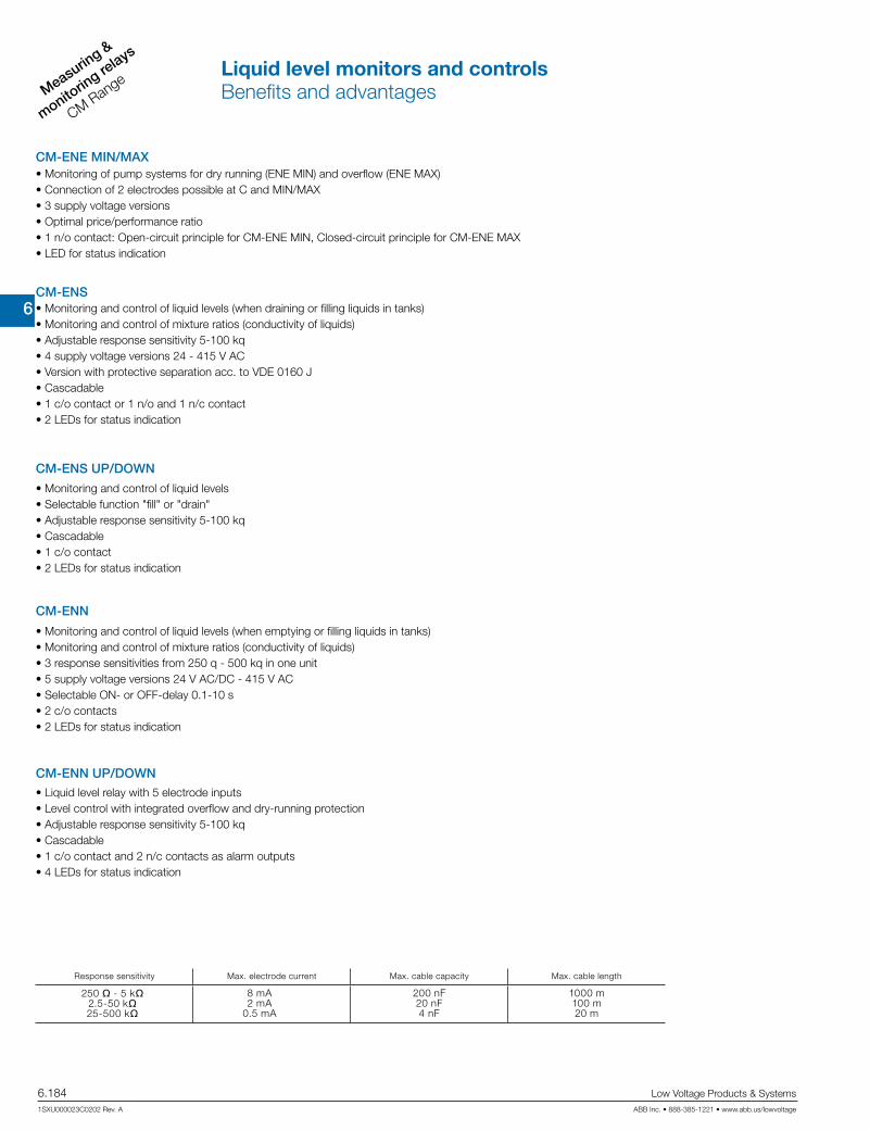
6
Measuring &
monitorin
g relays
CM Range
6.184 Low Voltage Products & Systems
1SXU000023C0202 Rev. A ABB Inc. • 888-385-1221 • www.abb.us/lowvoltage
• Monitoring of pump systems for dry running (ENE MIN) and overflow (ENE MAX)• Connection of 2 electrodes possible at C and MIN/MAX• 3 supply voltage versions• Optimal price/performance ratio• 1 n/o contact: Open-circuit principle for CM-ENE MIN, Closed-circuit principle for CM-ENE MAX• LED for status indication
• Monitoring and control of liquid levels (when draining or filling liquids in tanks)• Monitoring and control of mixture ratios (conductivity of liquids)• Adjustable response sensitivity 5-100 kq• 4 supply voltage versions 24 - 415 V AC• Version with protective separation acc. to VDE 0160 J• Cascadable• 1 c/o contact or 1 n/o and 1 n/c contact• 2 LEDs for status indication
• Monitoring and control of liquid levels • Selectable function "fill" or "drain"• Adjustable response sensitivity 5-100 kq• Cascadable• 1 c/o contact• 2 LEDs for status indication
• Monitoring and control of liquid levels (when emptying or filling liquids in tanks)• Monitoring and control of mixture ratios (conductivity of liquids)• 3 response sensitivities from 250 q - 500 kq in one unit• 5 supply voltage versions 24 V AC/DC - 415 V AC• Selectable ON- or OFF-delay 0.1-10 s• 2 c/o contacts• 2 LEDs for status indication
CM-ENE MIN/MAX
CM-ENN
CM-ENN UP/DOWN
CM-ENS
CM-ENS UP/DOWN
• Liquid level relay with 5 electrode inputs• Level control with integrated overflow and dry-running protection• Adjustable response sensitivity 5-100 kq• Cascadable• 1 c/o contact and 2 n/c contacts as alarm outputs• 4 LEDs for status indication
Response sensitivity Max. electrode current Max. cable capacity Max. cable length
250 q - 5 kq2.5-50 kq25-500 kq
8 mA2 mA
0.5 mA
200 nF20 nF4 nF
1000 m100 m20 m
Liquid level monitors and controlsBenefits and advantages

6
Measuring &
monitoring relays
CM Range
Low Voltage Products & Systems 6.185ABB Inc. • 888-385-1221 • www.abb.us/lowvoltage 1SXU000023C0202 Rev. A
Description
ABB‘s liquid level monitoring relays for regulation and control of liquid levels and ratios of mix-tures of conductive fluids.The assortment includes single function and multifunction monitoring relays which can be used for over flow and dry-running protection, for filling and draining applications, for max and min alarm or any combination of such functions. Furthermore, a wide range of accessories is available.
Ordering details
Rated control supply voltage
Referencecode
Catalognumber
Weight(1 pce) kg (lb)
24 V AC
CM-ENE MIN
1SVR550855R9500 0.15 (0.33)
110-130 V AC 1SVR550850R9500 0.15 (0.33)
220-240 V AC 1SVR550851R9500 0.15 (0.33)
24 V AC
CM-ENE MAX
1SVR550855R9400 0.15 (0.33)
110-130 V AC 1SVR550850R9400 0.15 (0.33)
220-240 V AC 1SVR550851R9400 0.15 (0.33)
24 V AC
CM-ENS
1SVR430851R9100 0.15 (0.33)
110-130 V AC 1SVR430851R0100 0.15 (0.33)
220-240 V AC 1SVR430851R1100 0.15 (0.33)
380-415 V AC 1SVR430851R2100 0.15 (0.33)
220-240 V AC 1) 1SVR430851R1300 0.15 (0.33)
24 V ACCM-ENS UP/DOWN
1SVR430851R9200 0.15 (0.33)
110-130 V AC 1SVR430851R0200 0.15 (0.33)
220-240 V AC 1SVR430851R1200 0.15 (0.33)
24-240 V AC/DC
CM-ENN
1SVR450055R0000 0.30 (0.66)
24 V AC 1SVR450059R0000 0.30 (0.66)
110-130 V AC 1SVR450050R0000 0.30 (0.66)
220-240 V AC 1SVR450051R0000 0.30 (0.66)
380-415 V AC 1SVR450052R0000 0.30 (0.66)
24 V AC
CM-ENN UP/DOWN
1SVR450059R0100 0.15 (0.33)
110-130 V AC 1SVR450050R0100 0.15 (0.33)
220-240 V AC 1SVR450051R0100 0.15 (0.33)
380-415 V AC 1SVR450052R0100 0.15 (0.33)
CM-ENE MIN
CM-ENE MAX
CM-ENS
CM-ENN
1) Version with protective separation acc. to VDE 0160, 1 n/o, 1 n/c
Suitable for Not suitable for
spring water acids, bases chemically pure water ethylene glycoldrinking water liquid fertilizers fuel concentrated alcoholsea water milk, beer, coffee oils paraffinsewage non-concentrated alcohol explosive areas (liquid gas) lacquers
Liquid level monitors are
Liquid level monitors and controlsOrdering details
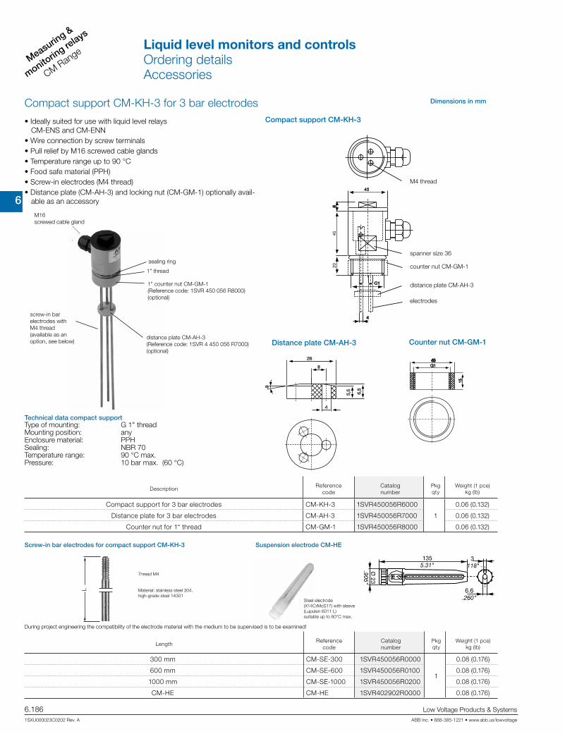
6
Measuring &
monitorin
g relays
CM Range
6.186 Low Voltage Products & Systems
1SXU000023C0202 Rev. A ABB Inc. • 888-385-1221 • www.abb.us/lowvoltage
L
1" thread
Compact support CM-KH-3 for 3 bar electrodes
sealing ring
1" counter nut CM-GM-1 (Reference code: 1SVR 450 056 R8000) (optional)
distance plate CM-AH-3 (Reference code: 1SVR 4 450 056 R7000) (optional)
Suspension electrode CM-HE
Steel electrode (X14CrMoS17) with sleeve (Lupulen 6011 L) suitable up to 60°C max.
M16 screwed cable gland
screw-in bar electrodes with M4 thread(available as an option, see below)
• Ideally suited for use with liquid level relays CM-ENS and CM-ENN
• Wire connection by screw terminals• Pull relief by M16 screwed cable glands• Temperature range up to 90 °C• Food safe material (PPH)• Screw-in electrodes (M4 thread)• Distance plate (CM-AH-3) and locking nut (CM-GM-1) optionally avail-
able as an accessory
Dimensions in mm
spanner size 36
electrodes
distance plate CM-AH-3
counter nut CM-GM-1
M4 thread
Compact support CM-KH-3
Counter nut CM-GM-1Distance plate CM-AH-3
Technical data compact supportType of mounting: G 1" thread Mounting position: any Enclosure material: PPH Sealing: NBR 70 Temperature range: 90 °C max. Pressure: 10 bar max. (60 °C)
Screw-in bar electrodes for compact support CM-KH-3
Thread M4
Material: stainless steel 304, high-grade steel 14301
During project engineering the compatibility of the electrode material with the medium to be supervised is to be examined!
DescriptionReference
codeCatalognumber
Pkg qty
Weight (1 pce) kg (lb)
Compact support for 3 bar electrodes CM-KH-3 1SVR450056R6000
1
0.06 (0.132)
Distance plate for 3 bar electrodes CM-AH-3 1SVR450056R7000 0.06 (0.132)
Counter nut for 1“ thread CM-GM-1 1SVR450056R8000 0.06 (0.132)
LengthReference
codeCatalognumber
Pkg qty
Weight (1 pce) kg (lb)
300 mm CM-SE-300 1SVR450056R0000
1
0.08 (0.176)
600 mm CM-SE-600 1SVR450056R0100 0.08 (0.176)
1000 mm CM-SE-1000 1SVR450056R0200 0.08 (0.176)
CM-HE CM-HE 1SVR402902R0000 0.08 (0.176)
Liquid level monitors and controlsOrdering detailsAccessories

6
Measuring &
monitoring relays
CM Range
Low Voltage Products & Systems 6.187ABB Inc. • 888-385-1221 • www.abb.us/lowvoltage 1SXU000023C0202 Rev. A
"DOWN"
"UP"
11-1411-12
Max.
Min.
C
11-1411-12
A1-A2
Function diagram CM-ENS UP/DOWN
If a metal tank is used, the ground reference electrode C is not required. In this case the cable can be connected directly to the metal surface of the tank.
AL2MAXMINAL1C
21-22
31-32
11-1411-1211-14 11-12
"DOWN"
"UP"
A1-A2
Function diagram CM-ENN UP/DOWN
The CM-ENS monitors levels of conductive liquids and is used for example for liquid level control in pump systems. It can be used for filling or draining tanks for example. It is also suitable for monitoring the conductivity of liquids. The measuring principle is based on the resistance change sensed by sin-gle-pole electrodes. After the supply voltage is applied to the terminals A1 and A2, the output relay is de-energized. The probes must be connected to C, MAX, MIN. The output relay energizes if the liquid exceeds the maximum level (C and MAX wet) and de-energizes if the liquid level is below the mini-mum level (MAX and MIN dry). Based on the measuring circuit there will be a response delay of approx. 250 ms at maximum sensitivity. Different levels in one tank can be controlled by up to 5 CM-ENS without interfering with each other.
Max.
Min.
C
11-14 11-12
A1-A2
Function diagram CM-ENS
The CM-ENS UP/DOWN monitors levels of conductive liquids and other media, and is used e.g. for liquid level control in pump systems. The measuring principle is based on the resistance change sensed by single-pole electrodes. The output relay functions fill (UP) or drain (DOWN) can be selected on a front-face selector switch. If the "UP" function is selected, the output relay is energized until the MAX electrode becomes wet. Then it is de-energized and not re-energized until the MIN electrode becomes dry. If the "DOWN" function is selected, the output relay is energized as soon as the MAX electrode becomes wet. It remains energized until the liquid level has dropped below the MIN electrode. The electrodes can be connected to more than one CM-ENS unit without interference.
The CM-ENN UP/DOWN monitors levels of conductive liquids and media and is used e.g. for liquid level control in pump systems. The measuring prin-ciple is based on the resistance change sensed by single-pole electrodes. The function of the output relay 11-12/14 can be selected by a selector switch on the front of the unit to fill "UP" or drain "DOWN". If the "UP" function is selected, the output relay is energized until the MAX electrode becomes wet. Then it is de-energized and not re-energized until the MIN electrode becomes dry.If the "DOWN" function is selected, the output relay is energized as soon as the MAX electrode becomes wet. It remains energized until the liquid level has dropped below the MIN electrode. The electrode inputs AL1 and AL2 energize/de-energize the corresponding output relays RAL1 (21-22) and RAL2 (31-32). AL1 opens if contact RAL1 (21-22) is wet. AL2 closes if con-tact RAL2 (31-32) is wet. This way, two additional alarm outputs for exceeding or dropping below the normal level can be implemented in addition to the filling levels MAX and MIN.
Liquid level monitors and controlsFunction diagrams
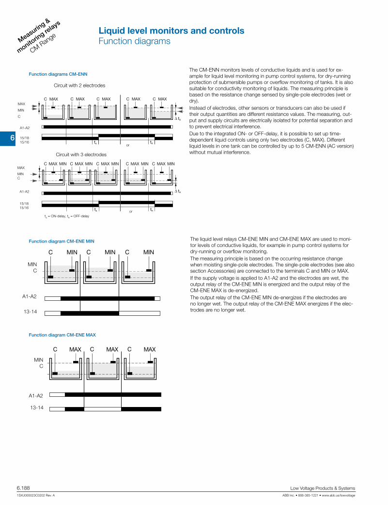
6
Measuring &
monitorin
g relays
CM Range
6.188 Low Voltage Products & Systems
1SXU000023C0202 Rev. A ABB Inc. • 888-385-1221 • www.abb.us/lowvoltage
Function diagram CM-ENE MIN
A1-A2
13-14
MIN C
Function diagram CM-ENE MAX
A1-A2
13-14
MIN C
MAX
MIN
C
Circuit with 2 electrodes
or
15/18 15/16
A1-A2
tA = ON-delay, tR = OFF-delay
Circuit with 3 electrodes
or
MAX
MIN C
15/18 15/16
A1-A2
Function diagrams CM-ENN
The liquid level relays CM-ENE MIN and CM-ENE MAX are used to moni-tor levels of conductive liquids, for example in pump control systems for dry-running or overflow monitoring. The measuring principle is based on the occurring resistance change when moisting single-pole electrodes. The single-pole electrodes (see also section Accessories) are connected to the terminals C and MIN or MAX. If the supply voltage is applied to A1-A2 and the electrodes are wet, the output relay of the CM-ENE MIN is energized and the output relay of the CM-ENE MAX is de-energized. The output relay of the CM-ENE MIN de-energizes if the electrodes are no longer wet. The output relay of the CM-ENE MAX energizes if the elec-trodes are no longer wet.
The CM-ENN monitors levels of conductive liquids and is used for ex-ample for liquid level monitoring in pump control systems, for dry-running protection of submersible pumps or overflow monitoring of tanks. It is also suitable for conductivity monitoring of liquids. The measuring principle is based on the resistance change sensed by single-pole electrodes (wet or dry). Instead of electrodes, other sensors or transducers can also be used if their output quantities are different resistance values. The measuring, out-put and supply circuits are electrically isolated for potential separation and to prevent electrical interference. Due to the integrated ON- or OFF-delay, it is possible to set up time-dependent liquid controls using only two electrodes (C, MAX). Different liquid levels in one tank can be controlled by up to 5 CM-ENN (AC version) without mutual interference.
Liquid level monitors and controlsFunction diagrams

6
Measuring &
monitoring relays
CM Range
Low Voltage Products & Systems 6.189ABB Inc. • 888-385-1221 • www.abb.us/lowvoltage 1SXU000023C0202 Rev. A
Connection diagram CM-ENS
1214 A2
CA1
MAX11
MINMIN 11MAXC
A2A1 12 14
A1 - A2 Rated control supply voltageC Ground reference electrodeMAX Maximum levelMIN Minimum level11-12/14 Output contacts - open-circuit or closed-circuit principle selectable
Connection diagram CM-ENS UP/DOWN
A1-A2 Rated control supply voltageC Ground reference electrodeMIN Min. level electrodeMAX Max. level electrode15-16/18 Output contacts - 25-26/28 open-circuit principle
Connection diagram CM-ENN
A1-A2 Rated control supply voltageC Ground reference electrodeMIN Minimum level13-14 Output contact - open-circuit principle
A1-A2 Rated control supply voltageC Ground reference electrodeMAX Max. level 13-14 Output contact - closed-circuit principle
Connection diagram CM-ENE MIN Connection diagram CM-ENE MAX
A1-A2 Rated control supply voltageC Ground reference electrodeMAX Maximum levelMIN Minimum level11(15)-12(16)/14(18) Output contacts - open-circuit principle
A1-A2 Rated control supply voltageC Ground reference electrodeMIN Minimum level electrodeMAX Maximum level electrode AL1 Alarm electrode 1 AL2 Alarm electrode 211-12/14 Output contacts - 21-22 open-circuit or closed-circuit 31-32 principle selectable
Connection diagram CM-ENN UP/DOWN
Liquid level monitors and controlsConnection diagrams

6
Measuring &
monitorin
g relays
CM Range
6.190 Low Voltage Products & Systems
1SXU000023C0202 Rev. A ABB Inc. • 888-385-1221 • www.abb.us/lowvoltage
Application examples CM-ENE MIN/MAX
CM-ENE MIN CM-ENE MAX CM-ENE MIN und CM-ENE MAX
CascadingThe electrode inputs can be interconnected as required, which ensures simple monitoring of different liquid levels.
RedundancyRedundant liquid level monitoring or control can be implemented by connecting the electrodes to two units.
This makes the application much safer.
Application examples CM-ENS
fill drain
Liquid level control - fill - switch position "UP"
Liquid level control - drain - switch position "DOWN"
Application examples CM-ENS UP/DOWN
Cascading of electrodesThe electrode inputs can be interconnected as required, which ensures simple monitoring of different liquid levels.
RedundancyRedundant liquid level monitoring or control can be implemented by con-necting the electrodes to two units.
This makes the application much safer.
Liquid level monitors and controlsApplication examples
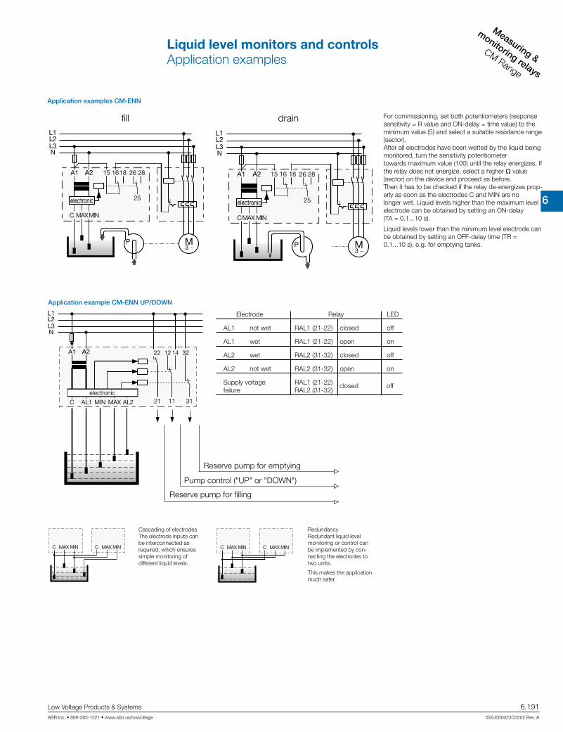
6
Measuring &
monitoring relays
CM Range
Low Voltage Products & Systems 6.191ABB Inc. • 888-385-1221 • www.abb.us/lowvoltage 1SXU000023C0202 Rev. A
fill drain
Application examples CM-ENN
For commissioning, set both potentiometers (response sensitivity = R value and ON-delay = time value) to the minimum value (5) and select a suitable resistance range (sector). After all electrodes have been wetted by the liquid being monitored, turn the sensitivity potentiometer towards maximum value (100) until the relay energizes. If the relay does not energize, select a higher q value (sector) on the device and proceed as before. Then it has to be checked if the relay de-energizes prop-erly as soon as the electrodes C and MIN are no longer wet. Liquid levels higher than the maximum level electrode can be obtained by setting an ON-delay (TA = 0.1...10 s).
Liquid levels lower than the minimum level electrode can be obtained by setting an OFF-delay time (TR = 0.1...10 s), e.g. for emptying tanks.
Application example CM-ENN UP/DOWN
Cascading of electrodesThe electrode inputs can be interconnected as required, which ensures simple monitoring of different liquid levels.
RedundancyRedundant liquid level monitoring or control can be implemented by con-necting the electrodes to two units.
This makes the application much safer.
Electrode Relay LED
AL1 not wet RAL1 (21-22) closed off
AL1 wet RAL1 (21-22) open on
AL2 wet RAL2 (31-32) closed off
AL2 not wet RAL2 (31-32) open on
Supply voltage RAL1 (21-22) failure RAL2 (31-32) closed off
Reserve pump for emptying
Pump control ("UP" or "DOWN")
Reserve pump for filling
Liquid level monitors and controlsApplication examples
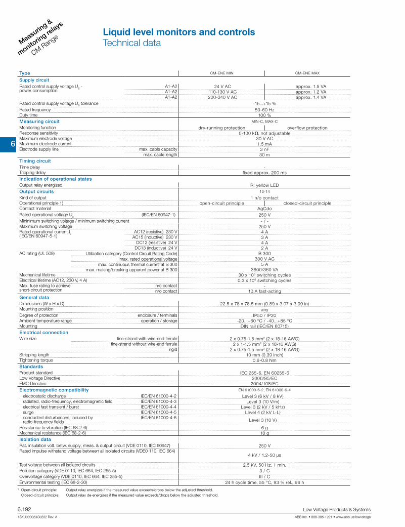
6
Measuring &
monitorin
g relays
CM Range
6.192 Low Voltage Products & Systems
1SXU000023C0202 Rev. A ABB Inc. • 888-385-1221 • www.abb.us/lowvoltage
Type CM-ENE MIN CM-ENE MAX
Supply circuitRated control supply voltage US - power consumption
A1-A2 24 V AC approx. 1.5 VAA1-A2 110-130 V AC approx. 1.2 VAA1-A2 220-240 V AC approx. 1.4 VA
Rated control supply voltage US tolerance -15...+15 %Rated frequency 50-60 HzDuty time 100 %Measuring circuit MIN-C, MAX-C
Monitoring function dry-running protection overflow protectionResponse sensitivity 0-100 kq, not adjustableMaximum electrode voltage 30 V ACMaximum electrode current 1.5 mAElectrode supply line max. cable capacity 3 nF
max. cable length 30 mTiming circuitTime delay -Tripping delay fixed approx. 200 msIndication of operational statesOutput relay energized R: yellow LEDOutput circuits 13-14
Kind of output 1 n/o contactOperational principle 1) open-circuit principle closed-circuit principleContact material AgCdoRated operational voltage Ue (IEC/EN 60947-1) 250 VMininimum switching voltage / minimum switching current - / -Maximum switching voltage 250 VRated operational current Ie(IEC/EN 60947-5-1)
AC12 (resistive) 230 V 4 AAC15 (inductive) 230 V 3 A
DC12 (resistive) 24 V 4 ADC13 (inductive) 24 V 2 A
AC rating (UL 508) Utilization category (Control Circuit Rating Code) B 300max. rated operational voltage 300 V AC
max. continuous thermal current at B 300 5 Amax. making/breaking apparent power at B 300 3600/360 VA
Mechanical lifetime 30 x 106 switching cyclesElectrical lifetime (AC12, 230 V, 4 A) 0.3 x 10⁶ switching cyclesMax. fuse rating to achieveshort-circuit protection
n/c contact -n/o contact 10 A fast-acting
General dataDimensions (W x H x D) 22.5 x 78 x 78.5 mm (0.89 x 3.07 x 3.09 in)Mounting position anyDegree of protection enclosure / terminals IP50 / IP20Ambient temperature range operation / storage -20...+60 °C / -40...+85 °CMounting DIN rail (IEC/EN 60715)Electrical connectionWire size fine-strand with wire-end ferrule 2 x 0.75-1.5 mm2 (2 x 18-16 AWG)
fine-strand without wire-end ferrule 2 x 1-1.5 mm2 (2 x 18-16 AWG)rigid 2 x 0.75-1.5 mm2 (2 x 18-16 AWG)
Stripping length 10 mm (0.39 inch)Tightening torque 0.6-0.8 NmStandardsProduct standard IEC 255-6, EN 60255-6Low Voltage Directive 2006/95/ECEMC Directive 2004/108/ECElectromagnetic compatibility EN 61000-6-2, EN 61000-6-4
electrostatic discharge IEC/EN 61000-4-2 Level 3 (6 kV / 8 kV)radiated, radio-frequency, electromagnetic field IEC/EN 61000-4-3 Level 3 (10 V/m)electrical fast transient / burst IEC/EN 61000-4-4 Level 3 (2 kV / 5 kHz)surge IEC/EN 61000-4-5 Level 4 (2 kV L-L)conducted disturbances, induced by radio-frequency fields
IEC/EN 61000-4-6 Level 3 (10 V)
Resistance to vibration (IEC 68-2-6) 6 gMechanical resistance (IEC 68-2-6) 10 gIsolation dataRat. insulation volt. betw. supply, meas. & output circuit (VDE 0110, IEC 60947) 250 V Rated impulse withstand voltage between all isolated circuits (VDE0 110, IEC 664)
4 kV / 1.2-50 µs
Test voltage between all isolated circuits 2.5 kV, 50 Hz, 1 min.Pollution category (VDE 0110, IEC 664, IEC 255-5) 3 / COvervoltage category (VDE 0110, IEC 664, IEC 255-5) III / CEnvironmental testing (IEC 68-2-30) 24 h cycle time, 55 °C, 93 % rel., 96 h
1) Open-circuit principle: Output relay energizes if the measured value exceeds/drops below the adjusted threshold. Closed-circuit principle: Output relay de-energizes if the measured value exceeds/drops below the adjusted threshold.
Liquid level monitors and controlsTechnical data

6
Measuring &
monitoring relays
CM Range
Low Voltage Products & Systems 6.193ABB Inc. • 888-385-1221 • www.abb.us/lowvoltage 1SXU000023C0202 Rev. A
Type CM-ENS CM ENS UP/DOWN
Supply circuitRated control supply voltage US - power consumption
A1-A2 24 V AC 24 V ACA1-A2 110-130 V AC approx. 1.5 VA 110-130 V AC approx. 4 VAA1-A2 220-240 V AC approx. 1.5 VA 220-240 V AC approx. 4 VAA1-A2 380-415 V AC approx. 1.5 VA
Rated control supply voltage US tolerance -15...+10 %Rated frequency 50-60 HzDuty time 100 % Measuring circuit MAX-MIN-C
Monitoring function liquid level controlResponse sensitivity 5-100 kq, adjustableMaximum electrode voltage 30 V ACMaximum electrode current 1 mAElectrode supply line max. cable capacity 10 nF
max. cable length 100 m Timing circuitTime delay -Tripping delay approx. 250 msIndication of operational statesControl supply voltage U: green LEDOutput relay energized R MAX/MIN: yellow LEDAlarm relay AL1 - R AL1: yellow LEDAlarm relay AL2 - R AL2: yellow LEDOutput circuits 11-12/14, 21-22, 31-32
Kind of output 1 c/o contact, 1 n/o + 1 n/c contact 2)Operational principle 1) open-circuit principle open- and closed-circuit principleContact material AgCdoRated operational voltage Ue (IEC/EN 60947-1) 250 VMinimum switching voltage / minimum switching current - / -Maximum switching voltage 250 VRated operational current Ie (IEC/EN 60947-5-1)
AC12 (resistive) 230 V 4 AAC15 (inductive) 230 V 3 A
DC12 (resistive) 24 V 4 ADC13 (inductive) 24 V 2 A
AC rating (UL 508) Utilization category (Control Circuit Rating Code) B 300max. rated operational voltage 300 V AC
max. continuous thermal current at B 300 5 Amax. making/breaking apparent power at B 300 3600/360 VA
Mechanical lifetime 30 x 106 switching cyclesElectrical lifetime (AC12, 230 V, 4 A) 0.3 x 10⁶ switching cyclesMax. fuse rating to achieve short-circuit protection n/c / n/o contact 10 A fast-acting / 10 A fast-acting
General dataDimensions (W x H x D) 22.5 x 70 x 100 mm (0.89 x 3.07 x 3.94 in)Mounting position anyDegree of protection enclosure / terminals IP50 / IP20Ambient temperature range operation / storage -20...+60 °C / -40...+85 °CMounting DIN rail (IEC/EN 60715)Electrical connectionWire size fine-strand with wire end ferrule 2 x 2.5 mm2 (2 x 14 AWG)StandardsProduct standard IEC 255-6, EN 60255-6Low Voltage Directive 2006/95/EGEMC Directive 2004/108/EGElectromagnetic compatibility -
electrostatic discharge IEC/EN 61000-4-2 Level 3 (6 kV / 8kV)radiated, radio-frequency, electromagnetic field IEC/EN 61000-4-3 Level 3 (10 V/m)electrical fast transient / burst IEC/EN 61000-4-4 Level 3 (2 kV / 5 kHz)surge IEC/EN 61000-4-5 Level 4 (2 kV L-L)conducted disturbances, induced byradio-frequency fields
IEC/EN 61000-4-6 Level 3 (10 V)
Resistance to vibration (IEC 68-2-6) 4 gMechanical resistance (IEC 68-2-6) 6 gIsolation dataRated insulation voltage between supply, measuring and output circuit (VDE 0110, IEC 60947) 250 V
Rated impulse withstand voltage between all isolated circuits (VDE0 110, IEC 664) 4 kV / 1.2 - 50 µsTest voltage between all isolated circuits 2,5 kV, 50 Hz, 1 min.Pollution category (VDE 0110, IEC 664, IEC 255-5) 3 / COvervoltage category (VDE 0110, IEC 664, IEC 255-5) III / CEnvironmental testing (IEC 68-2-30) 24 h cycle time, 55 °C, 93 % rel., 96 h
1) Open-circuit principle: Output relay energizes if the measured value exceeds/drops below the adjusted threshold. Closed-circuit principle: Output relay de-energizes if the measured value exceeds/drops below the adjusted threshold. 2) 1SVR 430 851 R1300 (version with safe isolation)
Liquid level monitors and controlsTechnical data

6
Measuring &
monitorin
g relays
CM Range
6.194 Low Voltage Products & Systems
1SXU000023C0202 Rev. A ABB Inc. • 888-385-1221 • www.abb.us/lowvoltage
Type CM-ENN UP/DOWN CM-ENN
Supply circuitRated control supply voltage US - power consumption A1-A2 24 V AC 24 V AC
A1-A2 110-130 V AC approx. 1.5 VA 110-130 V AC approx. 2.5 VAA1-A2 220-240 V AC approx. 1.5 VA 220-240 V AC approx. 3 VAA1-A2 380-415 V AC approx. 1.5 VA 380-415 V ACapprox. 4 VAA1-A2 24-240 V AC/DC approx. 2 VA/W
Rated control supply voltage US tolerance -15...+10 %Rated frequency 50-60 Hz 50-60 Hz oder DCDuty time 100 %Measuring circuit MAX-MIN-C
Monitoring function liquid level controlResponse sensitivity adjustable adjustable
5-100 kq 250 q - 5 kq 2.5-50 kq 25-500 kqMaximum electrode voltage 30 V AC 20 V ACMaximum electrode current 1 mA 8 mA 2 mA 0.5 mAElectrode supply line max. cable capacity 10 nF 200 nF 20 nF 4 nF
max. cable length 100 m 1000 m 100 m 20 mTiming circuitTime delay - 0.1-10 s, adjustable, ON- or OFF-delayTripping delay approx. 250 ms -Indication of operational statesControl supply voltage U: green LEDOutput relay energized R MAX/MIN: yellow LED R: yellow LEDOutput circuits 11-12/14, 21-22, 31-32 15-16/18, 25-26/28
Kind of output 1 c/o + 2 n/c contacts 2 c/o contactsOperational principle 1) open-circuit principle open- and closed-circuit principleContact material AgCdoRated operational voltage Ue IEC/EN 60947-1 250 V 400 VMinimum switching voltage / minimum switching current - / -Maximum switching voltage 250 V 400 VRated operational current Ie(IEC/EN 60947-5-1)
AC12 (resistive) 230 V 4 A 5 AAC15 (inductive) 230 V 3 A
DC12 (resistive) 24 V 4 A 5 ADC13 (inductive) 24 V 2 A 2.5 A
AC rating (UL 508) Utilization category (Control Circuit Rating Code) B 300max. rated operational voltage 300 V AC
max. continuous thermal current at B 300 5 Amax. making/breaking apparent power at B 300 3600/360 VA
Mechanical lifetime 30 x 106 switching cyclesElectrical lifetime (AC12, 230 V, 4 A) 0.3 x 10⁶ switching cycles 0.1 x 10⁶ switching cyclesMax. fuse rating to achieve short-circuit protection n/c / n/o contact 4 A fast-acting / 6 A fast-actingGeneral dataDiemensions (W X H X D) 45 x 78 x 100 mm (1.77 x 3.07 x 3.94 in)Mounting position anyDegree of protection enclosure / terminals IP50 / IP20Ambient temperature range operation / storage -25...+65 °C / -40...+85 °CMounting DIN rail (IEC/EN 60715)Electrical connectionWire size fine-strand with wire end ferrule 2 x 2.5 mm2 (2 x 14 AWG)StandardsProduct standard IEC 255-6, EN 60255-6Low Voltage Directive 2006/95/EGEMC Directive 2004/108/EGElectromagnetic compatibility -
electrostatic discharge IEC/EN 61000-4-2 Level 3 (6 kV / 8kV)radiated, radio-frequency, electromagnetic field IEC/EN 61000-4-3 Level 3 (10 V/m)electrical fast transient / burst IEC/EN 61000-4-4 Level 3 (2 kV / 5 kHz)surge IEC/EN 61000-4-5 Level 4 (2 kV L-L)conducted disturbances, induced by radio-frequency fields
IEC/EN 61000-4-6 Level 3 (10 V)
Resistance to vibration (IEC 68-2-6) 5 gMechanical resistance (IEC 68-2-6) 10 gIsolation dataRated insulation voltage between supply, measuring and output circuit(VDE 0110, IEC 60947) 250 V 500 V
Rated impulse withstand voltage between all isolated circuits (VDE0 110, IEC 664) 4 kV / 1.2 - 50 µsTest voltage between all isolated circuits 2,5 kV, 50 Hz, 1 min.Pollution category (VDE 0110, IEC 664, IEC 255-5) 3 / COvervoltage category (VDE 0110, IEC 664, IEC 255-5) III / CEnvironmental testing (IEC 68-2-30) 24 h cycle time, 55 °C, 93 % rel., 96 h
1) Open-circuit principle: Output relay energizes if the measured value exceeds/drops below the adjusted threshold. Closed-circuit principle: Output relay de-energizes if the measured value exceeds/drops below the adjusted threshold.
Liquid level monitors and controlsTechnical data
6
Measuring &
monitoring relays
CM Range
Low Voltage Products & Systems 6.195ABB Inc. • 888-385-1221 • www.abb.us/lowvoltage 1SXU000023C0202 Rev. A
Contact protection & sensor interface relays
Con
tact
pro
tect
ion
&
sens
or in
terfa
ce re
lays

6
Measuring &
monitorin
g relays
CM Range
6.196 Low Voltage Products & Systems
1SXU000023C0202 Rev. A ABB Inc. • 888-385-1221 • www.abb.us/lowvoltage
Description
Contact protection relay:The CM-KRN protects sensitive control contacts from excessive load. It can be used with latching function or without. Bounce time of control contacts can be bypassed by the adjust-able response delay time. Use for contact protection.
Contact protection relay:The CM-SIS is used to supply 2- or 3-wire NPN or PNP sensors with power and to evaluate their switching signals. Two sensors of the types NPN or PNP can be connected simultane-ously. Selection is done via the front-face rotary switch.
Ordering details
Rated control supply voltage Timing circuitReference
codeCatalognumber
Weight(1 pce) kg (lb)
24 V AC
0.05-30 s
CM-KRN
1SVR450089R0000 0.30 (0.66)
110-130 V AC 1SVR450080R0000 0.30 (0.66)
220-240 V AC 1SVR450081R0000 0.30 (0.66)
380-415 V AC 1SVR450082R0000 0.30 (0.66)
24 V AC 1SVR450099R0000 0.30 (0.66)
110-130 V AC 1SVR450090R0000 0.30 (0.66)
220-240 V AC 1SVR450091R0000 0.30 (0.66)
24 V AC/DC1) 1SVR450099R1000 0.30 (0.66)
110-240 V AC / 105-260 V DC2) CM-SIS 1SVR430500R2300 0.22 (0.48)
CM-KRN
CM-SIS
Characteristics CM-SISCharacteristics CM-KRN
• High efficiency• Low heating• Wide range of supply voltage• Constant output voltage 24 V DC• Safe isolation acc. to EN 50178 (VDE
0160)• Short-circuit and overload proof• Input protected by internal fuse• 2 x 1 c/o contact• 3 LEDs for status indication
• Protects and reduces load from sen-sitive control contacts
• Adjustable ON-delay 0.05-30 s
• Acts as two-position switch• Stores switch positions• Electrically isolated circuits• 2 c/o contacts• 2 LEDs for status indication
1) Not electrically isolated2) Safe isolation, short circuit and overload proof
Contact protection and sensor interface relaysOrdering details
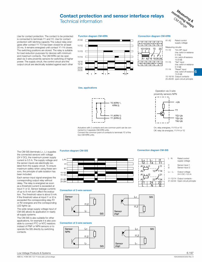
6
Measuring &
monitoring relays
CM Range
Low Voltage Products & Systems 6.197ABB Inc. • 888-385-1221 • www.abb.us/lowvoltage 1SXU000023C0202 Rev. A
Function diagram CM-KRN
Use, applications
A1-A2 Rated control supply voltage
Measuring circuits:Y1-Y2 "On-Off" input
(max. switch-on resistance 6-10 kq, min. switch-off resistance 15-20 kq)
Y1-Y3 "Set" input (max. switch-on resistance 6-10 kq)
Y1-Y4 "Reset" input (max. switch-off resistance 15-20 kq)
15-16/18 Output contacts -25-26/28 open-circuit principle
A1/A2
Y1/Y2
Y1/Y3
Y1/Y4
15/18 15/16
25/28 25/26
Operation via 3-wire proximity sensors NPN
On; relay energizes, Y1/Y3 or Y2Off; relay de-energizes, Y1/Y4 or Y2
Actuators with 2 contacts and one common point can be con-nected to 2 separate CM-KRN units.Connect the common point of contacts to terminals Y2 of the two CM-KRN units.
Connection diagram CM-KRN
A1 I1
A2A1 I2
A2
11
12 14
2422
21
Function diagram CM-SIS
L - N Rated control supply voltage
I1 Sensor input 1I2 Sensor input 2
L+ - L- Output voltage 24 V DC / 0.5 A
11-12/14 Output contacts -21-22/24 Open-circuit principle
Connection of 2-wire sensors
Connection of 3-wire sensors
Connection diagram CM-SIS
Use for contact protection. The contact to be protected is connected to terminals Y1 and Y2. Use for contact protection with latching capacity The output relay ener-gizes after contact Y1-Y3 has been closed for at least 20 ms. It remains energized until contact Y1-Y4 closes. The switching positions are stored. The relay is suitable for load reduction purposes for devices with minimum and maximum contacts. The CM-KRN can be oper-ated via 3-wire proximity sensors for switching of higher power. The supply circuit, the control circuit and the output circuit are electrically isolated against each other
The CM-SIS (terminals L+, L-) supplies the connected sensors with voltage (24 V DC), the maximum power supply current is 0.5 A. The supply voltage and the sensor inputs are electrically iso-lated from the supply circuit. To ensure maximum safety when using these sen-sors, the principle of safe isolation has been included.Each sensor input signal energizes the corresponding output relay without delay. The relay is energized as soon as a threshold current is exceeded at input I1 or I2. Sensor leakage currents of up to 8 mA don`t affect the evalua-tion. The threshold value is about 9 mA. If the threshold value at input I1 or I2 is exceeded the corresponding relay R1 or R2 energizes and the corresponding LED lights up.The wide-range supply voltage input of CM-SIS allows its application in nearly all supply systems.The CM-SIS is also suitable for other applications, for example it is also pos-sible to connect PTC or NTC resistors instead of PNP or NPN sensors or to operate the SIS directly by switching contacts.
Contact protection and sensor interface relaysTechnical information
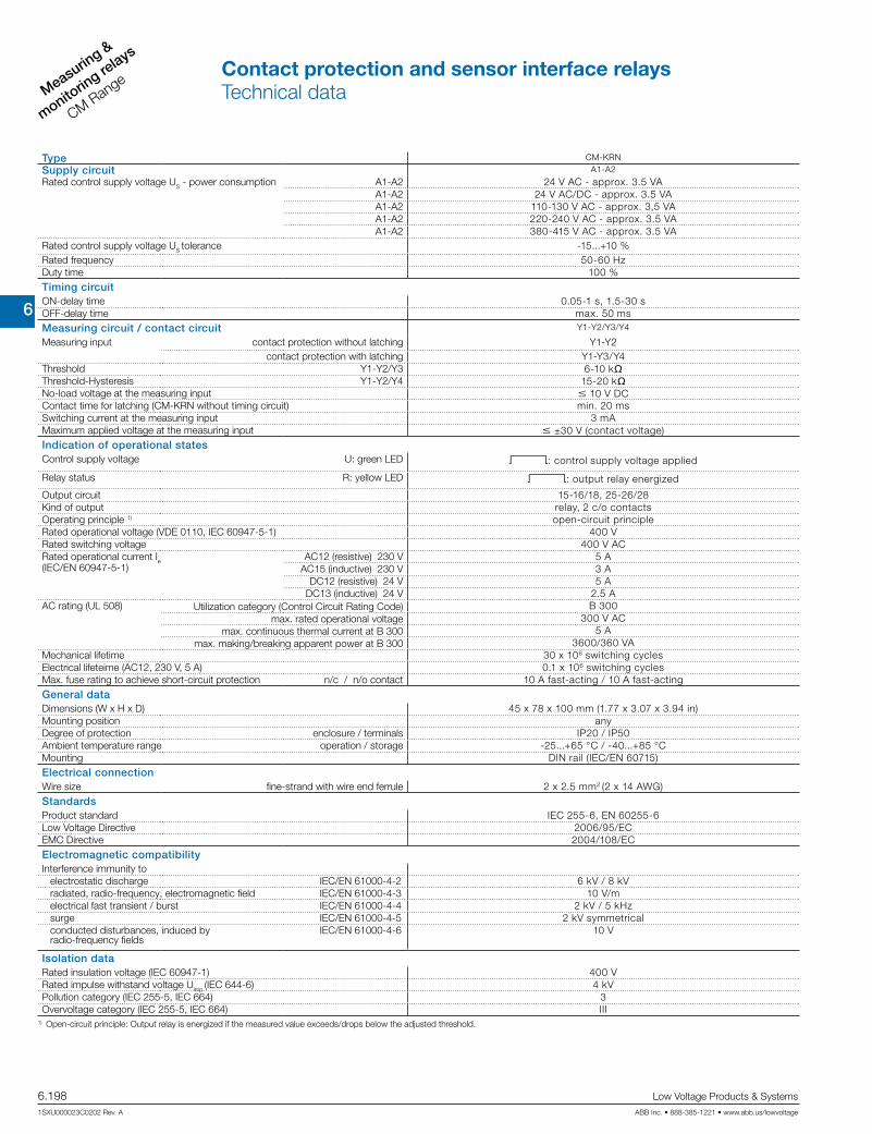
6
Measuring &
monitorin
g relays
CM Range
6.198 Low Voltage Products & Systems
1SXU000023C0202 Rev. A ABB Inc. • 888-385-1221 • www.abb.us/lowvoltage
Type CM-KRN
Supply circuit A1-A2
Rated control supply voltage US - power consumption A1-A2 24 V AC - approx. 3.5 VAA1-A2 24 V AC/DC - approx. 3.5 VAA1-A2 110-130 V AC - approx. 3,5 VAA1-A2 220-240 V AC - approx. 3.5 VAA1-A2 380-415 V AC - approx. 3.5 VA
Rated control supply voltage US tolerance -15...+10 % Rated frequency 50-60 HzDuty time 100 %Timing circuitON-delay time 0.05-1 s, 1.5-30 sOFF-delay time max. 50 msMeasuring circuit / contact circuit Y1-Y2/Y3/Y4
Measuring input contact protection without latching Y1-Y2contact protection with latching Y1-Y3/Y4
Threshold Y1-Y2/Y3 6-10 kqThreshold-Hysteresis Y1-Y2/Y4 15-20 kqNo-load voltage at the measuring input m 10 V DCContact time for latching (CM-KRN without timing circuit) min. 20 msSwitching current at the measuring input 3 mAMaximum applied voltage at the measuring input m ±30 V (contact voltage)Indication of operational states Control supply voltage U: green LED V: control supply voltage applied
Relay status R: yellow LED V: output relay energized
Output circuit 15-16/18, 25-26/28Kind of output relay, 2 c/o contactsOperating principle 1) open-circuit principleRated operational voltage (VDE 0110, IEC 60947-5-1) 400 VRated switching voltage 400 V ACRated operational current Ie (IEC/EN 60947-5-1)
AC12 (resistive) 230 V 5 AAC15 (inductive) 230 V 3 A
DC12 (resistive) 24 V 5 ADC13 (inductive) 24 V 2.5 A
AC rating (UL 508) Utilization category (Control Circuit Rating Code) B 300max. rated operational voltage 300 V AC
max. continuous thermal current at B 300 5 Amax. making/breaking apparent power at B 300 3600/360 VA
Mechanical lifetime 30 x 106 switching cyclesElectrical lifeteime (AC12, 230 V, 5 A) 0.1 x 10⁶ switching cyclesMax. fuse rating to achieve short-circuit protection n/c / n/o contact 10 A fast-acting / 10 A fast-actingGeneral dataDimensions (W x H x D) 45 x 78 x 100 mm (1.77 x 3.07 x 3.94 in)Mounting position anyDegree of protection enclosure / terminals IP20 / IP50Ambient temperature range operation / storage -25...+65 °C / -40...+85 °CMounting DIN rail (IEC/EN 60715)Electrical connectionWire size fine-strand with wire end ferrule 2 x 2.5 mm2 (2 x 14 AWG)StandardsProduct standard IEC 255-6, EN 60255-6Low Voltage Directive 2006/95/ECEMC Directive 2004/108/ECElectromagnetic compatibilityInterference immunity to
electrostatic discharge IEC/EN 61000-4-2 6 kV / 8 kVradiated, radio-frequency, electromagnetic field IEC/EN 61000-4-3 10 V/melectrical fast transient / burst IEC/EN 61000-4-4 2 kV / 5 kHzsurge IEC/EN 61000-4-5 2 kV symmetricalconducted disturbances, induced by radio-frequency fields
IEC/EN 61000-4-6 10 V
Isolation dataRated insulation voltage (IEC 60947-1) 400 VRated impulse withstand voltage Uimp (IEC 644-6) 4 kVPollution category (IEC 255-5, IEC 664) 3Overvoltage category (IEC 255-5, IEC 664) III
1) Open-circuit principle: Output relay is energized if the measured value exceeds/drops below the adjusted threshold.
Contact protection and sensor interface relaysTechnical data

6
Measuring &
monitoring relays
CM Range
Low Voltage Products & Systems 6.199ABB Inc. • 888-385-1221 • www.abb.us/lowvoltage 1SXU000023C0202 Rev. A
Type CM-SIS
Input circuitSupply voltage L-N AC 110-240 V AC (-15...+10 %)
DC 110-240 V (max. 105-260 V DC)Frequency, AC supply 47-440 HzSupply voltage failure bridging time 10 ms min. at 100 % loadCurrent consumption max. 0.35 A
at 115 V AC 0.27 Aat 230 V AC 0.14 A
Inrush current at 25°C (m 2 ms) 33 A Internal input fuse 800 mA slow-actingMeasuring circuit L+, L- / I1, I2
Sensor voltage L+ L- 24 V DC ± 3%Sensor current / power max. 0.5 A / 12 WResidual ripple max. 100 mVpp
Deviation with load change statical max. ± 0.5 %load change dynamical 10-90 % max. .5 %
change of the input voltage max. ± 0.5 %Short-circuit protection overcurrent switch-off with automatic restartOverload protection excess temperature and overcurrent switch-offReset after thermal overload switch-off automatic reset after cooling downSensor type connection possibilities I1, I2 2- or 3-wire connection, NPN or PNP selectable by front-face switchInput resistance approx. 2.5 kqThreshold value for relays R1, R2 Uemitter-collector < 2,3 V (I1, I2 > 8 mA) Maximum switching frequency approx. 20 HzOutput circuit 11-12/14, 21-22/24
Kind of output 2 relays, 1 c/o contact eachOperating principle 1) open-circuit principleRated operational voltage 250 VMaximum switching voltage 250 V ACRated operational current Ie (IEC/EN 60947-5-1)
AC12 (resistive) 230 V 4 AAC15 (inductive) 230 V 3 A
DC12 (resistive) 24 V 4 ADC13 (inductive) 24 V 2 A
AC rating (UL 508) Utilization category (Control Circuit Rating Code) B 300max. rated operational voltage 300 V AC
max. continuous thermal current at B 300 5 Amax. making/breaking apparent power at B 300 3600/360 VA
Mechanical lifetime 10 x 106 switching cyclesElectrical lifetime 0.1 x 10⁶ switching cyclesMax. fuse rating to achieve short-circuit protection n/c / n/o contact 6 A fast-acting / 10 A fast-actingIndication of operational statesControl supply voltage U: green LED V: control supply voltage appliedRelay status R1 R1: yellow LED V: threshold value at input I1 exceeded
Relay status R2 R2: yellow LED V: threshold value at input I2 exceeded
General dataEfficiency at rated load approx. 84 % (at 230 V AC)Ambient temperature range operation / storage 0...+55 °C / -25...+75 °CDimensions (W x H x D) 22.5 x 78 x 100 mm (0.89 x 3.07 x 3.94 in)Mounting position horizontallyMounting DIN rail (IEC/EN 60715)Minimum distance to other units left-hand side 10 mm (0.39 in), vertical distance 50 m (1.97 in)Electrical connectionWire size 2 x 2,5 mm2 (2 x 14 AWG)StandardsProduct standard IEC 255-6, EN 60255-6Electrical safety IEC(EN) 60255-5, EN 50178 (VDE 0160), EN60950, UL 508, CSA 22.2Galvanic isolation safe isolation between L+,L-, I1,I2, and L,N,11,12,14,21,22,24Electromagnetic compatibilityInterference immunity to EN 61000-6-2
electrostatic discharge IEC/EN 61000-4-2 Level 3 (6 / 8 kV)radiated, radio-frequency, electromagnetic field IEC/EN 61000-4-3 Level 3 (10 V/m)electrical fast transient / burst IEC/EN 61000-4-4 Level 4 (4 kV)surge IEC/EN 61000-4-5 Inst. class 3 (2 kV)conducted disturbances, induced by radio-frequency fields
IEC/EN 61000-4-6 Level 3 (10 V)
Interference immunity to EN 50081-2 radiated noise EN 55011, class BInput current harmonics no limitation
Isolation dataInsulation testing 2.5 kV AC (routine test), 3 kV AC (type test)Degree of pollution 2Overvoltage category II
Contact protection and sensor interface relaysTechnical information

6
Measuring &
monitorin
g relays
CM Range
6.200 Low Voltage Products & Systems
1SXU000023C0202 Rev. A ABB Inc. • 888-385-1221 • www.abb.us/lowvoltage
Notes

6
Measuring &
monitoring relays
CM Range
Low Voltage Products & Systems 6.201ABB Inc. • 888-385-1221 • www.abb.us/lowvoltage 1SXU000023C0202 Rev. A
Cycle monitoring relaywith watchdog function
Cyc
le m
onito
ring
rela
yw
/wat
chdo
g fu
nctio
n

6
Measuring &
monitorin
g relays
CM Range
6.202 Low Voltage Products & Systems
1SXU000023C0202 Rev. A ABB Inc. • 888-385-1221 • www.abb.us/lowvoltage
The cycle monitoring relay CM-WDS (watchdog) observes if a regularly intermittent pulse is ap-plied to its pulse input “I“. It is, for example, possible to connect the output of a programmable logic controller (plc), which is set and reset regularly (e. g. once each cycle). The connected cycle pulse must be generated by suitable programming of the plc/ipc. Now, the CM-WDS monitors if the cycle time of the plc/ipc program is smaller than the cycle monitoring time set-ted by means of the front-face selector switch “time value (ms)“.The output relay 11-12/14 of the CM-WDS energizes and the red LED is switched off, if there are minimum 8 successive regular pulses on input “I“. When the pulse signal stays out or is not regular, the output relay de-energizes and the red LED is illuminated.In case the monitoring time is too short or too long, this can be adjusted by a modified pro-gramming of the plc/ips or by modified setting of the monitoring time “time value (ms)“. A fault recognized and stored with the CM-WDS can be reset by an H-impulse (0-1-transition) on the reset input “R(9)“, so that the cycle monitoring is again released. The reset impulse can be generated by means of a reset button or by suitable programming of the controller (plc/ipc).
Ordering details
Rated control supply voltageReference
codeCatalognumber
Weight(1 pce) kg (lb)
24 V DC CM-WDS 1SVR430896R000 0.15 (0.33)
CM-WDS
A1(+)
IR
12(2) (0) A2(0)
R(9) I(8)
D(3) 11(4) 14(1)
A1
A2
11
12 14 D
A1(+)
IR
12(2) (0) A2(0)
R(9) I(8)
D(3) 11(4) 14(1)
A1
A2
11
12 14 D
SPS / IPC
Reset
L+
L-H1 H2
O 5.3
1 2 3 4 5 6 7 8
B C
1 2 3 4 5 6 7 8
t2 t2
t1
A B C
1 8...
B...
A1/A2
Interrogation window
I
R
red LED
11/1411/12
A = Cycle monitorB = Cycle is correct, no cycle errorC = Cycle failure 1: pulse > monitoring window Cycle failure 2: pulse stays outt1 = 300 mst2 = 260 ms
A1/A2 Rated control sup-ply voltage
I Cycle pulse input R Reset input 11-12/14 Output relay D Protected output
(freewheeling diode)
Application
The CM-WDS is designed for the external monitoring of the correct function of programmable logic controllers (plc) and industrial pcs (ipc).
Function diagram CM-WDS
Example of application - circuit diagramCharacteristics
Connection diagram CM-WDS
Description
Cycle monitor for monitoring the function of programmable logic controllers or industrial pcs
4 selectable cycle monitoring time ranges from 0.5 to 1000 ms
24 V DC supply 1 c/o contact 2 LEDs for status indication
Cycle monitoring relay with watchdog functionOrdering details
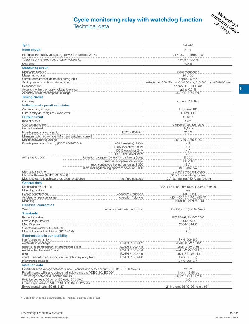
6
Measuring &
monitoring relays
CM Range
Low Voltage Products & Systems 6.203ABB Inc. • 888-385-1221 • www.abb.us/lowvoltage 1SXU000023C0202 Rev. A
Type CM-WDS
Input circuit A1-A2
Rated control supply voltage US - power consumption A1-A2 24 V DC - approx. 1 W
Tolerance of the rated control supply voltage US -30 % - +30 %Duty time 100 %Measuring circuit IMonitoring function cycle monitoringMeasuring voltage 24 V DCCurrent consumption at the measuring input approx. 5 mASetting range of cycle monitoring time selectable: 0.5-150 ms, 0.5-260 ms, 0.5-500 ms, 0.5-1000 msResponse time approx. 0.5-1000 msAccuracy within the supply voltage tolerance U m 0.5 %Accuracy within the temperature range U m 0.06 % / °CTiming circuitON-delay approx. 2.2-10 sIndication of operational statesControl supply voltage U: green LEDOutput relay de-energized / cycle error F: red LEDOutput circuit 11-12/14
Kind of output 1 c/oOperating principle 1) Closed-circuit principle Contact material AgCdoRated operational voltage Ue IEC/EN 60947-1 250 VMinimum switching voltage / Minimum switching currentMaximum switching voltage 250 V AC, 250 V DCRated operational current Ie (IEC/EN 60947-5-1) AC12 (resistive) 230 V 4 A
AC15 (inductive) 230 V 3 ADC12 (resistive) 24 V 4 A
DC13 (inductive) 24 V 2 AAC rating (UL 508) Utilization category (Control Circuit Rating Code) B 300
max. rated operational voltage 300 V ACmax. continuous thermal current at B 300 5 A
max. making/breaking apparent power at B 300 3600/360 VAMechanical lifetime 10 x 106 switching cyclesElectrical lifeteime (AC12, 230 V, 4 A) 0.1 x 10⁶ switching cyclesMax. fuse rating to achieve short-circuit protection n/c / n/o contacts 10 A fast-acting / 10 A fast-actingGeneral dataDimensions (W x H x D) 22.5 x 78 x 100 mm (0.89 x 3.07 x 3.94 in)Mounting position anyDegree of protection enclosure / terminals IP50 / IP20Ambient temperature range operation / storage -20...+60 °C / -40...+85 °CMounting DIN rail (IEC/EN 60715)Electrical connectionWire size fine-strand with wire end ferrule 2 x 2.5 mm2 (2 x 14 AWG)StandardsProduct standard IEC 255-6, EN 60255-6Low Voltage Directive 2006/95/ECEMC Directive 2004/108/ECOperational reliability (IEC 68-2-6) 4 gMechanical shock resistance (IEC 68-2-6) 6 gElectromagnetic compatibilityInterference immunity to EN 61000-6-2electrostatic discharge IEC/EN 61000-4-2 Level 3 (6 kV / 8 kV)radiated, radio-frequency, electromagnetic field IEC/EN 61000-4-3 Level 3 (10 V/m)electrical fast transient / burst IEC/EN 61000-4-4 Level 3 (2 kV / 5 kHz)surge IEC/EN 61000-4-5 Level 3 (2 kV L-L)conducted disturbances, induced by radio-frequency fields IEC/EN 61000-4-6 Level 3 (10 V)Interference emission EN 61000-6-4Isolation dataRated insulation voltage between supply-, control- and output circuit (VDE 0110, IEC 60947-1) 250 VRated impulse withstand between all isolated circuits (VDE 0110, IEC 664) 4 kV / 1.2-50 µsTest voltage between all isolated circuits 2.5 kV, 50 Hz, 1 minPollution degree (VDE 0110, IEC 664, IEC 255-5) 3/COvervoltage category (VDE 0110, IEC 664, IEC 255-5) IIIEnvironmental tests (IEC 68-2-30) 24 h cycle, 55 °C, 93 % rel. 96 h
1) Closed-circuit principle: Output relay de-energizes if a cycle error occurs
Cycle monitoring relay with watchdog functionTechnical data
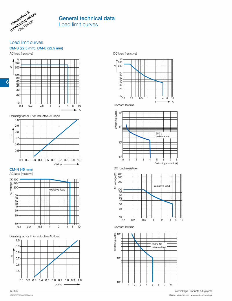
6
Measuring &
monitorin
g relays
CM Range
6.204 Low Voltage Products & Systems
1SXU000023C0202 Rev. A ABB Inc. • 888-385-1221 • www.abb.us/lowvoltage
DC load (resistive)AC load (resistive)
Contact lifetime
Derating factor F for inductive AC load
DC load (resistive)
AC load (resistive)CM-N (45 mm)
Load limit curvesCM-S (22.5 mm), CM-E (22.5 mm)
Contact lifetime
Derating factor F for inductive AC load
cos ϕ
F
0.5
0.1 0.2 0.3 0.4 0.5 0.6 0.7 0.8 0.9 1.0
0.6
0.7
0.8
0.9
1.0
300
200
1008060504030
20
101 2 4 6 10
I A
V
V
0.1 0.2 0.5
300
200
1008060504030
20
101 2 4 6 10
I A
V
V
0.1 0.2 0.5
cos ϕ
F
0.5
0.1 0.2 0.3 0.4 0.5 0.6 0.7 0.8 0.9 1.0
0.6
0.7
0.8
0.9
1.0
1 2 4 6 1010
20
30
40506080
100
200
300400
AC current [A]
resistive load
AC
vol
tage
[V]
0.1 0.2 0.5
4321
105
104
106
5 6 7 8Switching current [A]
Sw
itchi
ng c
ycle
s
250 V ACresistive load
Switching current [A]
250 Vresistive load
Sw
itchi
ng c
ycle
s
1 2 4 6 1010
20
30
40506080
100
200
300400
0.1 0.2 0.5AC current [A]
resistive load
AC
vol
tage
[V]
General technical dataLoad limit curves

6
Measuring &
monitoring relays
CM Range
Low Voltage Products & Systems 6.205ABB Inc. • 888-385-1221 • www.abb.us/lowvoltage 1SXU000023C0202 Rev. A
0.039
C512C513
x 5 ... 6 mm / PZ20,8 ... 1,2 Nm7 ... 10.3 lb·in
1 x 0,5 ... 4,0 mm22 x 0,5 ... 2,5 mm2
2 x 0,5 ... 1,5 mm21 x 0,5 ... 2,5 mm2
—
AWG 2 x 20 ... 14
10
10
10
a b c d
C512, C513 65 36 82,6 105,9
6
b
a
86
28,8
c d
201
6
45
7,2
2,86
5,19
73x5,811
73x5,831
CM-S
22.5 mm
CM-N
45 mm
CM-E
22.5 mm
Measuring and monitoring relays CM range old housing
Measuring and monitoring relays CM range new housing
C512/C513 45 mm
CM-TCS.xx 22.5 mm
CM-xxN 1SVR 750 xxx xxx, 1SVR 760 xxx xxx 45 mm
CM-xxS 1SVR 730 xxx xxx, 1SVR 740 xxx xxx 22.5 mm
Dimensions in mm
Temperature monitoring relays
4.31”109.5
102 4.02” 22.5
0.886”
78 3.07
”
5.50.216”
1003.94”
10.039”
114.5 4.51”
45.0 1.77”
85.6
3.
37”
104.8 4.13”
107.0 4.21”
113.4 44.65”
22.5 0.89”
85.6
33
.70”
103.7 40.83”
105.9 41.69”
General technical dataApproximate dimensions

6
Measuring &
monitorin
g relays
CM Range
6.206 Low Voltage Products & Systems
1SXU000023C0202 Rev. A ABB Inc. • 888-385-1221 • www.abb.us/lowvoltage
4,5 62,5
60
1011
,5
22,5
.177
”
2.46”
2.36”
.394
”
.886
”
.453
”
203A11 8
.315
”
.787”
22,5
68,5
73,5
.886”
2.70
”
.138”.275”
front-to-backsize 107
ADP.01
MAR.01
Sealable cover COV.01
Sealable cover COV.02
Accessories
Ordering details
Description For type Width in mm for devices Referencecode
Catalognumber
Pkg qty
Weight(1 pce)g (oz)
Adapter for screw mount-ing
CM-S 22.5 ADP.01 1SVR430029R0100 1 18.4 (0.65)
CM-N 45 ADP.02 1SVR440029R0100 1 36.7 (1.30)
Marker label
CM-S, CM-N without DIP switches MAR.01 1SVR366017R0100 10 0.19
(0.007)
CM-S, CM-N with DIPswitches MAR.02 1SVR430043R0000 10 0.13
(0.005)
CM-S, CM-Nin new housing
with DIPswitches MAR.12 1SVR730006R0000 10 0.152
(0.335
Sealable transparent cover
CM-S 22.5 COV.01 1SVR430005R0100 1 5.2 (0.18)
CM-N 45 COV.02 1SVR440005R0100 1 7.7 (0.27)
CM-S.S/P 22.5 COV.11 1SVR730005R0100 1 4.0 (0.129)
CM-N.S/P 45 COV.12 1SVR750005R0100 1 7 (0.247)
AccessoriesOrdering details
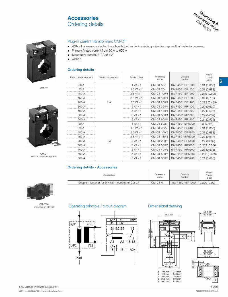
6
Measuring &
monitoring relays
CM Range
Low Voltage Products & Systems 6.207ABB Inc. • 888-385-1221 • www.abb.us/lowvoltage 1SXU000023C0202 Rev. A
CM-CT
k l
K-P1
x26
a
abcde
10,5 mm12,5 mm20,5 mm25,5 mm30,5 mm
0.41 inch0.49 inch0.81 inch1.00 inch1.20 inch
31 1
.22“
6,5
0.2
6“
75,5
2.9
7“78
,5 3
.09“
61 2.36“48 1.89“35 1.38“
a b c d e
bcde
40 1.57“
30 1.18“47 1.85“62 2.40“
60 2.36“
CM-CT with mounted accessories
Plug-in current transformers CM-CT Without primary conductor though with foot angle, insulating protective cap and bar fastening screws Primary / rated current from 50 A to 600 A Secondary current of 1 A or 5 A Class 1
Operating principle / circuit diagram Dimensional drawing
K/P1 k/S1
l/S2L/P2
load
CM-CT-A mounted on DIN rail
Ordering details
Rated primary current Secondary current Burden class Referencecode
Catalognumber
Weight(1 pce)g (oz)
50 A
1 A
1 VA / 1 CM-CT 50/1 1SVR450116R1000 0.31 (0.683)75 A 1.5 VA / 1 CM-CT 75/1 1SVR450116R1100 0.31 (0.683)
100 A 2.5 VA / 1 CM-CT 100/1 1SVR450116R1200 0.276 (0.608)150 A 2.5 VA / 1 CM-CT 150/1 1SVR450116R1300 0.32 (0.705)200 A 2.5 VA / 1 CM-CT 200/1 1SVR450116R1400 0.222 (0.489)300 A 5 VA / 1 CM-CT 300/1 1SVR450117R1100 0.29 (0.639)400 A 5 VA / 1 CM-CT 400/1 1SVR450117R1200 0.27 (0.595)500 A 5 VA / 1 CM-CT 500/1 1SVR450117R1300 0.29 (0.639)600 A 5 VA / 1 CM-CT 600/1 1SVR450117R1400 0.24 (0.529)50 A
5 A
1 VA / 1 CM-CT 50/5 1SVR450116R5000 0.3 (0.661)75 A 1.5 VA / 1 CM-CT 75/5 1SVR450116R5100 0.31 (0.683)
100 A 2.5 VA / 1 CM-CT 100/5 1SVR450116R5200 0.31 (0.683)150 A 2.5 VA / 1 CM-CT 150/5 1SVR450116R5300 0.28 (0.617)200 A 5 VA / 1 CM-CT 200/5 1SVR450116R5400 0.29 (0.639)300 A 5 VA / 1 CM-CT 300/5 1SVR450117R5100 0.252 (0.556)400 A 5 VA / 1 CM-CT 400/5 1SVR450117R5200 0.26 (0.573)500 A 5 VA / 1 CM-CT 500/5 1SVR450117R5300 0.208 (0.459)600 A 5 VA / 1 CM-CT 600/5 1SVR450117R5400 0.21 (0.463)
Ordering details - Accessories
Description Referencecode
Catalognumber
Weight(1 pce)g (oz)
Snap-on fastener for DIN rail mounting of CM-CT CM-CT A 1SVR450118R1000 0.009 (0.02)
AccessoriesOrdering details

6
Measuring &
monitorin
g relays
CM Range
6.208 Low Voltage Products & Systems
1SXU000023C0202 Rev. A ABB Inc. • 888-385-1221 • www.abb.us/lowvoltage
Notes

6
Interface relays
CR Range
Low Voltage Products & Systems 6.209ABB Inc. • 888-385-1221 • www.abb.us/lowvoltage 1SXU000023C0202 Rev. A
CR RangeInterface relays & optocouplers
Inte
rface
Rel
ays
& o
ptoc
oupl
ers
CR
Ran
ge

6
Interface re
lays
CR Range
6.210 Low Voltage Products & Systems
1SXU000023C0202 Rev. A ABB Inc. • 888-385-1221 • www.abb.us/lowvoltage
Notes

6
Interface relays
CR Range
Low Voltage Products & Systems 6.211ABB Inc. • 888-385-1221 • www.abb.us/lowvoltage 1SXU000023C0202 Rev. A
CR RangeInterface relays
Inte
rface
Rel
ays
CR
Ran
ge

6
Interface re
lays
CR Range
6.212 Low Voltage Products & Systems
1SXU000023C0202 Rev. A ABB Inc. • 888-385-1221 • www.abb.us/lowvoltage
Pluggable pcb relays CR-P 9 different coil voltages
– DC versions: 12 V, 24 V, 48 V, 110 V– AC versions: 24 V, 48 V, 110 V, 120 V, 230 V
Output contacts: – 1 c/o contact (16 A) or – 2 c/o contacts (8 A) optionally equipped with gold contacts
Logical or standard sockets
Cadmium-free contact material
Width on socket: 15,5 mm
Pluggable function modules– Reverse polarity protection/ Free wheeling diode– LED indication– RC elements– Overvoltage protection
Pluggable universal relays CR-U 10 different coil voltages
– DC versions: 12 V, 24 V, 48 V, 110 V, 125 V, 220 V– AC versions: 24 V, 48 V, 60 V, 110 V, 120 V, 230 V
Output contacts– 2 c/o contacts (10 A) or – 3 c/o contacts (10 A)
Integrated test button for manual actuation and locking of the output contacts (blue = DC, orange = AC) that can be removed if necessary
With or without integrated LED
Cadmium-free contact material
Width on socket: 38 mm
Pluggable function modules– Reverse polarity protection/ Free wheeling diode– LED indication– RC elements– Overvoltage protection– Multifunction time module
Pluggable miniature relays CR-M 12 different coil voltages
– DC versions: 12 V, 24 V, 48 V, 60 V, 110 V, 125 V, 220 V– AC versions: 24 V, 48 V, 60 V, 110 V, 120 V, 230 V
Output contacts– 2 c/o contacts (12 A) or– 3 c/o contacts (10 A) or – 4 c/o contacts (6 A) optionally equipped with gold contacts, LED and free wheeling diode
Integrated test button for manual actuation and locking of the output contacts (blue = DC, orange = AC) that can be removed if necessary
With or without integrated LED
Logical or standard sockets
Cadmium-free contact material
Width on socket: 27 mm
Pluggable function modules– Reverse polarity protection/ Free wheeling diode– LED indication– RC elements– Overvoltage protection
1 Socket
2 Pluggable function module
3 Interface relay
4 Holder
1 Socket
2 Pluggable function module
3 Interface relay
4 Holder
11
2 2
3 3
4
4
1 Socket
2 Pluggable function module
3 Interface relay
4 Holder
4 Marker label
1
2
3
4
4
Pluggable interface relaysBenefits and advantages

6
Interface relays
CR Range
Low Voltage Products & Systems 6.213ABB Inc. • 888-385-1221 • www.abb.us/lowvoltage 1SXU000023C0202 Rev. A
Approvals and marks
existing j pending Relays Sockets Modules
Approvals CR
-P
CR
-M
CR
-U
CR
-PLS
C
R-P
SS
CR
-PLC
CR
-M..L
.. C
R-M
..SS
CR
-M..S
F
CR
-U..S
C
R-U
..E
CR
-U..S
M
CR
-P/M
CR
-U
G UL 508 1)
cG CAN/CSA C22.2 No.14 2) 6) 7)
F CAN/CSA C22.2 No.14 3)
J VDE 4)
D GOST
P Lloyds Register 5)
E CCC
L RMRS
Marks
a CE
1) except 60 V DC and 125 V DC devices with gold contacts2) except devices with gold contacts3) except 60 V DC and 125 V DC devices4) except 125 V DC devices5) only devices with 4 c/o contacts6) except CR-P/M 42B, CR-P/M 42BV, CR-P/M 42C, CR-P/M 42CV, CR-P/M 52D, CR-P/M 62E, CR-P/M 62EV, CR-P/M 62D, CR-P/M 62DV7) except CR-U 41B, CR-U 41BV, CR-U 41C, CR-U 41CV, CR-U 51D, CR-U 61CV, CR-U 61E, CR-U 61EV, CR-U 61D, CR-U 61DV, CR-U 91C, CR-U T
Kinds of sockets
Standard sockets - Position of connecting terminals: Coil connection (A1-A2) on lower socket side, contact connections (n/o and n/c contacts) on the lower and upper socket side.
Logical sockets - Position of connecting terminals: Coil connection (A1-A2) on lower socket side, all contact connections (common contacts, n/o and n/c contacts) on upper socket side.
Details see connection diagrams
Kind of connecting terminals
Screw type Spring type Fork type
Pluggable interface relaysApprovals and marks

6
Interface re
lays
CR Range
6.214 Low Voltage Products & Systems
1SXU000023C0202 Rev. A ABB Inc. • 888-385-1221 • www.abb.us/lowvoltage
Description
Interface relays are widely used in various industrial applications:As an interface they link the electronic controlling, e.g. PLC (programmable logic controller), PC or field bus systems, to the sensor / actuator level. Here, they take on various functions: Switch-ing of AC or DC loads with different resistive, inductive and capacitive parts, switching voltages from a few mV up to 250 V, switching currents from a few mA up to 16 A, amplification of weak control signals, electrical isolation of control and load circuits, and signal multiplying. In contrast to electronic switching devices, interface relays don’t use additional internal protective circuits and thus are overload-proof against short-time variations like current or voltage peaks.
Ordering details - CR-P range
Rated control supply voltage
Outputs Contact ratingsReference
codeCatalognumber
Pkg
qty
Weight(1 pce)
kg (lb)
12 V DC
1 c/o (SPDT) 250 V, 16 A
CR-P012DC1 1SVR405600R4000
10 0.014 (0.031)
24 V DC CR-P024DC1 1SVR405600R1000
48 V DC CR-P048DC1 1SVR405600R6000
110 V DC CR-P110DC1 1SVR405600R8000
24 V AC CR-P024AC1 1SVR405600R000048 V AC CR-P048AC1 1SVR405600R5000110 V AC CR-P110AC1 1SVR405600R7000120 V AC CR-P120AC1 1SVR405600R2000230 V AC CR-P230AC1 1SVR405600R3000
12 V DC
2 c/o (SPDT) 250 V, 8 A
CR-P012DC2 1SVR405601R4000
10 0.014 (0.031)
24 V DC CR-P024DC2 1SVR405601R1000
48 V DC CR-P048DC2 1SVR405601R6000
110 V DC CR-P110DC2 1SVR405601R8000
24 V AC CR-P024AC2 1SVR405601R000048 V AC CR-P048AC2 1SVR405601R5000110 V AC CR-P110AC2 1SVR405601R7000120 V AC CR-P120AC2 1SVR405601R2000230 V AC CR-P230AC2 1SVR405601R3000
24 V DC
2 c/o gold contact 250 V, 8 A
CR-P024DC2 1SVR405606R1000
10 0.014 (0.031)
24 V AC CR-P024AC2G 1SVR405606R0000
110 V AC CR-P110AC2G 1SVR405606R7000
230 V AC CR-P230AC2G 1SVR405606R3000
Ordering details - Accessories
Version Connection terminalReference
codeCatalognumber
Pkg
qty
Weight(1 pce)
kg (lb)
Logical socket with protec-tive separation screw CR-PLS 1SVR405650R0000
10
0.045 (0.099)
Logical socket screw CR-PLSx 1SVR405650R0100 0.043 (0.095)
Logical socket spring CR-PLC 1SVR405650R0200 0.042 (0.093)
Standard socket screw CR-PSS 1SVR405650R1000 0.038 (0.084)
Plastic Holder for socket CR-PH 1SVR405659R000010
0.002 (0.004)
Jumper bar for sockets with screw connection CR-PJ 1SVR405658R5000 0.018 (0.040)
Marker CR-PM 1SVR405658R0000 10 0.0002 (0.0004)
CR-PLS
CR-P
CR-PJ
Pluggable interface relaysOrdering details

6
Interface relays
CR Range
Low Voltage Products & Systems 6.215ABB Inc. • 888-385-1221 • www.abb.us/lowvoltage 1SXU000023C0202 Rev. A
Description
Interface relays are widely used in various industrial applications:As an interface they link the electronic controlling, e.g. PLC (programmable logic controller), PC or field bus systems, to the sensor / actuator level. Here, they take on various functions: Switching of AC or DC loads with different resistive, inductive and capacitive parts, switching voltages from a few mV up to 250 V, switching currents from a few mA up to 16 A, amplification of weak control signals, electrical isolation of control and load circuits, and signal multiplying. In contrast to electronic switching devices, interface relays don’t use additional internal protective circuits and thus are overload-proof against short-time variations like current or voltage peaks.
Ordering details - CR-M range
Rated control supply voltage
Outputs Contact ratingsReference
codeCatalognumber
Pkg
qty
Weight(1 pce)
kg (lb)
12 V DC
2 c/o (SPDT)without LED 250 V, 12 A
CR-M012DC2 1SVR405611R4000
10 0.033 (0.073)
24 V DC CR-M024DC2 1SVR405611R100048 V DC CR-M048DC2 1SVR405611R600060 V DC CR-M060DC2 1SVR405611R4200110 V DC CR-M110DC2 1SVR405611R8000125 V DC CR-M125DC2 1SVR405611R8200220 V DC CR-M220DC2 1SVR405611R9000
24 V AC CR-M024AC2 1SVR405611R000048 V AC CR-M048AC2 1SVR405611R5000
110 V AC CR-M110AC2 1SVR405611R7000120 V AC CR-M120AC2 1SVR405611R2000230 V AC CR-M230AC2 1SVR405611R3000
12 V DC
3 c/o (SPDT)without LED 250 V, 10 A
CR-M012DC3 1SVR405612R4000
10 0.033 (0.073)
24 V DC CR-M024DC3 1SVR405612R100048 V DC CR-M048DC3 1SVR405612R600060 V DC CR-M060DC3 1SVR405612R4200110 V DC CR-M110DC3 1SVR405612R8000125 V DC CR-M125DC3 1SVR405612R8200220 V DC CR-M220DC3 1SVR405612R9000
24 V AC CR-M024AC3 1SVR405612R000048 V AC CR-M048AC3 1SVR405612R5000
CR-M060AC3 1SVR405612R5200
110 V AC CR-M110AC3 1SVR405612R7000120 V AC CR-M120AC3 1SVR405612R2000230 V AC CR-M230AC3 1SVR405612R3000
12 V DC
4 c/o (SPDT)without LED 250 V, 6 A
CR-M012DC4 1SVR405613R4000
10 0.033 (0.073)
24 V DC CR-M024DC4 1SVR405613R100048 V DC CR-M048DC4 1SVR405613R600060 V DC CR-M060DC4 1SVR405613R4200110 V DC CR-M110DC4 1SVR405613R8000125 V DC CR-M125DC4 1SVR405613R8200220 V DC CR-M220DC4 1SVR405613R9000
24 V AC CR-M024AC4 1SVR405613R000048 V AC CR-M048AC4 1SVR405613R5000
110 V AC CR-M110AC4 1SVR405613R7000120 V AC CR-M120AC4 1SVR405613R2000230 V AC CR-M230AC4 1SVR405613R3000
CR-M
Pluggable interface relaysOrdering details
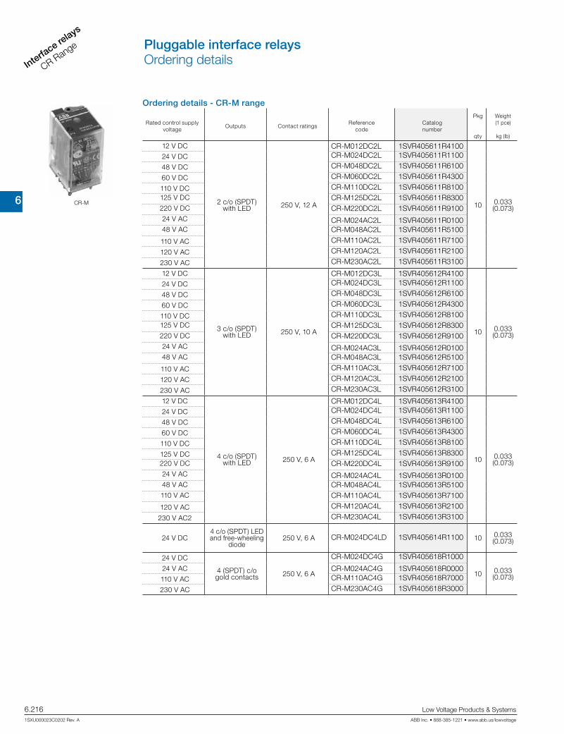
6
Interface re
lays
CR Range
6.216 Low Voltage Products & Systems
1SXU000023C0202 Rev. A ABB Inc. • 888-385-1221 • www.abb.us/lowvoltage
Ordering details - CR-M range
Rated control supply voltage
Outputs Contact ratingsReference
codeCatalognumber
Pkg
qty
Weight(1 pce)
kg (lb)
12 V DC
2 c/o (SPDT)with LED 250 V, 12 A
CR-M012DC2L 1SVR405611R4100
10 0.033 (0.073)
24 V DC CR-M024DC2L 1SVR405611R1100
48 V DC CR-M048DC2L 1SVR405611R6100
60 V DC CR-M060DC2L 1SVR405611R4300
110 V DC CR-M110DC2L 1SVR405611R8100125 V DC CR-M125DC2L 1SVR405611R8300220 V DC CR-M220DC2L 1SVR405611R910024 V AC CR-M024AC2L 1SVR405611R010048 V AC CR-M048AC2L 1SVR405611R5100
110 V AC CR-M110AC2L 1SVR405611R7100
120 V AC CR-M120AC2L 1SVR405611R2100
230 V AC CR-M230AC2L 1SVR405611R3100
12 V DC
3 c/o (SPDT)with LED 250 V, 10 A
CR-M012DC3L 1SVR405612R4100
10 0.033 (0.073)
24 V DC CR-M024DC3L 1SVR405612R1100
48 V DC CR-M048DC3L 1SVR405612R6100
60 V DC CR-M060DC3L 1SVR405612R4300
110 V DC CR-M110DC3L 1SVR405612R8100125 V DC CR-M125DC3L 1SVR405612R8300220 V DC CR-M220DC3L 1SVR405612R910024 V AC CR-M024AC3L 1SVR405612R010048 V AC CR-M048AC3L 1SVR405612R5100
110 V AC CR-M110AC3L 1SVR405612R7100
120 V AC CR-M120AC3L 1SVR405612R2100
230 V AC CR-M230AC3L 1SVR405612R3100
12 V DC
4 c/o (SPDT)with LED 250 V, 6 A
CR-M012DC4L 1SVR405613R4100
10 0.033 (0.073)
24 V DC CR-M024DC4L 1SVR405613R1100
48 V DC CR-M048DC4L 1SVR405613R6100
60 V DC CR-M060DC4L 1SVR405613R4300
110 V DC CR-M110DC4L 1SVR405613R8100
125 V DC CR-M125DC4L 1SVR405613R8300220 V DC CR-M220DC4L 1SVR405613R910024 V AC CR-M024AC4L 1SVR405613R010048 V AC CR-M048AC4L 1SVR405613R5100110 V AC CR-M110AC4L 1SVR405613R7100
120 V AC CR-M120AC4L 1SVR405613R2100
230 V AC2 CR-M230AC4L 1SVR405613R3100
24 V DC4 c/o (SPDT) LED and free-wheeling
diode250 V, 6 A CR-M024DC4LD 1SVR405614R1100 10 0.033
(0.073)
24 V DC
4 (SPDT) c/o gold contacts 250 V, 6 A
CR-M024DC4G 1SVR405618R1000
10 0.033 (0.073)
24 V AC CR-M024AC4G 1SVR405618R0000110 V AC CR-M110AC4G 1SVR405618R7000
230 V AC CR-M230AC4G 1SVR405618R3000
CR-M
Pluggable interface relaysOrdering details
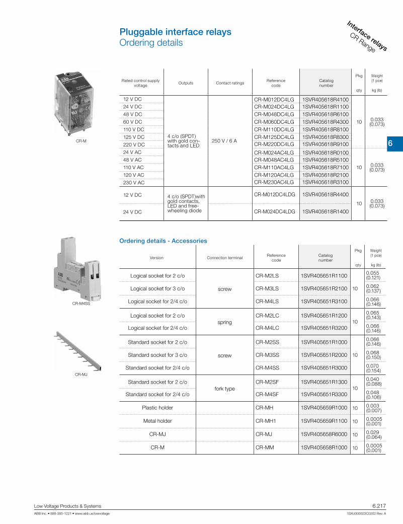
6
Interface relays
CR Range
Low Voltage Products & Systems 6.217ABB Inc. • 888-385-1221 • www.abb.us/lowvoltage 1SXU000023C0202 Rev. A
CR-M
Rated control supply voltage
Outputs Contact ratingsReference
codeCatalognumber
Pkg
qty
Weight(1 pce)
kg (lb)
12 V DC
4 c/o (SPDT) with gold con-tacts and LED
250 V / 6 A
CR-M012DC4LG 1SVR405618R4100
10 0.033 (0.073)
24 V DC CR-M024DC4LG 1SVR405618R110048 V DC CR-M048DC4LG 1SVR405618R610060 V DC CR-M060DC4LG 1SVR405618R4300110 V DC CR-M110DC4LG 1SVR405618R8100125 V DC CR-M125DC4LG 1SVR405618R8300220 V DC CR-M220DC4LG 1SVR405618R9100
24 V AC CR-M024AC4LG 1SVR405618R0100
10 0.033 (0.073)
48 V AC CR-M048AC4LG 1SVR405618R5100110 V AC CR-M110AC4LG 1SVR405618R7100120 V AC CR-M120AC4LG 1SVR405618R2100230 V AC CR-M230AC4LG 1SVR405618R3100
12 V DC 4 c/o (SPDT)with gold contacts, LED and free-wheeling diode
CR-M012DC4LDG 1SVR405618R4400
10 0.033 (0.073)
24 V DC CR-M024DC4LDG 1SVR405618R1400
Ordering details - Accessories
Version Connection terminalReference
codeCatalognumber
Pkg
qty
Weight(1 pce)
kg (lb)
Logical socket for 2 c/o
screw
CR-M2LS 1SVR405651R1100
10
0.055 (0.121)
Logical socket for 3 c/o CR-M3LS 1SVR405651R2100 0.062 (0.137)
Logical socket for 2/4 c/o CR-M4LS 1SVR405651R3100 0.066 (0.146)
Logical socket for 2 c/ospring
CR-M2LC 1SVR405651R120010
0.065 (0.143)
Logical socket for 2/4 c/o CR-M4LC 1SVR405651R3200 0.066 (0.146)
Standard socket for 2 c/o
screw
CR-M2SS 1SVR405651R1000
10
0.066 (0.146)
Standard socket for 3 c/o CR-M3SS 1SVR405651R2000 0.068 (0.150)
Standard socket for 2/4 c/o CR-M4SS 1SVR405651R3000 0.070 (0.154)
Standard socket for 2 c/ofork type
CR-M2SF 1SVR405651R130010
0.040 (0.088)
Standard socket for 2/4 c/o CR-M4SF 1SVR405651R3300 0.048 (0.106)
Plastic holder CR-MH 1SVR405659R1000 10 0.003 (0.007)
Metal holder CR-MH1 1SVR405659R1100 10 0.0005 (0.001)
CR-MJ CR-MJ 1SVR405658R6000 10 0.029 (0.064)
CR-M CR-MM 1SVR405658R1000 10 0.0005 (0.001)
CR-M4SS
CR-MJ
Pluggable interface relaysOrdering details

6
Interface re
lays
CR Range
6.218 Low Voltage Products & Systems
1SXU000023C0202 Rev. A ABB Inc. • 888-385-1221 • www.abb.us/lowvoltage
Ordering details - CR-P/M range
Rated control supply voltage
Description VersionReference
codeCatalognumber
Pkg
qty
Weight(1 pce)
kg (lb)
6-230 V DC
Diode - Reverse polar-ity protection/free wheeling diode
A1+, A2- CR-P/M 22 1SVR405651R0000 100.003 (0.007)
6-24 V DC Diode and LED - Reverse polarity protection/free wheeling diode
red, A1+, A2- CR-P/M 42 1SVR405652R0000
100.003 (0.007)
green, A1+, A2- CR-P/M 42V 1SVR405652R1000
24-60 V DCred, A1+, A2- CR-P/M 42B 1SVR405652R4000
green, A1+, A2- CR-P/M 42BV 1SVR405652R4100
110-230 V DCred, A1+, A2- CR-P/M 42C 1SVR405652R9000
green, A1+, A2- CR-P/M 42CV 1SVR405652R91006-24 V AC
Spark quenching
CR-P/M 52B 1SVR405653R0000
100.003 (0.007)
24-60 V AC CR-P/M 52D 1SVR405653R4000110-230 V AC CR-P/M 52C 1SVR405653R1000
6-24 V AC/DC
Diode and LED
red, for DC A1+, A2- CR-P/M 62 1SVR405654R0000
100.003 (0.007)
green, for DC A1+, A2- CR-P/M 62V 1SVR405654R1000
24-60 V AC/DCred, for DC A1+, A2- CR-P/M 62E 1SVR405654R4000
green, for DC A1+, A2- CR-P/M 62EV 1SVR405654R4100
110-230 V AC/DC
red, for DC A1+, A2- CR-P/M 92 1SVR405654R0100
green, for DC A1+, A2- CR-P/M 92V 1SVR405654R1100
6-24 V AC/DC
Varistor and LED Overvoltage protection
red, for DC A1+, A2- CR-P/M 62C 1SVR405655R0000
100.003 (0.007)
green, for DC A1+, A2- CR-P/M 62CV 1SVR405655R1000
24-60 V AC/DCred, for DC A1+, A2- CR-P/M 62D 1SVR405655R4000
green, for DC A1+, A2- CR-P/M 62DV 1SVR405655R4100
110-230 V AC/DC
red, for DC A1+, A2- CR-P/M 92C 1SVR405655R0100
green, for DC A1+, A2- CR-P/M 92CV 1SVR405655R1100
24 V ACOvervoltage protection
CR-P/M 72 1SVR405656R0000
100.002 (0.004)
115 V AC CR-P/M 72A 1SVR405656R1000230 V AC CR-P/M 82 1SVR405656R2000
Connection diagrams
CR-P/M 22 CR-P/M 42, CR-P/M 42B, CR-P/M 42C, CR-P/M 42V, CR-P/M 42BV, CR-P/M 42CV
CR-P/M 52B, CR-P/M 52C CR-P/M 52D,
CR-P/M 62, CR-P/M 62E, CR-P/M 92, CR-P/M 62V, CR-P/M 62EV, CR-P/M 92V
CR-P/M 62C, CR-P/M 62D, CR-P/M 92C, CR-P/M 62CV, CR-P/M 62DV CR-P/M 92CV
CR-P/M 72, CR-P/M 82 CR-P/M 72A,
CR-P/M ...
Pluggable interface relaysOrdering details

6
Interface relays
CR Range
Low Voltage Products & Systems 6.219ABB Inc. • 888-385-1221 • www.abb.us/lowvoltage 1SXU000023C0202 Rev. A
Description
Interface relays are widely used in various industrial applications:As an interface they link the electronic controlling, e.g. PLC (programmable logic controller), PC or field bus systems, to the sensor / actuator level. Here, they take on various functions: Switching of AC or DC loads with different resistive, inductive and capacitive parts, switching voltages from a few mV up to 250 V, switching currents from a few mA up to 16 A, amplification of weak control signals, electrical isolation of control and load circuits, and signal multiplying. In contrast to electronic switching devices, interface relays don’t use additional internal protective circuits and thus are overload-proof against short-time variations like current or voltage peaks.
Ordering details - CR-U range
Rated control supply voltage
Outputs Contact ratingsReference
codeCatalognumber
Pkg
qty
Weight(1 pce)kg (lb)
12 V DC
2 c/o without LED 250 V, 10 A
CR-U012DC2 1SVR405621R4000
10 0.083 (0.183)
24 V DC CR-U024DC2 1SVR405621R100048 V DC CR-U048DC2 1SVR405621R6000110 V DC CR-U110DC2 1SVR405621R8000220 V DC CR-U220DC2 1SVR405621R900024 V AC CR-U024AC2 1SVR405621R000048 V AC CR-U048AC2 1SVR405621R5000110 V AC CR-U110AC2 1SVR405621R7000120 V AC CR-U120AC2 1SVR405621R2000230 V AC CR-U230AC2 1SVR405621R300012 V DC
3 c/o without LED 250 V, 10 A
CR-U012DC3 1SVR405622R4000
10 0.083 (0.183)
24 V DC CR-U024DC3 1SVR405622R100048 V DC CR-U048DC3 1SVR405622R6000110 V DC CR-U110DC3 1SVR405622R8000125 V DC CR-U125DC3 1SVR405622R8200220 V DC CR-U220DC3 1SVR405622R900024 V AC CR-U024AC3 1SVR405622R000048 V AC CR-U048AC3 1SVR405622R500060 V AC CR-U060AC3 1SVR405622R5200110 V AC CR-U110AC3 1SVR405622R7000120 V AC CR-U120AC3 1SVR405622R2000230 V AC CR-U230AC3 1SVR405622R300012 V AC
2 c/o with LED 250 V, 10 A
CR-U012DC2L 1SVR405621R4100
10 0.083 (0.183)
24 V DC CR-U024DC2L 1SVR405621R110048 V DC CR-U048DC2L 1SVR405621R6100110 V DC CR-U110DC2L 1SVR405621R8100220 V DC CR-U220DC2L 1SVR405621R910024 V AC CR-U024AC2L 1SVR405621R010048 V AC CR-U048AC2L 1SVR405621R5100110 V AC CR-U110AC2L 1SVR405621R7100120 V AC CR-U120AC2L 1SVR405621R2100230 V AC CR-U230AC2L 1SVR405621R310012 V DC
3 c/o with LED 250 V, 10 A
CR-U012DC3L 1SVR405622R4100
10 0.083 (0.183)
24 V DC CR-U024DC3L 1SVR405622R110048 V DC CR-U048DC3L 1SVR405622R6100110 V DC CR-U110DC3L 1SVR405622R8100220 V DC CR-U220DC3L 1SVR405622R910024 V AC CR-U024AC3L 1SVR405622R010048 V AC CR-U048AC3L 1SVR405622R5100110 V AC CR-U110AC3L 1SVR405622R7100120 V AC CR-U120AC3L 1SVR405622R2100230 V AC CR-U230AC3L 1SVR405622R3100
CR-U
CR-U2S
Ordering details - Accessories
VersionReference
codeCatalognumber
Pkg
qty
Weight(1 pce)kg (lb)
Socket for 2 c/o and module CR-U2S 1SVR405670R0000
10
Socket for 3 c/o and module CR-U3S 1SVR405660R0000
Socket for 3 c/o CR-U3E 1SVR405660R0100
Socket small for 2 c/o CR-U2SM 1SVR405670R1100
Socket small for 3 c/o CR-U3SM 1SVR405660R1100
Holder for CR-U socket CR-UH 1SVR405669R0000
Pluggable interface relaysOrdering details

6
Interface re
lays
CR Range
6.220 Low Voltage Products & Systems
1SXU000023C0202 Rev. A ABB Inc. • 888-385-1221 • www.abb.us/lowvoltage
Ordering details - CR-U range
Rated control supply voltage
Description VersionReference
codeCatalognumber
Pkg
qty
Weight(1 pce)
kg (lb)
6-230 V DC
Diode - Reverse polar-
ity protection/free wheeling diode
A1+, A2- CR-U 21 1SVR405661R0000 100.007 (0.015)
6-24 V DC
Diode and LED - Reverse polar-
ity protection/free wheeling diode
red, A1+, A2- CR-U 41 1SVR405662R0000
100.007 (0.015)
green, A1+, A2- CR-U 41V 1SVR405662R1000
24-60 V DCred, A1+, A2- CR-U 41B 1SVR405662R4000
green, A1+, A2- CR-U 41BV 1SVR405662R4100
110-230 V DCred, A1+, A2- CR-U 41C 1SVR405662R9000
green, A1+, A2- CR-U 41CV 1SVR405662R9100
6-24 V AC
Spark quenching
CR-U 51B 1SVR405663R0000
100.007 (0.015)
24-60 V AC CR-U 51D 1SVR405663R4000
110-230 V AC CR-U 51C 1SVR405663R1000
6-24 V AC/DC
Diode and LED
red, for DC A1+, A2- CR-U 61 1SVR405664R0000
100.007 (0.015)
green, for DC A1+, A2- CR-U 61V 1SVR405664R1000
24-60 V AC/DCred, for DC A1+, A2- CR-U 61E 1SVR405664R4000
green, for DC A1+, A2- CR-U 61EV 1SVR405664R4100
110-230 V AC/DC
red, for DC A1+, A2- CR-U 91 1SVR405664R0100
green, for DC A1+, A2- CR-U 91V 1SVR405664R1100
6-24 V AC/DC
Varistor and LED Overvoltage pro-
tection
red, for DC A1+, A2- CR-U 61C 1SVR405665R0000
100.007 (0.015)
green, for DC A1+, A2- CR-U 61CV 1SVR405665R1000
24-60 V AC/DCred, for DC A1+, A2- CR-U 61D 1SVR405665R4000
green, for DC A1+, A2- CR-U 61DV 1SVR405665R4100
110-230 V AC/DC
red, for DC A1+, A2- CR-U 91C 1SVR405665R0100
green, for DC A1+, A2- CR-U 91CV 1SVR405665R1100
24 V ACOvervoltage pro-
tection
CR-U 71 1SVR405666R0000
100.007 (0.015)
115 V AC CR-U 71A 1SVR405666R1000
230 V AC CR-U 81 1SVR405666R2000
24-240 V AC/DC
Multifunction time module
pluggable onto CR-U2S and CR-U3S
CR-U T 1SVR405667R0000 100.014 (0.031)
CR-U...
CR-U T
Connection diagrams
CR-U 21 CR-U 41, CR-U 41B, CR-U 41C, CR-U 41V, CR-U 41BV, CR-U 41CV
CR-U 51B, CR-U 51C CR-U 51D,
CR-U 61, CR-U 61E, CR-U 91, CR-U 61V, CR-U 61EV, CR-U 91V
CR-U 61C, CR-U 61D, CR-U 91C, CR-U 61CV, CR-U 61DV CR-U 91CV
CR-U 71, CR-U 81 CR-U 71A,
All CR-U modules can be plugged onto sockets CR-U2S and CR-U3S.
Pluggable interface relaysOrdering details

6
Interface relays
CR Range
Low Voltage Products & Systems 6.221ABB Inc. • 888-385-1221 • www.abb.us/lowvoltage 1SXU000023C0202 Rev. A
Input circuit - coil data
Rated control supply
voltage US
Rated frequency
Make voltage
(at 20 °C)
Maximum voltage
(at 55 °C)
Break voltage
Rated power
Coil resistance (at 20 °C)
Tolerance of coil
resistance
DC coils 12 V DC - 8.4 V DC 30.6 V DC M 0.1 US 0.4-0.48 W 360 w 10% 24 V DC - 16.8 V DC 61.2 V DC M 0.1 US 0.4-0.48 W 1440 w 10% 48 V DC - 33.6 V DC 122.4 V DC M 0.1 US 0.4-0.48 W 5700 w 10%110 V DC - 77 V DC 280 V DC M 0.1 US 0.4-0.48 W 25200 w 10%
AC coils 24 V AC 50 / 60 Hz 19.2 V AC 28.8 V AC M 0.15 US 0.75 VA 400 w 10% 48 V AC 50 / 60 Hz 38.4 V AC 57.6 V AC M 0.15 US 0.75 VA 1550 w 10%110 V AC 50 / 60 Hz 88 V AC 132 V AC M 0.15 US 0.75 VA 8900 w 10%120 V AC 50 / 60 Hz 96 V AC 144 V AC M 0.15 US 0.75 VA 10200 w 10%230 V AC 50 / 60 Hz 184 V AC 276 V AC M 0.15 US 0.75 VA 38500 w 10%
CR-P range
CR-M range
Rated control supply
voltage US
Rated frequency
Make voltage
(at 20 °C)
Maximum voltage
(at 55 °C)
Break voltage
Rated power
Coil resistance (at 20 °C)
Tolerance of coil
resistance
DC coils 12 V DC - 9.6 V DC 13.2 V DC M 0.1 US 0.9 W 160 w 10% 24 V DC - 19.2 DC 26.4 V DC M 0.1 US 0.9 W 640 w 10% 48 V DC - 38.4 V DC 52.8 V DC M 0.1 US 0.9 W 2600 q w 10%
60 V DC - 48.0 V DC 66.0 V DC M 0.1 US 0.9 W 4000 w 10%110 V DC - 88 V DC 121 V DC M 0.1 US 0.9 W 13600 w 10%125 V DC - 100 V DC 137,5 V DC M 0.1 US 0.9 W 16000 w 10%
220 V DC - 176 V DC 242 V DC M 0.1 US 0.9 W 54000 w 10%
AC coils 24 V AC 50 / 60 Hz 19.2 V AC 26.4 V AC M 0.2 US 1.6 VA 158 w 10% 48 V AC 50 / 60 Hz 38.4 V AC 52.8 V AC M 0.2 US 1.6 VA 640 w 10%
60 V AC 50 / 60 Hz 48.0 V AC 66.0 V AC M 0.2 US 1.6 VA 930 w 10%110 V AC 50 / 60 Hz 88 V AC 121 V AC M 0.2 US 1.6 VA 3450 w 10%120 V AC 50 / 60 Hz 96 V AC 132 V AC M 0.2 US 1.6 VA 3770 w 10%230 V AC 50 / 60 Hz 184 V AC 253 V AC M 0.2 US 1.6 VA 16100 w 10%
Rated control supply
voltage US
Rated frequency
Make voltage
(at 20 °C)
Maximum voltage
(at 55 °C)
Break voltage
Rated power
Coil resistance (at 20 °C)
Tolerance of coil
resistance
DC coils 12 V DC - 9.6 V DC 13.2 V DC M 0.1 Us 1.5 W 110 w 10 %24 V DC - 19.2 V DC 26.4 V DC M 0.1 Us 1.5 W 430 w 10 %48 V DC - 38.4 V DC 52.8 V DC M 0.1 Us 1.5 W 1750 w 10 %
110 V DC - 88.0 V DC 121.0 V DC M 0.1 Us 1.5 W 9200 q w 10 %125 V DC - 96.0 V DC 132.0 V DC M 0.1 Us 1.5 W 11000 w 10 %220 V DC - 176.0 V DC 242.0 V DC M 0.1 Us 1.5 W 37000 w 10 %
AC coils 24 V AC 50 / 60 Hz 19.2 V AC 26.4 V AC M 0.15 Us 2.8 VA (50 Hz)2.5 VA (60 Hz)
75 w 10 %
48 V AC 50 / 60 Hz 38.4 V AC 52.8 V AC M 0.15 Us 2.8 VA (50 Hz)2.5 VA (60 Hz)
305 w 10 %
60 V AC 50 / 60 Hz 48.0 V AC 66.0 V AC M 0.15 Us 2.8 VA (50 Hz)2.5 VA (60 Hz)
475 w 10 %
110 V AC 50 / 60 Hz 88.0 V AC 121.0 V AC M 0.15 Us 2.8 VA (50 Hz)2.5 VA (60 Hz)
1700 w 10 %
120 V AC 50 / 60 Hz 96.0 V AC 132.0 V AC M 0.15 Us 2.8 VA (50 Hz)2.5 VA (60 Hz)
1910 w 10 %
230 V AC 50 / 60 Hz 184.0 V AC 253.0 V AC M 0.15 Us 2.8 VA (50 Hz)2.5 VA (60 Hz)
7080 w 10 %
CR-U range
Pluggable interface relaysTechnical data

6
Interface re
lays
CR Range
6.222 Low Voltage Products & Systems
1SXU000023C0202 Rev. A ABB Inc. • 888-385-1221 • www.abb.us/lowvoltage
Type CR-P...1 CR-P...2 CR-M...2 CR-M...3 CR-M...4 CR-U...2 CR-U...3
Output circuit(s) 11-12/14 11-12/14 21-22/24
11-12/1421-22/24
11-12/1421-22/2431-32/34
11-12/1421-22/2431-32/3441-42/44
11-12/1431-32/34
11-12/1421-22/2431-32/34
Kind of output Relay, 1 c/o Relay, 2 c/o Relay, 2 c/o Relay, 3 c/o Relay, 4 c/o Relay, 2 c/o Relay, 3 c/o
Contact material AgNi AgNi AgNi/Au 5 µm AgNi AgNi AgNi
AgNi/Au 5 µm AgNi
Rated operational voltage Ue (VDE 0110, IEC 60947-1) 250 V
Minimum switching voltage 5 V
Maximum switching voltage DC 300 V DC 250 V DC
AC 400 V AC 250 V AC
Minimum switching current 5 mA (AgNi), 2 mA (AgNi/Au)
Rated free air thermal current Ith 16 A 8 A 12 A 10 A 6 A 10 A
Rated operationalcurrent (IEC 60947-5-1)
AC12 (resistive) 230 V 16 A 8 A 12 A 10 A 6 A 10 A
AC15 (inductive) 230 V 1.5 A 1 A 1.5 A 1.5 A 1 A 1.5 A
DC12 (resistive) 24 V 16 A 8 A 12 A 10 A 6 A 10 A
DC13 (inductive) 24 V 2 A 2 A 8 A 8 A 6 A 2 A
AC rating (UL 508)
Utilization category (Control Circuit Rating Code)
- - - B 300
max. rated operational voltage - - - 300 V AC
max. continuous thermal current at B 300
- - - 5 A
max. making / breaking apparent power at B 300
- - - 3600/360 VA
Utilization category General Purpose (single phase)
- - 10 A, 250 V AC
10 A, 250 V AC
Utilization category (Resistive) 16 A, 250
V AC 8 A, 250 V AC
10 A, 250 V AC
12 A, 150 V AC
6 A, 250 V AC 10 A, 150
V AC
6 A, 250 V AC 10 A, 150
V AC
10 A, 250 V AC -
Minmum switching power 0.3 W (AgNi), 0.1 W (AgNi/Au) 0.3 W
Maximum switching power AC-1 4000 VA 2000 VA 3000 VA 2500 VA 1500 VA 2500 VA
Contact resistance 100 m 100 m
Maximum switching capacity rated load AC-1 600 switching cycles/h 1200 switching cycles/h
without load 72000 switching cycles/h 18000 switching cycles/h 12000 switching cycles/h
Mechanical lifetime > 3 x 10⁷ switching cycles > 2 x 10⁷ switching cycles
Electrical lifetime AC1 (resistive) > 105 switching cycles > 105 switching cycles > 105 switching cycles(16 A, 250 V) (8 A, 250 V) (12 A, 250 V) (10 A, 250 V) (6 A, 250 V) (10 A, 250 V)
cos ϕ see reduction factor F
Response time typ. 7 ms typ. 13 ms (DC),10 ms (AC) typ. 18 ms (DC), 12 ms (AC)
Release time typ. 3 ms typ. 3 ms (DC), 8 ms (AC) typ. 7 ms (DC), 10 ms (AC)
Isolation dataRated insulation voltage 400 V AC 250 V AC
Insulation class C250 / B400 C250 / B250 C250
Rated impulsewithstand voltage Uimp
between coil and contacts 5 kV AC 2.5 kV AC
between open contacts 1 kV AC 1.5 kV AC
between c/o contacts 2.5 kV AC 2.5 kV AC 2 kV AC 2 kV AC
Clearance between coil and contacts 10 mm 2.5 mm 1.6 mm 3 mm
Creepage distance between coil and contacts 10 mm 4 mm 3.2 mm 4.2 mm
Overvoltage category III III II III
Pollution degree 3 3 2 3
General dataDimensions (W x H x D) when mounted 12.7 x 29 x 15.7 mm 21.2 x 27.5 x 35.6 mm 35 x 35 x 54.4 mm
Weight 14 g (0.031 lb) 35 g (0.077 lb) 83 g (0.18 lb)
Mounting on socket (see accessories)
Mounting position any
Degree of protection IP 67 IP 40
Electrical connectionConnection by socket
Pluggable interface relaysTechnical data
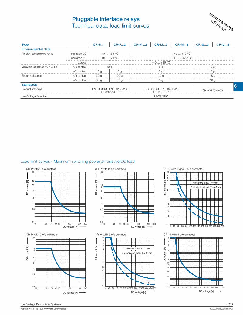
6
Interface relays
CR Range
Low Voltage Products & Systems 6.223ABB Inc. • 888-385-1221 • www.abb.us/lowvoltage 1SXU000023C0202 Rev. A
Type CR-P...1 CR-P...2 CR-M...2 CR-M...3 CR-M...4 CR-U...2 CR-U...3
Environmental dataAmbient temperature range operation DC -40 ... +85 °C -40 ... +70 °C
operation AC -40 ... +70 °C -40 ... +55 °C
storage -40 ... +85 °C
Vibration resistance 10-150 Hz n/o contact 10 g 5 g 5 g
n/c contact 10 g 5 g 5 g 5 g
Shock resistance n/o contact 30 g 20 g 10 g 10 g
n/c contact 30 g 20 g 5 g 10 g
StandardsProduct standard EN 61810-1, EN 60255-23
IEC 60664-1EN 60810-1, EN 60255-23
IEC 61810-7 EN 60255-1-00
Low Voltage Directive 73/23/EEC
Load limit curves - Maximum switching power at resistive DC load
CR-P with 1 c/o contact CR-P with 2 c/o contacts CR-U with 2 and 3 c/o contacts
CR-M with 2 c/o contacts CR-M with 3 c/o contacts CR-M with 4 c/o contacts
DC
cur
rent
[A]
DC voltage [V]
DC
cur
rent
[A]
DC voltage [V]
1 = resistive load, T = 0 ms
2 = inductive load, T = 40 ms
DC voltage [V]
DC
cur
rent
[A]
DC
cur
rent
[A]
DC voltage [V]
1 = resistive load, T = 0 ms
2 = inductive load, T = 40 ms
DC voltage [V]
DC
cur
rent
[A]
DC voltage [V]
DC
cur
rent
[A]
Pluggable interface relaysTechnical data, load limit curves

6
Interface re
lays
CR Range
6.224 Low Voltage Products & Systems
1SXU000023C0202 Rev. A ABB Inc. • 888-385-1221 • www.abb.us/lowvoltage
Load limit curves - Electrical lifetime at resistive AC load
CR-P with 1 c/o contact CR-P with 2 c/o contacts CR-U with 2 and 3 c/o contacts
CR-M with 2 c/o contacts CR-M with 3 c/o contacts CR-M with 4 c/o contacts
Sw
itchi
ng c
ycle
s
Switching power [kVA]
Sw
itchi
ng c
ycle
s
Switching power [kVA]
Sw
itchi
ng c
ycle
s
Switching power [kVA]
Sw
itchi
ng c
ycle
s
Switching power [kVA]
Sw
itchi
ng c
ycle
s
Switching power [kVA]
Sw
itchi
ng c
ycle
s
Switching power [kVA]
Reduction factor F at inductive AC load
Red
uctio
n fa
ctor
Power factor
Red
uctio
n fa
ctor
Power factor Power factor
Red
uctio
n fa
ctor
CR-P CR-M CR-U
Pluggable interface relaysLoad limit curves

6
Interface relays
CR Range
Low Voltage Products & Systems 6.225ABB Inc. • 888-385-1221 • www.abb.us/lowvoltage 1SXU000023C0202 Rev. A
Connection diagrams
Dimensional drawings Dimensions in mm
CR-M with 2 c/o contacts
CR-P with 1 c/o contact CR-M with 2 c/o contacts CR-M with 3 c/o contacts CR-U with 2 c/o contacts
CR-P with 2 c/o contacts CR-M with 4 c/o contacts CR-U with 3 c/o contacts
CR-U with 2 c/o contacts
CR-P CR-M with 3 c/o contacts CR-U with 3 c/o contacts
Pluggable interface relaysConnection diagrams

6
Interface re
lays
CR Range
6.226 Low Voltage Products & Systems
1SXU000023C0202 Rev. A ABB Inc. • 888-385-1221 • www.abb.us/lowvoltage
Dimensional drawings Dimensions in mm
Sockets for screw connection
CR-PLS
CR-PLSx
CR-PSS
CR-U2S - CR-U3S
CR-M2SS - CR-M3SS - CR-M4SS
Holder
Pluggable func-tion module
Relay
20.3
2
5.08
5.08
15.5
7.62
29.4
3.2
78.5
24
50
62
61
42.5
CR-M2LS - CR-M3LS - CR-M4LS
CR-U3E
9 - M3
12 - M3
37,3 38,1
29,8 29,8
4
75,3
75,3
35,4
CR-U2S CR-U3S
62
62
51,2
2915,87,5
76
20
10
Marker
Relay
Holder
Pluggable function module
42.8
15,8
24
76
10
20
Marker
Holder
Relay
Pluggablefunction module
27,2
27,2 27,2
75,2
35,4
24
42,6
Marker
Relay
Holder
Pluggable function module
29,1
2442,6
75
60,827,2
27,2 27,2
75 35,4
Marker
Relay
Holder
Pluggablefunction module
CR-M2LS CR-M3LS CR-M4LS
Pluggable interface relaysApproximate dimensions

6
Interface relays
CR Range
Low Voltage Products & Systems 6.227ABB Inc. • 888-385-1221 • www.abb.us/lowvoltage 1SXU000023C0202 Rev. A
CR-U2SM
CR-U3SM
11 - M3
27,8
38,126
61,8
4
35,4
27,8
38,1
CR-U2SM CR-U3SM
8 - M3
61,8
Dimensional drawings Dimensions in mm
Jumper
31
27 26
79,5
42,5
33,2
24
12,4
12,4
15
95
5,5
CR-PLC CR-M2LC , CR-M4LC
CR-PJ
CR-MJ
7,62
97,5
25,9
20,3
2
5,08
5,08
24,4
16,3
33,8
43,5
34,4
246.8
19,5
10
R1
9 x 27.2 (=244,8)
27.2 ±0.2
6±0,
2
2±0,2
1,510
10
R1
2±0,2
15,5±0,2
9x15 (=139,5)
141,5+16±0,
2
Pluggable interface relaysApproximate dimensions
Sockets for spring connection

6
Interface re
lays
CR Range
6.228 Low Voltage Products & Systems
1SXU000023C0202 Rev. A ABB Inc. • 888-385-1221 • www.abb.us/lowvoltage
Notes

6
Interface relays
CR Range
Low Voltage Products & Systems 6.229ABB Inc. • 888-385-1221 • www.abb.us/lowvoltage 1SXU000023C0202 Rev. A
Interface relays
R600 & R500 Range
Interface relaysR600, R500
Inte
rface
rela
ysR
600
& R
500

6
Interface re
lays
CR Range
6.230 Low Voltage Products & Systems
1SXU000023C0202 Rev. A ABB Inc. • 888-385-1221 • www.abb.us/lowvoltage
Interface re
lays
R600 & R500 Range
In today’s automation systems, PLCs are the core of industry. They link sensors and actuators to the process, which are connected to the PLC via con-ventional wires.
However these PLCs are not completely isolated from the industrial environment, hence voltage spikes and transient currents can affect their operating functions. And additionally, their application range is often limited to 24 VDC / 100 mA.So, with the aim to adapt application voltage and/or current and provide as well the appropriate galvanic isolation to the PLC, it is recommended to install the correct interface to provide both voltage-current level adaptation and isolation protection.This interfacing is possible thanks to ABB’s relays and optocouplers ranges, which offer wide adaptation in both voltage (from 5 to 400 V) and current (from 10-7 to 16 A) as well as high isolation between input and output from 2 to 4 KV.
R500 series
Standard range with pluggable functions
Spacing : 5.08 mm (the smallest in the market) Wire size : 2.5 mm² (4 mm² solid) Contact type : 1 SPDT from 10 mA to 6 A / 250 V Transistor : 30 mA to 100 mA
MOS : 1 A to 2 A Triac : 1 A
R600 series
Standard range in screw clamp or spring clamp versions
Spacing : 6 mm Wire size : 2.5 mm² (4 mm² solid wire) Contact type : 1 NO, 1 NC, 1 SPDT, 1 DPDT from
1 mA to 8 A / 250 V Transistor : 100 mA
MOS : 1 A to 5 A Triac : 1 A to 2 A
Interface relays, R600, R500Benefits and advantages

6
Interface relays
CR Range
Low Voltage Products & Systems 6.231ABB Inc. • 888-385-1221 • www.abb.us/lowvoltage 1SXU000023C0202 Rev. A
Interface relays
R600 & R500 Range
SERIES CODE NB OF RELAYS CONTACT TYPE NB OF CONTACTS PARTICULARITIES PER RELAY R 600 R B
R 600 R B R
R 500 D 2,5/5 R
0 None 1 1 1 A 2 2 2 B 3 C N P R V I
Description of contact types
0 1 Normally Closed 1 NC
1 1 Normally Open 1 NO
2 1 Change Over or Single Pole Double Through
3 1 Normally Closed + 1 Normally Open 1 NC + 1 NO
Features
None Input voltage DC A Input voltage AC/DC B Input voltage AC C 2 wire sensor compatibility
N Commons of coils connected to negative
P Commons of coils connected to positive
R RC circuit protection : - Input protection against leakage current
- Increases relay contacts life
V Relay protection against overvoltage peaks
I Switch to force the coil for maintenance and/or installation purposes
Color coding for relays
Color Current level Switching Switching Switching in contacts current voltage load power
green Very low level 10-7 to 5 A 10-3 to 250 V 10-10 to 2000 VA 10-10 to 200 W
grey Low level 1 mA to 8 A 5 to 250 V 0,05 to 1500 VA
0,05 to 192 W
blue High level 10 mA to 16 A 12 to 380 V 0,6 to 4000 VA
0,6 to 240 W
A1
A3
Autooff
Manu
Interface relays, R600, R500Type designators

6
Interface re
lays
CR Range
6.232 Low Voltage Products & Systems
1SXU000023C0202 Rev. A ABB Inc. • 888-385-1221 • www.abb.us/lowvoltage
Interface re
lays
R600 & R500 RangeInterface relays, R600Selection
Ref
eren
ce c
ode
RB
121
-5V
DC
RB
121
-5V
DC
RB
R 1
21-5
VD
C
RB
R 1
21-5
VD
C
RB
121
-12V
DC
RB
121
-12V
DC
RB
R 1
21-1
2VD
C
RB
R 1
21-1
2VD
C
RB
101
AR
-24V
AC
/DC
RB
R 1
01A
R-2
4VA
C/D
C
RB
111
A-2
4VA
C/D
C
RB
111
AI-
24VA
C/D
C
RB
111
AR
-24V
AC
/DC
RB
R 1
11A
-24V
AC
/DC
RB
R 1
11A
I-24
VAC
/DC
RB
R 1
11A
R-2
4VA
C/D
C
RB
121
-24V
DC
RB
121
-24V
DC
RB
121
A-2
4VA
C/D
C
RB
121
A-2
4VA
C/D
C
RB
121
AI-
24VA
C/D
C
RB
121
AI-
24VA
C/D
C
RB
121
AI-
24VA
C/D
C
RB
121
AI-
24VA
C/D
C
RB
R 1
21-2
4VD
C
RB
R 1
21-2
4VD
C
RB
R 1
21A
-24V
AC
/DC
RB
R 1
21A
-24V
AC
/DC
RB
R 1
21A
I-24
VAC
/DC
RB
R 1
21A
I-24
VAC
/DC
RB
R 1
21A
I-24
VAC
/DC
RB
R 1
21A
I-24
VAC
/DC
RB
122
A-2
4VA
C/D
C
RB
R 1
22A
-24V
AC
/DC
RB
111
A-4
8-60
VAC
/DC
RB
R 1
11A
-48-
60VA
C/D
C
RB
121
A-4
8-60
VAC
/DC
RB
121
A-4
8-60
VAC
/DC
RB
R 1
21A
-48-
60VA
C/D
C
RB
R 1
21A
-48-
60VA
C/D
C
RB
122
A-4
8-60
VAC
/DC
RB
R 1
22A
-48-
60VA
C/D
C
RB
121
A-1
15VA
C/D
C
RB
121
A-1
15VA
C/D
C
RB
121
AR
-115
VAC
/DC
RB
R 1
21A
-115
VAC
/DC
RB
R 1
21A
-115
VAC
/DC
RB
R 1
21A
R-1
15VA
C/D
C
RB
122
A-1
15VA
C/D
C
RB
R 1
22A
-115
VAC
/DC
RB
111
A-1
15VA
C/D
C
RB
R 1
11A
-115
VAC
/DC
RB
111
A-2
30VA
C/D
C
RB
R 1
11A
-230
VAC
/DC
RB
121
A-2
30VA
C/D
C
RB
121
A-2
30VA
C/D
C
RB
121
AR
-230
VAC
/DC
RB
R 1
21A
-230
VAC
/DC
RB
R 1
21A
-230
VAC
/DC
RB
R 1
21A
R-2
30VA
C/D
C
RB
122
A-2
30VA
C/D
C
RB
R 1
22A
-230
VAC
/DC
BR
121
A 6
0-23
0VA
C/D
C
RB
R 1
21 A
60-
230V
AC
/DC
Cat
alo
g n
um
ber
1SN
A64
5034
R23
00
1SN
A64
5036
R25
00
1SN
A64
5534
R25
00
1SN
A64
5536
R27
00
1SN
A64
5069
R00
00
1SN
A64
5037
R26
00
1SN
A64
5569
R00
00
1SN
A64
5537
R20
00
1SN
A64
5019
R04
00
1SN
A64
5519
R06
00
1SN
A64
5014
R27
00
1SN
A64
5063
R00
00
1SN
A64
5018
R03
00
1SN
A64
5514
R21
00
1SN
A64
5563
R02
00
1SN
A64
5518
R05
00
1SN
A64
5064
R01
00
1SN
A64
5065
R02
00
1SN
A64
5001
R03
00
1SN
A64
5005
R07
00
1SN
A64
5032
R21
00
1SN
A64
5009
R13
00
1SN
A64
5033
R22
00
1SN
A64
5010
R07
00
1SN
A64
5564
R03
00
1SN
A64
5565
R04
00
1SN
A64
5501
R05
00
1SN
A64
5505
R01
00
1SN
A64
5532
R23
00
1SN
A64
5509
R15
00
1SN
A64
5533
R24
00
1SN
A64
5510
R01
00
1SN
A64
5012
R25
00
1SN
A64
5512
R27
00
1SN
A64
5015
R20
00
1SN
A64
5515
R22
00
1SN
A64
5002
R04
00
1SN
A64
5006
R00
00
1SN
A64
5502
R06
00
1SN
A64
5506
R02
00
1SN
A64
5040
R15
00
1SN
A64
5540
R17
00
1SN
A64
5003
R05
00
1SN
A64
5007
R01
00
1SN
A64
5046
R07
00
1SN
A64
5503
R07
00
1SN
A64
5507
R03
00
1SN
A64
5546
R01
00
1SN
A64
5041
R02
00
1SN
A64
5541
R04
00
1SN
A64
5016
R21
00
1SN
A64
5516
R23
00
1SN
A64
5017
R22
00
1SN
A64
5517
R24
00
1SN
A64
5004
R04
00
1SN
A64
5008
R12
00
1SN
A64
5011
R24
00
1SN
A64
5504
R00
00
1SN
A64
5508
R14
00
1SN
A64
5511
R26
00
1SN
A64
5013
R26
00
1SN
A64
5513
R20
00
1SN
A64
5020
R01
00
1SN
A64
5520
R03
00
Input voltage
5 V DC
12 V DC
24 V DC
48 - 60 V DC
110 - 115 V DC
230 V DC
60 - 230 V DC
24 V AC
48 - 60 V AC
115 V AC
230 V AC
60 - 230 V AC
Output rating
10 mA - 6 A
1 mA - 6 A
1 mA - 8 A
Output contacts
c/o 1 1 1 1 1 1 1 1 1 1 1 1 1 1 1 1 1 1 1 1 1 1 1 1 2 2 1 1 1 1 2 2 1 1 1 1 1 1 2 2 1 1 1 1 1 1 2 2 1 1
n/o 1 1 1 1 1 1 1 1 1 1 1 1
n/c 1 1
Terminal type
Screw
Spring

6
Interface relays
CR Range
Low Voltage Products & Systems 6.233ABB Inc. • 888-385-1221 • www.abb.us/lowvoltage 1SXU000023C0202 Rev. A
Interface relays
R600 & R500 Range
Interface relays, R600Selection
Ref
eren
ce c
ode
RB
121
-5V
DC
RB
121
-5V
DC
RB
R 1
21-5
VD
C
RB
R 1
21-5
VD
C
RB
121
-12V
DC
RB
121
-12V
DC
RB
R 1
21-1
2VD
C
RB
R 1
21-1
2VD
C
RB
101
AR
-24V
AC
/DC
RB
R 1
01A
R-2
4VA
C/D
C
RB
111
A-2
4VA
C/D
C
RB
111
AI-
24VA
C/D
C
RB
111
AR
-24V
AC
/DC
RB
R 1
11A
-24V
AC
/DC
RB
R 1
11A
I-24
VAC
/DC
RB
R 1
11A
R-2
4VA
C/D
C
RB
121
-24V
DC
RB
121
-24V
DC
RB
121
A-2
4VA
C/D
C
RB
121
A-2
4VA
C/D
C
RB
121
AI-
24VA
C/D
C
RB
121
AI-
24VA
C/D
C
RB
121
AI-
24VA
C/D
C
RB
121
AI-
24VA
C/D
C
RB
R 1
21-2
4VD
C
RB
R 1
21-2
4VD
C
RB
R 1
21A
-24V
AC
/DC
RB
R 1
21A
-24V
AC
/DC
RB
R 1
21A
I-24
VAC
/DC
RB
R 1
21A
I-24
VAC
/DC
RB
R 1
21A
I-24
VAC
/DC
RB
R 1
21A
I-24
VAC
/DC
RB
122
A-2
4VA
C/D
C
RB
R 1
22A
-24V
AC
/DC
RB
111
A-4
8-60
VAC
/DC
RB
R 1
11A
-48-
60VA
C/D
C
RB
121
A-4
8-60
VAC
/DC
RB
121
A-4
8-60
VAC
/DC
RB
R 1
21A
-48-
60VA
C/D
C
RB
R 1
21A
-48-
60VA
C/D
C
RB
122
A-4
8-60
VAC
/DC
RB
R 1
22A
-48-
60VA
C/D
C
RB
121
A-1
15VA
C/D
C
RB
121
A-1
15VA
C/D
C
RB
121
AR
-115
VAC
/DC
RB
R 1
21A
-115
VAC
/DC
RB
R 1
21A
-115
VAC
/DC
RB
R 1
21A
R-1
15VA
C/D
C
RB
122
A-1
15VA
C/D
C
RB
R 1
22A
-115
VAC
/DC
RB
111
A-1
15VA
C/D
C
RB
R 1
11A
-115
VAC
/DC
RB
111
A-2
30VA
C/D
C
RB
R 1
11A
-230
VAC
/DC
RB
121
A-2
30VA
C/D
C
RB
121
A-2
30VA
C/D
C
RB
121
AR
-230
VAC
/DC
RB
R 1
21A
-230
VAC
/DC
RB
R 1
21A
-230
VAC
/DC
RB
R 1
21A
R-2
30VA
C/D
C
RB
122
A-2
30VA
C/D
C
RB
R 1
22A
-230
VAC
/DC
BR
121
A 6
0-23
0VA
C/D
C
RB
R 1
21 A
60-
230V
AC
/DC
Cat
alo
g n
um
ber
1SN
A64
5034
R23
00
1SN
A64
5036
R25
00
1SN
A64
5534
R25
00
1SN
A64
5536
R27
00
1SN
A64
5069
R00
00
1SN
A64
5037
R26
00
1SN
A64
5569
R00
00
1SN
A64
5537
R20
00
1SN
A64
5019
R04
00
1SN
A64
5519
R06
00
1SN
A64
5014
R27
00
1SN
A64
5063
R00
00
1SN
A64
5018
R03
00
1SN
A64
5514
R21
00
1SN
A64
5563
R02
00
1SN
A64
5518
R05
00
1SN
A64
5064
R01
00
1SN
A64
5065
R02
00
1SN
A64
5001
R03
00
1SN
A64
5005
R07
00
1SN
A64
5032
R21
00
1SN
A64
5009
R13
00
1SN
A64
5033
R22
00
1SN
A64
5010
R07
00
1SN
A64
5564
R03
00
1SN
A64
5565
R04
00
1SN
A64
5501
R05
00
1SN
A64
5505
R01
00
1SN
A64
5532
R23
00
1SN
A64
5509
R15
00
1SN
A64
5533
R24
00
1SN
A64
5510
R01
00
1SN
A64
5012
R25
00
1SN
A64
5512
R27
00
1SN
A64
5015
R20
00
1SN
A64
5515
R22
00
1SN
A64
5002
R04
00
1SN
A64
5006
R00
00
1SN
A64
5502
R06
00
1SN
A64
5506
R02
00
1SN
A64
5040
R15
00
1SN
A64
5540
R17
00
1SN
A64
5003
R05
00
1SN
A64
5007
R01
00
1SN
A64
5046
R07
00
1SN
A64
5503
R07
00
1SN
A64
5507
R03
00
1SN
A64
5546
R01
00
1SN
A64
5041
R02
00
1SN
A64
5541
R04
00
1SN
A64
5016
R21
00
1SN
A64
5516
R23
00
1SN
A64
5017
R22
00
1SN
A64
5517
R24
00
1SN
A64
5004
R04
00
1SN
A64
5008
R12
00
1SN
A64
5011
R24
00
1SN
A64
5504
R00
00
1SN
A64
5508
R14
00
1SN
A64
5511
R26
00
1SN
A64
5013
R26
00
1SN
A64
5513
R20
00
1SN
A64
5020
R01
00
1SN
A64
5520
R03
00
Input voltage
5 V DC
12 V DC
24 V DC
48 - 60 V DC
110 - 115 V DC
230 V DC
60 - 230 V DC
24 V AC
48 - 60 V AC
115 V AC
230 V AC
60 - 230 V AC
Output rating
10 mA - 6 A
1 mA - 6 A
1 mA - 8 A
Output contacts
c/o 1 1 1 1 1 1 1 1 1 1 1 1 1 1 1 1 1 1 1 1 1 1 1 1 2 2 1 1 1 1 2 2 1 1 1 1 1 1 2 2 1 1 1 1 1 1 2 2 1 1
n/o 1 1 1 1 1 1 1 1 1 1 1 1
n/c 1 1
Terminal type
Screw
Spring

6
Interface re
lays
CR Range
6.234 Low Voltage Products & Systems
1SXU000023C0202 Rev. A ABB Inc. • 888-385-1221 • www.abb.us/lowvoltage
Interface re
lays
R600 & R500 Range
Characteristics
Standard range in screw clamp or spring clamp versions
Spacing : 6 mm Wire size : 2.5 mm² (4 mm² solid wire) Contact type : 1 NO, 1 NC, 1 SPDT, 1 DPDT from 1 mA to 8 A / 250 V Transistor : 100 mA
MOS : 1 A to 5 A Triac : 1 A to 2 A
Increased contact lifeThe contacts are protected by built in RC-circuits which result in increased contact life.
Space savingWith a width of only 6 mm or 12 mm the com-pact design safes space in each cabinet.
12 m
m s
paci
ng
6 m
m s
paci
ngVariety of connectionsR600 relays and optocouplers are avail-able with both screw terminals or spring terminals.
Functioning statusFunctioning display through a green LED.
Only one part number AC/DC
Excellent adaptation and conversion of digital signals
Measurement & TestHoles for holding DIA. 2 mm test plugs to simplify any measure or test.
AC 110 V DC 24 V DC 24 V AC 110 V AC 380 V AC 230V AC 230 V
Pushbutton R 600 Relay or R 600 Relay or Motor Position Optocoupler PLC Optocoupler contactor Motor switch Sensor
Benefits
0.2 to 2.5 mm²
0.22 to 4 mm²
Interface relays, R600Benefits and advantages
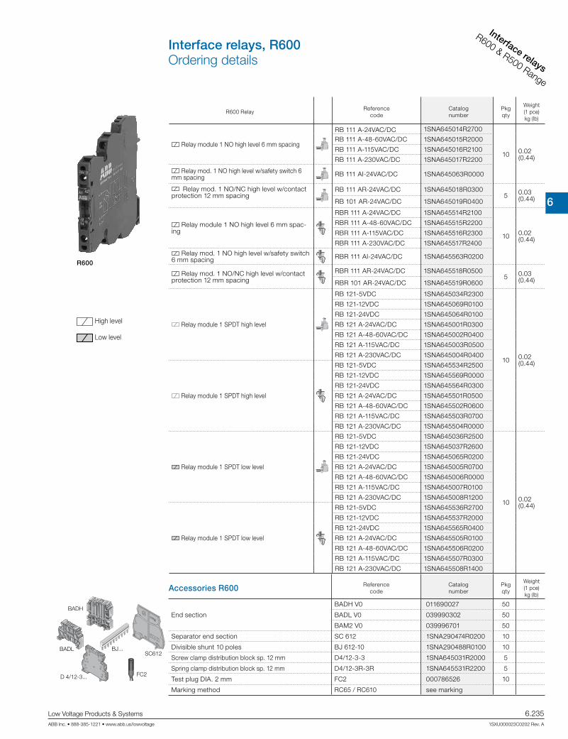
6
Interface relays
CR Range
Low Voltage Products & Systems 6.235ABB Inc. • 888-385-1221 • www.abb.us/lowvoltage 1SXU000023C0202 Rev. A
Interface relays
R600 & R500 Range
R600 Relay Reference
codeCatalognumber
Pkg qty
Weight(1 pce)kg (lb)
Relay module 1 NO high level 6 mm spacing
RB 111 A-24VAC/DC 1SNA645014R2700
10 0.02 (0.44)
RB 111 A-48-60VAC/DC 1SNA645015R2000
RB 111 A-115VAC/DC 1SNA645016R2100
RB 111 A-230VAC/DC 1SNA645017R2200
Relay mod. 1 NO high level w/safety switch 6 mm spacing RB 111 AI-24VAC/DC 1SNA645063R0000
Relay mod. 1 NO/NC high level w/contact protection 12 mm spacing
RB 111 AR-24VAC/DC 1SNA645018R03005 0.03
(0.44)RB 101 AR-24VAC/DC 1SNA645019R0400
Relay module 1 NO high level 6 mm spac-ing
RBR 111 A-24VAC/DC 1SNA645514R2100
10 0.02 (0.44)
RBR 111 A-48-60VAC/DC 1SNA645515R2200
RBR 111 A-115VAC/DC 1SNA645516R2300
RBR 111 A-230VAC/DC 1SNA645517R2400
Relay mod. 1 NO high level w/safety switch 6 mm spacing RBR 111 AI-24VAC/DC 1SNA645563R0200
Relay mod. 1 NO/NC high level w/contact protection 12 mm spacing
RBR 111 AR-24VAC/DC 1SNA645518R05005 0.03
(0.44)RBR 101 AR-24VAC/DC 1SNA645519R0600
Relay module 1 SPDT high level
RB 121-5VDC 1SNA645034R2300
10 0.02 (0.44)
RB 121-12VDC 1SNA645069R0100
RB 121-24VDC 1SNA645064R0100
RB 121 A-24VAC/DC 1SNA645001R0300
RB 121 A-48-60VAC/DC 1SNA645002R0400
RB 121 A-115VAC/DC 1SNA645003R0500
RB 121 A-230VAC/DC 1SNA645004R0400
Relay module 1 SPDT high level
RB 121-5VDC 1SNA645534R2500
RB 121-12VDC 1SNA645569R0000
RB 121-24VDC 1SNA645564R0300
RB 121 A-24VAC/DC 1SNA645501R0500
RB 121 A-48-60VAC/DC 1SNA645502R0600
RB 121 A-115VAC/DC 1SNA645503R0700
RB 121 A-230VAC/DC 1SNA645504R0000
Relay module 1 SPDT low level
RB 121-5VDC 1SNA645036R2500
10 0.02 (0.44)
RB 121-12VDC 1SNA645037R2600
RB 121-24VDC 1SNA645065R0200
RB 121 A-24VAC/DC 1SNA645005R0700
RB 121 A-48-60VAC/DC 1SNA645006R0000
RB 121 A-115VAC/DC 1SNA645007R0100
RB 121 A-230VAC/DC 1SNA645008R1200
Relay module 1 SPDT low level
RB 121-5VDC 1SNA645536R2700
RB 121-12VDC 1SNA645537R2000
RB 121-24VDC 1SNA645565R0400
RB 121 A-24VAC/DC 1SNA645505R0100
RB 121 A-48-60VAC/DC 1SNA645506R0200
RB 121 A-115VAC/DC 1SNA645507R0300
RB 121 A-230VAC/DC 1SNA645508R1400
Accessories R600 Referencecode
Catalognumber
Pkg qty
Weight(1 pce)kg (lb)
End section
BADH V0 011690027 50
BADL V0 039990302 50
BAM2 V0 039996701 50
Separator end section SC 612 1SNA290474R0200 10
Divisible shunt 10 poles BJ 612-10 1SNA290488R0100 10
Screw clamp distribution block sp. 12 mm D4/12-3-3 1SNA645031R2000 5
Spring clamp distribution block sp. 12 mm D4/12-3R-3R 1SNA645531R2200 5
Test plug DIA. 2 mm FC2 000786526 10
Marking method RC65 / RC610 see marking
R600
SC612BADL BJ...
FC2D 4/12-3...
BADH
High level
Low level
Interface relays, R600Ordering details

6
Interface re
lays
CR Range
6.236 Low Voltage Products & Systems
1SXU000023C0202 Rev. A ABB Inc. • 888-385-1221 • www.abb.us/lowvoltage
Interface re
lays
R600 & R500 Range
R600 Relay Reference
codeCatalognumber
Pkg qty
Weight(1 pce)kg (lb)
Relay mod. 1SPDT high level w/leakage current protec.
RB 121 AR-115VAC/DC 1SNA645046R0700
5 0.03 (0.066)
RB 121 AR-230VAC/DC 1SNA645011R2400
Relay mod. 1SPDT high level w/large coil voltage range RB 121 A 60-230VAC/DC 1SNA645020R0100
Relay mod. 1SPDT high level with switch RB 121 AI-24VAC/DC 1SNA645032R2100
Relay mod. 1SPDT high level with safety switch RB 121 AI-24VAC/DC 1SNA645009R1300
Relay module 1SPDT low level with switch RB 121 AI-24VAC/DC 1SNA645033R2200
Relay module 1SPDT low level with safety switch RB 121 AI-24VAC/DC 1SNA645010R0700
Relay mod. 1SPDT high level w/leakage current protec.
RB 121 AR-115VAC/DC 1SNA645546R0100
RB 121 AR-230VAC/DC 1SNA645511R2600
Relay mod. 1SPDT high level w/large coil voltage range RB 121 A 60-230VAC/DC 1SNA645520R0300
Relay mod. 1SPDT high level with switch RB 121 AI-24VAC/DC 1SNA645532R2300
Relay mod. 1SPDT high level with safety switch RB 121 AI-24VAC/DC 1SNA645509R1500
Relay module 1SPDT low level with switch RB 121 AI-24VAC/DC 1SNA645533R2400
Relay module 1SPDT low level with safety switch RB 121 AI-24VAC/DC 1SNA645510R0100
Relay module 1 DPDT low level
RB 122 A-24VAC/DC 1SNA645012R2500
5 0.03 (0.066)
RB 122 A-48-60VAC/DC 1SNA645040R1500
RB 122 A-115VAC/DC 1SNA645041R0200
RB 122 A-230VAC/DC 1SNA645013R2600
Relay module 1 DPDT low level
RBR 122 A-24VAC/DC 1SNA645512R2700
RBR 122 A-48-60VAC/DC 1SNA645540R1700
RBR 122 A-115VAC/DC 1SNA645541R0400
RBR 122 A-230VAC/DC 1SNA645513R2000
R600
Accessories R600Reference
codeCatalognumber
Pkg qty
Weight(1 pce)kg (lb)
End section
BADH V0 011690027 50
BADL V0 039990302 50
BAM2 V0 039996701 50
Separator end section SC 612 1SNA290474R0200 10
Divisible shunt 10 poles BJ 612-10 1SNA290488R0100 10
Screw clamp distribution block sp. 12 mm D4/12-3-3 1SNA645031R2000 5
Spring clamp distribution block sp. 12 mm D4/12-3R-3R 1SNA645531R2200 5
Test plug DIA. 2 mm FC2 000786526 10
Marking method RC65 / RC610 see marking
SC612BADL BJ...
FC2D 4/12-3...
BADH
High level
Low level
Interface relays, R600Ordering details

6
Interface relays
CR Range
Low Voltage Products & Systems 6.237ABB Inc. • 888-385-1221 • www.abb.us/lowvoltage 1SXU000023C0202 Rev. A
Interface relays
R600 & R500 Range
RB...121 - 5-12 V DC RB...121 A - 24 V AC/DCRB...121 A48-60-115-230 V AC/DC
RB...121 - 24 V DC
RB...122 A24-48-60 V AC/DC
RB...122 A115-230 V AC/DC
RB...121 AR
RB...121 AI RB...121 AI
autooff
manu
S2S1
RB...121 A
RB...121 - 5 V DC RB...121 A - 24 V AC/DC
RB...121 A48-60-115-230 V AC/DC
RB...121 - 12-24 V DC
RB...111 A - 24 V AC/DCRB...111 A48-60-115-230 V AC/DC RB...111 AR
RB...101 AR
RB...111 AI
autooff
manu
Interface relays, R600Connection diagrams

6
Interface re
lays
CR Range
6.238 Low Voltage Products & Systems
1SXU000023C0202 Rev. A ABB Inc. • 888-385-1221 • www.abb.us/lowvoltage
Interface re
lays
R600 & R500 Range
Technical data
Relay : 1NO or 1NC high level contact 10 mA to 6 A - 6 mm .236“ or 12 mm .472“ spacing
RB 111 A RB 111 AI RB 111 AR RB 101 AR
Relay characteristics coil
Rated voltage: +20%, -15% on DC ; 10%, -10% on AC 24 VAC/DC 48 VAC/DC 60 VAC/DC 115 VAC/DC
230 VAC/DC
± 10% on AC
± 10%-15% on DC
24 VAC/DC 24 VAC/DC 24 VAC/DC
Frequency 50/60 Hz
Power 0.24 W 0.34 W 0.54 W 0.46 W 0.8 W 0.24 W 0.24 W 0.24 W
Rated current 10 mA 7 mA 9 mA 4 mA 3.5 mA 10 mA 10 mA 10 mA
Drop-out voltage at 20°C 4.5 V 8 V 8 V 17 V 27 V 4.5 V 4.5 V 4.5 V
Status device green LED
Relay characteristics contact
Type 1 NO 1 NO + RC
Voltage switching range min./max. 12 V / 250 VAC
Current switching range min./max. 10 mA / 6 A
Load switching rangeAC1 min./max. 0.6 VA / 1500 VA (ohmic load)
DC1 min./max. 0.6 W / 140 W
Number of on-load operations 105 on AC15
Number of off-load operations 107
Operation speedF 5 ms 6 ms 7 ms 5 ms
O 8 ms 15 ms 8 ms
Bounce 1.2 ms
Insulation coil / contact 4000 V RMS 3800 V RMS 4000 V RMS
Resistance to shock coil / contact 4000 V RMS
Insulation contact / contact 1000 V RMS
Ambient temperaturestorage -40 °C to +80 °C
operating -20 °C to +70 °C 1)
Other characteristics Screw clamp Spring clamp
Body material grey UL 94 V0
Wire sizeSolid wire 0.2 - 4 mm² (24-12 AWG) 0.2-2.5 mm² (24-12 AWG)
Stranded wire 0.22 - 2.5 mm² (24-12 AWG)
Rated wire size 2.5 mm² (12 AWG)
Wire stripping length 9 mm (0.354 in)
Recommended screwdriver 3.5 mm (0.137 in)
Protection IP20 NEMA1
Recommended torque 0.4-0.6 Nm (3.5-5.3 lb.in)
Approvals , (pending) , , LRS , Reference standards CEI 947-7-1 / CEI 947-1 / CEI 1131-2 (in relevant parts) / CEI 60664-1 / CEM : IRC 1000-4-2, 3, 4, 5, 6.
1) Over 55°C, blocks have to be mounted on horizontal rail with 10 mm spacing between each block. For vertical rail mounting use temperature is 15°C less decreased.
center of rail
Screw clamp module
center of rail
Spring clamp module
Dimensional drawings
DC12 AC12 DC13 AC15 24 V 6 A 6 A 1 A 3 A 110/120 V 0.3 A 6 A 0.2 A 3 A 220/230 V 0.2 A 6 A 0.1 A 3 A
Limited load in CC
Current (Acc)
Volta
ge (V
cc)
Interface relays, R600Technical information
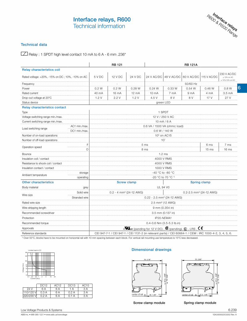
6
Interface relays
CR Range
Low Voltage Products & Systems 6.239ABB Inc. • 888-385-1221 • www.abb.us/lowvoltage 1SXU000023C0202 Rev. A
Interface relays
R600 & R500 Range
DC12 AC12 DC13 AC15 24 V 6 A 6 A 1 A 3 A 110/120 V 0.3 A 6 A 0.2 A 3 A 220/230 V 0.2 A 6 A 0.1 A 3 A
Technical data
Relay : 1 SPDT high level contact 10 mA to 6 A - 6 mm .236“
RB 121 RB 121A
Relay characteristics coil
Rated voltage: +20%, -15% on DC ; 10%, -10% on AC 5 V DC 12 V DC 24 V DC 24 V AC/DC 48 V AC/DC 60 V AC/DC 115 V AC/DC230 V AC/DC
± 10% on AC
± 10%-15% on DC
Frequency - 50/60 Hz
Power 0.2 W 0.2 W 0.28 W 0.24 W 0.33 W 0.54 W 0.46 W 0.8 W
Rated current 40 mA 16 mA 12 mA 10 mA 7 mA 9 mA 4 mA 3.5 mA
Drop-out voltage at 20°C 1.2 V 2.2 V 1.2 V 4.5 V 8 V 8 V 17 V 27 V
Status device green LED
Relay characteristics contact
Type 1 SPDT
Voltage switching range min./max. 12 V / 250 V AC
Current switching range min./max. 10 mA / 6 A
Load switching rangeAC1 min./max. 0.6 VA / 1500 VA (ohmic load)
DC1 min./max. 0.6 W / 140 W
Number of on-load operations 105 on AC15
Number of off-load operations 107
Operation speedF 5 ms 6 ms 7 ms
O 8 ms 15 ms 16 ms
Bounce 1.2 ms
Insulation coil / contact 4000 V RMS
Resistance to shock coil / contact 4000 V RMS
Insulation contact / contact 1000 V RMS
Ambient temperaturestorage -40 °C to -80 °C
operating -20 °C to 70 °C 1)
Other characteristics Screw clamp Spring clamp
Body material grey UL 94 V0
Wire sizeSolid wire 0.2 - 4 mm² (24-12 AWG) 0.2-2.5 mm² (24-12 AWG)
Stranded wire 0.22 - 2.5 mm² (24-12 AWG)
Rated wire size 2.5 mm² (12 AWG)
Wire stripping length 9 mm (0.354 in)
Recommended screwdriver 3.5 mm (0.137 in)
Protection IP20 NEMA1
Recommended torque 0.4-0.6 Nm (3.5-5.3 lb.in)
Approvals (pending for 12 V DC) , (pending), , LRS ,
Reference standards CEI 947-7-1 / CEI 947-1 / CEI 1131-2 (in relevant parts) / CEI 60664-1 / CEM : IRC 1000-4-2, 3, 4, 5, 6.1) Over 55°C, blocks have to be mounted on horizontal rail with 10 mm spacing between each block. For vertical rail mounting use temperature is 15°C less decreased.
center of rail
Screw clamp module
center of rail
Spring clamp module
Dimensional drawingsLimited load in CC
Current (Acc)
Volta
ge (V
cc)
Interface relays, R600Technical information

6
Interface re
lays
CR Range
6.240 Low Voltage Products & Systems
1SXU000023C0202 Rev. A ABB Inc. • 888-385-1221 • www.abb.us/lowvoltage
Interface re
lays
R600 & R500 Range
1) Over 55°C, blocks have to be mounted on horizontal rail with 10 mm spacing between each block. For vertical rail mounting use temperature is 15°C less decreased.
center of rail
Screw clamp module
center of rail
Spring clamp module
Dimensional drawings
Technical data
Relay : 1 SPDT low level with contact 1 mA upto 6 A - 6 m 0.236“ spacing
RB 121 RB 121 A
Relay characteristics coil
Rated voltage: +20%, -15% on DC ; 10%, -10% on AC 5 V DC 12 V DC 24 V DC 24 VAC/DC 48 VAC/DC 60 V AC/DC 115 V AC/DC230 V AC/DC
± 10% on AC
± 10%-15% on DC
Frequency 50/60 Hz
Power 0.2 W 0.2 W 0.28 W 0.24 W 0.33 W 0.54 W 0.46 W 0.8 W
Rated current 40 mA 16 mA 12 mA 10 mA 7 mA 9 mA 4 mA 3.5 mA
Drop-out voltage at 20°C 1.2 V 2.2 V 1.2 V 4.5 V 8 V 8 V 17 V 27 V
Status device green LED
Relay characteristics contact
Type 1 SPDT
Voltage switching range min./max. 5 V / 250 V AC
Current switching range min./max. 1 mA / 6 A
Load switching rangeAC1 min./max. 0.05 VA / 1500 VA (ohmic load)
DC1 min./max. 0.05 W / 140 W
Number of on-load operations 105 on AC15
Number of off-load operations 107
Operation speedF 5 ms 5 ms 5 ms 5 ms 5 ms 5 ms 6 ms 7 ms
O 8 ms 8 ms 8 ms 8 ms 8 ms 8 ms 15 ms 16 ms
Insulation coil / contact 4000 V RMS
Resistance to shock coil / contact 4000 V RMS
Insulation contact / contact 1000 V RMS
Ambient temperaturestorage -40 °C to -80 °C
operating -20 °C to 70 °C 1)
Other characteristics Screw clamp Spring clamp
Body material grey UL 94 V0
Wire sizeSolid wire 0.2 - 4 mm² (24-12 AWG) 0.2-2.5 mm² (24-12 AWG)
Stranded wire 0.22 - 2.5 mm² (24-12 AWG)
Rated wire size 2.5 mm² (12 AWG)
Wire stripping length 9 mm (0.354 in)
Recommended screwdriver 3.5 mm (0.137 in)
Protection IP20 NEMA1
Recommended torque 0.4-0.6 Nm (3.5-5.3 lb.in)
Approvals (pending for 24 V DC) , (pending) , , LRS ,
Reference standards CEI 947-7-1 / CEI 947-1 / CEI 1131-2 (in relevant parts) / CEI 60664-1 / CEM : IRC 1000-4-2, 3, 4, 5, 6.
DC12 AC12 DC13 AC15 24 V 6 A 6 A 1 A 3 A 110/120 V 0.3 A 6 A 0.2 A 3 A 220/230 V 0.2 A 6 A 0.1 A 3 A
Limited load in CC
Current (Acc)
Volta
ge (V
cc)
Interface relays, R600Technical information

6
Interface relays
CR Range
Low Voltage Products & Systems 6.241ABB Inc. • 888-385-1221 • www.abb.us/lowvoltage 1SXU000023C0202 Rev. A
Interface relays
R600 & R500 Range
1) Over 55°C, blocks have to be mounted on horizontal rail with 10 mm spacing between each block. For vertical rail mounting use temperature is 15°C less decreased.
center of rail
Screw clamp module
center of rail
Spring clamp module
Dimensional drawings
Technical data
Relay : 1 SPDT high level with switch or large coil voltage range or with leakage current protection 12 mm 0.472“ spacing Relay : 1 SPDT low level with switch - 12 mm 0.472“ spacing
RB 121 AR RB 121AI RB 121 AI RB 121 AI
Relay characteristics coil
Rated voltage: +20%, -15% on DC ; 10%, -10% on AC 115 V AC/DC230 V AC/DC
± 10% on AC
± 10%-15% on DC
24 VAC/DC 24 VAC/DC 60 to 253 VAC/DC
Frequency 50/60 Hz
Power 2 W 2.8 W 0.24 W 0.24 W 1 W
Rated current 18 mA 12 mA 10 mA 10 mA 4 mA max.
Drop-out voltage at 20°C 17 V 27 V 4.5 V 4.5 V 15 V
Permissible leakage current 1.6 mA 1 mA
Status device green LED
Relay characteristics contact
Type 1 SPDT
Voltage switching range min./max. 12 V / 250 V AC 5 V / 250 V 12 V / 250 V
Current switching range min./max. 10 mA / 6 A
Load switching rangeAC1 min./max. 0.6 VA / 1500 VA (ohmic load) 0.05 VA / 1500 VA
(ohmic load)0.6 VA / 1500 VA
(ohmic load)
DC1 min./max. 0.6 W / 140 W 0.05 W / 140 W 0.6 W / 140 W
Number of on-load operations 105 on AC15
Number of off-load operations 107
Operation speedF 6 ms 7 ms 5 ms 5 ms 5 ms 7 ms
O 15 ms 16 ms 8 ms 8 ms 8 ms 20 ms
Insulation coil / contact 4000 V RMS
Resistance to shock coil / contact 4000 V RMS
Insulation contact / contact 1000 V RMS
Ambient temperaturestorage -40 °C to -80 °C
operating -20 °C to 70 °C 1)
Other characteristics Screw clamp Spring clamp
Body material grey UL 94 V0
Wire sizeSolid wire 0.2 - 4 mm² (24-12 AWG) 0.2-2.5 mm² (24-12 AWG)
Stranded wire 0.22 - 2.5 mm² (24-12 AWG)
Rated wire size 2.5 mm² (12 AWG)
Wire stripping length 9 mm (0.354 in)
Recommended screwdriver 3.5 mm (0.137 in)
Protection IP20 NEMA1
Recommended torque 0.4-0.6 Nm (3.5-5.3 lb.in)
Approvals , (pending), , LRS ,
Reference standards CEI 947-7-1 / CEI 947-1 / CEI 1131-2 (in relevant parts) / CEI 60664-1 / CEM : IRC 1000-4-2, 3, 4, 5, 6.
DC12 AC12 DC13 AC15 24 V 6 A 6 A 1 A 3 A 110/120 V 0.3 A 6 A 0.2 A 3 A 220/230 V 0.2 A 6 A 0.1 A 3 A
Limited load in CC
Current (Acc)
Volta
ge (V
cc)
Interface relays, R600Technical information

6
Interface re
lays
CR Range
6.242 Low Voltage Products & Systems
1SXU000023C0202 Rev. A ABB Inc. • 888-385-1221 • www.abb.us/lowvoltage
Interface re
lays
R600 & R500 Range
Technical data
Relay : 1 DPDT low level contact 1 mA to 8 A - 12 mm 0.472“ spacing
RB ... 122A
Relay characteristics coil
Rated voltage: +20%, -15% on DC ; 10%, -10% on AC 24 V AC/DC 48 V AC/DC 60 V AC/DC 115 V AC/DC230 V AC/DC
± 10% on AC
± 10%-15% on DC
Frequency 50/60 Hz
Power 0.48 W 0.62 W 0.96 W 0.58 W 1.15 W
Rated current 20 mA 13 mA 16 mA 5 mA 5 mA
Drop-out voltage at 20°C 5.4 V 8.8 V 8.8 V 20 V 10 V
Status device green LED
Relay characteristics contact
Type 1 DPDT
Voltage switching range min./max. 5 V / 250 V DC - 250 V AC
Current switching range min./max. 1 mA / 8 A 1 mA / 5 A
Load switching rangeAC1 min./max. 5 mVA / 1500 VA (ohmic load)
DC1 min./max. 5 mW / 192 W
Number of on-load operations 105
Number of off-load operations 2 x 10⁷
Operation speedF 6 ms 10 ms 10 ms 6 ms 6 ms
O 10 ms 14 ms 14 ms 15 ms 15 ms
Bounce 1 ms
Insulation coil / contact 3500 V RMS
Resistance to shock coil / contact 3500 V RMS
Insulation contact / contact 3500 V RMS (between 2 contacts)
Ambient temperaturestorage -40 °C to -80 °C
operating -20 °C to 70 °C 1)
Other characteristics Screw clamp Spring clamp
Body material grey UL 94 V0
Wire sizeSolid wire 0.2 - 4 mm² (24-12 AWG) 0.2-2.5 mm² (24-12 AWG)
Stranded wire 0.22 - 2.5 mm² (24-12 AWG)
Rated wire size 2.5 mm² (12 AWG)
Wire stripping length 9 mm (0.354 in)
Recommended screwdriver 3.5 mm (0.137 in)
Protection IP20 NEMA1
Recommended torque 0.4-0.6 Nm (3.5-5.3 lb.in)
Approvals (pending for 12 V DC) , (pending), , LRS ,
Reference standards CEI 947-7-1 / CEI 947-1 / CEI 1131-2 (in relevant parts) / CEI 60664-1 / CEM : IRC 1000-4-2, 3, 4, 5, 6.
1) Over 55°C, blocks have to be mounted on horizontal rail with 10 mm spacing between each block. For vertical rail mounting use temperature is 15°C less decreased.
center of rail
Screw clamp module
center of rail
Spring clamp module
CURRENT (A)
Max. DC load breaking capacity
resistive load
Dimensional drawings
Interface relays, R600Technical information
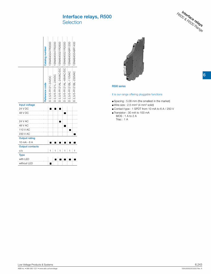
6
Interface relays
CR Range
Low Voltage Products & Systems 6.243ABB Inc. • 888-385-1221 • www.abb.us/lowvoltage 1SXU000023C0202 Rev. A
Interface relays
R600 & R500 Range
Cat
alo
g n
umb
er
1SN
A64
5047
R00
00
1SN
A64
5547
R02
00
1SN
A64
5021
R26
00
1SN
A64
5521
R20
00
1SN
A64
5049
R12
00
1SN
A64
5549
R14
00
Ref
eren
ce c
od
e
D 2
,5/5
-R12
1-24
VD
C
D 2
,5/5
-R12
1L-2
4VD
C
D 2
,5/5
-R12
1AL-
24VA
C/D
C
D 2
,5/5
-R12
1AL-
48VA
C/D
C
D 2
,5/5
-R12
1BL-
110V
AC
D 2
,5/5
-R12
1BL-
230V
AC
Input voltage
24 V DC
48 V DC
24 V AC
48 V AC
110 V AC
230 V AC
Output rating
10 mA - 6 A
Output contacts
c/o
Type
with LED
without LED
111111
R500 series
It is our range offering pluggable functions
Spacing : 5.08 mm (the smallest in the market) Wire size : 2.5 mm² (4 mm² solid) Contact type : 1 SPDT from 10 mA to 6 A / 250 V Transistor : 30 mA to 100 mA
MOS : 1 A to 2 A Triac : 1 A
Interface relays, R500Selection

6
Interface re
lays
CR Range
6.244 Low Voltage Products & Systems
1SXU000023C0202 Rev. A ABB Inc. • 888-385-1221 • www.abb.us/lowvoltage
Interface re
lays
R600 & R500 Range
Description of R500 Relay Reference
codeCatalognumber
Pkg qty
Weight(1 pce)kg (lb)
Relay module 1 SPDT high level D 2,5/5-R121-24VDC 1SNA607217R0200
10
0.032 (0.071)
Relay module with LED 1 SPDT high level
D 2,5/5-R121L-24VDC 1SNA607201R1300
D 2,5/5-R121AL-24VAC/DC 1SNA607231R0000
0.04 (0.088)
D 2,5/5-R121AL-48VAC/DC 1SNA607232R0100
D 2,5/5-R121BL-110VAC 1SNA607264R1100
D 2,5/5-R121BL-230VAC 1SNA607265R1200
R500 Accessories Reference
codeCatalognumber
Pkg qty
Weight(1 pce)kg (lb)
High end stop
BAMH 9,1 mm 011483600
50BAMH V0 9,1 mm 019483601
BADH 12 mm 011690027
Comb type jumper bar 2 to 22 poles consult us
Jumper bar 10 poles grey PCMS V0 1SNA205523R2200 8
Relay / Opto base D 2,5/5-MP 1SNA607224R0100
10
0.028 (0.062)Relay / Opto base with LED 24 VDC D 2,5/5-MP-24VDC 1SNA607222R0700
Relay / Opto base with LED 24 VAC/VDC D 2,5/5-MP-24VAC/DC 1SNA607260R2100
0.036 (0.0794)
Relay / Opto base with LED 48 VAC/VDC D 2,5/5-MP-48VAC/DC 1SNA607261R1600
Relay / Opto base with LED 110 VAC D 2,5/5-MP-110VAC 1SNA607266R1300
Relay / Opto base with LED 230 VAC D 2,5/5-MP-230VAC 1SNA607267R1400
Plug relay 24 V 1 SPDT 10 mA to 6 A BNMS R24V-1 1SNA031820R1400
Plug relay 24 V 1 SPDT 1 mA to 6 A BNMS R24V-2 1SNA031847R13004
Test device blue DCB 1) 1SNA105028R2100
Test plug DIA. 2 mm FC2 00078652610
Marking method RC55 see marking
R500
D 2.5/5-R121AL-24V
D 2.5/5-R121AL-48V D 2.5/5-R121BL
D 2.5/5-R121 D 2.5/5-R121L
BAMH
BADH
PCMS
BNMS R24V-...
DCB FC2
D2,5/5-MP...
1) Only on top decks
Connection diagrams
Interface relays, R500Ordering details

6
Interface relays
CR Range
Low Voltage Products & Systems 6.245ABB Inc. • 888-385-1221 • www.abb.us/lowvoltage 1SXU000023C0202 Rev. A
Interface relays
R600 & R500 Range
Technical data
Relay : 1 SPDT high level with contact 10 mA to 6 A - 5.08mm 0.200“ spacing
D 2.5/5-R121 D 2.5/5-R121L D 2.5/5-R121AL D 2.5/5-R121BL
Relay characteristics coil
Rated voltage: +20%, -15% on DC ; 10%, -10% on AC 24 V DC 24 V DC 24 V AC 24 V DC 48 V AC 48 V DC 110 V AC 230 V AC
Frequency 50/60 Hz 50/60 Hz 50/60 Hz 50/60 Hz
Power 0.17 W 0.3 W 0.35 W 0.35 W 0.44 W 0.47 W 1.08 W 2.13 W
Rated current 7 mA 12 mA 12.4 mA 10 mA 7.6 mA 6.8 mA 8.4 mA 8 mA
Drop-out voltage at 20°C 2.4 V 2.4 V 4.8 V 4.8 V 10 V 10 V 25 V 45 V
Status device green LED
Relay characteristics contact
Type 1 SPDT
Voltage switching range min./max. 12 V / 250 V AC
Current switching range min./max. 10 mA / 6 A
Load switching rangeAC1 min./max. 0.6 VA / 1500 VA (ohmic load)
DC1 min./max. 0.6 W / 140 W
Number of on-load operations 105 on AC15
Number of off-load operations 10 x 107
Operation speedF 5 ms 5 ms 5 ms 5 ms 5 ms 5 ms 6 ms 7 ms
O 8 ms 8 ms 15 ms 15 ms 15 ms 15 ms 15 ms 15 ms
Insulation coil / contact 4000 V RMS
Resistance to shock coil / contact 4000 V RMS
Insulation contact / contact 1000 V RMS
Ambient temperaturestorage -40 °C to -80 °C
operating See derating curves
Other characteristics
Body material grey UL 94 V0
Wire sizeSolid wire 0.2 - 4 mm² (24-12 AWG)
Stranded wire 0.22 - 2.5 mm² (24-12 AWG)
Rated wire size 2.5 mm² (12 AWG)
Wire stripping length 10 mm (0.394 in)
Recommended screwdriver 3.5 mm (0.137 in)
Protection IP20 NEMA1
Recommended torque 0.4-0.6 Nm (3.5-5.3 lb.in)
Approvals (pending) ,
Reference standards CEI 947-7-1 / CEI 947-1 / CEI 1131-2 (in relevant parts) / CEI 60664-1 / CEM : IRC 1000-4-2, 3, 4, 5, 6.
Dimensional drawings
D 2,5/5-R121
1 : 24 V 2 : 48 V 3 : 110 V 4 : 230 V
DC12 AC12 DC13 AC15 24 V 6 A 6 A 1 A 3 A 110/120 V 0.3 A 6 A 0.2 A 3 A 220/230 V 0.2 A 6 A 0.1 A 3 A
Limited load in CC
Current (Acc)
Volta
ge
(Vcc
)Interface relays, R500Technical information

6
Interface re
lays
CR Range
6.246 Low Voltage Products & Systems
1SXU000023C0202 Rev. A ABB Inc. • 888-385-1221 • www.abb.us/lowvoltage
Interface re
lays
R600 & R500 Range

6
Interface relays
CR Range
Low Voltage Products & Systems 6.247ABB Inc. • 888-385-1221 • www.abb.us/lowvoltage 1SXU000023C0202 Rev. A
Optocouplers
R600 & R500 Range
OptocouplersR600 & R500
Opt
ocou
pler
sR
600
& R
500

6
Interface re
lays
CR Range
6.248 Low Voltage Products & Systems
1SXU000023C0202 Rev. A ABB Inc. • 888-385-1221 • www.abb.us/lowvoltage
Optocouplers
R600 & R500 RangeR600 OptocouplersSelection
Ref
eren
ce c
ode
OB
IC 0
100
5-12
VD
C
OB
RIC
010
0 5-
12V
DC
OB
IC 0
100
24V
DC
OB
RIC
010
0 24
VD
C
OB
IC 0
100
48-6
0VA
C/D
C
OB
RIC
010
0 48
-60V
AC
/DC
OB
IC 0
100
115-
230V
AC
/DC
OB
RIC
010
0 11
5-23
0VA
C/D
C
OB
OC
100
0-5-
12V
DC
OB
RO
C 1
000-
5-12
VD
C
OB
OC
100
0-24
VD
C
OB
OC
150
0-24
VAC
/DC
OB
OC
500
0-24
VD
C
OB
RO
C 1
000-
24V
DC
OB
RO
C 1
500-
24VA
C/D
C
OB
RO
C 5
000-
24V
DC
OB
OC
100
0-48
-60V
AC
/DC
OB
RO
C 1
000-
48-6
0VA
C/D
C
OB
OC
100
0-11
5VA
C/D
C
OB
OC
500
0-11
5VA
C/D
C
OB
RO
C 1
000-
115V
AC
/DC
OB
RO
C 5
000-
115V
AC
/DC
OB
OC
100
0-23
0VA
C/D
C
OB
OC
500
0-23
0VA
C/D
C
OB
RO
C 1
000-
230V
AC
/DC
OB
RO
C 5
000-
230V
AC
/DC
OB
OA
100
0-24
VD
C
OB
OA
200
0-24
VD
C
OB
RO
A 1
000-
24V
DC
OB
RO
A 2
000-
24V
DC
OB
OA
100
0-48
-60V
AC
/DC
OB
RO
A 1
000-
48-6
0VA
C/D
C
OB
OA
100
0-11
5VA
C/D
C
OB
RO
A 1
000-
115V
AC
/DC
OB
OA
100
0-23
0VA
C/D
C
OB
RO
A 1
000-
230V
AC
/DC
Cat
alog
num
ber
1SN
A64
5047
R00
00
1SN
A64
5547
R02
00
1SN
A64
5021
R26
00
1SN
A64
5521
R20
00
1SN
A64
5049
R12
00
1SN
A64
5549
R14
00
1SN
A64
5022
R27
00
1SN
A64
5522
R21
00
1SN
A64
5050
R17
00
1SN
A64
5550
R11
00
1SN
A64
5051
R04
00
1SN
A64
5025
R22
00
1SN
A64
5024
R21
00
1SN
A64
5551
R06
00
1SN
A64
5525
R24
00
1SN
A64
5524
R23
00
1SN
A64
5053
R06
00
1SN
A64
5553
R00
00
1SN
A64
5054
R07
00
1SN
A64
5058
R13
00
1SN
A64
5554
R01
00
1SN
A64
5558
R15
00
1SN
A64
5026
R23
00
1SN
A64
5059
R14
00
1SN
A64
5526
R25
00
1SN
A64
5559
R16
00
1SN
A64
5027
R24
00
1SN
A64
5029
R06
00
1SN
A64
5527
R26
00
1SN
A64
5529
R00
00
1SN
A64
5061
R06
00
1SN
A64
5561
R00
00
1SN
A64
5062
R07
00
1SN
A64
5562
R01
00
1SN
A64
5028
R05
00
1SN
A64
5528
R07
00
Input voltage5 - 12 V DC
24 V DC
48 - 60 V DC
115 - 230 V DC
115 V DC
230 V DC
24 V AC
48 - 60 V AC
115-230 V AC
115 V AC
230 V AC
Output rating
100 mA
2 A
5 A
1 A
Output voltage
58 V DC
400 V AC
Terminal type
Screw
Spring
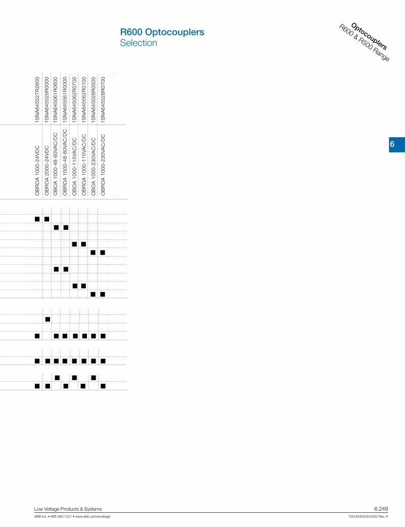
6
Interface relays
CR Range
Low Voltage Products & Systems 6.249ABB Inc. • 888-385-1221 • www.abb.us/lowvoltage 1SXU000023C0202 Rev. A
Optocouplers
R600 & R500 Range
R600 OptocouplersSelection
Ref
eren
ce c
ode
OB
IC 0
100
5-12
VD
C
OB
RIC
010
0 5-
12V
DC
OB
IC 0
100
24V
DC
OB
RIC
010
0 24
VD
C
OB
IC 0
100
48-6
0VA
C/D
C
OB
RIC
010
0 48
-60V
AC
/DC
OB
IC 0
100
115-
230V
AC
/DC
OB
RIC
010
0 11
5-23
0VA
C/D
C
OB
OC
100
0-5-
12V
DC
OB
RO
C 1
000-
5-12
VD
C
OB
OC
100
0-24
VD
C
OB
OC
150
0-24
VAC
/DC
OB
OC
500
0-24
VD
C
OB
RO
C 1
000-
24V
DC
OB
RO
C 1
500-
24VA
C/D
C
OB
RO
C 5
000-
24V
DC
OB
OC
100
0-48
-60V
AC
/DC
OB
RO
C 1
000-
48-6
0VA
C/D
C
OB
OC
100
0-11
5VA
C/D
C
OB
OC
500
0-11
5VA
C/D
C
OB
RO
C 1
000-
115V
AC
/DC
OB
RO
C 5
000-
115V
AC
/DC
OB
OC
100
0-23
0VA
C/D
C
OB
OC
500
0-23
0VA
C/D
C
OB
RO
C 1
000-
230V
AC
/DC
OB
RO
C 5
000-
230V
AC
/DC
OB
OA
100
0-24
VD
C
OB
OA
200
0-24
VD
C
OB
RO
A 1
000-
24V
DC
OB
RO
A 2
000-
24V
DC
OB
OA
100
0-48
-60V
AC
/DC
OB
RO
A 1
000-
48-6
0VA
C/D
C
OB
OA
100
0-11
5VA
C/D
C
OB
RO
A 1
000-
115V
AC
/DC
OB
OA
100
0-23
0VA
C/D
C
OB
RO
A 1
000-
230V
AC
/DC
Cat
alog
num
ber
1SN
A64
5047
R00
00
1SN
A64
5547
R02
00
1SN
A64
5021
R26
00
1SN
A64
5521
R20
00
1SN
A64
5049
R12
00
1SN
A64
5549
R14
00
1SN
A64
5022
R27
00
1SN
A64
5522
R21
00
1SN
A64
5050
R17
00
1SN
A64
5550
R11
00
1SN
A64
5051
R04
00
1SN
A64
5025
R22
00
1SN
A64
5024
R21
00
1SN
A64
5551
R06
00
1SN
A64
5525
R24
00
1SN
A64
5524
R23
00
1SN
A64
5053
R06
00
1SN
A64
5553
R00
00
1SN
A64
5054
R07
00
1SN
A64
5058
R13
00
1SN
A64
5554
R01
00
1SN
A64
5558
R15
00
1SN
A64
5026
R23
00
1SN
A64
5059
R14
00
1SN
A64
5526
R25
00
1SN
A64
5559
R16
00
1SN
A64
5027
R24
00
1SN
A64
5029
R06
00
1SN
A64
5527
R26
00
1SN
A64
5529
R00
00
1SN
A64
5061
R06
00
1SN
A64
5561
R00
00
1SN
A64
5062
R07
00
1SN
A64
5562
R01
00
1SN
A64
5028
R05
00
1SN
A64
5528
R07
00
Input voltage5 - 12 V DC
24 V DC
48 - 60 V DC
115 - 230 V DC
115 V DC
230 V DC
24 V AC
48 - 60 V AC
115-230 V AC
115 V AC
230 V AC
Output rating
100 mA
2 A
5 A
1 A
Output voltage
58 V DC
400 V AC
Terminal type
Screw
Spring
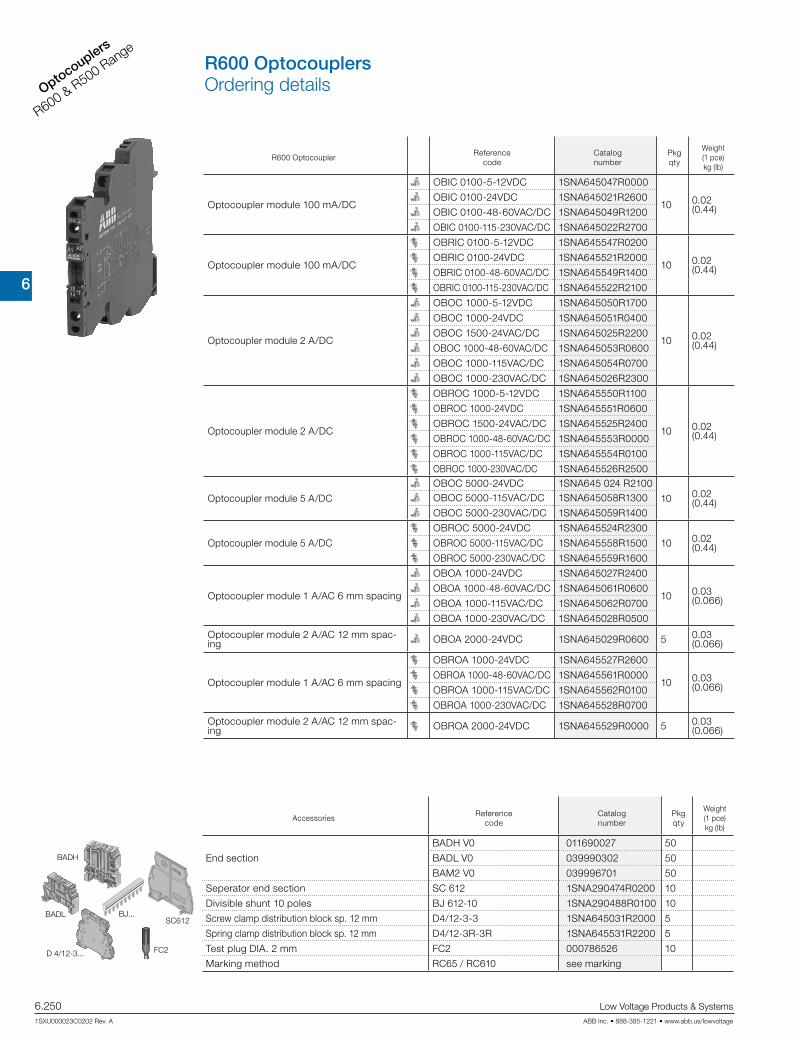
6
Interface re
lays
CR Range
6.250 Low Voltage Products & Systems
1SXU000023C0202 Rev. A ABB Inc. • 888-385-1221 • www.abb.us/lowvoltage
Optocouplers
R600 & R500 Range
R600 Optocoupler Reference
codeCatalognumber
Pkg qty
Weight(1 pce)kg (lb)
Optocoupler module 100 mA/DC
OBIC 0100-5-12VDC 1SNA645047R0000
10 0.02 (0.44)
OBIC 0100-24VDC 1SNA645021R2600
OBIC 0100-48-60VAC/DC 1SNA645049R1200
OBIC 0100-115-230VAC/DC 1SNA645022R2700
Optocoupler module 100 mA/DC
OBRIC 0100-5-12VDC 1SNA645547R0200
10 0.02 (0.44)
OBRIC 0100-24VDC 1SNA645521R2000
OBRIC 0100-48-60VAC/DC 1SNA645549R1400
OBRIC 0100-115-230VAC/DC 1SNA645522R2100
Optocoupler module 2 A/DC
OBOC 1000-5-12VDC 1SNA645050R1700
10 0.02 (0.44)
OBOC 1000-24VDC 1SNA645051R0400
OBOC 1500-24VAC/DC 1SNA645025R2200
OBOC 1000-48-60VAC/DC 1SNA645053R0600
OBOC 1000-115VAC/DC 1SNA645054R0700
OBOC 1000-230VAC/DC 1SNA645026R2300
Optocoupler module 2 A/DC
OBROC 1000-5-12VDC 1SNA645550R1100
10 0.02 (0.44)
OBROC 1000-24VDC 1SNA645551R0600
OBROC 1500-24VAC/DC 1SNA645525R2400
OBROC 1000-48-60VAC/DC 1SNA645553R0000
OBROC 1000-115VAC/DC 1SNA645554R0100
OBROC 1000-230VAC/DC 1SNA645526R2500
Optocoupler module 5 A/DC
OBOC 5000-24VDC 1SNA645 024 R2100
10 0.02 (0.44)OBOC 5000-115VAC/DC 1SNA645058R1300
OBOC 5000-230VAC/DC 1SNA645059R1400
Optocoupler module 5 A/DC
OBROC 5000-24VDC 1SNA645524R2300
10 0.02 (0.44)OBROC 5000-115VAC/DC 1SNA645558R1500
OBROC 5000-230VAC/DC 1SNA645559R1600
Optocoupler module 1 A/AC 6 mm spacing
OBOA 1000-24VDC 1SNA645027R2400
10 0.03 (0.066)
OBOA 1000-48-60VAC/DC 1SNA645061R0600
OBOA 1000-115VAC/DC 1SNA645062R0700
OBOA 1000-230VAC/DC 1SNA645028R0500
Optocoupler module 2 A/AC 12 mm spac-ing OBOA 2000-24VDC 1SNA645029R0600 5 0.03
(0.066)
Optocoupler module 1 A/AC 6 mm spacing
OBROA 1000-24VDC 1SNA645527R2600
10 0.03 (0.066)
OBROA 1000-48-60VAC/DC 1SNA645561R0000
OBROA 1000-115VAC/DC 1SNA645562R0100
OBROA 1000-230VAC/DC 1SNA645528R0700
Optocoupler module 2 A/AC 12 mm spac-ing OBROA 2000-24VDC 1SNA645529R0000 5 0.03
(0.066)
AccessoriesReference
codeCatalognumber
Pkg qty
Weight(1 pce)kg (lb)
End section
BADH V0 011690027 50
BADL V0 039990302 50
BAM2 V0 039996701 50
Seperator end section SC 612 1SNA290474R0200 10
Divisible shunt 10 poles BJ 612-10 1SNA290488R0100 10
Screw clamp distribution block sp. 12 mm D4/12-3-3 1SNA645031R2000 5
Spring clamp distribution block sp. 12 mm D4/12-3R-3R 1SNA645531R2200 5
Test plug DIA. 2 mm FC2 000786526 10
Marking method RC65 / RC610 see marking
SC612BADL BJ...
FC2D 4/12-3...
BADH
R600 OptocouplersOrdering details

6
Interface relays
CR Range
Low Voltage Products & Systems 6.251ABB Inc. • 888-385-1221 • www.abb.us/lowvoltage 1SXU000023C0202 Rev. A
Optocouplers
R600 & R500 Range
OB...IC 0100 - 5-12 V DC115-230 V AC/DC
OB...IC 010024 V DC
24-48-60 V AC/DC
OB...OC 1000 - 5-12 V DC
OB...OC 1500 - 24 V AC/DC OB...OC 1000
24 V DC48-60-115-230 V AC/DC
OB...OC 500024 V DC
24-48-60-115-230 V AC/DC
OB...OA 100024 V DC
48-60-115-230 V AC/DC OB...OA 2000 - 24 V DC
R600 OptocouplersConnection diagrams

6
Interface re
lays
CR Range
6.252 Low Voltage Products & Systems
1SXU000023C0202 Rev. A ABB Inc. • 888-385-1221 • www.abb.us/lowvoltage
Optocouplers
R600 & R500 Range
Technical data
Optocoupler : 5 to 58 V DC output / 100 mA - 6 mm 0.236“ spacing
OB...IC 0100
Relay characteristics coil
Input voltage: +20%, -15% on DC ; 10%, -10% on AC 5 V DC - 12 V DC 24 V DC 48 V AC/DC 60 V AC/DC 115 V AC/DC 230 V AC/DC
Frequency 50 / 60 Hz
Input current AC/DC 5 mA 9 mA 4 mA 4 mA 5 mA 7 mA /16 mA
11.5 mA /25 mA
Pull-in voltage at Is=100% 4 V 15 V 25 V 60 V AC / 70 V DC
Switching time C / O 10 µs / 500 µs
Operating frequency 1000 Hz 5 ms / 20 ms 5 ms / 15 ms
Permissible leakage current 20 Hz
Output 0.9 mA 1 mA 0.9 mA 1.6 mA
Output voltage 4.5 to 58 V DC
Output current min. 1 mA
Output current max. 100 mA
Output leakage current at Umax. < 50 µA
Residual voltage at I max and U ratedtypical 1 V
max 1.3 V
Frequency on inductive load
Isolation Input / Output input / Output 2500 V RMS
Temperaturestorage -40...+80 °C
operating -20...+70 °C 1)
Other characteristics Screw clamp Spring clamp
Body material grey UL 94 V0
Wire sizeSolid wire 0.2 - 4 mm² (24-12 AWG) 0.2-2.5 mm² (24-12 AWG)
Stranded wire 0.22 - 2.5 mm² (24-12 AWG)
Rated wire size 2.5 mm² (12 AWG)
Wire stripping length 9 mm (0.354 in)
Recommended screwdriver 3.5 mm (0.137 in)
Protection IP20 NEMA1
Recommended torque 0.4-0.6 Nm (3.5-5.3 lb.in)
Approvals (pending for 12 V DC) , (pending), , LRS ,
Reference standards CEI 947-7-1 / CEI 947-1 / CEI 1131-2 (in relevant parts) / CEI 60664-1 / CEM : IRC 1000-4-2, 3, 4, 5, 6.
1) Over 55°C, blocks have to be mounted on horizontal rail with 10 mm spacing between each block. For vertical rail mounting use temperature is 15°C less decreased.
center of rail
Screw clamp module
center of rail
Spring clamp module
Dimensional drawings
R600 OptocouplersTechnical data

6
Interface relays
CR Range
Low Voltage Products & Systems 6.253ABB Inc. • 888-385-1221 • www.abb.us/lowvoltage 1SXU000023C0202 Rev. A
Optocouplers
R600 & R500 Range
Technical data
Optocoupler : 5 to 58 V DC output / 2 A - 6 mm 0.236“ spacing
OB...IC 0100OB..OC
1500OB...OC 1000
Relay characteristics coil
Input voltage: +20%, -15% on DC ; 10%, -10% on AC 5 V DC - 12 V DC 24 V DC 24 V AC/DC 48 V AC/DC 60 V AC/DC 115 V AC/DC
230 V AC/DC
Frequency 50 / 60 Hz
Input current 5 mA 9 mA 4 mA 6.3 mA 4 mA 5.1 mA 4.2 mA 4 mA
Pull-in voltage at Is=100% 4 V 15 V 15 V 27 V 50 V 80 V
Switching time C / O 15 µs / 250 µs 30 µs / 400 µs 1 ms / 7 ms 5 ms / 20 ms 500 µs /
10 ms1 ms / 15 ms
Operating frequency 2000 Hz 1000 Hz 60 Hz 20 Hz
Permissible leakage current 1 mA 0.8 mA 0.9 mA 1 mA 0.3 mA
Output
Output voltage 4.5 to 58 V DC
Output current min. 1 mA
Output current max. 2 A
Output leakage current at Umax. < 50 µA
Redidual voltage at I max and U ratedtypical 0.1 V
max 0.5 V
Frequency on inductive load
Isolation Input / Output input / Output 2500 V RMS
Temperaturestorage -40...+80 °C
operating -20...+70 °C 1)
Other characteristics Screw clamp Spring clamp
Body material grey UL 94 V0
Wire sizeSolid wire 0.2 - 4 mm² (24-12 AWG) 0.2-2.5 mm² (24-12 AWG)
Stranded wire 0.22 - 2.5 mm² (24-12 AWG)
Rated wire size 2.5 mm² (12 AWG)
Wire stripping length 9 mm (0.354 in)
Recommended screwdriver 3.5 mm (0.137 in)
Protection IP20 NEMA1
Recommended torque 0.4-0.6 Nm (3.5-5.3 lb.in)
Approvals (pending for 12 V DC) , (pending), , LRS ,
Reference standards CEI 947-7-1 / CEI 947-1 / CEI 1131-2 (in relevant parts) / CEI 60664-1 / CEM : IRC 1000-4-2, 3, 4, 5, 6.1) Over 55°C, blocks have to be mounted on horizontal rail with 10 mm spacing between each block. For vertical rail mounting use temperature is 15°C less decreased.
center of rail
Screw clamp module
center of rail
Spring clamp module
Dimensional drawings
R600 OptocouplersTechnical data

6
Interface re
lays
CR Range
6.254 Low Voltage Products & Systems
1SXU000023C0202 Rev. A ABB Inc. • 888-385-1221 • www.abb.us/lowvoltage
Optocouplers
R600 & R500 Range
Technical data
Optocoupler : 5 to 58 V DC output / 5 A - 6 mm 0.236“ spacing
OB... OC 5000
Input
Input voltage 24 V DC 115 V AC/DC 230 V AC/DC
Frequency 50 / 60 Hz 50 / 60 Hz
Input current 5.4 mA 4.2 mA 4 mA
Pull-in voltage at Is=100% 12 V 50 V 80 V
Switching time C / O 30 µs / 400 µs 500 µs / 10 ms 1ms / 15 ms
Operating frequency 1000 Hz 50 Hz 35 Hz
Permissible leakage current 0.8 mA 0.3 mA 0.3 mA
Output
Output voltage 4.5- 58 V DC
Output current min. 25 mA
Output current max. 1 A
Output leakage current at Umax. < 0.50 mA
Redidual voltage at I max and U ratedtypical 1 V
max 1.6 V
Frequency on inductive load See Note 1
Isolation Input / Output input / Output 2500 V RMS
Temperature
Ambient temperature storage -40...+80 °C
operating See derating curve
Other characteristics
Body material grey UL 94 V0
Wire sizeSolid wire 0.2 - 4 mm² (24-12 AWG)
Stranded wire 0.22 - 2.5 mm² (24-12 AWG)
Rated wire size 2.5 mm² (12 AWG)
Wire stripping length 10 mm (0.394 in)
Recommended screwdriver 3.5 mm (0.137 in)
Protection IP20 NEMA1
Recommended torque 0.4-0.6 Nm (3.5-5.3 lb.in)
Approvals (pending),
Reference standards CEI 947-7-1 / CEI 947-1 / CEI 1131-2 (in relevant parts) / CEI 60664-1 / CEM : IRC 1000-4-2, 3, 4, 5, 6.
Dimensional drawings
center of rail
Screw clamp module
center of rail
Spring clamp module
R600 OptocouplersTechnical data
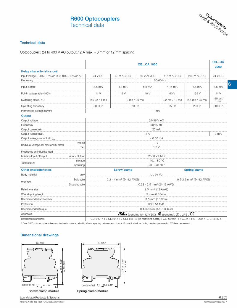
6
Interface relays
CR Range
Low Voltage Products & Systems 6.255ABB Inc. • 888-385-1221 • www.abb.us/lowvoltage 1SXU000023C0202 Rev. A
Optocouplers
R600 & R500 Range
Technical data
Optocoupler : 24 to 400 V AC output / 2 A max. - 6 mm or 12 mm spacing
OB...OA 1000OB...OA
2000
Relay characteristics coil
Input voltage: +20%, -15% on DC ; 10%, -10% on AC 24 V DC 48 V AC/DC 60 V AC/DC 115 V AC/DC 230 V AC/DC 24 V DC
Frequency 50/60 Hz
Input current 3.6 mA 4.3 mA 5.5 mA 4.15 mA 4.6 mA 3.6 mA
Pull-in voltage at Is=100% 14 V 15 V 18 V 60 V 135 V 14 V
Switching time C / O 150 µs / 1 ms 3 ms / 30 ms 2.2 ms / 18 ms 2.5 ms / 25 ms 150 µs / 1 ms
Operating frequency 500 Hz 20 Hz 25 Hz 20 Hz 500 Hz
Permissible leakage current 1 mA
Output
Output voltage 24-58 V AC
Frequency 50/60 Hz
Output current min. 25 mA
Output current max. 1 A 2 mA
Output leakage current at Umax. < 0.50 mA
Redidual voltage at I max and U ratedtypical 1 V
max 1.6 V
Frequency on inductive load
Isolation Input / Output input / Output 2500 V RMS
Temperaturestorage -40...+80 °C
operating -20...+70 °C 1)
Other characteristics Screw clamp Spring clamp
Body material grey UL 94 V0
Wire sizeSolid wire 0.2 - 4 mm² (24-12 AWG) 0.2-2.5 mm² (24-12 AWG)
Stranded wire 0.22 - 2.5 mm² (24-12 AWG)
Rated wire size 2.5 mm² (12 AWG)
Wire stripping length 9 mm (0.354 in)
Recommended screwdriver 3.5 mm (0.137 in)
Protection IP20 NEMA1
Recommended torque 0.4-0.6 Nm (3.5-5.3 lb.in)
Approvals (pending for 12 V DC) , (pending), , LRS ,
Reference standards CEI 947-7-1 / CEI 947-1 / CEI 1131-2 (in relevant parts) / CEI 60664-1 / CEM : IRC 1000-4-2, 3, 4, 5, 6.
Dimensional drawings
center of rail
Screw clamp module
center of rail
Spring clamp module
R600 OptocouplersTechnical data
1) Over 55°C, blocks have to be mounted on horizontal rail with 10 mm spacing between each block. For vertical rail mounting use temperature is 15°C less decreased.
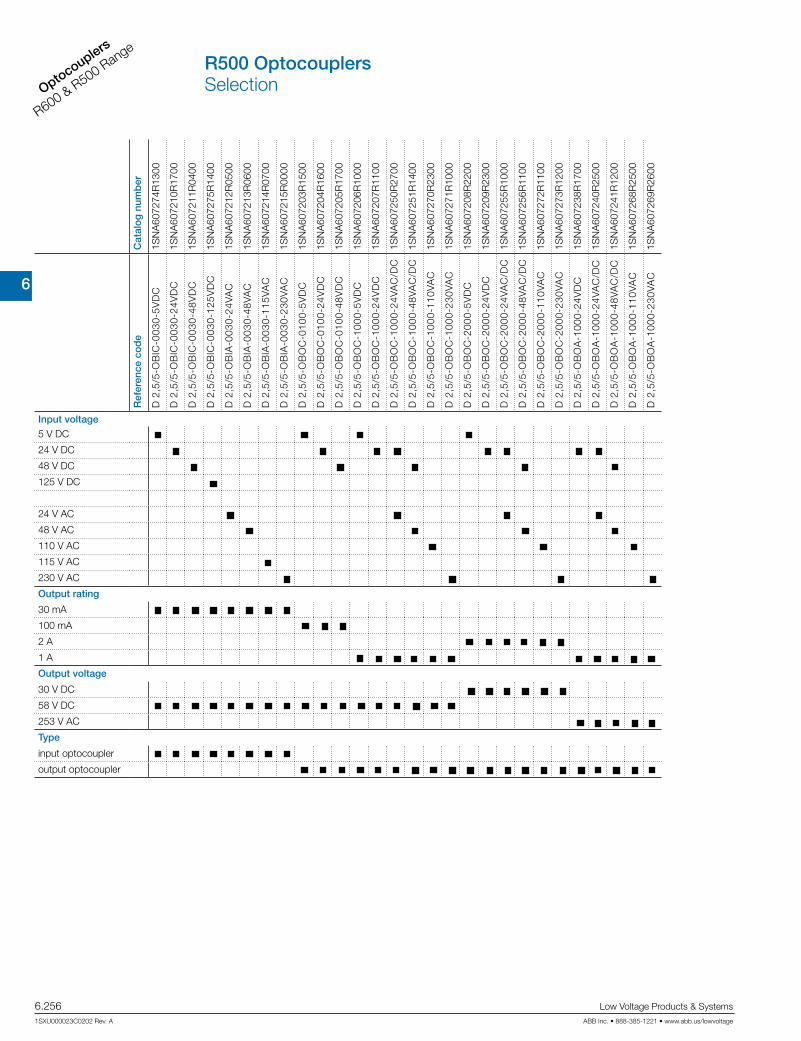
6
Interface re
lays
CR Range
6.256 Low Voltage Products & Systems
1SXU000023C0202 Rev. A ABB Inc. • 888-385-1221 • www.abb.us/lowvoltage
Optocouplers
R600 & R500 Range
Cat
alo
g n
umb
er
1SN
A60
7274
R13
00
1SN
A60
7210
R17
00
1SN
A60
7211
R04
00
1SN
A60
7275
R14
00
1SN
A60
7212
R05
00
1SN
A60
7213
R06
00
1SN
A60
7214
R07
00
1SN
A60
7215
R00
00
1SN
A60
7203
R15
00
1SN
A60
7204
R16
00
1SN
A60
7205
R17
00
1SN
A60
7206
R10
00
1SN
A60
7207
R11
00
1SN
A60
7250
R27
00
1SN
A60
7251
R14
00
1SN
A60
7270
R23
00
1SN
A60
7271
R10
00
1SN
A60
7208
R22
00
1SN
A60
7209
R23
00
1SN
A60
7255
R10
00
1SN
A60
7256
R11
00
1SN
A60
7272
R11
00
1SN
A60
7273
R12
00
1SN
A60
7238
R17
00
1SN
A60
7240
R25
00
1SN
A60
7241
R12
00
1SN
A60
7268
R25
00
1SN
A60
7269
R26
00
Ref
eren
ce c
od
e
D 2
,5/5
-OB
IC-0
030-
5VD
C
D 2
,5/5
-OB
IC-0
030-
24V
DC
D 2
,5/5
-OB
IC-0
030-
48V
DC
D 2
,5/5
-OB
IC-0
030-
125V
DC
D 2
,5/5
-OB
IA-0
030-
24VA
C
D 2
,5/5
-OB
IA-0
030-
48VA
C
D 2
,5/5
-OB
IA-0
030-
115V
AC
D 2
,5/5
-OB
IA-0
030-
230V
AC
D 2
,5/5
-OB
OC
-010
0-5V
DC
D 2
,5/5
-OB
OC
-010
0-24
VD
C
D 2
,5/5
-OB
OC
-010
0-48
VD
C
D 2
,5/5
-OB
OC
-100
0-5V
DC
D 2
,5/5
-OB
OC
-100
0-24
VD
C
D 2
,5/5
-OB
OC
-100
0-24
VAC
/DC
D 2
,5/5
-OB
OC
-100
0-48
VAC
/DC
D 2
,5/5
-OB
OC
-100
0-11
0VA
C
D 2
,5/5
-OB
OC
-100
0-23
0VA
C
D 2
,5/5
-OB
OC
-200
0-5V
DC
D 2
,5/5
-OB
OC
-200
0-24
VD
C
D 2
,5/5
-OB
OC
-200
0-24
VAC
/DC
D 2
,5/5
-OB
OC
-200
0-48
VAC
/DC
D 2
,5/5
-OB
OC
-200
0-11
0VA
C
D 2
,5/5
-OB
OC
-200
0-23
0VA
C
D 2
,5/5
-OB
OA
-100
0-24
VD
C
D 2
,5/5
-OB
OA
-100
0-24
VAC
/DC
D 2
,5/5
-OB
OA
-100
0-48
VAC
/DC
D 2
,5/5
-OB
OA
-100
0-11
0VA
C
D 2
,5/5
-OB
OA
-100
0-23
0VA
C
Input voltage
5 V DC
24 V DC
48 V DC
125 V DC
24 V AC
48 V AC
110 V AC
115 V AC
230 V AC
Output rating
30 mA
100 mA
2 A
1 A
Output voltage
30 V DC
58 V DC
253 V AC
Type
input optocoupler
output optocoupler
R500 OptocouplersSelection
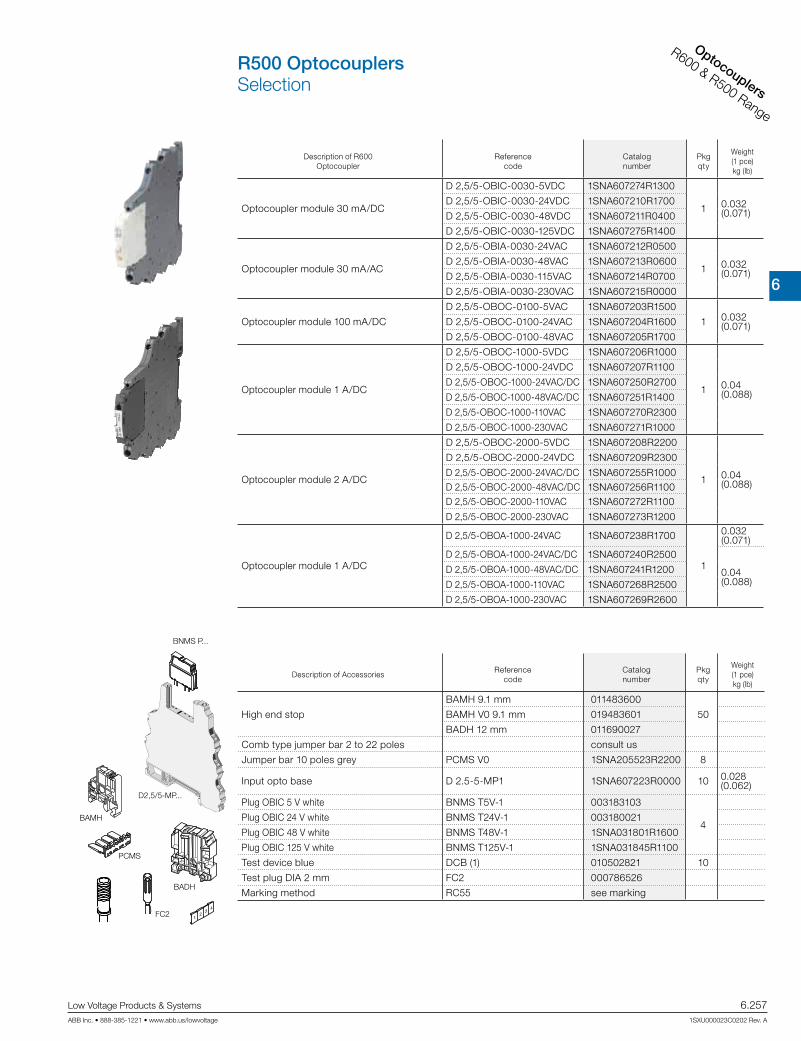
6
Interface relays
CR Range
Low Voltage Products & Systems 6.257ABB Inc. • 888-385-1221 • www.abb.us/lowvoltage 1SXU000023C0202 Rev. A
Optocouplers
R600 & R500 Range
Description of R600 Optocoupler
Referencecode
Catalognumber
Pkg qty
Weight(1 pce)kg (lb)
Optocoupler module 30 mA/DC
D 2,5/5-OBIC-0030-5VDC 1SNA607274R1300
1 0.032 (0.071)
D 2,5/5-OBIC-0030-24VDC 1SNA607210R1700
D 2,5/5-OBIC-0030-48VDC 1SNA607211R0400
D 2,5/5-OBIC-0030-125VDC 1SNA607275R1400
Optocoupler module 30 mA/AC
D 2,5/5-OBIA-0030-24VAC 1SNA607212R0500
1 0.032 (0.071)
D 2,5/5-OBIA-0030-48VAC 1SNA607213R0600
D 2,5/5-OBIA-0030-115VAC 1SNA607214R0700
D 2,5/5-OBIA-0030-230VAC 1SNA607215R0000
Optocoupler module 100 mA/DC
D 2,5/5-OBOC-0100-5VAC 1SNA607203R1500
1 0.032 (0.071)D 2,5/5-OBOC-0100-24VAC 1SNA607204R1600
D 2,5/5-OBOC-0100-48VAC 1SNA607205R1700
Optocoupler module 1 A/DC
D 2,5/5-OBOC-1000-5VDC 1SNA607206R1000
1 0.04 (0.088)
D 2,5/5-OBOC-1000-24VDC 1SNA607207R1100
D 2,5/5-OBOC-1000-24VAC/DC 1SNA607250R2700
D 2,5/5-OBOC-1000-48VAC/DC 1SNA607251R1400
D 2,5/5-OBOC-1000-110VAC 1SNA607270R2300
D 2,5/5-OBOC-1000-230VAC 1SNA607271R1000
Optocoupler module 2 A/DC
D 2,5/5-OBOC-2000-5VDC 1SNA607208R2200
1 0.04 (0.088)
D 2,5/5-OBOC-2000-24VDC 1SNA607209R2300
D 2,5/5-OBOC-2000-24VAC/DC 1SNA607255R1000D 2,5/5-OBOC-2000-48VAC/DC 1SNA607256R1100D 2,5/5-OBOC-2000-110VAC 1SNA607272R1100
D 2,5/5-OBOC-2000-230VAC 1SNA607273R1200
Optocoupler module 1 A/DC
D 2,5/5-OBOA-1000-24VAC 1SNA607238R1700
1
0.032 (0.071)
D 2,5/5-OBOA-1000-24VAC/DC 1SNA607240R2500
0.04 (0.088)
D 2,5/5-OBOA-1000-48VAC/DC 1SNA607241R1200
D 2,5/5-OBOA-1000-110VAC 1SNA607268R2500
D 2,5/5-OBOA-1000-230VAC 1SNA607269R2600
Description of AccessoriesReference
codeCatalognumber
Pkg qty
Weight(1 pce)kg (lb)
High end stop
BAMH 9.1 mm 011483600
50BAMH V0 9.1 mm 019483601
BADH 12 mm 011690027
Comb type jumper bar 2 to 22 poles consult us
Jumper bar 10 poles grey PCMS V0 1SNA205523R2200 8
Input opto base D 2.5-5-MP1 1SNA607223R0000 10 0.028 (0.062)
Plug OBIC 5 V white BNMS T5V-1 003183103
4Plug OBIC 24 V white BNMS T24V-1 003180021
Plug OBIC 48 V white BNMS T48V-1 1SNA031801R1600
Plug OBIC 125 V white BNMS T125V-1 1SNA031845R1100
Test device blue DCB (1) 010502821 10
Test plug DIA 2 mm FC2 000786526
Marking method RC55 see marking
BAMH
BADH
PCMS
BNMS P...
FC2
D2,5/5-MP...
R500 OptocouplersSelection
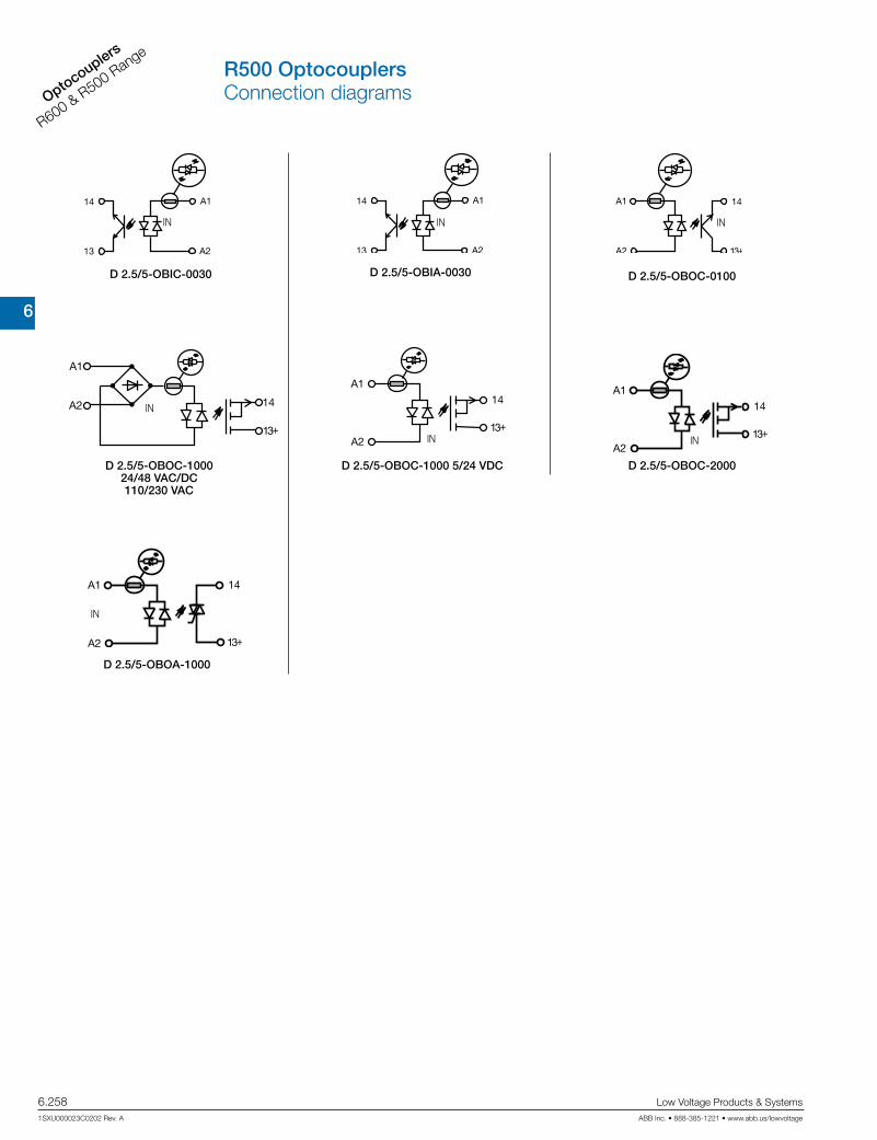
6
Interface re
lays
CR Range
6.258 Low Voltage Products & Systems
1SXU000023C0202 Rev. A ABB Inc. • 888-385-1221 • www.abb.us/lowvoltage
Optocouplers
R600 & R500 Range
D 2.5/5-OBIC-0030
IN
D 2.5/5-OBIA-0030
IN
D 2.5/5-OBOC-0100
IN
D 2.5/5-OBOC-1000 5/24 VDC
IN
IN
D 2.5/5-OBOC-1000 24/48 VAC/DC 110/230 VAC
D 2.5/5-OBOC-2000
IN
D 2.5/5-OBOA-1000
IN
R500 OptocouplersConnection diagrams

6
Interface relays
CR Range
Low Voltage Products & Systems 6.259ABB Inc. • 888-385-1221 • www.abb.us/lowvoltage 1SXU000023C0202 Rev. A
Optocouplers
R600 & R500 Range
Technical data
Pluggable optocoupler : 5 to 58 V DC output / 30 mA - 5.08 mm 0.200“ spacing
D 2.5/5-OBIC-0030
Input
Input voltage 4.5 V to 5.5 VDC 19.2 V to 27.6 VDC 38.4 V to 55.2 VDC 93.5 V to 140 VDC
Input current 6 mA 5 mA 4.1 mA 3 mA
Pull-in voltage at Is=100% 3.5 V 12 V 21 V 50 V
Switching time C / O 20 µs / 1.3 ms
Operating frequency 400 Hz
Permissible leakage current 1 mA 0.8 mA
Output
Output voltage 4.5 to 58 V DC
Output current min. 0.5 mA
Output current max. 30 mA
Output leakage current at Umax. < 50 µA
Residual voltage at I max and U ratedtypical 2.3 V DC
max 2.7 V DC
Frequency on inductive load
Isolation Input / Output input / Output 2500 V RMS
Ambient temperature storage -40...+80 °C
operating See derating curve
Other characteristics
Body material grey UL 94 V0
Wire sizeSolid wire 0.2 - 4 mm² (24-12 AWG)
Stranded wire 0.22 - 2.5 mm² (24-12 AWG)
Rated wire size 2.5 mm² (12 AWG)
Wire stripping length 9 mm (0.354 in)
Recommended screwdriver 3.5 mm (0.137 in)
Protection IP20 NEMA1
Recommended torque 0.4-0.6 Nm (3.5-5.3 lb.in)
Approvals (pending),
Reference standards CEI 947-7-1 / CEI 947-1 / CEI 1131-2 (in relevant parts) / CEI 60664-1 / CEM : IRC 1000-4-2, 3, 4, 5, 6.
D 2.5/5-OBIC-0030
1 : 5 V - 24 V - 48 V 2 : 115 V
Derating curve
14
A2
A113
230 V
115 V24 V
48 V
87 3.42”
104
4.09
”
111,
34.
38”
41,4 1.63”center of rail
Dimensional drawings
R500 OptocouplersTechnical data

6
Interface re
lays
CR Range
6.260 Low Voltage Products & Systems
1SXU000023C0202 Rev. A ABB Inc. • 888-385-1221 • www.abb.us/lowvoltage
Optocouplers
R600 & R500 Range
Technical data
Pluggable optocoupler : 5 to 58 V DC output / 30 mA - 5.08 mm 0.200“ spacing
D 2.5/5-OBIA-0030
Input
Input voltage 20.4 to 26.4 V AC 40.8 V to 52.8 V AC 98 V to 126.5 V AC 195.5 V to 253 V AC
50 / 60 Hz 50 Hz
Input current 8.5 mA 4.5 mA 8 mA 7 mA
Pull-in voltage at Is=100% 13 V 22 V 50 V 95 V
Switching time C / O 6 ms / 10 ms
Operating frequency 30 Hz
Permissible leakage current 1 mA 2 mA
Output
Output voltage 4.5 V to 58 V DC
Output current min. 0.5 mA
Output current max. 30 mA
Output leakage current at Umax. < 50 µA
Redidual voltage at I max and U ratedtypical 2.3 V DC
max 2.7 V DC
Frequency on inductive load 2500 V RMS
Isolation Input / Output input / Output
Temperature
Ambient temperature storage -40...+80 °C
operating See derating curve
Other characteristics
Body material grey UL 94 V0
Wire sizeSolid wire 0.2 - 4 mm² (24-12 AWG)
Stranded wire 0.22 - 2.5 mm² (24-12 AWG)
Rated wire size 2.5 mm² (12 AWG)
Wire stripping length 9 mm (0.354 in)
Recommended screwdriver 3.5 mm (0.137 in)
Protection IP20 NEMA1
Recommended torque 0.4-0.6 Nm (3.5-5.3 lb.in)
Approvals (pending),
Reference standards CEI 947-7-1 / CEI 947-1 / CEI 1131-2 (in relevant parts) / CEI 60664-1 / CEM : IRC 1000-4-2, 3, 4, 5, 6.
D 2,5/5-OBIA-0030
1 : 24 V - 48 V 2 : 115 V - 230 V
Dimensional drawings
14A2
A1
13 230 V
115 V24 V
48 V
87 3.42”
104
4.09
”
111,
34.
38”
41,4 1.63”center of rail
Derating curve
R500 OptocouplersTechnical data

6
Interface relays
CR Range
Low Voltage Products & Systems 6.261ABB Inc. • 888-385-1221 • www.abb.us/lowvoltage 1SXU000023C0202 Rev. A
Optocouplers
R600 & R500 Range
Technical data
Pluggable optocoupler : 5 to 58 V DC output / 100 mA - 5.08 mm 0.200“ spacing
D 2.5/5-OBIA-0100 5 V DC / 24 V DC D 2.5/5-OBIA-0100 48 V DC
Input
Input voltage 4.5 V to 5.5 V DC 20.4 V to 28.8 V DC 40.8 V to 57.6 V DC
Frequency
Input current 8.5 mA 4.8 mA 3.9 mA
Pull-in voltage at Is=100% 2.9 V DC 16 V DC 26 V DC
Switching time C / O 20 µs / 1.3 ms
Operating frequency 400 Hz
Permissible leakage current 1 mA
Output
Output voltage 4.5 V to 58 V DC
Output current min. 1 mA
Output current max. 100 mA
Output leakage current at Umax. < 50 µA
Redidual voltage at I max and U ratedtypical 1 V DC
max 1.3 V DC
Frequency on inductive load See Note 1
Isolation Input / Output input / Output 2500 V RMS
Temperature
Ambient temperature storage -40...+80 °C
operating See derating curve
Other characteristics
Body material grey UL 94 V0
Wire sizeSolid wire 0.2 - 4 mm² (24-12 AWG)
Stranded wire 0.22 - 2.5 mm² (24-12 AWG)
Rated wire size 2.5 mm² (12 AWG)
Wire stripping length 9 mm (0.354 in)
Recommended screwdriver 3.5 mm (0.137 in)
Protection IP20 NEMA1
Recommended torque 0.4-0.6 Nm (3.5-5.3 lb.in)
Approvals (pending),
Reference standards CEI 947-7-1 / CEI 947-1 / CEI 1131-2 (in relevant parts) / CEI 60664-1 / CEM : IRC 1000-4-2, 3, 4, 5, 6.
Dimensional drawings
14A2
A1
13 230 V
115 V24 V
48 V
87 3.42”
104
4.09
”
111,
34.
38”
41,4 1.63”center of railD 2.5/5-OBOC-0100 5 V DC / 24 V DC D 2.5/5-OBOC-0100 48 V DC
LR
Fmax = (1-0,007 x Us) / (L x Is²) Fmax = (1-0,007 x Us) / (P x )
or
Us = Output voltage Is = Output current L = Inductance of load P = Power of load R = Resistance of load
Note 1 :
Derating curve
R500 OptocouplersTechnical data

6
Interface re
lays
CR Range
6.262 Low Voltage Products & Systems
1SXU000023C0202 Rev. A ABB Inc. • 888-385-1221 • www.abb.us/lowvoltage
Optocouplers
R600 & R500 Range
Technical data
Pluggable optocoupler : 5 to 58 V DC output / 1 A - 5.08 mm 0.200“ spacing
D 2.5/5-OBOC-1000
5/24 V DCD 2.5/5-OBOC-1000 24/48 V AC/DC
D 2.5/5-OBOC-1000
110/230 V AC
Input 5 V DC 24 V DC 24 V AC 24 V DC 48 V AC 48 V DC 110 V AC 230 V AC
Input voltage 4.5 - 5.5 V DC
20.4 - 28.8 V DC 24 ± 10 % 20.4 - 28.8
V DC 48 ± 10 % 40.8 to 57.6 V DC 110 ± 10 % 230 ± 10 %
Frequency 50 / 60 Hz 50 / 60 Hz 50 / 60 Hz 50 / 60 Hz
Input current 12.3 mA 6.7 mA 10.5 mA 8 mA 6.8 mA 5.8 mA 8.5 mA 7.5 mA
Pull-in voltage at Is=100% 3.5 V DC 10 V DC
Switching time C / O 20 / 250 µs 50 / 350 µs 15 / 13 ms 5 / 13 ms 15 / 15 ms 6 / 25 ms 15 / 15 ms 15 / 15 ms
Operating frequency 2000 Hz 1500 Hz 20 Hz
Permissible leakage current
Output
Output voltage 4.5 V to 58 V DC
Output current min. 1 mA
Output current max. 1 A
Output leakage current at Umax. < 50 µA
Redidual voltage at I max and U ratedtypical 0.1 V DC
max 0.5 V DC
Frequency on inductive load See Note 1
Isolation Input / Output input / Output 2500 V RMS
Temperature
Ambient temperature storage -40...+80 °C
operating See derating curve
Other characteristics
Body material grey UL 94 V0
Wire sizeSolid wire 0.2 - 4 mm² (24-12 AWG)
Stranded wire 0.22 - 2.5 mm² (24-12 AWG)
Rated wire size 2.5 mm² (12 AWG)
Wire stripping length 10 mm (0.394 in)
Recommended screwdriver 3.5 mm (0.137 in)
Protection IP20 NEMA1
Recommended torque 0.4-0.6 Nm (3.5-5.3 lb.in)
Approvals (pending),
Reference standards CEI 947-7-1 / CEI 947-1 / CEI 1131-2 (in relevant parts) / CEI 60664-1 / CEM : IRC 1000-4-2, 3, 4, 5, 6.
Dimensional drawings
LR
Fmax = (1-0.007 x Us) / (L x Is²)
Fmax = (1-0.007 x Us) / (P x )
or
Us = Output voltageIs = Output currentL = Inductance of loadP = Power of loadR = Resistance of load
Note 1 :
Derating curve
A113+
14
A2 230 V
115 V24 V
48 V
87 3.42”
104
4.09
”
111,
34.
38”
41,4 1.63”center of rail
R500 OptocouplersTechnical data

6
Interface relays
CR Range
Low Voltage Products & Systems 6.263ABB Inc. • 888-385-1221 • www.abb.us/lowvoltage 1SXU000023C0202 Rev. A
Optocouplers
R600 & R500 Range
Technical data
Pluggable optocoupler : 5 to 30 V DC output / 2 A - 5.08 mm 0.200“ spacing
D 2.5/5-OBOC-2000
5/24 V DCD 2.5/5-OBOC-2000 24/48 V AC/DC
D 2.5/5-OBOC-2000
110/230 V AC
Input 5 V DC 24 V DC 24 V AC 24 V DC 48 V AC 48 V DC 110 V AC 230 V AC
Input voltage 4.5 - 5.5 V DC
20.4 - 28.8 V DC 24 ± 10 % 20.4 - 28.8
V DC 48 ± 10 % 40.8 to 57.6 V DC 110 ± 10 % 230 ± 10 %
Frequency 50 / 60 Hz 50 / 60 Hz 50 / 60 Hz 50 / 60 Hz
Input current 12.3 mA 6.7 mA 10.5 mA 8 mA 6.8 mA 5.8 mA 8.5 mA 7.5 mA
Pull-in voltage at Is=100% 3.5 V DC 10 V DC
Switching time C / O 20 / 250 µs 50 / 350 µs 15 / 13 ms 5 / 13 ms 15 / 15 ms 6 / 25 ms 15 / 15 ms 15 / 15 ms
Operating frequency 2000 Hz 1500 Hz 20 Hz
Permissible leakage current
Output
Output voltage 4.5 V to 58 V DC
Output current min. 1 mA
Output current max. 2 A
Output leakage current at Umax. < 50 µA
Redidual voltage at I max and U ratedtypical 0.1 V DC
max 0.5 V DC
Frequency on inductive load See Note 1
Isolation Input / Output input / Output 2500 V RMS
Temperature
Ambient temperature storage -40...+80 °C
operating See derating curve
Other characteristics
Body material grey UL 94 V0
Wire sizeSolid wire 0.2 - 4 mm² (24-12 AWG)
Stranded wire 0.22 - 2.5 mm² (24-12 AWG)
Rated wire size 2.5 mm² (12 AWG)
Wire stripping length 10 mm (0.394 in)
Recommended screwdriver 3.5 mm (0.137 in)
Protection IP20 NEMA1
Recommended torque 0.4-0.6 Nm (3.5-5.3 lb.in)
Approvals (pending),
Reference standards CEI 947-7-1 / CEI 947-1 / CEI 1131-2 (in relevant parts) / CEI 60664-1 / CEM : IRC 1000-4-2, 3, 4, 5, 6.
Dimensional drawings
13+
14
230 V
115 V24 V
48 V
87 3.42”
104
4.09
”
111,
34.
38”
41,4 1.63”center of rail
LR
Fmax = (1-0,012 x Us) / (L x Is²)
Fmax = (1-0,012 x Us) / (P x )
or
Us = Output voltageIs = Output currentL = Inductance of loadP = Power of loadR = Resistance of load
Note 1 :
Derating curve
R500 OptocouplersTechnical data
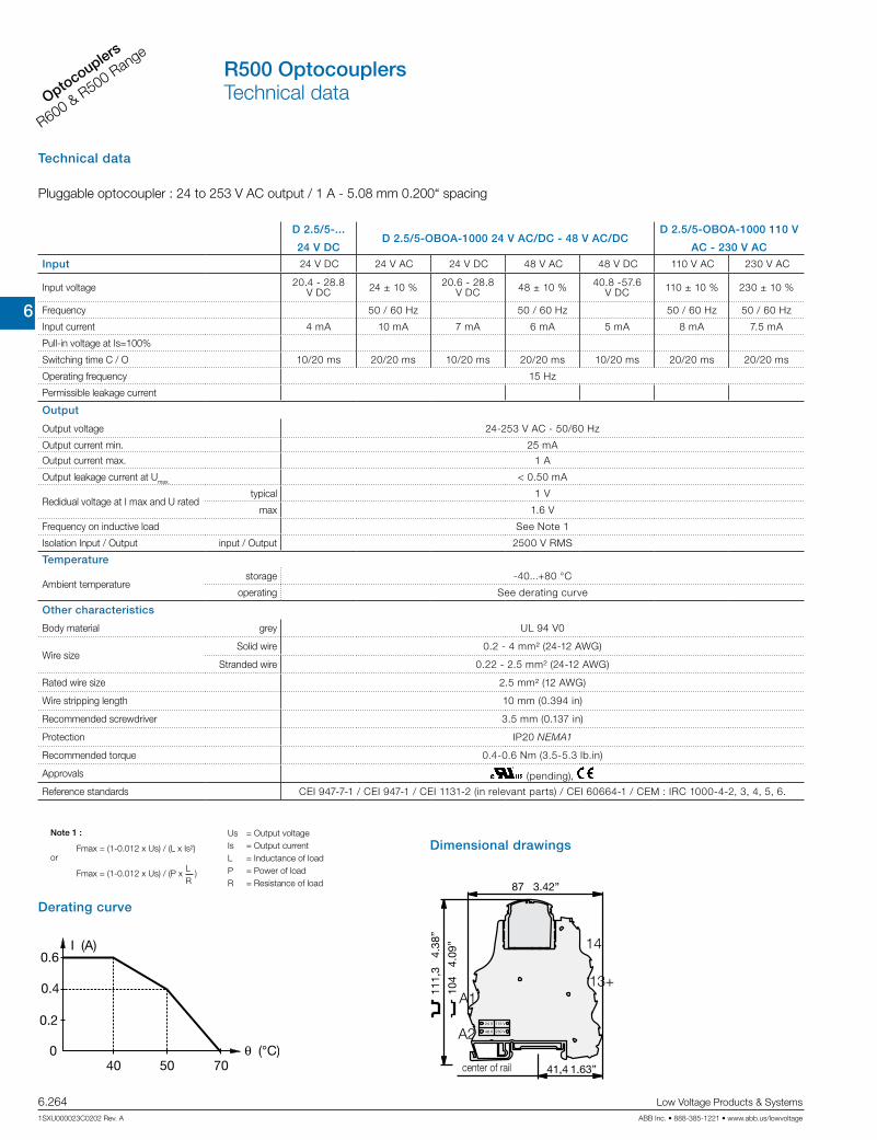
6
Interface re
lays
CR Range
6.264 Low Voltage Products & Systems
1SXU000023C0202 Rev. A ABB Inc. • 888-385-1221 • www.abb.us/lowvoltage
Optocouplers
R600 & R500 Range
Technical data
Pluggable optocoupler : 24 to 253 V AC output / 1 A - 5.08 mm 0.200“ spacing
D 2.5/5-...
24 V DCD 2.5/5-OBOA-1000 24 V AC/DC - 48 V AC/DC
D 2.5/5-OBOA-1000 110 V
AC - 230 V AC
Input 24 V DC 24 V AC 24 V DC 48 V AC 48 V DC 110 V AC 230 V AC
Input voltage 20.4 - 28.8 V DC 24 ± 10 % 20.6 - 28.8
V DC 48 ± 10 % 40.8 -57.6 V DC 110 ± 10 % 230 ± 10 %
Frequency 50 / 60 Hz 50 / 60 Hz 50 / 60 Hz 50 / 60 Hz
Input current 4 mA 10 mA 7 mA 6 mA 5 mA 8 mA 7.5 mA
Pull-in voltage at Is=100%
Switching time C / O 10/20 ms 20/20 ms 10/20 ms 20/20 ms 10/20 ms 20/20 ms 20/20 ms
Operating frequency 15 Hz
Permissible leakage current
Output
Output voltage 24-253 V AC - 50/60 Hz
Output current min. 25 mA
Output current max. 1 A
Output leakage current at Umax. < 0.50 mA
Redidual voltage at I max and U ratedtypical 1 V
max 1.6 V
Frequency on inductive load See Note 1
Isolation Input / Output input / Output 2500 V RMS
Temperature
Ambient temperature storage -40...+80 °C
operating See derating curve
Other characteristics
Body material grey UL 94 V0
Wire sizeSolid wire 0.2 - 4 mm² (24-12 AWG)
Stranded wire 0.22 - 2.5 mm² (24-12 AWG)
Rated wire size 2.5 mm² (12 AWG)
Wire stripping length 10 mm (0.394 in)
Recommended screwdriver 3.5 mm (0.137 in)
Protection IP20 NEMA1
Recommended torque 0.4-0.6 Nm (3.5-5.3 lb.in)
Approvals (pending),
Reference standards CEI 947-7-1 / CEI 947-1 / CEI 1131-2 (in relevant parts) / CEI 60664-1 / CEM : IRC 1000-4-2, 3, 4, 5, 6.
LR
Fmax = (1-0.012 x Us) / (L x Is²)
Fmax = (1-0.012 x Us) / (P x )
or
Us = Output voltageIs = Output currentL = Inductance of loadP = Power of loadR = Resistance of load
Note 1 :
Dimensional drawings
A113+
14
A2 230 V
115 V24 V
48 V
87 3.42”
104
4.09
”
111,
34.
38”
41,4 1.63”center of rail
Derating curve
R500 OptocouplersTechnical data
6
Interface relays
CR Range
Low Voltage Products & Systems 6.265ABB Inc. • 888-385-1221 • www.abb.us/lowvoltage 1SXU000023C0202 Rev. A
Optocouplers
R600 & R500 Range
AccessoriesInterface relays & optocouplers

6
Interface re
lays
CR Range
6.266 Low Voltage Products & Systems
1SXU000023C0202 Rev. A ABB Inc. • 888-385-1221 • www.abb.us/lowvoltage
Optocouplers
R600 & R500 Range
0.2-4 mm² 24-12 AWG 0.22-2.5 mm² 24-12 AWG 320 V 300 V 4 kV 3 6 A 6 A 2.5 mm² 12 AWG 10 mm / .394" 3.5 mm / .137" 0.4-0.6 Nm / 3,5-5,3 lb.in IP 20 / NEMA1
IEC UL/CSA
D 2.5/5-MP
D 2.5/5-MP
1
2
3, 4, 5, 6, 7, 8, 9
10
1
4
5
6
2
3
RC 55R
0.2-4 mm² 24-12 AWG 0.22-2.5 mm² 24-12 AWG 320 V 300 V 4 kV 3 6 A 6 A 2.5 mm² 12 AWG 10 mm / .394" 3.5 mm / .137" 0.4-0.6 Nm / 3.5-5.3 lb.in IP 20 / NEMA1
IEC UL/CSA
D 2.5/5-MP1
D 2.5/5-MP1
DCB (1) FC2 BNMS T5V-1 BNMS T24V-1 BNMS T24V-2 BNMS T48V-1 BNMS T125V-1 BNMS T24V-1 BNMS T48V-1 BNMS T115V-1 BNMS T230V-1
BNMS F125mA-1 BNMS F500mA-1 BNMS F2A-1 BNMS F5A-1 BNMS F125mA-2 BNMS F2A-2 BNMS F5A-2
BNMS F2A-7BNMS ST1 BNMS ST2
PCMS V0 (2)RC 55
0.2-4 mm² 24-12 AWG 0.22-2.5 mm² 24-12 AWG 320 V 300 V 4 kV 3 6 A 6 A 2.5 mm² 12 AWG 10 mm / .394" 3.5 mm / .137" 0.4-0.6 Nm / 3.5-5.3 lb.in IP 20 / NEMA1
IEC UL/CSA
D 2.5/5-MP-24VDC
D 2.5/5-MP-24VAC/DC
D 2.5/5-MP-48VAC/DC
D 2.5/5-MP-110VAC
D 2.5/5-MP-230VAC
D 2.5/5-MP...
DCB (1) FC2 BNMS R24V-1 BNMS R24V-2 BNMS N24V-3 BNMS P24V-3 BNMS N24V-1 BNMS P24V-1 BNMS N24V-2 BNMS P24V-2 BNMS A24V-4
BNMS F125mA-1 BNMS F500mA-1 BNMS F2A-1 BNMS F5A-1 BNMS F125mA-2 BNMS F2A-2 BNMS F5A-2 BNMS F125mA-3 BNMS F125mA-4
BNMS ST1
PCMS V0 (2)RC 55
1
4
5
6
2
3
1
4
5
6
2
3
Ref. Code Catalog No.
Characteristics
RatedRated / GaugeWire size
Current
Wire size
Accessories
Compression Solid wire clamp Stranded wire RatedPulsePollution degree
Voltage
Grey V0
Wire stripping lengthRecommended screwdriverRecommended torqueProtection
ObservationsTerminal blocks are delivered without plugs.
Max. working temperature version without LED : 100°C version with LED : 85°CContact resistance : < 5 mΩ
Spacing 5.08 mm (.200")
blue
DIA. 2
beige
beige
red
red
red
red
red
red
black
red
red
red
red
red
red
red
red
grey
grey
grey
grey
grey
grey
grey
grey
grey
grey
grey
grey
grey
grey
grey
pending
(1) Solely on the top stage. (2) Comb type jumper bar from 2 to 22 poles, see accessories.
center of rail
Order plugs separately
Terminal blocks component holderBase for pluggable plug R500 Series
DIN 3
End stop th. 9 mm BADL V0 039990302End stop th. 9 mm BAM2 V0 039996701Rail 35 x 7.5 x 1 PR30 017322005Rail 35 x 15 x 2.3 PR4 016850012Rail 35 x 15 x 1.5 PR5 016870022
Ref. Code Catalog No.
Grey V0
Spacing 5.08 mm (.200")
pending
blue
DIA. 2
white
white
white
white
white
yellow
yellow
yellow
yellow
grey
grey
grey
grey
grey
grey
grey
grey
grey
grey
Order plugs separately
Ref. Code Catalog No.
Grey V0
Spacing 5.08 mm (.200")
pending
blue
DIA. 2
beige
beige
red
red
red
red
red
red
black
grey
grey
grey
grey
grey
grey
grey
grey
grey
grey
Order plugs separately
Relay/opto. base without output LED Relay/opto. base without input LED Relay/opto. base with output LED
center of rail center of rail
1SNA607224R0100
0105028210007865261SNA031820R1400 1SNA031847R1300
1SNA031807R1400 1SNA031810R1200 1SNA031813R0100 1SNA031815R0300 1SNA031817R0500 1SNA031819R1700 003183913 1SNA031806R1300 1SNA031809R2600 1SNA031808R2500 1SNA031811R0700 1SNA031812R0000 1SNA031814R0200 1SNA031816R0400 1SNA031818R1600 003182101 003183812 003182202 003182303 1SNA031824R0400 003182505 1SNA031826R0600 003182707 003182810 1SNA031849R2500 003182911 003183016 1SNA031832R0400 1SNA031832R0400 1SNA031833R0500 1SNA031833R0500 1SNA205523R2200
1SNA607223R0000
010502821000786526 003183103 1SNA031848R2400 003180021 1SNA031801R1600 1SNA031845R1100 003180217 1SNA031803R1000 003180411 1SNA031805R1200
003182101 003183812 003182202 003182303 1SNA031824R0400 003182505 1SNA031826R0600 1SNA031849R2500 003182911 003183016
1SNA205523R2200
1SNA607222R0700
1SNA607260R2100
1SNA607261R1600
1SNA607266R1300
1SNA607267R1400
1SNA105028R21001SNA007865R26001SNA031820R1400 1SNA031847R1300 1SNA031807R1400 1SNA031810R1200 1SNA031813R0100 1SNA031815R0300 1SNA031817R0500 1SNA031819R1700 003183913
003182101 003183812 003182202 003182303 1SNA031824R0400 003182505 1SNA031826R06001SNA031827R0700 1SNA031828R1000 003182911
1SNA205523R2200
Ref. Code Catalog No. Ref. Code Catalog No. Ref. Code Catalog No.DCB (1) FC2 BNMS R24V-1 BNMS R24V-2
BNMS N24V-3 BNMS P24V-3 BNMS N24V-1 BNMS P24V-1 BNMS N24V-2 BNMS P24V-2 BNMS A24V-4 BNMS N5V-3 BNMS P5V-3 BNMS N48V-3 BNMS P48V-3 BNMS N5V-1 BNMS P5V-1 BNMS N5V-2 BNMS P5V-2 BNMS F125mA-1 BNMS F500mA-1 BNMS F2A-1 BNMS F5A-1 BNMS F125mA-2 BNMS F2A-2 BNMS F5A-2 BNMS F125mA-3 BNMS F125mA-4BNMS F2A-7 BNMS ST1 BNMS ST2 BNMS CAI/U-500 BNMS CAI/U-500 BNMS CAI/U-250 BNMS CAI/U-250 PCMS V0 (2)
1 Test device 2 Test plug 3 Relay plug 1 SPDT 10 mA/6 A 1 SPDT 1 mA/6 A 4 Input optocoupler plug 5 V DC 24 V DC 24 V DC 48 V DC 125 V DC 24 V AC 48 V AC 115 V AC 230 V AC 5 Output optocoupler 24 V DC/100 mA plug 24 V DC/100 mA 24 V DC/2 A 24 V DC/2 A 24 V DC/1 A 24 V DC/1 A 24 V DC/1 A 5 Output optocoupler 5 V DC/100 mA plug 5 V DC/100 mA 48 V DC/100 mA 48 V DC/100 mA 5 V DC/2 A 5 V DC/2 A 5 V DC/1 A 5 V DC/1 A 7 Fuse plug 125 V/125 mA 125 V/500 mA 125 V/2 A 125 V/5 A 250 V/125 mA 250 V/2 A 250 V/5 A 125 V/125 mA 250 V/125 mA 125 V/2 A 8 Strap plug
9 Converter plug 0-20 mA/0-10 V 4-20 mA/2-10 V 0-20 mA/0-5 V 4-20 mA/1-5 V 10 Comb type jumper bar 10 poles R See section on marking

6
Interface relays
CR Range
Low Voltage Products & Systems 6.267ABB Inc. • 888-385-1221 • www.abb.us/lowvoltage 1SXU000023C0202 Rev. A
Optocouplers
R600 & R500 Range
BNMS T5V-1 BNMS T24V-1 BNMS T48V-1
BNMS T24V-1 BNMS T48V-1 BNMS T115V-1
5 V DC 24 V DC 48 V DC
24 V AC 48 V AC 115 V AC 230 V AC
BNMS T230V-1
125 V DC
BNMS T125V-1
432 1 432 1
BNMS T24V-2
BNMS T24V-1 BNMS T24V-2 19.2 V to 27.6 V DC 5 mA 12 V DC 20 µs / 1.3 ms 10 µs / see curve 1 1 mA 58 V / 30 mA 58 V / 5 mA 2.3 V DC 0.3 V DC 2.7 V DC 0.5 V DC TTL 2.5 kV
- 30°C to + 80°C -20°C to + 55°C
Characteristics
Catalog number Ref. Code Cat. No. Ref. Code Cat. No.
Ref. Code Cat. No.
Ref. Code Cat. No.
Input optocoupler plugs
INPUTVoltageMax. currentTypical triggering threshold at Is = 100%Switching time C/OLeakage current
OUTPUTMax. voltage. / Max. currentResidual voltage max. I and rated U standard max. Compatibility Input / Output isolation
TEMPERATURE Storage Operating
Characteristics
Part number Ref. Code Cat. No. Ref. Code Cat. No.Ref. Code Cat. No.
INPUTVoltageMax. currentTypical triggering threshold at Is = 100%Switching time C/OLeakage current
OUTPUTMax. voltage / Max. currentResidual voltage max. I and rated U standard max. Input / Output isolation
TEMPERATURE Storage Operating
4.5 V to 5.5 V DC 6 mA 3.5 V 20 µs / 1.3 ms 58 V / 30 mA 2.3 V DC 2.7 V DC 2.5 kV - 30°C to + 80°C - 20°C to + 55°C
38.4 V to 55.2 V DC 4.1 mA 21 V DC 20 µs / 1.3 ms 0,8 mA 58 V / 30 mA 2.3 V DC 2.7 V DC 2.5 kV - 30°C to + 80°C - 20°C to + 55°C
20.4 V to 26.4 V AC 8.5 mA 13 V AC 6 ms / 10 ms 1 mA 58 V / 30 mA 2.3 V DC 2.7 V DC 2.5 kV - 30°C to + 80°C - 20°C to + 55°C
40.8 V to 52.8 V AC 4.5 mA 22 V AC 6 ms / 10 ms 1 mA 58 V / 30 mA 2.3 V 2.7 V 2.5 kV - 30°C to + 80°C - 20°C to + 55°C
98 V to 126.5 V AC 8 mA 50 V AC 6 ms / 10 ms 2 mA 58 V / 30 mA 2.3 V 2.7 V 2.5 kV - 30°C to + 80°C - 20°C to + 55°C
195.5 V to 253 V AC 7 mA 95 V AC 6 ms / 10 ms 2 mA 58 V / 30 mA 2.3 V 2.7 V 2.5 kV - 30°C to + 80°C - 20°C to + 55°C
Derating curveDerating curve
Ref. Code Cat. No.
93.5 V to 140 V DC 3 mA 50 V DC 20 µs / 1.3 ms 58 V / 30 mA 2.3 V DC 2.7 V DC 2.5 kV - 30°C to + 80°C - 20°C to + 55°C
DC plugs AC plugs Switching time RL curve 1for 24 V DC plugs only
Sw
itchi
ng ti
me
(µs)
Load resistance RL (kΩ)
1SNA031831R0300
1SNA031800R2100
1SNA031801R1600
1SNA031802R1700
1SNA031803R1000
1SNA031804R1100
1SNA031805R1200
1SNA031845R1100
1SNA031848R2400

6
Interface re
lays
CR Range
6.268 Low Voltage Products & Systems
1SXU000023C0202 Rev. A ABB Inc. • 888-385-1221 • www.abb.us/lowvoltage
Optocouplers
R600 & R500 Range
BNMS N5V-3 BNMS N24V-3 BNMS N48V-3
BNMS N5V-2 BNMS N24V-2
N5V-3 P5V-3
BNMS P5V-3
N24V-3 P24V-3
BNMS P24V-3
N48V-3 P48V-3
BNMS P48V-3
N5V-2 P5V-2
BNMS P5V-2
N24V-2 P24V-2
I (mA)
(°C )0
100
57 60
I (mA)
(°C )0
100
57 60
I (mA)
(°C )0
100
57 60
432 1 432 1 432 1 432 1 432 1 432 1
432 1 432 1 432 1 432 1
Characteristics
Transistor output optocoupler plugs
Ref. Code Cat. No. Ref. Code Cat. No. Type Cat. No.Part numbers
Characteristics
MOS output optocoupler plugs
Ref. Code Cat. No. Ref. Code Cat. No.Part numbers
100 mA output optocoupler 24 V DC
1 A output optocoupler 5 V DC
1 A output optocoupler 24 V DC
INPUTVoltageMax. currentTypical triggering threshold at Is=100%Switching time C/OLeakage current
OUTPUTMax. voltage / Max. currentResidual voltage max. I and rated U standard U max.Freuency on inductive loadInput / Output isolation
TEMPERATURE Storage Operating
100 mA output optocoupler 5 V DC
100 mA output optocoupler 48 V DC
4.5 V to 5.5 V DC 12.5 mA 3.5 V DC 20 µs / 250 µs 1 mA
58 V / See graphs 1 V DC 1.3 V DC See Note 1 2,5 kV
- 30°C to + 80°C - 20°C to + 60°C
20.4 V to 28.8 V DC 6.7 mA 10 V DC 50 µs / 350 µs 1 mA
58 V / See graphs
1 V DC 1.3 V DC See Note 1 2.5 kV
- 30°C to + 80°C - 20°C to + 60°C
Note 1 :
Fmax = (1-0,007 x Us) / (L x Is²)orFmax = (1-0,007 x Us) / (P x )
Us = Output voltage supplyIs = Output currentL = Inductive loadP = Load powerR = Load resistance
LR
INPUTVoltageMax. currentTypical triggering threshold at Is = 100 %Switching time C/OLeakage current
OUTPUTMax. voltage / Max. currentResidual voltage max. I and rated U standard U max.Freuency on inductive loadInput / Output isolation
TEMPERATURE Storage Operating
4.5 V to 5.5 V DC 8.5 mA 2.9 V DC 20 µs / 1.3 ms 1 mA
58 V / 100 mA 1 V DC 1.3 V DC See Note 1 2,5 kV
- 30°C to + 80°C - 20°C to + 60°C
20.4 V to 28.8 V DC 4.8 mA 16 V DC 20 µs / 1.3 ms 1 mA
58 V / 100 mA 1 V DC 1.3 V DC See Note 1 2,5 kV
- 30°C to + 80°C - 20°C to + 60°C
40.8 V to 57.6 V DC 3.9 mA 26 V DC 20 µs / 1.3 ms 1 mA
58 V / 100 mA 1 V DC 1.3 V DC See Note 1 2,5 kV
- 30°C to + 80°C - 20°C to + 60°C
Derating curve Derating curveDerating curve
Derating curve Derating curve
1SNA031806R1300 1SNA031807R1400 1SNA031808R2500
1SNA031816R0400 1SNA031817R0500
1SNA031809R2600 1SNA031810R1200 1SNA031811R0700
1SNA031818R1600

6
Interface relays
CR Range
Low Voltage Products & Systems 6.269ABB Inc. • 888-385-1221 • www.abb.us/lowvoltage 1SXU000023C0202 Rev. A
Optocouplers
R600 & R500 Range
BNMS N5V-1 BNMS N24V-1
BNMS A24V-4
N5V-1 P5V-1
BNMS P5V-1
N24V-1 P24V-1
BNMS P24V-1
432 1
432 1 432 1 432 1 432 1
Characteristics
MOS output optocoupler plug
Ref. Code Cat. No. Ref. Code Cat. No.Part numbers
Characteristics
Triac output optocoupler plug
Ref. Code Cat. No.Part numbers
2 A output optocoupler 24 V DC
2 A output optocoupler 5 V DC
4.5 V to 5.5 V DC 12.5 mA 3.5 V DC 20 µs / 250 µs 1 mA
30 V DC / See graphs 1 V DC 1.3 V DC See Note 2 2.5 kV
- 30°C to + 80°C - 20°C to + 60°C
20.4 V to 28.8 V DC 6.7 mA 10 V DC 50 µs / 350 µs 1 mA
30 V / See graphs 1 V DC 1.3 V DC See Note 2 2.5 kV
- 30°C to + 80°C - 20°C to + 60°C
Note 2 :
Fmax = (1 - 0.012 x Us) / (L x Is²)orFmax = (1 - 0.012 x Us) / (P x )
Us = Output voltage supplyIs = Output currentL = Inductive loadP = Load powerR = Load resistance
LR
Derating curve Derating curve
INPUTVoltageMax. currentTypical triggering thresholdSwitching time C/OLeakage current
OUTPUTMax. voltage / Max. currentResidual voltage max. I and rated U standard U max.Input / Output isolation
TEMPERATURE Storage Operating
20.4 V to 28.8 V DC 3.8 mA 10 V DC 9.5 ms / 12 ms
24 V to 253 V AC / See derating curve 1 V AC 1.3 V AC 2,5 kV
- 30°C to + 80°C - 20°C to + 70°C
1 A output optocoupler 24 V DC
Derating curve
1SNA031812R0000 003181301 003181402 003181503
003183913
INPUTVoltageMax. currentTypical triggering thresholdSwitching time C/OLeakage current
OUTPUTMax. voltage / Max. currentResidual voltage max. I and rated U standard U max.Freuency on inductive loadInput / Output isolation
TEMPERATURE Storage Operating
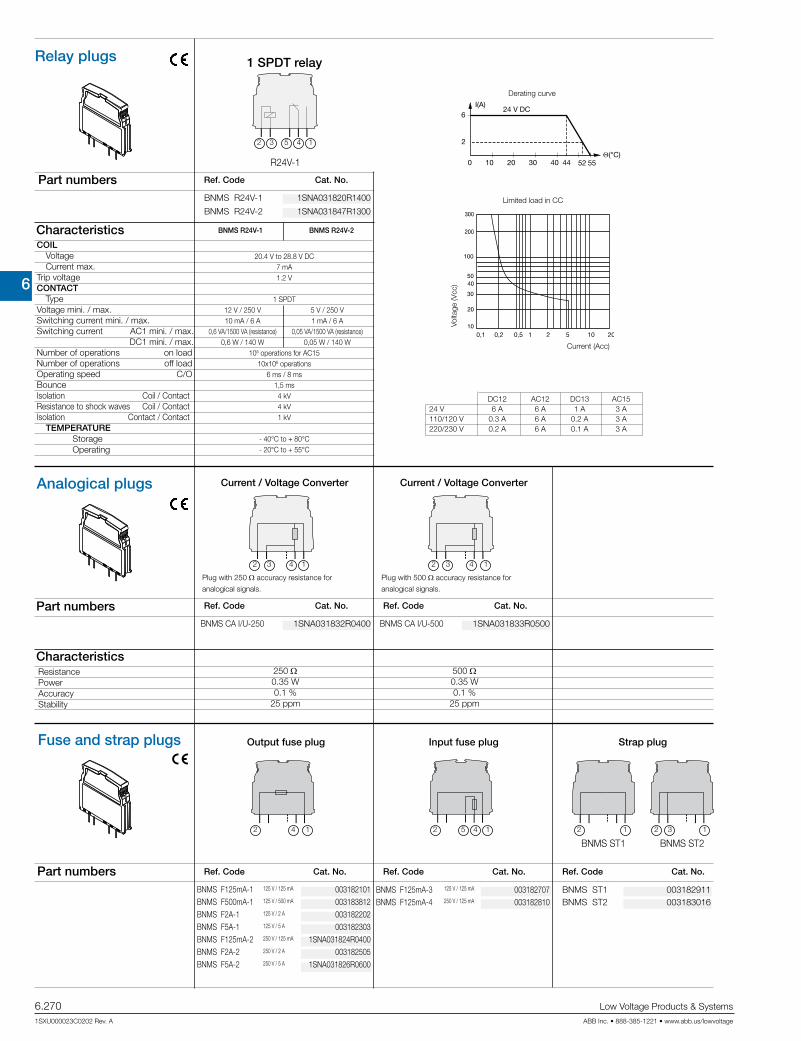
6
Interface re
lays
CR Range
6.270 Low Voltage Products & Systems
1SXU000023C0202 Rev. A ABB Inc. • 888-385-1221 • www.abb.us/lowvoltage
Optocouplers
R600 & R500 Range
BNMS F125mA-1BNMS F500mA-1BNMS F2A-1BNMS F5A-1BNMS F125mA-2BNMS F2A-2BNMS F5A-2
BNMS F125mA-3BNMS F125mA-4
BNMS ST1BNMS ST2
BNMS ST1 BNMS ST2
125 V / 125 mA
125 V / 500 mA
125 V / 2 A
125 V / 5 A
250 V / 125 mA
250 V / 2 A
250 V / 5 A
125 V / 125 mA
250 V / 125 mA
42 1 5 12 4 12 12 3
BNMS R24V-1
R24V-1
624 V DC
2
I(A)
Θ(°C)0 10 20 30 40 44 52 55
DC12 AC12 DC13 AC1524 V 6 A 6 A 1 A 3 A110/120 V 0.3 A 6 A 0.2 A 3 A220/230 V 0.2 A 6 A 0.1 A 3 A
BNMS CA I/U-250
250 Ω 0.35 W 0.1 % 25 ppm
BNMS CA I/U-500
500 Ω 0.35 W 0.1 % 25 ppm
1432 5
432 1 432 1
BNMS R24V-2
BNMS R24V-1 BNMS R24V-2
Fuse and strap plugs
Ref. Code Cat. No. Ref. Code Cat. No. Ref. Code Cat. No.Part numbers
Output fuse plug Input fuse plug Strap plug
Characteristics
Part numbers
Characteristics
Relay plugs
Ref. Code Cat. No.
Part numbers
1 SPDT relay
Limited load in CC
Current (Acc)
Volta
ge (V
cc)
Derating curve
COILVoltageCurrent max.
Trip voltageCONTACT
TypeVoltage mini. / max.Switching current mini. / max.Switching current AC1 mini. / max. DC1 mini. / max.Number of operations on load Number of operations off load Operating speed C/OBounce Isolation Coil / ContactResistance to shock waves Coil / ContactIsolation Contact / Contact
TEMPERATURE Storage Operating
Analogical plugs
Ref. Code Cat. No.
ResistancePowerAccuracyStability
Ref. Code Cat. No.
Current / Voltage Converter
Plug with 250 Ωaccuracy resistance for
analogical signals.
Current / Voltage Converter
Plug with 500 Ωaccuracy resistance for
analogical signals.
20.4 V to 28.8 V DC 7 mA 1.2 V
1 SPDT 12 V / 250 V 5 V / 250 V 10 mA / 6 A 1 mA / 6 A 0,6 VA/1500 VA (resistance) 0,05 VA/1500 VA (resistance) 0,6 W / 140 W 0,05 W / 140 W 105 operations for AC15 10x106 operations 6 ms / 8 ms 1,5 ms 4 kV 4 kV 1 kV
- 40°C to + 80°C - 20°C to + 55°C
003182101 003183812 003182202 003182303 1SNA031824R0400 003182505 1SNA031826R0600
003182707 003182810
003182911 003183016
1SNA031820R1400
1SNA031832R0400 1SNA031833R0500
1SNA031847R1300

6
Interface relays
CR Range
Low Voltage Products & Systems 6.271ABB Inc. • 888-385-1221 • www.abb.us/lowvoltage 1SXU000023C0202 Rev. A
Optocouplers
R600 & R500 RangeBADL
BADL 9 mm 50 BAM2 10 mm 50 BAM2 10 mm 50 BAM2 10 mm 50 BAMH 9.1 mm 50 BAMH 9.1 mm 50 BADH 12 mm 50
BAM2
BAMH
BADH
PR30 PR3.Z2
PR5
PR4
FC2 FC2 10
BJ612-10 10
BJ612-...
SC612 10SC612
D4/12-3-3 5 D4/12-3R-3R 5
D4/12-3...
2.5 mm²
4 mm²
4 mm²
4 mm²
BJ612-...
BJ612-...
2.5 mm²
End stops
Description Ref. Code Catalog number Packaging Weight kg
End stop DIN 3 grey End stop with screws DIN 3 light grey grey beige High end stop with screws DIN 1 and DIN 3 grey beige High end stop with screws DIN 3 grey
The end stops are mounted at the extremity of the terminal board assembly, giving additional support to the terminal blocks as markers. For various types of marking, refer to the marker section.
Mounting railsSymmetrical white passivated galvanized steel prepunched rail PR30 2 m 017322005 1
Symmetrical white passivated galvanized PR3.Z2 2 m 017430017 1 steel rail Symmetrical white passivated galvanized PR5 2 m 016870022 1 steel rail Symmetrical white passivated galvanized PR4 2 m 016850012 1 steel rail
Test devicesTest plug DIA. 2 mm
Assembled jumper bar 10 poles - 24 A
Assembled jumper barThis accessory permits electrical connection between 2 to 70 blocks with 6 mm spacing placed side by side. It can be used with screw clamp or spring clamp blocks with 6 mm or 12 mm spacing.Interconnection of blocks not placed side by side is possible if teeth of the jumper bar have been cut in front of the blocks not to be connected. These teeth can be removed using pliers.Use of separator end sections before and after the jumper bar is reuired to preserve IP20 protection of the assembly.
Separator end section
Separator end sectionDirectly mounted on the rail beside the block, it permits to identify and make electrical insulation of product groups using jumper bars. Dimensions are the same as screw clamp blocks : width 70 mm and height on rail 67.5 mm with 2 mm spacing.
Screw clamp distribution block sp. 12 mm Spring clamp distribution block sp. 12 mm
Distribution module This terminal block with BJ612-... jumper bars permits 2 polarities distribution (PCL side and process side) thanks to two separate circuits, each of them including : - one 4 mm² input, - two 2,5 mm² outputs - one double output for jumper bar BJ612-...
It permits also the connection of ground to the rail though a 4 mm² input.
Rated voltage : 250 VAC-DC Rated current : 32 A (4 mm²) - 16 A (2,5 mm²) Recommended torue : 0.4 - 0.6 Nm
039990302 039995701 020635116 029635100 011483600 019483601 011690027
1SNA007865R2600
029048801
1SNA290474R0200
1SNA645031R2000 1SNA645531R2200

6
Interface re
lays
CR Range
6.272 Low Voltage Products & Systems
1SXU000023C0202 Rev. A ABB Inc. • 888-385-1221 • www.abb.us/lowvoltage
Optocouplers
R600 & R500 Range
2 3 4 5 6 7 8 9 10 11 12 13 14 15 16 17 18 19 20 21 22
PCMS
DC
DCB
PC EIP
PC
011355024EIP
PC9 15 A 10 poles
BJS
BJ
EV6D
-55°C -> +110°C IP20 / NEMA1
600 600 26 15 2.5 mm2 14 AWG
2.5 mm² 14 AWG 2.5 mm²
IEC CSA NFC VDE
4
2
1
3
1
43
2
AD 2,5
Accessories
Comb-type jumperThis accessory permits the electrical connection of 2 to 22 blocks.
No. Grey Red Blue Green/Yellow of UL94V0 UL94V0 UL94V0 UL94V0 poles
This patented device is mounted on the round screwdriver opening. It is used for trouble shooting, measuring and control for monitoring and repairing an installation, on blocks without a test socket. For this, the device receives an FC2 test plug.
The DC's are differentiated by their colour :
blue for MA 2.5/5 blocks
Test device on screw head
Comb-type jumper bar
This accessory can be used only on the terminal blocks with at least one compression clamp connection. It permits the electrical connec-tion of 2 to 10 blocks.Interconnection of non-consecutive blocks is possible by removing the teeth opposite the blocks which must not be connected. The comb-type jumper bars can be cut using pliers (or a saw) : in this case, the use of an insulating tip EIP is recommended. The comb is placed in the compression clamp before tightening the screws, above the eventual conductor.
To be mounted on blocks series R900 and R910 :
Insulating tip for comb
Comb-type jumper bar
Subassemblyscrew + washer + post
Jumper bar not assembled
Jumper bar
To connect terminal blocks, place the metal tube into the top center hole on each terminal block to be connected.The metal tube contacts the terminal block's internal connector bar.
To be mounted on blocks series R910 :
Screw + washer + post
Characteristics
Wire size mm² / AWG
Voltage V Current ARated wire size mm² / AWGWorking temperature °CProtection
Rigid
Flexible
IDC jumper(insulation displacement jumper)
Quick-jump lets you interconnect screw clamp terminals of different sizes, levels and all manufacturers uickly and safely. Its insulation displacement technology makes it easy to use, fast, economical and does not reuire a special tool. Use as a jumper between relays, switches and other electronic components. ABB Quick-jump will fit any screw clamp type terminal block, from 6 mm .238" spacing and larger.
Adding a shunt in an installation :
1 - Insert ABB Quick-jump into your terminal screw clamp.2 - Guide the terminal screw clamp into contact with the wire.3 - Secure the wire by closing the Quick-jump lever with any flat nose
pliers.4 - Tighten the terminal screw.
How to use : connecting Quick-jump to your terminal
1 - Insert ABB Quick-jump into your terminal screw clamp.2 - Tighten the terminal screw.3 - Guide jumper wire through the V-shaped opening in the Quick-jump.4 - Secure the wire by closing the Quick-jump lever with any flat nose pliers.
Insulation displacement jumper
1SNA205491R2300 1SNA205492R2400 1SNA205493R2500 – 1SNA205495R2700 – – – 1SNA205499R0300 1SNA205500R1000 1SNA205501R0500 – 1SNA205503R0700 1SNA205504R0000 1SNA205505R0100 – 1SNA205507R0300 1SNA205508R1400 1SNA205509R1500 – 1SNA205511R2600 – – – 1SNA205515R2200 – – – 1SNA205519R0600 – – – 1SNA205523R2200 1SNA205524R2300 1SNA205525R2400 1SNA205526R2500 1SNA205527R2600 – – – 1SNA205531R2200 1SNA205532R2300 1SNA205533R2400 1SNA205534R2500 1SNA205535R2600 – – – 1SNA205539R0200 – – – 1SNA205543R0600 – – – 1SNA205547R0200 1SNA205548R1300 1SNA205549R1400 1SNA205550R1100 1SNA205551R0600 – – – 1SNA205555R0200 – – – 1SNA205559R1600 – – – 1SNA205563R0200 1SNA205564R0300 1SNA205565R0400 1SNA205566R0500 1SNA205567R0600 – – – 1SNA205571R0200 – – –
010502821
1SNA168400R1600
011420520
021016012
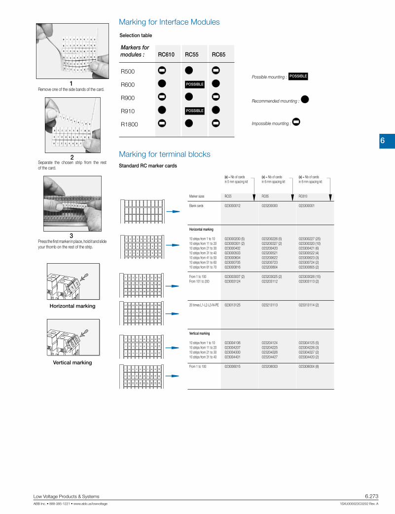
6
Interface relays
CR Range
Low Voltage Products & Systems 6.273ABB Inc. • 888-385-1221 • www.abb.us/lowvoltage 1SXU000023C0202 Rev. A
Optocouplers
R600 & R500 Range
1
2
3
Marking for Interface Modules
Selection table
Remove one of the side bands of the card.
Separate the chosen strip from the rest of the card.
Press the first marker in place, hold it and slide your thomb on the rest of the strip.
Possible mounting : POSSIBLE
Recommended mounting :
Impossible mounting :
Horizontal marking
Vertical marking
Marking for terminal blocksStandard RC marker cards
Marker sizes RC55 RC65 RC610
Blank cards
Horizontal marking 10 strips from 1 to 10 10 strips from 11 to 20 10 strips from 21 to 30 10 strips from 31 to 40 10 strips from 41 to 50 10 strips from 51 to 60 10 strips from 61 to 70
From 1 to 100 From 101 to 200
20 times L1-L2-L3-N-PE
Vertical marking 10 strips from 1 to 10 10 strips from 11 to 20 10 strips from 21 to 30 10 strips from 31 to 40
From 1 to 100
(x) = Nb of cards (x) = Nb of cards (x) = Nb of cards in 5 mm spacing kit in 6 mm spacing kit in 6 mm spacing kit
Markers for modules : RC610 RC55 RC65
R500
R600 POSSIBLE
R900
R910 POSSIBLE
R1800
023000012 023200000 023300001
023000200 (5) 023200226 (5) 023300227 (25) 023000301 (2) 023200327 (2) 023300320 (10) 023000402 023200420 023300421 (6) 023000503 023200521 023300522 (4) 023000604 023200622 023300623 (3) 023000705 023200723 023300724 (2) 023000816 023200804 023300805 (2) 023003007 (2) 023203025 (2) 023303026 (15) 023003124 023203112 023303113 (2)
023013125 023213113 023313114 (2)
023004106 023204124 023304125 (5) 023004207 023204225 023304226 (3) 023004300 023204326 023304327 (2) 023004401 023204427 023304420 (2)
023006015 023206003 023306004 (8)
6
Interface re
lays
CR Range
6.274 Low Voltage Products & Systems
1SXU000023C0202 Rev. A ABB Inc. • 888-385-1221 • www.abb.us/lowvoltage
Optocouplers
R600 & R500 RangeNotes

6
CL RangeLogic relays
Low Voltage Products & Systems 6.275ABB Inc. • 888-385-1221 • www.abb.us/lowvoltage 1SXU000023C0202 Rev. A
Logic relays
Logi
c re
lays

6
CL Range
Logic relays
6.276 Low Voltage Products & Systems
1SXU000023C0202 Rev. A ABB Inc. • 888-385-1221 • www.abb.us/lowvoltage
S1 K1 S4
S5
K1 K2 T1
T1
T1
S6
Documentation (download from the internet)Logic relay manual 1SVC 440 795 M0100Remote display manual 1SVC 440 795 M2100Display system manual 1SVC 440 795 M1100
ConceptCL range logic relays are suitable for small and medium-sized control tasks and are able to substitute logic wiring in a quick and simple manner.They can be used for applications in control as well as for timing functions, e. g. • in buildings, lighting systems, air-conditioning systems, general control
functions,• in small machines and systems or• as stand-alone control module for small applications.
Steps to the application of CL range• CL range can be used easily, rapidly and comfortably without any time-
consuming planning and programming.• The user can discover the advantages and the benefit of these logic re-
lays in no time at all.• CL range provides for the control statements according to a simple cir-
cuit diagram.• Setup, storage, simulation and documentation are performed using the
compact and user-friendly CL-SOFT software (CL-LAS.PS002).
Software characteristics (CL-SOFT)• display on a PC monitor according to IEC, ANSI• different languages to choose from• easy installation on all Microsoft WindowsTM operating systems
Logic links instead of wiring
Technical Data overview
Logic relays• 8 or 12 digital inputs • 4 or 6 digital relay outputs• optionally with 4 or 8 transistor outputs• 128 rungs• 3 contacts as n/o or n/c contacts in series plus 1 coil per rung• optionally with 2 or 4 analog inputs (not 100-240 V AC version)• power flow display for checking the circuit diagram (devices with display)• expansions for local or remote level• enclosure color RAL 7035• DIN rail mounting
Display system• usable as compact HMI logic relay• fully graphic, backlit display module• 12 digital inputs• 4 digital relay outputs• optionally with 4 transistor outputs• 256 rungs• 4 contacts as n/o or n/c contacts in series plus 1 coil per rung• optionally with 4 analog inputs (not 100-240 V AC version)• networking-compatible via CL-NET• front panel mounting• expansion for local
Remote display• Remote display up to a distance of 5 m• Illustration of text and status displays• Remote adjustment via keypad• Front panel mounting
Software• 16 timing relays 0.01-99:59 h• 16 counting relays for up-, down counting• 8 weekly timer, 8 annual timers• 16 analog value comparators• 16 freely editable display texts• 32 markers or auxiliary relays
Logic relaysSystem overview

6
CL RangeLogic relays
Low Voltage Products & Systems 6.277ABB Inc. • 888-385-1221 • www.abb.us/lowvoltage 1SXU000023C0202 Rev. A
Power
98a
8b
3
4
6, 8b
5
71b1a
2 2
6, 8b
5
98a
8b
Power
1a Logic relay CL-LS..1b Expandable logic relay CL-LM..2 Power supply CP-D...3 I/O expansion CL-LER.., CL-LET.. for logic relays CL-LM..4 Coupler unit CL-LEC.. for remote expansion of logic relays CL-LM..5 Memory module CL-LAS.MD003 for logic relays CL-LS.., CL-LM..6 Connecting cable CL-LAS.TK001, CL-LAS.TK002 to connect PC7 CL-LINK plug CL-LAS.TK011 to connect expansion to logic relays CL-LM..8a Remote display connection module CL-LDC.S..8b Connecting cable CL-LAD.TK007 to connect a remote displays to a logic relay9 Display module CL-LDD..
Logic relays
Stand alone Expandable
2b
1
3
2a
5
4
Expansion of logic relays*
1 Logic relay CL-LM..2 I/O expansion CL-LER.., CL-LET.. 2a local expansion 2b remote expansion3 Coupler unit CL-LEC.. for remote expansion of logic relays CL-LM..4 CL-LINK plug CL-LAS.TK011 for expansion of logic relays CL-LM..5 up to 30 m
* max. 1 expansion per logic relay
79
8
6
5
32
13
21
...4
4
CL-NET
10
1
2
3
32
1
32
1
4
...5 5
CL-NET
Stand alone with I/O module
Communication via CL-NET
1 Display CL-LDD..2 Remote display connection module CL-LDC.S.. incl. connecting cable3 Display base module CL-LDC.L..
1 Display module CL-LDD..2 Display base module CL-LDC.LN..3 Display I/O module CL-LDR.., CL-LDT..4 Termination resistor CL-LAD.TK0095 I/O expansion CL-LER.., CL-LET..6 Coupler unit CL-LEC.. for remote expansion7 Memory module CL-LAD.MD004 for display base module8 Connecting cable CL-LAD.TK002, CL-LAD.TK003, CL-LAD.TK0049 Connecting cable CL-LAD.TK001, CL-LAD.TK011 to connect PC10 CL-LINK plug CL-LAS.TK011 for expansion of logic relays CL-LM..K e.g. door of switchgear cabinet
Display system R Compact HMI logic relay
1 Display CL-LDD..2 Display base module CL-LDC.LN.. for CL-NET3 Display I/O module CL-LDR.., CL-LDT..4 Connecting cable CL-LAD.TK002, CL-LAD.TK003, CL-LAD.TK0045 Termination resistor CL-LAD.TK009
Logic relaysSystem overview

6
CL Range
Logic relays
6.278 Low Voltage Products & Systems
1SXU000023C0202 Rev. A ABB Inc. • 888-385-1221 • www.abb.us/lowvoltage
J existing j pending Logic relays Expansions Display system
Accesso-ries
Approvals CL-
LSR
CL-
LST
CL-
LMR
CL-
LMT
CL-
LER
CL-
LET
CL-
LEC
CL-
LDD
CL-
LDC
CL-
LDR
CL-
LDT
CL-
LAS
CL-
LAD
B UL J J J J J J J J J J J J 1) J 2)
F CAN/CSA C22.2 No.14 J J J J J J J J J J J J 1) J 2)
FCAN/CSA C22.2 No.213 (hazardous locations) J J J J J J J J J J J J 1) J 2)
C GL J J J J J J 3) J 4) J
D GOST J J J J J J J J J J J J J
P Lloyds Register J J J J J J 3) J 4) J
Marks
a CE J J J J J J J J J J J J J
b C-Tick k k k k k k k k k k k k k
1) not for: CL-LAS-PS002, CL-LAS.TD001, CL-LAS.FD001, CL-LAS.TK002, CL-LAS.TK011 2) not for: CL-LAD.TK006, CL-LAD.TK011, CL-LAD.FD0023) not for: CL-LDC.SDC2, CL-LDC.SAC2, CL-LDC.LAC2, CL-LDC.LNAC24) not for: CL-LDR.16AC2
Logic relaysApprovals and marks
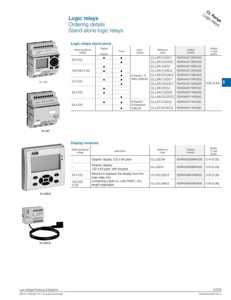
6
CL RangeLogic relays
Low Voltage Products & Systems 6.279ABB Inc. • 888-385-1221 • www.abb.us/lowvoltage 1SXU000023C0202 Rev. A
Logic relays stand alone
Rated operational voltage
Display+
KeypadTimer
Input /Output
Reference code
Catalognumber
Weight(1 pce)kg (lb)
24 V ACJ J
8 inputs / 4 relay outputs
CL-LSR.C12AC1 1SVR440712R0300
0.20 (0.44)
J CL-LSR.CX12AC1 1SVR440712R0200
100-240 V ACJ CL-LSR.12AC2 1SVR440713R0100
J J CL-LSR.C12AC2 1SVR440713R0300
J CL-LSR.CX12AC2 1SVR440713R0200
12 V DCJ J CL-LSR.C12DC1 1SVR440710R0300
J CL-LSR.CX12DC1 1SVR440710R0200
24 V DCJ CL-LSR.12DC2 1SVR440711R0100
J CL-LSR.C12DC2 1SVR440711R0300
J CL-LSR.CX12DC2 1SVR440711R0200
24 V DCJ J 8 inputs /
4 transistor outputs
CL-LST.C12DC2 1SVR440711R1300
J CL-LST.CX12DC2 1SVR440711R1200
Display modules
Rated operational voltage
DescriptionReference
codeCatalognumber
Weight(1 pce)kg (lb)
- Graphic display 132 x 64 pixel CL-LDD.XK 1SVR440839R4500 0.14 (0.30)
-Graphic display 132 x 64 pixel, with keypad
CL-LDD.K 1SVR440839R4400 0.13 (0.29)
24 V DC Module to displace the display from the logic relay, incl. connecting cable CL-LAD.TK007, 5m, lenght adaptable
CL-LDC.SDC2 1SVR440841R0000 0.16 (0.36)
100-240 V DC CL-LDC.SAC2 1SVR440843R0000 0.16 (0.36)
CL-LSR
CL-LST
CL-LDD.K
CL-LDC.S..
Logic relaysOrdering detailsStand alone logic relays

6
CL Range
Logic relays
6.280 Low Voltage Products & Systems
1SXU000023C0202 Rev. A ABB Inc. • 888-385-1221 • www.abb.us/lowvoltage
Logic relays expandable
Rated operational voltage
Display+
KeypadTimer
Input /Output
Reference code
Catalognumber
Weight(1 pce)kg (lb)
24 V ACJ J
12 inputs / 6 relay outputs
CL-LMR.C18AC1 1SVR440722R0300
0.36 (0.79)
J CL-LMR.CX18AC1 1SVR440722R0200
100-240 V AC
J J CL-LMR.C18AC2 1SVR440723R0300
J CL-LMR.CX18AC2 1SVR440723R0200
12 V DCJ J CL-LMR.C18DC1 1SVR440720R0300
J CL-LMR.CX18DC1 1SVR440720R0200
24 V DCJ J CL-LMR.C18DC2 1SVR440721R0300
J CL-LMR.CX18DC2 1SVR440721R0200
24 V DCJ J 12 inputs,
8 transistor outputs
CL-LMT.C20DC2 1SVR440721R13000.36 (0.79)
J CL-LMT.CX20DC2 1SVR440721R1200
Expansions
Rated operational voltage DescriptionReference
codeCatalognumber
Weight(1 pce)kg (lb)
- 2 relay outputs CL-LER.2O 1SVR440709R5000 0.07 (0.15)
100-240 V AC12 inputs, 6 relay outputs
CL-LER.18AC2 1SVR440723R0000 0.26 (0.57)
24 V DC CL-LER.18DC2 1SVR440721R0000 0.22 (0.49)
24 V DC 12 inputs, 8 transistor outputs CL-LET.20DC2 1SVR440721R1000 0.21 (0.46)
-Coupler unit for remote
expansion with a distanceof up to 30 m
CL-LEC.CI000 1SVR440709R0000 0.07 (0.15)
CL-LER
CL-LEC
CL-LMR
Logic relaysOrdering detailsExpandable logic relays

6
CL RangeLogic relays
Low Voltage Products & Systems 6.281ABB Inc. • 888-385-1221 • www.abb.us/lowvoltage 1SXU000023C0202 Rev. A
CL-LA...
DescriptionReference
codeCatalognumber
Weight(1 pce)kg (lb)
Software for programming and control of CL range devices. Installation CD-ROM for Microsoft WindowsTM. CL-LAS.PS002 1SVR440799R8000 0.10
(0.21)
Memory module for logic relaysMemory size: 32 kB CL-LAS.MD003 1SVR440799R7000 0.02 (0.04
Cable with serial interface to connect PC and logic relay. Length: 2 m CL-LAS.TK001 1SVR440799R6000 0.10 (0.22)
Cable with USB interface to connect PC and logic relay CL-LAS.TK002 1SVR440799R6100 0.06 (0.13)
Cable for point-to-point connection of remote-display con-nection module and logic relay, length adaptable CL-LAD.TK007 1SVR440899R6600 0.20 (0.44)
Fixing brackets for screw mounting of logic relay, expan-sion, display base module CL-LAS.FD001 1SVR440799R5000 0.01 (0.01)
Spare plug (CL-LINK) for connection of logic relay to expansion CL-LAS.TK011 1SVR440799R5100 0.10 (0.22)
Primary switch mode power supplies, Rated input voltage: 100-240 V ACRated output voltage/current: 24 V DC / 0.42 A
CP-D 24/0.421) 1SVR427041R0000 0.06 (0.13)
Primary switch mode power supplies, Rated input voltage: 100-240 V ACRated output voltage/current: 24 V DC / 1.3 A
CP-D 24/1.32) 1SVR427043R0100 0.19 (0.41)
1) replaces CL-LAS.SD001, technical data see chapter “Primary switch mode power supplies”2) replaces CL-LAS.SD002, technical data see chapter “Primary switch mode power supplies”
CL-LAS.PS002
CL-LAS.MD003
CL-LAS.TK001
Logic relaysOrdering details

6
CL Range
Logic relays
6.282 Low Voltage Products & Systems
1SXU000023C0202 Rev. A ABB Inc. • 888-385-1221 • www.abb.us/lowvoltage
Display systems
Rated operational voltage
DescriptionReference
codeCatalognumber
Weight(1 pce)kg (lb)
-Display module
Graphic display 132 x 64 pixelCL-LDD.XK 1SVR440839R4500 0.14 (0.30)
-Display module
Graphic display 132 x 64 pixel, with keypad
CL-LDD.K 1SVR440839R4400 0.13 (0.29)
24 V DC Display base module CPU / power supply
CL-LDC.LDC2 1SVR440821R00000.16 (0.36)
100-240 V AC CL-LDC.LAC2 1SVR440823R0000
24 V DC Display base module CPU / power supply, networking-compa-
tible (CL-NET)
CL-LDC.LNDC2 1SVR440821R10000.17 (0.38)
100-240 V AC CL-LDC.LNAC2 1SVR440823R1000
100-240 V AC Display I/O module12 inputs, 4 relay outputs
CL-LDR.16AC2 1SVR440853R00000.17 (0.38)
24 V DC CL-LDR.16DC2 1SVR440851R0000
24 V DCDisplay I/O module
12 inputs, 4 relay outputs, 1 analog output
CL-LDR.17DC2 1SVR440851R2000 0.17 (0.38)
24 V DCDisplay I/O module
12 inputs, 4 transistor outputsCL-LDT.16DC2 1SVR440851R1000 0.14 (0.30)
24 V DCDisplay I/O module
12 inputs, 4 transistor outputs, 1 analog output
CL-LDT.17DC2 1SVR440851R3000 0.14 (0.30)
CL-LDD.K
CL-LDC.LN..
CL-LAD...
DescriptionReference
codeCatalognumber
Weight(1 pce)kg (lb)
Memory module for display base modules Memory size: 256 kB CL-LAD.MD004 1SVR440899R7000 0.02 (0.03)
Cable with serial interface to connect PC and display base module CL-LAD.TK001 1SVR440899R6000 0.11 (0.23)
Cable with USB interface to connect PC and display base module CL-LAD.TK011 1SVR440899R6700
Network cable (CL-NET) to connect 2 display base mod-ules Length: 0.3 m CL-LAD.TK002 1SVR440899R6100 0.05 (0.12)
Network cable (CL-NET) to connect 2 display base mod-ules Length: 0.8 m CL-LAD.TK003 1SVR440899R6200 0.07 (0.14)
Network cable (CL-NET) to connect 2 display base mod-ules Length: 1.5 m CL-LAD.TK004 1SVR440899R6300 0.08 (0.18)
Cable for point-to-point connection of remote display connection modules and display base module, length adaptable, Length: 5 m
CL-LAD.TK005 1SVR440899R6400 0.20 (0.44)
Cable for point-to-point connection of 2 display base modules, length adaptable. Length: 5 m CL-LAD.TK006 1SVR440899R6500 0.12 (0.26)
Termination resistor, content: 2 pieces CL-LAD.TK009 1SVR440899R6900 0.01 (0.02)
Protective cover, transparent, for harsh environmental conditions and application in the food industry CL-LAD.FD001 1SVR440899R1000 0.03 (0.07)
Protective cover, transparent and sealable CL-LAD.FD011 1SVR440899R2000 0.03 (0.07)
Assembly tool for mounting of display modules CL-LAD.FD002 1SVR440899R3000
CL-LAD.MD004
CL-LAD.TK001
CL-LAD.TK002
Logic relaysOrdering detailsDisplay systems

6
CL RangeLogic relays
Low Voltage Products & Systems 6.283ABB Inc. • 888-385-1221 • www.abb.us/lowvoltage 1SXU000023C0202 Rev. A
Data at Ta = 25 °C and rated values, if nothing else indicated.
Type CL-LSR.C...12DC1 CL-LSR....12DC2 CL-LST.C...12DC2 CL-LSR.C...12AC1 CL-LSR...12AC2
Input circuit - supply circuitRated operational voltage Ue 12 V DC 24 V DC 24 V AC 100-240 V ACRated operational voltage tolerance -15...+30 % -15...+20 % -15...+10 %Operational voltage range 10.2-15.6 V DC 20.4-28.8 V DC 20.4-26.4 V AC 85-264 V ACRated frequency 0 Hz 50/60 HzRated frequency tolerance - ±5 %Residual ripple m 5 % -Input current at 12 V DC typ. 140 mA - - -
at 24 V DC - typ. 80 mA - -at 24 V AC - - typ. 200 mA -
at 115/120 V AC (60 Hz) - - - typ. 40 mAat 230/240 V AC (50 Hz) - - - typ. 20 mA
Power failure buffering (IEC/EN 61131-2) 10 ms 20 msPower dissipation at 12 V DC typ. 2 W - - -
at 24 V DC - typ. 2 W - -at 24 V AC - - typ 5 VA -
at 115/120 V AC - - - typ. 5 VAat 230/240 V AC - - - typ. 5 VA
Type CL-LMR.C...18DC1 CL-LMR.C...18DC2 CL-LMT.C...20DC2 CL-LMR.C...18AC1 CL-LMR.C...18AC2
Input circuit - supply circuitRated operational voltage Ue 12 V DC 24 V DC 24 V AC 100-240 V ACRated operational voltage tolerance -15...+30 % -15...+20 % -15...+10 %Operational voltage range 10.2-15.6 V DC 20.4-28.8 V DC 20.4-26.4 V AC 85-264 V ACRated frequency 0 Hz 50/60 HzRated frequency tolerance - ±5 %Residual ripple m 5 % -Input current at 12 V DC typ. 200 mA - - -
at 24 V DC - typ. 140 mA - -at 24 V AC - - typ. 300 mA -
at 115/120 V AC (60 Hz) - - - typ. 70 mAat 230/240 V AC (50 Hz) - - - typ. 35 mA
Power failure buffering (IEC/EN 61131-2) 10 ms 20 msPower dissipation at 12 V DC typ. 3.5 W - - -
at 24 V DC - typ. 3.5 W - -at 24 V AC - - typ. 7 VA -
at 115/120 V AC - - - typ. 10 VAat 230/240 V AC - - - typ. 10 VA
Type CL-LER.18DC2 CL-LET.20DC2 CL-LER.18AC2
Input circuit - supply circuitRated operational voltage Ue 24 V DC 100-240 V ACRated operational voltage tolerance -15...+20 % -15...+10 %Operational voltage range 20.4-28.8 V DC 85-264 V ACRated frequency 0 Hz 50/60 HzRated frequency tolerance - ±5 %Residual ripple m 5 % -Input current at 24 V DC typ. 140 mA -
at 115/120 V AC (60 Hz) - typ. 70 mAat 230/240 V AC (50 Hz) - typ. 35 mA
Power failure buffering (IEC/EN 61131-2) 10 ms 20 msPower dissipation at 24 V DC typ. 3.4 W -
at 115/120 V AC - typ. 10 VAat 230/240 V AC - typ. 10 VA
Logic relaysTechnical data

6
CL Range
Logic relays
6.284 Low Voltage Products & Systems
1SXU000023C0202 Rev. A ABB Inc. • 888-385-1221 • www.abb.us/lowvoltage
Data at Ta = 25 °C and rated values, if nothing else indicated.
Type CL-LSR.C...12DC1 CL-LSR....12DC2 CL-LST.C...12DC2 CL-LSR.C...12AC1 CL-LSR.C...12AC2
Input circuit - Digital inputs 12 V DC 24 V DC 24 V AC 115 / 230 V ACNumber 8
Inputs can be used as analog inputs 2 (I7, I8) -
Indication of operational states LCD-Display (if existing)
Electrical isolation from voltage supply no
between digital inputs no
from the outputs yes
Rated operational voltage Ue
12 V DC 24 V DC 24 V AC
Ue on „0“ signal 4 V DC (I1-I8) < 5 V DC (I1-I8) 0-6 V AC (sinusoidal) 0-40 V AC (sinusoidal)
Ue on „1“ signal8 V DC (I1-I8)
> 15 V DC (I1-I6), > 8 V DC (I7, I8)
> 9.5 V DC, 14-26,4 V AC (sinusoidal) (I1-I6),
> 7 V AC (sinusoidal) (I7,I8)
79-264 V AC (sinusoidal)
Rated frequency - 50-60 Hz
Input current on „1“ signal
3.3 mA (at 12 V DC, I1-I6), 1.1 mA (at 12 V DC, I7, I8)
3.3 mA (at 24 V DC, I6-I7), 2.2 mA (at 24 V DC, I7, I8)
4 mA (at 24 V AC, 50 Hz, I1-I6),
2 mA (at 24 V AC, 50 Hz, I7,I8),
2 mA (at 24 V DC, I7, I8)
6x0.25 mA (at 115 V AC, 60 Hz, I1-I6),
6x0.5 mA (at 230 V AC, 50 Hz, I1-I6)
2x4 mA (at 115 V AC, 60 Hz, I7, I8),
2x6 mA (at 230 V AC, 50 Hz, I7, I8)
Time delay from „0“ to „1“
debounce ON 20 ms 80 ms (at 50 Hz), 66 2/3 ms (at 60 Hz)
debounce OFF typ. 0.3 ms (I1-I6), typ. 0.35 ms (I7, I8)
typ. 0,25 ms (I1-I8) 20 ms (at 50 Hz), 16 2/3 ms (at 60 Hz)
Time delay from „1“ to „0“
debounce ON
20 ms80 ms (at 50 Hz,
66 2/3 ms (at 60 Hz)
80 ms (at 50 Hz, I1-I6), 66 2/3 ms (at 60 Hz, I1-I6)160 ms (at 50 Hz, I7, I8), 150 ms (at 60 Hz, I7, I8)
debounce OFFtyp. 0.3 ms (I1-I6),typ. 0.15 ms (I7, I8)
-20 ms (at 50 Hz),
16 2/3 ms (at 60 Hz)
20 ms (at 50 Hz, I1-I6), 16 2/3 ms (at 60 Hz, I1-I6)100 ms (at 50 Hz, I7. I8), 100 ms (at 60 Hz, I7, I8)
Cable length (unshielded) 100 m - -
Maximum cable length per input - 40 m 40 m (I1-I6), 100 m (I7, I8)
Frequency counter Number 2 (I3, I4) - -
counting frequency < 1 kHz - -
pulse shape square-wave - -
pulse / pause ratio 1:1 - -
Rapid counter inputs Number 2 (I1, I2) - -
counting frequency < 1 kHz - -
pulse shape square-wave - -
pulse / pause ratio 1:1 - -
Cable length (shielded) < 20 m - -
Input circuit - Analog inputsNumber 2 (I7, I8) -
Electrical isolation from voltage supply no -
from the digital inputs no -
from the outputs yes -
from PC interface, memory module, CL-NET, CL-LINK no -
Input type DC voltage -
Signal range 0-10 V DC -
Resolution analog 0.01 V -
digital 0.01 V; 10 Bit (value 1-1023) -
Input impedance 11.2 kq -
Accuracy of the actual value
two CL devices ±3 % -
within one device ±2 %, ±0.12 V -
Conversion time analog/digital
Input delay ON 20 ms -
Input delay OFF each cycle -
Input current < 1 mA -
Cable length (shielded) < 30 m -
Logic relaysTechnical data

6
CL RangeLogic relays
Low Voltage Products & Systems 6.285ABB Inc. • 888-385-1221 • www.abb.us/lowvoltage 1SXU000023C0202 Rev. A
Data at Ta = 25 °C and rated values, if nothing else indicated.
Type CL-LMR.C...18DC1 CL-LMR.C...18DC2 CL-LMT.C...20DC2 CL-LMR.C...18AC1 CL-LMR.C...18AC2
Input circuit - Digital inputs 12 V DC 24 V DC 24 V AC 115 / 230 V ACNumber 12Inputs can be used as analog inputs 4 (I7, I8, I11, I12) -Indication of operational states LCD-Display (if existing)Electrical isolation from voltage supply no
between digital inputs nofrom the outputs yes
from PC interface, memory module, CL-NET, CL-LINK no yes
Rated operational voltage Ue
12 V DC 24 V DC 24 V ACUe on „0“ signal 4 V DC (I1-I12) < 5 V DC (I1-I12, R1-R12) 0-6 V AC (sinusoidal) 0-40 V AC (sinusoidal)Ue on „1“ signal
8 V DC (I1-I12)> 15 V DC (I1-I6, I9, I10) > 8 V DC (I7, I8, I11, I12)
> 9.5 V DC, 14-26.4 V AC (sinusoidal) (I1-I6, I9, I10)
> 7 V AC (sinusoidal) (I7,I8; I11, I12)
79-264 V AC (sinusoidal)
Rated frequency - 50-60 HzInput current on „1“ signal
3.3 mA (at 12 V DC, I1-I6, I9-I12),
1.1 mA (at 12 V DC, I7, I8)
3.3 mA (at 24 V DC, I1-I6, I9, I10),
2.2 mA (at 24 V DC, I7, I8, I11, I12)
4 mA (at 24 V AC, 50 Hz, I1-I6,
I9, I10), 2 mA
(at 24 V AC, 50 Hz, I7, I8, I11, I12), 2 mA
(at 24 V DC, I7, I8, I11, I12)
6x0.25 mA (at 115 V AC, 60 Hz, I1-I6),
6x0.5 mA (at 230 V AC, 50 Hz, I1-I6)
2x4 mA (at 115 V AC, 60 Hz, I7, I8),
2x6 mA (at 230 V AC, 50 Hz, I7, I8),
4x0.25 mA (at 115 V AC, 60 Hz,
I9-I12), 4x0.5 mA
(at 230 V AC, 50 Hz, I9-I12)Time delay from „0“ to „1“
debounce ON 20 ms 80 ms (at 50 Hz), 66 2/3 ms (at 60 Hz)debounce OFF typ. 0.3 ms (I1-I6, I9, I10),
typ. 0.35 ms (I7, I8, I11, I12)typ. 0.25 ms 20 ms (at 50 Hz), 16 2/3 ms (at 60 Hz)
Time delay from „1“ to „0“
debounce ON 20 ms 80 ms (at 50 Hz), 66 2/3 ms (at 60 Hz)debounce OFF typ. 0.4 ms (I1-I6, I9, I10),
typ. 0.35 ms (I7, I8, I11, I12)- 20 ms (at 50 Hz), 16 2/3 ms (at 60 Hz)
Cable length (unshielded) 100 mMaximum cable length per input max. 40 m,
typ. 40 m (I9, I10)typ. 40 m (I1-I6, I9-I12),
typ. 100 m (I7, I8)Frequency counter number 2 (I3, I4) - -
counting frequency < 1 kHz - -pulse shape square-wave - -
pulse / pause ratio 1:1 - -Rapid counter inputs number 2 (I1, I2) - -
counting frequency < 1 kHz - -pulse shape square-wave - -
pulse / pause ratio 1:1 - -Cable length (shielded) < 20 m - -
Input circuit - Analog inputsNumber 4 (I7, I8, I11, I12) -Electrical isolation from voltage supply no -
from the digital inputs no -from the outputs yes -
from PC interface, memory module, CL-NET, CL-LINK no -
Input type DC voltage -Signal range 0-10 V DC -Resolution analog 0.01 V -
digital 0.01 V; 10 Bit (value 1-1023) -Input impedance 11.2 kq -Accuracy of the actual value
two CL devices ±3 % -within one device ±2 %, ±0.12 V -
Conversion time analog/digital
Input delay ON 20 ms -Input delay OFF each cycle -
Input current < 1 mA -Cable length (shielded) < 30 m -
Logic relaysTechnical data

6
CL Range
Logic relays
6.286 Low Voltage Products & Systems
1SXU000023C0202 Rev. A ABB Inc. • 888-385-1221 • www.abb.us/lowvoltage
Data at Ta = 25 °C and rated values, if nothing else indicated.
Type CL-LER.18DC2 CL-LET.20DC2 CL-LER.18AC2
Input circuit - Digital inputs 24 V DC 115 / 230 V ACNumber 12Inputs can be used as analog inputs -Indication of operational states -Electrical isolation from voltage supply no
between digital inputs no
from the outputs yes
from PC interface, memory module, CL-NET, CL-LINK no
Rated operational voltage Ue
24 V DC
Ue on „0“ signal < 5 V DC (I1-I12, R1-R12) 0-40 V AC (sinusoidal)
Ue on „1“ signal - 79-264 V AC (sinusoidal)
Rated frequency - 50-60 HzInput current on „1“ signal
3.3 mA (at 24 V DC, R1-R12)
12x0.25 mA (at 115 V AC, 60 Hz, R1-R12),
12x0.5 mA (at 230 V AC, 50 Hz, R1-R12)
Time delay from „0“ to „1“
debounce ON 20 ms80 ms (at 50 Hz, I1-I12, R1-R12),
66 2/3 ms (at 60 Hz, I1-I12, R1-R12)
debounce OFF typ. 0.25 ms (R1-R12)20 ms (at 50 Hz, I1-I12, R1-R12),
16 2/3 ms (at 60 Hz, I1-I12, R1-R12)Time delay from „1“ to „0“
debounce ON 20 ms80 ms (at 50 Hz, I1-I12, R1-R12),
66 2/3 ms (at 60 Hz, I1-I12, R1-R12)
debounce OFF -20 ms (at 50 Hz, I1-I12, R1-R12),
16 2/3 ms (at 60 Hz, I1-I12, R1-R12)Cable length (unshielded) 100 m -Maximum cable length per input
-typ. 40 m (I1-I6, I9-I12, R1-R12),
typ. 100 m (I7, I8)
Logic relaysTechnical data

6
CL RangeLogic relays
Low Voltage Products & Systems 6.287ABB Inc. • 888-385-1221 • www.abb.us/lowvoltage 1SXU000023C0202 Rev. A
Data at Ta = 25 °C and rated values, if nothing else indicated.
TypeCL-LSR... CL-LMR...
CL-LER... CL-LER.2O
Output circuit - Relay outputsNumber 4 6 2
Outputs in groups of 1 2
Parallel switching of outputs to increase capacity not permissible
Fusing of the output relay circuit-breaker B16 or fuse 8 A (slow-acting)
Electrical isolation from voltage supply yes
from the inputs yes
from PC interface, memory module, CL-NET, CL-LINK no
protective separation 300 V AC
basic isolation 600 V AC
Mechanical lifetime 10x106 switching cycles
Rung conventional thermal current (10 A UL) 8 A
recommended for load 12 V AC/DC > 500 mA
short-circuit proof cos j = 1; characteristic B16 at 600 A
16 A
short-circuit proof cos j = 0.5 up to 0.7; characteristic B16 at 900 A
16 A
Rated impulse withstand voltage Uimp contact-coil 6 kV
Rated operational voltage Ue 250 V AC
Rated insulation voltage Ui 250 V AC
Protective separation (EN 50178) between coil and contact 300 V AC
between two contacts 300V AC
Making capacity AC15, 250 V AC, 3 A (600 ops./h) 300.000 switching cycles
DC13, L/R m 150 ms, 24 V DC, 1 A (500 ops./h) 200.000 switching cycles
Breaking capacity AC15, 250 V AC, 3 A (600 ops./h) 300.000 switching cycles
DC13, L/R m 150 ms, 24 V DC, 1 A (500 ops./h) 200.000 switching cycles
Incandesent lamp load 1000 W at 230/240 V AC 25.000 switching cycles
500 W at 115/120 V AC 25.000 switching cycles
Fluorescent lamp load 10 x 58 W at 230/240 V AC with electrical control gear
25.000 switching cycles
10 x 58 W at 230/240 V AC uncompensated
25.000 switching cycles
1 x 58 W at 230/240 V AC conventional compensated
25.000 switching cycles
Switching frequency mechanical operations 10x106
switching frequency 10 Hz
resistive load / lamp load 2 Hz
inductive load 0.5 Hz
UL/CSAContinuous current at 240 V 10 A AC
Continuous current at 24 V 8 A DC
AC Utilization catagory (Control Circuit Rating Codes) B 300 Light Pilot Duty
max. rated operational voltage 300 V AC
max. continuous thermal current cos j = 1 at B 300
5 A
max. making / breaking apparent power (Make/Break) cos j ≠ 1 at B 300
3600/360 VA
DC Utilization catagory (Control Circuit Rating Codes) R 300 Light Pilot Duty
max. rated operational voltage 300 V DC
max. continuous thermal current at R 300 1 A
max. making / breaking apparent power (Make/Break) at R 300
28/28 VA
Logic relaysTechnical data

6
CL Range
Logic relays
6.288 Low Voltage Products & Systems
1SXU000023C0202 Rev. A ABB Inc. • 888-385-1221 • www.abb.us/lowvoltage
Data at Ta = 25 °C and rated values, if nothing else indicated.
Type CL-LST... CL-LMT... CL-LET...
Output circuit - Transistor outputsNumber 4 8
Rated operational voltage Ue 24 V DC
Operational voltage range 20.4-28.8 V DC
Residual ripple m 5 %
Supply current on „0“ signal typ. 9 mA / max. 16 mA
typ. 18 mA / max. 32 mA
on „1“ signal typ. 12 mA / max. 22 mA
typ. 24 mA / max. 44 mA
Reverse voltage protection yes (Attention: If supply voltage is reversed, applying voltage at the outputs, causes a short circuit.)
Electrical isolation from voltage supply yes
from the inputs yes
from PC interface, memory module, CL-NET, CL-LINK
-
Rated operational current Ie on„1“ signal DC max. 0.5 A
Lamp load without Rv 5 W
Residual current on „0“ signal per channel < 0.1 mA
Max. output voltage on „0“ signal at external load < 10 Mq 2.5 V
on „1“ signal at Ie = 0.5 A U = Ue - 1 V
Short-circuit protection yes, thermal (analysis results from diagnosis input I16, I15; R15, R16)
Short-circuit tripping current for Ra m 10 mq 0.7 A m Ie m 2 A per output
Total short-circuit current 8 A 16 A
Peak short-circuit current 16 A 32 A
Thermal tripping yes
Max. switching frequency with constant resistive load RL < 100 kq (depending on active channels and their load)
40.000 switching cycles/h
Parallel connection of outputs with resistive load, inductive load with external suppressor, combination within one group
group 1: Q1-Q4group 1: Q1-Q4, group 2: Q5-Q8
group 1: S1-S4, group 2: S5-S8
number of outputs max. 4
max. total current 2 A (Attention! Outputs must be actuated simultaneously and for the same length of time.)
Indication of operational states of the outputs LCD-Display (if existing)
Inductive load1) without external suppressor
T0.95 = 1 ms, R = 48 q, L = 16 mH
utilization factor 0.25 g
duty time 100 %
max. switching frequency f = 0.5 Hz (max. duty time = 50 %)
1500 switching cycles
DC13, T0.95 = 72 ms, R = 48 q, L = 1.15 H
utilization factor 0.25 g
duty time 100 %
max. switching frequency f = 0.5 Hz (max. duty time = 50 %)
1500 switching cycles
T0.95 = 15 ms, R = 48 q, L = 0.24 H
utilization factor 0.25 g
duty time 100 %
max. switching frequency f = 0.5 Hz (max. duty time = 50 %)
1500 switching cycles
Inductive load1) with external suppressor
demand factor 1 g
duty time 100 %
max. switching frequency max. duty time
depends on suppressor
1) For inductive loading, without external suppression of the transistor outputs, the following applies: T0.95 = time in ms, until 95 % of the steady-state current is achieved. T0.95 3 × T0.65 = 3 × L/R.
Data transfer rate in the CL-NET network: bus lengths of 40 m and over only attainable with cables with additional cross-section and connection adapter.
Logic relaysTechnical data

6
CL RangeLogic relays
Low Voltage Products & Systems 6.289ABB Inc. • 888-385-1221 • www.abb.us/lowvoltage 1SXU000023C0202 Rev. A
Data at Ta = 25 °C and rated values, if nothing else indicated.
Type CL-LSR..., CL-LST... CL-LMR... CL-LMT.. CL-LET.., CL-LER.18..
CL-LER.2O CL-LEC.CI000
General dataDimensions (W x H x D)
71.5 mm x 90 mm x 58 mm (2.81 inch x 3.54 inch x
2.28 inch)
107.5 mm x 90 mm x 58 mm
(4.23 inch x 3.54 inch x 2.28 inch)
35.5 mm x 90 mm x 58 mm (1.40 inch x 3.54 inch x
2.28 inch)
Weight 0.2 kg (0.44 lb) 0.3 kg (0.66 lb) 0.07 kg (0.15 lb)Mounting DIN rail (IEC/EN 60715),
35 mm or screw mounting with fixing brackets CL-LAS.FD001 (accessories)Mounting position horizontal / verticalElectrical connectionWire size rigid 0.2-4 mm2 (22–12 AWG)
fine-strand with wire end ferrule 0.2-2.5 mm2 (22–12 AWG)Max. tightening torque 0.6 NmEnvironmental dataAmbient temperature range operation -25...+55 °C, cold acc. to IEC 60068-2-1, heat acc. to IEC 60068-2-2
storage -40...+70 °CLCD-Display (clearly legible) 0...+55 °CCondensation avoid condensation with suitable methodsHumidity, no condensation (IEC/EN 60068-2-30) 5-95 %Air pressure (operation) 795-1080 hPaDegree of protection (IEC/EN 60529) IP20Vibration (IEC/EN 60068-2-6) 10-57 Hz (constant amplitude 0.15 mm), 57-150 Hz (constant acceleration 2 g)Shock resistance (half-sine 15 g / 11 ms) (IEC/EN 60068-2-27) 18 ShocksDrop (IEC/EN 60068-2-31) height of fall 50 mmFree fall, packaged (IEC/EN 60068-2-32) 1 mInsulation dataOvervoltage category IIPollution degree (DIN EN 60947) 2Rating of air and creepage distances EN 50178, UL 508, CSA C22.2, No. 142Insulation resistance EN 50178StandardsStandards and directives EN 55011, EN 55022, IEC/EN 61000-4, IEC 60068-2-6, IEC 60068-2-27Electromagnetic compatibilityInterference immunity
electrostatic discharge (ESD) IEC/EN 61000-4-2 Level 3 (air discharge 8 kV, contact discharge 6 kV)electromag. field (HF radiation resistance) IEC/EN 61000-4-3 10 V/mfast transients (Burst) IEC/EN 61000-4-4 Level 3 (supply cable 2 kV, signal lines 2 kV)powerful impulses (Surge) IEC/EN 61000-4-5 supply cable symmetrical (AC) 2 kV,
Level 2 (supply cable symmetrical (DC) 0.5 kV)HF line emission IEC/EN 61000-4-6 10 V
Interference suppression (EN 55011, EN 55022) class BReal time clockBack-up time see diagram -Accuracy typ. ±5 (±0.5 h/year) -Repeat accuracy of the time relayAccuracy (from value) ±1 -Resolution range „S“ 10 ms -
range „M:S“ 1 s -range „H:M“ 1 min -
Retention behaviourWrite cycles of retention memory (minimum) 1.000.000 (106) -
180200
160140120100806040200
55 ˚C
25 ˚C
0 1 2 3 4 5 6 7 8 9 10 11 12 13 14 15 16 17 18 19 20
Buf
fer
time
(hou
rs)
Operating time (years)
Technical diagram
Back-up time of the real time clock
Logic relaysTechnical data

6
CL Range
Logic relays
6.290 Low Voltage Products & Systems
1SXU000023C0202 Rev. A ABB Inc. • 888-385-1221 • www.abb.us/lowvoltage
Data at Ta = 25 °C and rated values, if nothing else indicated.
Type CL-LDD...
Input circuit - Supply circuitPower failure buffering (IEC/EN 61131-2) 10 ms
General dataDimensions (W x H x D) with keypad:
86.5 x 86.5 x 21.5 mm (3.41 x 3.41 x 0.85 inch)without keypad:
86.5 x 86.5 x 20 mm (3.41 x 3.41 x 0.79 inch)
Weight 0.13 kg (0.29 lb)
Mounting 2 x 22.5 mm, with 2 retainers screwed
Mounting position horizontal / vertical
Environmental dataAmbient temperature range operation -25...+55 °C (cold acc. to IEC 60068-2-1, heat acc. to IEC 60068-2-2)
storage -40...+70 °C
LCD-Display (clearly legible) -5...+50 °C,-10...0 °C (with backlit / continuous operation)
Condensation avoid condensation with suitable methods
Humidity, no condensation (IEC/EN 60068-2-30) 5-95 %
Air pressure (operation) 795-1080 hPa
Degree of protection (IEC/EN 60529) IP65
Vibration (IEC/EN 60068-2-6) 10-57 Hz (constant amplitude 0.15 mm), 57-150 Hz (constant accelera-tion 2 g)
Shock resistance (half-sine 15 g / 11 ms) (IEC/EN 60068-2-27) 18 Shocks
Drop (IEC/EN 60068-2-31) height of fall 50 mm
Free fall, packaged (IEC/EN 60068-2-32) 1 m
Insulation dataPollution degree (DIN EN 60947) 3
Rating of air and creepage distances EN 50178, UL 508, CSA 22.2, No 142
Insulation resistance EN 50178
StandardsStandards and directives EN 61000-6-1, EN 61000-6-2, EN 61000-6-3, EN 61000-6-4,
IEC 60068-2-6, IEC 60068-2-27
Electromagnetic compatibilityInterference immunity
electrostatic discharge (ESD) IEC/EN 61000-4-2 Level 3 (air discharge 8 kV, contact discharge 6 kV)
electromag. field (HF radiation resistance) IEC/EN 61000-4-3 10 V/m
fast transients (Burst) IEC/EN 61000-4-4 Level 3 (supply cable 2 kV, signal lines 2 kV)
powerful impulses (Surge) IEC/EN 61000-4-5 Level 3 (supply cable symmetrical 2 kV, CL-LDC.L...AC2)
Level 2 (0.5 kV supply cable symmetrical, CL-LDC.L...AC2)
HF line emission IEC/EN 61000-4-6 10 V
Interference suppression (EN 55011, EN 55022) class B
Logic relaysTechnical data

6
CL RangeLogic relays
Low Voltage Products & Systems 6.291ABB Inc. • 888-385-1221 • www.abb.us/lowvoltage 1SXU000023C0202 Rev. A
Data at Ta = 25 °C and rated values, if nothing else indicated.
Type CL-LDC.
SDC2
CL-LDC.
SAC2
CL-LDC.
LDC2
CL-LCD.
LAC2
CL-LDC.
LNDC2
CL-LDC.
LNAC2Input circuit - Supply circuitRated operational voltage Ue 24 V DC 100-240 V AC 24 V DC 100-240 V AC 24 V DC 100-240 V ACRated operational voltage tolerance -15...+20 % -15...+10 % -15...+20 % -15...+10 % -15...+20 % -15...+10 %Operational voltage range 20.4-28.8 V DC 85-264 V AC 20.4-28.8 V DC 85-264 V AC 20.4-28.8 V DC 85-264 V ACFrequency 0 Hz 50/60 Hz 0 Hz 50/60 Hz 0 Hz 50/60 HzFrequency tolerance - ± 5 % - ± 5 % - ± 5 %Residual ripple m 5 % - m 5 % - m 5 % -Input current at 24 V DC typ. 185 mA - typ. 200 mA - typ. 200 mA -
at 115/120 V AC (60 Hz) - typ. 90 mA - typ. 90 mA - typ. 90 mAat 230/240 V AC (50 Hz) - typ. 60 mA - typ. 60 mA - typ. 60 mA
Power failure buffering (IEC/EN 61131-2) 10 msPower dissipation at 24 V DC 1.5 W - 3.4 W - 3.4 W -
at 115/120 V AC - typ. 11 VA - typ. 11 VA - typ. 11 VAat 230/240 V AC - typ. 15 VA - typ. 15 VA - typ. 15 VA
Network - point-to-point connectionNumber of stations 1 -Data transfer rate CL-LS..., CL-LM... 9.6 kBaud -
CL-LDD 19.2 kBaud -Distance max. 5 m -Electrical isolation to voltage supply yes -
to connected device yes -Termination system spring-type terminal -
Network - CL-NETNumber of stations max. 1 - max. 8Data transfer rate 6 m - 1000 kBit/s
25 m - 500 kBit/s40 m - 250 kBit/s
125 m - 125 kBit/s300 m - 50 kBit/s700 m - 20 kBit/s
1000 m - 10 kBit/sElectrical isolation to voltage supply - yes
to inputs - yesto outputs - yes
to PC interface, memory module, CL-NET, CL-LINK - yes
Bus terminator (first and last station) - yesTermination system - RJ45, 8 pole
General dataDimensions (W x H x D) 75 x 58 x 36.2 mm
(2.95 x 2.28 x 1.43 inch)107.5 x 90 x 30 mm
(4.23 x 3.54 x 1.18 inch)Weight 0.164 kg (0.36 lb) 0.145 kg (0.32 lb)Mounting
plugged onto CL-LDDplugged onto CL-LDD or
on DIN rail (IEC/EN 60715)Mounting position
Electrical connection - Supply circuitWire size fine-strand with wire end
ferrule 0.2 mm2 / 2.5 mm2 (24-12 AWG)
rigid 0.2 mm2 / 4 mm2 (24-12 AWG)Electrical connection - Data cableWire size fine-strand with wire end
ferrule 0.08 mm2 / 1.5 mm2 (28-12 AWG) - 0.2 mm2 / 2.5 mm2 (24-12 AWG)
rigid 0.08 mm2 / 2.5 mm2 (28-12 AWG) - 0.2 mm2 / 4 mm2 (24-12 AWG)
Environmental dataAmbient temperature range operation -25...+55 °C (cold acc. to IEC 60068-2-1, heat acc. to IEC 60068-2-2)
storage -40...+70 °CCondensation avoid condensation with suitable methodsHumidity, no condensation (IEC/EN 60068-2-30) 5-95 %Air pressure (operation) 795-1080 hPaDegree of protection (IEC/EN 60529) IP20Vibration (IEC/EN 60068-2-6) 10-57 Hz (constant amplitude 0.15 mm), 57-150 Hz (constant acceleration 2 g)
Logic relaysTechnical data

6
CL Range
Logic relays
6.292 Low Voltage Products & Systems
1SXU000023C0202 Rev. A ABB Inc. • 888-385-1221 • www.abb.us/lowvoltage
Data at Ta = 25 °C and rated values, if nothing else indicated.
Type CL-LDC.
SDC2
CL-LDC.
SAC2
CL-LDC.
LDC2
CL-LCD.
LAC2
CL-LDC.
LNDC2
CL-LDC.
LNAC2Shock (half-sine 15 g / 11 ms) (IEC/EN 60068-2-27) 18 Shocks
Drop (IEC/EN 60068-2-31) height of fall 50 mm
Free fall, packaged (IEC/EN 60068-2-32) 1 m
Insulation dataDegree of protection (DIN EN 60947) 2
Rating of air and creepage distances EN 50178, UL 508, CSA 22.2, No 142
Isolation resistance EN 50178
StandardsStandards and directives EN 61000-6-1, EN 61000-6-2, EN 61000-6-3, EN 61000-6-4, IEC 60068-2-6, IEC 60068-2-27
Electromagnetical compatibilityInterference immunity
electrostatic discharge (ESD) IEC/EN 61000-4-2 Level 3 (air discharge 8 kV, contact discharge 6 kV)
electromag. field (HF radiation resistance) IEC/EN 61000-4-3 10 V/m
fast transients (Burst) IEC/EN 61000-4-4 Level 3 (supply cable 2 kV, signal lines 2 kV)
powerful impulses (Surge) IEC/EN 61000-4-5 Level 3 (supply cable symmetrical 2 kV, CL-LDC.L...AC2)
Level 2 (1 kV supply cable symmetrical)
Level 2 (0.5 kV supply cable symmetrical, CL-LDC.L...AC2)
HF line emission IEC/EN 61000-4-6 10 V
Interference suppression (EN 55011, EN 55022) class B
Real time clockBack-up time - see diagram
Accuracy - typ. ± 5 s/day (± 0,5 h/year)
Repeat accuracy of the time relayAccuracy (from value) - ± 0.02 %
Resolution range „S“ - 5 ms
range „M:S“ - 1 s
range „H:M“ - 1 min
Retention behaviourWrite cycles of retention memory (minimum) - 1010 (read/ write cycles)
180200
160140120100806040200
55 ˚C
25 ˚C
0 1 2 3 4 5 6 7 8 9 10 11 12 13 14 15 16 17 18 19 20
Buf
fer
time
(hou
rs)
Operating time (years)
Technical diagram
Back-up time of the real time clock
Logic relaysTechnical data

6
CL RangeLogic relays
Low Voltage Products & Systems 6.293ABB Inc. • 888-385-1221 • www.abb.us/lowvoltage 1SXU000023C0202 Rev. A
Data at Ta = 25 °C and rated values, if nothing else indicated.
Type CL-LD...16DC2 CL-LD...17DC2 CL-LDR.16AC2Input circuit - Digital inputs 24 V DC 115/230 VNumber 12
Inputs can be used as analog inputs 4 (I7, I8, I11, I12) -
Indication of operational states - LCD-Display (if existing)
Electrical isolation from supply voltage no
from digital inputs no
from the outputs yes
from PC interface, memory module, CL-NET, CL-LINK yes
Rated operational voltage Ue 24 V DC -
Ue on „0“ signal < 5 V DC (I1-I6, I9, I10), < 8 V DC (I7, I8, I11, I12) 0-40 V AC (sinusoidal)
Ue on „1“ signal > 15 V DC (I1-I6, I9, I10), > 8 V DC (I7, I8, I11, I12) 79-264 V AC (sinusoidal)
Rated frequency 0 Hz 50-60 Hz
Input current on „1“ signal 3.3 mA (at 24 V DC, I1-I6, I9, I10),
2.2 mA (at 24 V DC, I7, I8, I11, I12)
12x0.2 mA (at 115 V AC, 60 Hz, I1-I12),
12x0.5 mA (at 230 V AC, 50 Hz, I1-I12)
Time delay from „0“ to „1“
debounce ON20 ms
10 ms (at 50 Hz), 100 ms (at 60 Hz)
debounce OFFtyp. 0.1 ms (I1-I4), typ. 0.25 ms (I5-I12)
10 ms (at 50 Hz), 100 ms (at 60 Hz)
Time delay from „1“ to „0“
debounce ON20 ms
10 ms (at 50 Hz), 100 ms (at 60 Hz)
debounce OFF typ. 0.1 ms (I1-I4), typ. 0.4 ms (I5, I6, I9, I10), typ. 0.2 ms (I7, I8, I11, I12)
10 ms (at 50 Hz), 100 ms (at 60 Hz)
Cable length (unshielded) 100 m -
Maximum cable length per input - typ. 60 m
Frequency counter number 4 (I1, I2, I3, I4) -
counting frequency < 3 kHz -
pulse shape square-wave -
pulse / pause ratio 1:1 -
Incremental counter number 2 (I1 + I2, I3 + I4) -
counting frequency < 3 kHz -
pulse shape square-wave -
signal offset 90° -
pulse / pause ratio 1:1 -
Rapid counter inputs number 4 (I1, I2, I3, I4) -
counting frequency < 3 kHz -
pulse shape square-wave -
pulse / pause ratio 1:1 -
Cable length (shielded) < 20 m -
Input circuit - Analog inputsNumber 4 (I7, I8, I11, I12) -
Electrical isolation to voltage supply no -
to digital inputs no -
to outputs yes -
to PC interface, memory modul, CL-NET, CL-LINK yes -
Input type DC voltage -
Signal range 0-10 V DC -
Resolution analog 0.01 V -
digital 0.01 V; 10 Bit (value 0-1023) -
Input impedance 11.2 kq -
Accuracy of the actual value two CL-LD... devices ± 3 % -
within one device ± 2 % -
Conversion time analog/digital each cycle -
Input current < 1 mA -
Cable length (shielded) < 30 m -
Logic relaysTechnical data

6
CL Range
Logic relays
6.294 Low Voltage Products & Systems
1SXU000023C0202 Rev. A ABB Inc. • 888-385-1221 • www.abb.us/lowvoltage
Data at Ta = 25 °C and rated values, if nothing else indicated.
Type CL-LD...16DC2 CL-LD...17DC2 CL-LDR.16AC2Output circuit - Analog outputsNumber - 1 -
Electrical separation from voltage supply - no -
from the digital inputs - no -
from the digital outputs - yes -
from PC interface, memory module, CL-NET, CL-LINK - yes -
Output type - DC voltage -
Signal range - 0-10 V DC -
Max. output current - 0.01 A -
Burden resistance - 1 kq -
Overload and short-circuit protection - yes -
Resolution analog - 0.01 V DC -
digital - 10 Bit, (value: 0-1023) -
Setting time - 100 ms -
Accuracy -25...+55 °C - 2 % -
25 °C - 1 % -
Conversion time - each CPU cycle -
General dataDimensions (W x H x D) CL-LDR: 89 x 90 x 44 mm (3.5 x 3.54 x 1.73 inch)
CL-LDT (build-in): 89 x 90 x 25 mm (3.5 x 3.54 x 0.98 inch)
89 x 90 x 44 mm
(3.5 x 3.54 x 1.73 inch)
Weight CL-LDR: 0.15 kg (0.33 lb) / CL-LDT: 014 kg (0.31 lb) 0.15 kg (0.33 lb)
Mounting snap-on power supply unit
Mounting position horizontal / vertical
Electrical connectionWire size fine-strand with wire end ferrule 0.2 mm2 / 2.5 mm2 (24-12 AWG)
rigid 0.2 mm2 / 4 mm2 (24-12 AWG)
Electrical connection - Data cableWire size fine-strand with wire end ferrule 0.08 mm2 / 1.5 mm2 (28-12 AWG)
rigid 0.08 mm2 / 2.5 mm2 (28-12 AWG)
Environmental dataAmbient temperature range operation -25...+55 °C (cold acc. to IEC 60068-2-1, heat acc. to IEC 60068-2-2)
storage -40...+70 °C
Condensation avoid condensation with suitable methods
Humidity, no condensation (IEC/EN 60068-2-30) 5-95 %
Atmospheric pressure (operation) 795-1080 hPa
Degree of protection (IEC/EN 60529) IP20
Vibration (IEC/EN 60068-2-6) 10-57 Hz (constant amplitude 0.15 mm), 57-150 Hz (constant acceleration 2 g)
Shock (half-sine 15 g / 11 ms) (IEC/EN 60068-2-27) 18 Shocks
Drop (IEC/EN 60068-2-31) height of fall 50 mm
Free fall, packaged (IEC/EN 60068-2-32) 1 m
Insulation dataPollution degree 2
Rating of air and creepage distances EN 50178, UL 508, CSA C22.2, No. 142
Isolation resistance EN 50178
StandardsStandards and directives EN 61000-6-1/-2/-3/-4, IEC/EN 61000-4, IEC 60068-2-6, IEC 60068-2-27
Electromagnetic compatibilityelectrostatic discharge (ESD) IEC/EN 61000-4-2 Level 3 (air discharge 8 kV, contact discharge 6 kV)
electromag. field (HF radiation res.) IEC/EN 61000-4-3 10 V/m
fast transients (Burst) IEC/EN 61000-4-4 Level 3 (supply cable 2 kV, signal cable 2 kV)
powerful impulses (Surge) IEC/EN 61000-4-5 2 kV (supply cable symmetrical),
Level 2 (0.5 kV supply cable symmetrical)
HF line emission IEC/EN 61000-4-6 10 V
Interference suppression (EN 55011, EN 55022) class B
Logic relaysTechnical data
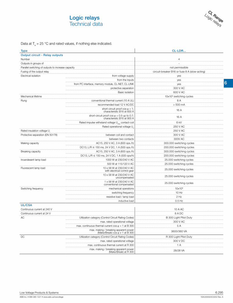
6
CL RangeLogic relays
Low Voltage Products & Systems 6.295ABB Inc. • 888-385-1221 • www.abb.us/lowvoltage 1SXU000023C0202 Rev. A
Data at Ta = 25 °C and rated values, if nothing else indicated.
Type CL-LDR...
Output circuit - Relay outputsNumber 4
Outputs in groups of -
Parallel switching of outputs to increase capacity not permissible
Fusing of the output relay circuit-breaker B16 or fuse 8 A (slow-acting)
Electrical isolation from voltage supply yes
from the inputs yes
from PC interface, memory module, CL-NET, CL-LINK yes
protective separation 300 V AC
Basic isolation 600 V AC
Mechanical lifetime 10x106 switching cycles
Rung conventional thermal current (10 A UL) 8 A
recommended load 12 V AC/DC > 500 mA
short-circuit proof cos j = 1; characteristic B16 at 600 A 16 A
short-circuit proof cos j = 0.5 up to 0.7; characteristic B16 at 900 A 16 A
Rated impulse withstand voltage Uimp contact-coil 6 kV
Rated operational voltage Ue 250 V AC
Rated insulation voltage Ui 250 V AC
Protective separation (EN 50178) between coil and contact 300 V AC
between two contacts 300V AC
Making capacity AC15, 250 V AC, 3 A (600 ops./h) 300.000 switching cycles
DC13, L/R m 150 ms, 24 V DC, 1 A (500 ops./h) 200.000 switching cycles
Breaking capacity AC15, 250 V AC, 3 A (600 ops./h) 300.000 switching cycles
DC13, L/R m 150 ms, 24 V DC, 1 A (500 ops/h) 200.000 switching cycles
Incandesent lamp load 1000 W at 230/240 V AC 25.000 switching cycles
500 W at 115/120 V AC 25.000 switching cycles
Fluorescent lamp load 10 x 58 W at 230/240 V AC with electrical control gear 25.000 switching cycles
10 x 58 W at 230/240 V AC uncompensated 25.000 switching cycles
1 x 58 W at 230/240 V AC conventional compensated 25.000 switching cycles
Switching frequency mechanical operations 10x106
switching frequency 10 Hz
resistive load / lamp load 2 Hz
inductive load 0.5 Hz
UL/CSAContinuous current at 240 V 10 A AC
Continuous current at 24 V 8 A DC
AC Utilization category (Control Circuit Rating Codes) B 300 Light Pilot Duty
max. rated operational voltage 300 V AC
max. continuous thermal current cos j = 1 at B 300 5 A
max. making / breaking apparent power (Make/Break) cos j ≠ 1 at B 300 3600/360 VA
DC Utilization category (Control Circuit Rating Codes) R 300 Light Pilot Duty
max. rated operational voltage 300 V DC
max. continuous thermal current at R 300 1 A
max. making / breaking apparent power (Make/Break) at R 300 28/28 VA
Logic relaysTechnical data
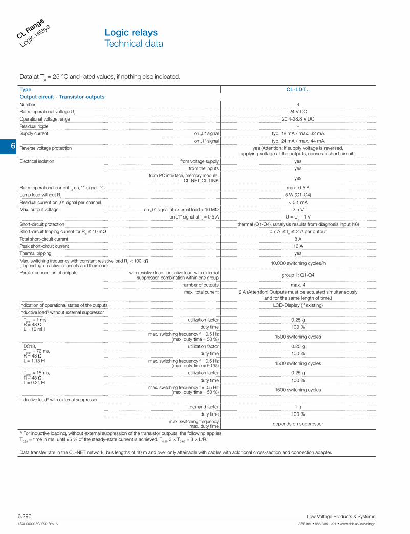
6
CL Range
Logic relays
6.296 Low Voltage Products & Systems
1SXU000023C0202 Rev. A ABB Inc. • 888-385-1221 • www.abb.us/lowvoltage
Data at Ta = 25 °C and rated values, if nothing else indicated.
Type CL-LDT...
Output circuit - Transistor outputsNumber 4
Rated operational voltage Ue 24 V DC
Operational voltage range 20.4-28.8 V DC
Residual ripple -
Supply current on „0“ signal typ. 18 mA / max. 32 mA
on „1“ signal typ. 24 mA / max. 44 mA
Reverse voltage protection yes (Attention: If supply voltage is reversed, applying voltage at the outputs, causes a short circuit.)
Electrical isolation from voltage supply yes
from the inputs yes
from PC interface, memory module, CL-NET, CL-LINK yes
Rated operational current Ie on„1“ signal DC max. 0.5 A
Lamp load without Rv 5 W (Q1-Q4)
Residual current on „0“ signal per channel < 0.1 mA
Max. output voltage on „0“ signal at external load < 10 Mq 2.5 V
on „1“ signal at Ie = 0.5 A U = Ue - 1 V
Short-circuit protection thermal (Q1-Q4), (analysis results from diagnosis input I16)
Short-circuit tripping current for Ra m 10 mq 0.7 A m Ie m 2 A per output
Total short-circuit current 8 A
Peak short-circuit current 16 A
Thermal tripping yes
Max. switching frequency with constant resistive load RL < 100 kq (depending on active channels and their load) 40.000 switching cycles/h
Parallel connection of outputs with resistive load, inductive load with external suppressor, combination within one group group 1: Q1-Q4
number of outputs max. 4
max. total current 2 A (Attention! Outputs must be actuated simultaneously and for the same length of time.)
Indication of operational states of the outputs LCD-Display (if existing)
Inductive load1) without external suppressor
T0.95 = 1 ms, R = 48 q, L = 16 mH
utilization factor 0.25 g
duty time 100 %
max. switching frequency f = 0.5 Hz (max. duty time = 50 %) 1500 switching cycles
DC13, T0.95 = 72 ms, R = 48 q, L = 1.15 H
utilization factor 0.25 g
duty time 100 %
max. switching frequency f = 0.5 Hz (max. duty time = 50 %) 1500 switching cycles
T0.95 = 15 ms, R = 48 q, L = 0.24 H
utilization factor 0.25 g
duty time 100 %
max. switching frequency f = 0.5 Hz (max. duty time = 50 %) 1500 switching cycles
Inductive load1) with external suppressor
demand factor 1 g
duty time 100 %
max. switching frequency max. duty time depends on suppressor
1) For inductive loading, without external suppression of the transistor outputs, the following applies: T0.95 = time in ms, until 95 % of the steady-state current is achieved. T0.95 3 × T0.65 = 3 × L/R.
Data transfer rate in the CL-NET network: bus lengths of 40 m and over only attainable with cables with additional cross-section and connection adapter.
Logic relaysTechnical data

6
CL RangeLogic relays
Low Voltage Products & Systems 6.297ABB Inc. • 888-385-1221 • www.abb.us/lowvoltage 1SXU000023C0202 Rev. A
90 102
110
71.5
M4
10.75 50
35.7545
58
56.5
47.5
4.5
90 102
110
M4
107.5
75 16.2516.25
45
58
56.5
47.5
4.5
CL-LSR, CL-LST CL-LMR, CL-LMT
CL-LDD
3217
20 13.7
86.5
30
62
86.5
28.25 28.25
22.3
30
90
88.2
107.5
20 43.2
33.7
90
88.1 19 25
CL-LDR, CL-LDT
CL-LDD.K + CL-LDC.L.. + (CL-LDR or CL-LDT)
Logic relaysApproximate dimensions

6
CL Range
Logic relays
6.298 Low Voltage Products & Systems
1SXU000023C0202 Rev. A ABB Inc. • 888-385-1221 • www.abb.us/lowvoltage
90 102
110
45
58
56.5
47.5
4.5
7.5
35.5
7.5
M4
CL-LER.2O
65.5
29.3 36.2
86.5
75
86.5
58
CL-LDC.S..
Logic relaysApproximate dimensions