libralato engine technical summarylibralato.co.uk/docs/libralato_engine_technical_summary.pdf ·...
TRANSCRIPT

1
Libralato Engine Technical Summary International Patent Application Publication Number WO 2004/020791 “Endothermic Rotary Engine with two parallel Rotation axes” CONTENTS: p. 1. Note on the Inventor 2 2. International Patent Application 2 3. Executive Summary 3 4. General Description 4 5. Efficiency Gains 6 6. Fuel and Efficiency 7 7. Air Scavenge and Emissions 7 8. Product Segmentation 8 9. Competition 9 10. Technical Analysis 10 11. 360° Technical Layout 12

2
1. Note on the Inventor Danilo Ruggero Libralato is the sole inventor of the Libralato Engine. Mr. Libralato has developed this technology over a 20 year span, and has been granted a series of patents pertaining to all the design features and iterations of the engine. Mr. Libralato is an Italian Engineer that graduated with high honors from the Università di Padova. After completing his university degree he taught electrical engineering at the Liceo Scientifico di Belluno for 10 years. Mr. Libralato’s keen interest in combustion engines from a young age, led him in the direction of designing a new combustion engine at the age of 27. Through various design iterations, the profound study of thermodynamics, theory of machines, and the technical advice from engine manufacturer Alpina, Ruggero Libralato has deposited a fourth patent application (Publication info: WO2004020791 2004-03-11) and has gone as far as to make a physical proof of concept of the latest design in association with Aplina motors (company dissolved). 2. International Patent Application - Abstract of WO2004020791 The object of the invention is an endothermic engine of the rotating mass type. An innovative feature of the invention is that of presenting a kinematic mechanism based on a rotor comprising two parts (B1, B2) of semi-cylindrical shape and rotating in the same direction on two contiguous axes with interpositioning of a slider (B3) hinging the parts (B1, B2), said parts being contained in the hollows (1, 2) of a stator (A) in which is provided a combustion chamber (8) and an opposing exhaust pipe (90) for the burned gases. The inventive engine achieves an expansion stroke (MS) able to greatly exploit the power of the firing, while a conduit (25) assures the contemporary suction stroke, supported by the ability of the parts (B1, B2) to circumferentially diverge, and the part (Bl) provides for the consequent stroke of compression of a combustible mixture (ME).
Figure 1. Libralato engine parts

3
3. Executive Summary
Figure 2. Efficiency gains of Libralato engine over conventional 4 stroke design The Libralato engine is a genuine and globally significant invention that combines higher levels of fuel efficiency and lower emissions with the simplicity and compactness of a rotary engine. It represents a breakthrough technology; an ‘eco engine’ for the 21st Century. Most engines, including the dominant four stroke design, contain several sub mechanisms to combust gas and extract mechanical work. A reciprocating engine requires linear pistons to turn a crankshaft, with associated valves and camshaft. During the four phases of the engine cycle (air intake, compression, combustion, exhaust) the crankshaft turns twice, with only one power phase due to combustion. The Libralato engine has only four moving parts which perform the four phases in every revolution of the engine. Therefore more work per cycle is extracted and this work does not need to be converted from linear motion to rotary motion. The key advantages of the Libralato engine are: 1. Simplicity of design leading to lower production and maintenance costs 2. Double power to weight ratio and compact shape 3. At least 5% greater mechanical efficiency and low vibration due to rotary design 4. At least 5% greater thermal efficiency due to asymmetrical expansion and compression volumes
(Atkinson cycle) 5. Lower emissions due to recirculation of exhaust gas, integral to engine cycle 6. Silent and low temperature exhaust gases due to low exhaust pressure 7. Excellent sealing and thermal dispersion characteristics, avoids problems of Wankel engines 8. Flexible geometry adaptable for biofuels (ethanol and biodiesel) Figure 3. Comparison of Libralato engine with
piston engine and Wankel engine
Libralato engine
4
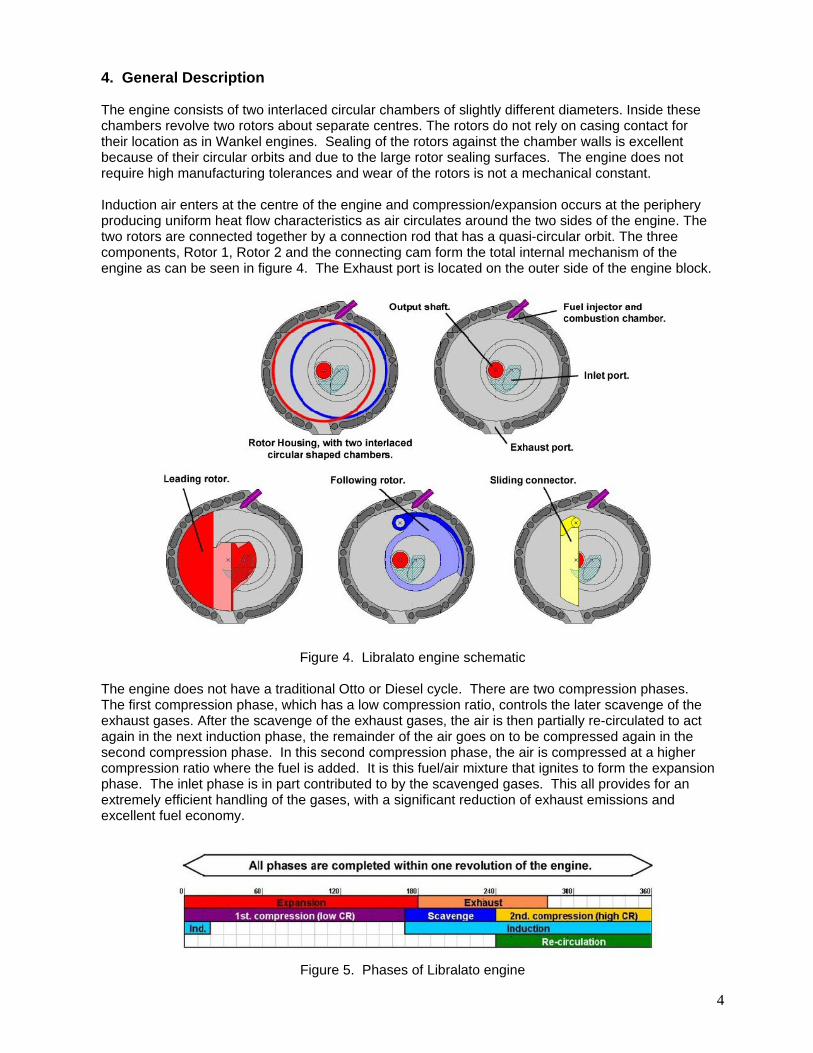
4. General Description The engine consists of two interlaced circular chambers of slightly different diameters. Inside these chambers revolve two rotors about separate centres. The rotors do not rely on casing contact for their location as in Wankel engines. Sealing of the rotors against the chamber walls is excellent because of their circular orbits and due to the large rotor sealing surfaces. The engine does not require high manufacturing tolerances and wear of the rotors is not a mechanical constant. Induction air enters at the centre of the engine and compression/expansion occurs at the periphery producing uniform heat flow characteristics as air circulates around the two sides of the engine. The two rotors are connected together by a connection rod that has a quasi-circular orbit. The three components, Rotor 1, Rotor 2 and the connecting cam form the total internal mechanism of the engine as can be seen in figure 4. The Exhaust port is located on the outer side of the engine block.
Figure 4. Libralato engine schematic The engine does not have a traditional Otto or Diesel cycle. There are two compression phases. The first compression phase, which has a low compression ratio, controls the later scavenge of the exhaust gases. After the scavenge of the exhaust gases, the air is then partially re-circulated to act again in the next induction phase, the remainder of the air goes on to be compressed again in the second compression phase. In this second compression phase, the air is compressed at a higher compression ratio where the fuel is added. It is this fuel/air mixture that ignites to form the expansion phase. The inlet phase is in part contributed to by the scavenged gases. This all provides for an extremely efficient handling of the gases, with a significant reduction of exhaust emissions and excellent fuel economy.
Figure 5. Phases of Libralato engine
5
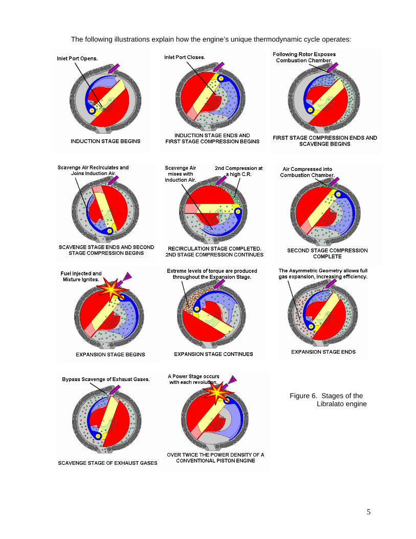
The following illustrations explain how the engine’s unique thermodynamic cycle operates:
Figure 4. Phases of Libralato engine Figure 6. Stages of the
Libralato engine

6
5. Efficiency Gains There are a number of substantial sources of efficiency gains present due to the manner in which the gases are handled and the forces are transmitted to the output shaft. Efficiency Gain 1: The expansion volume of the Libralato engine is larger than the compression volume, allowing complete expansion of the gases (Atkinson Cycle). Thermodynamically this allows the maximum amount of chemical energy from the fuel to be converted into mechanical work. Thermodynamically, the Libralato engine is calculated to produce a 5.5% increase in efficiency over conventional 4 stroke piston engines. Efficiency Gain 2: The force created by the combustion is directly placed on the output shaft instead of a connecting rod – rod bearing – crankshaft setup, which result in energy losses. In piston engines the piston is at the end of the cylinder when the ignition occurs, therefore having a fully extended connecting rod does not permit the configuration to transfer torque immediately to the crankshaft. Efficiency Gain 3: As the pressure of the combustion gas decreases, the working surface area of the leading rotor increases and therefore a fairly constant torque is placed on the output shaft over 150 degrees. Since the effective combustion cycle is 150 degrees per revolution, two engines could be used in series to result in 300 degrees of constant torque output. This setup would greatly reduce the number of cylinders needed to perform the same work with conventional piston technology. Efficiency Gain 4: There is relatively uniform thermal dispersion across the entire engine due to the constant recirculation of air, and the mechanical interaction between the two sides. This uniform thermal dispersion implies the need for less cooling of the hotter side of the engine (which is an issue in the Wankel engine). Since engine cooling is a process that taps into the combustion energy source, uniform temperature dispersion would reduce this loss. Efficiency Gain 5: Due to constant recirculation of air inside the engine there is less time required for engine heat up during the start up and therefore less time is needed until optimum efficiency temperatures are reached by the engine. Efficiency Gain 6: Larger entry and exit ports for the entering and exiting gases substantially reduce air friction. Air friction normally dampens the speed of the moving components and therefore represents frictional losses in the system. Having very large exhaust ports and entry ports substantially reduces these air frictions. Efficiency Gain 7: Due to the compact design, fewer components, and a combustion phase in every 360 rotation, the engine will be both lighter and higher performing than 4 stroke technology. This considerable reduction in weight will correspond to greater fuel efficiency due to reduced vehicle weight. Efficiency Gain 8: Due to the two counterbalancing rotors, the equivalent weight distribution/ centre of gravity is very good and does not require substantial weights to reduce vibration.
Figure 7. Atkinson Cycle

7
6. Fuel and Efficiency The Libralato engine will function well with any fuel, and the concepts already mentioned would apply equally well to whichever fuel is used. A conventional small diesel engine is up to about 40% efficient, this compares with about 30% efficiency for a petrol engine. It is calculated that the Libralato engine can attain about 50% efficiency using diesel as a fuel. This approaches the efficiency range of current fuel cell technology at higher load levels, at a tiny fraction of the cost. Diesel fuel is relatively inexpensive, has a well established supply infrastructure and does not present the problems of transportation and storage associated with fuels like hydrogen. Use of biodiesel (and other biofuels) is becoming increasingly common. The EC Renewable Transport Fuels Obligation requires member states to increase the share of biofuels in surface transport applications to approx 5.75% by 2010 and blends of B20 (20% biodiesel) are expected to become fairly commonplace within the next decade or so. The fuel characteristics of B20 are not significantly different from diesel fuel and the advantages of higher engine efficiency and higher fuel density (hence increased mpg) are added to by typical reductions of 10% in CO2 emissions on a life cycle analysis (see CONCAWE 2005).
Figure 8. Comparative efficiency of Libralato engine (fixed rpm) 7. Air Scavenge and Emissions The regulated emissions for new engines are hydrocarbons (HC), carbon monoxide (CO), nitrogen oxides (NOx) and particulate matter (PM). Unlike petrol engines, diesel engines do not have much trouble meeting HC and CO standards. Traditionally the problem emissions have been NOx and PM. With the unique air scavenge characteristics of the Libralato engine, emission levels from both these sources can be significantly reduced beyond current state of the art diesel engine technology. The first compression phase of the Libralato engine controls the later scavenge of the exhaust gases. This scavenge phase has several functions. Firstly, it helps to oxidise the exhaust gases more fully. Secondly, it reduces the temperature of the exhaust gases. Thirdly, the scavenge air can be re-circulated within the engine to act again in the induction phase. Finally, it avoids an extra phase for the mechanical expiration of the exhaust gases.

8
Air contains not only oxygen but also mainly nitrogen. During the combustion process of converting hydrocarbons and oxygen into carbon dioxide and water, the nitrogen also tends to react with the oxygen forming nitrogen oxides (NOx). Traditionally exhaust gas recirculation (EGR) has been used as a means of reducing peak temperature during combustion. Since the exhaust gas does not participate in the combustion process it absorbs some of the energy and hence lowers the peak temperature and reduces NOx formation. The pulsed air scavenging of the Libralato engine provides copious amounts of excess air. A high excess air ratio allows a greater use of EGR to further reduce NOx production. The scavenge phase provides a high-velocity air stream and turbulent mixing of the combustion by-products. The increased oxygen concentration further enhances particulate matter (PM) oxidation and helps burn up the PM as they form. Because NOx is formed early in the combustion cycle, adding air later in the cycle does not increase NOx. It is expected that with the amount of excess air almost doubled, that both NOx and PM are reduced simultaneously by about 50%. Since Diesel engines operate at an overall lean fuel-air ratio, they already tend to emit low levels of hydrocarbons (HC) and carbon monoxide (CO). Excess air will however show a further reduction in HC and CO emissions. Because the Libralato engine is based on high excess air capacity it is not sensitive to fuel sulphur content. 8. Product Segmentation Potential applications for the Libralato engine, range from small-scale engines (< 1 kW) to larger engines for e.g. transport applications (>100 kW).
Product segment Examples Needs (Key design criteria)
Small-scale small-scale models Low Weight High power to weight ratio
Portable Chainsaws Brush cutters Leaf blower Hedge trimmers Cut-off saws
Low Weight Low vibration Low noise High power to weight ratio
Stationary Power generators Compressors
Low noise Reliability
Mobile Lawn movers Cultivators Snow throwers
Low noise Low weight High power to weight ratio
Industrial Excavators Skid steer loaders Dumper trucks (< 5 tons)
Light boats Outboard motors Low noise Low pollution
Light vehicles Scooters Motorcycles Snowmobiles
Low noise Low pollution
Road vehicles Cars Racing cars Light trucks
High efficiency Low pollution Reliability
Light airplanes Airplanes Low Weight High power to weight ratio

9
9. Competition
Competitor Characteristics
4-strokes piston engines
Dominant design especially in most of the larger applications, like vehicles. 4-stroke engines are increasingly appearing even in the portable segment. This trend is caused by future gas emissions regulations in EU and USA. An innovative example is the 4-MIX-engine from Stihl. Advantages: lasts longer than two stroke engines, more efficient gas consumption, pollutes less than its counterparts, easy start, less noisy than 2-stroke engine, Disadvantages: more complicated, many more moving parts, less powerful than two stroke engines (for equivalent engine size and weight), more expensive to manufacture.
2-strokes piston engines
Heavily dominant technology in all fuel powered portable tools. Advantages: simple and light design, high power-to-weight ratio (compared to 4-stroke piston engines), low manufacturing costs, operates in any position. Disadvantages : Fuel-inefficient, faster wear and shorter engine life than a 4-stroke due to the lack of a dedicated lubricating system, heavy and unhealthy pollution due to gas/oil mixture, noisy, hot exhaust gases.
Rotary engines (Wankel)
Several car manufacturers such as Citroën, NSU, Mazda and Rolls Royce developed models based on the Wankel engine between 1950 and 1970. During this period, models of motorcycles, airplanes and even chainsaws were powered by this type of rotary engine. Advantages: simple design, few moving parts, high specific power, low vibration. Disadvantages: less efficient than four stroke piston engines, but more than 2-stroke, hot exhaust gases with high monoxide and hydrocarbon prevalence, sensitive to dirt, ignition problems, sealing problems, poor reliability.
The analysis below provides an overview of critical technical advantages Libralato’s engine, compared with competing technologies according to customer's criteria (RPP analysis).
Selecting criteria Assessment of the 3 main competitors
Power-to-weight ratio
Noise level
Vibration level
Efficiency
Pollution
Production cost
Maintenance costs
Reliability
Torque
Number of components
Simple design
Housing volume
Libralato engine 2-stroke piston engine Wankel rotary engine 4-stroke piston engine
Favourable Fair Unfavourable

10
10. Technical Analysis Despite the few moving parts in Libralato engine, the four main components listed in Figure 4 undergo very intricate interactions with each other in order to achieve a combustion cycle with the associated high levels of efficiency. This section is intended to indicate some key design features prior to the “360°technical layout” since they are not obvious and impede the reader from fully understanding Libralato engine. Hidden feature 1: The combustion chamber, containing the spark/glow plug is located behind the path of the two rotors and therefore can not bee seen in the sequence of images presented. The spherical shape of the combustion chamber optimizes the burning of the fuels. Figure 9.
Hidden feature 2: The combustion chamber permits air to pass between the right and left chambers only during a specific point in the cycle. This can be clearly seen in figure 10 as the two rotors move in a counterclockwise direction, the green represents the hidden combustion chamber. Figure 10 A the following rotor does not permit a passage of air to occur through the combustion chamber due to the seal between the following rotor and the engine block that is indicated in red. Figure 10 B the leading rotor and the following rotor have intersecting ends with the combustion chamber and there is an open canal, permitting air to flow from the right chamber to the left chamber. Figure 10 C the leading rotor now does not permit a passage of air to occur since the combustion chamber is isolated by the seal between the leading rotor and the engine block, this seal is indicated in red.
Figure 10. Hidden feature 3: As seen in figure 4 the sliding connector actually does intersect the output shaft; this point creates visual confusion. It is important to note that the output shaft is not a solid separate entity but it is directly connected to the Leading rotor. A square cut is created in the output shaft purposely to seat the sliding connector, as can be seen in figure 11.
Figure 11.

11
Hidden feature 4: As seen in figure 12 a gear is directly mounted on the output shaft. This gear protrudes underneath the engine and its role is to rotate in a synchronous manner with a second gear of equal dimensions. As can be seen in figure 12 C the second gear is connected to a cylinder that has lateral and lower cut-out sections. When the motor completes its combustion phase the cutouts mechanically align themselves with the combustion chamber in order to permit a mechanical outlet for the combusted gases.
Figure 12. Hidden feature 5: In Figure 13 A the expanding chamber is still permitting air to enter the engine through the green highlighted port. In Figure13 B the air entry port is sealed and the compression of this captured air proceeds from Figures 13 B to E. Note that during the compression, the leading rotor and following rotor seal the air in the chamber as indicated by the red seals. In Figure 13 F the pressure of the air is roughly at 3 atmospheric pressures and at this point it is used to extract the combusted gases as explained in “Hidden feature 2”.
Figure 13. Hidden feature 6: Air leaves the engine from the side of the chamber; however fresh air enters the engine through the central part of the engine. The upper face of the leading rotor faces and seals the air inlet port indicated in figure 14, and only allows air in during a specific interval in time prior to the compression of the fresh air.
Figure 14. Hidden feature 7: The sealing of the exhaust gases is an area where other rotary engines have experienced problems. As can be seen in Figure 15 A, the higher pressures are withstood during the combustion stroke by the leading rotor and the housing as indicated in red. Due to the extensive combustion that took place (Atkinson cycle), the exiting pressure will be low and will actually need further pressure at 3 ATM accumulated in the right chamber to push the exhaust out. The necessary pressure needed comes from the right chamber and feeds into the left combustion as indicated in Figure 15 B. As seen in Figure 15 C, once the rotating exhaust port is closed it will just have to seal for a certain amount of pressure as the intake suction begins through the centre of the engine. This sealing does not need to be very strong it just needs to guarantee that there is no back draft of intake air leaving through the exhaust port. Once the following rotor proceeds a few more degrees a strong seal is formed again between the following rotor and the chamber as indicated in red in Figure 15 D.

12
Figure 15. 11. 360° Technical Layout
Due to the complexity in explaining the combustion cycle of the engine a step by step approach will be taken as the engine is rotated in a counter-clockwise direction. The various actions that occur during the full 360°rotation will be described in detail. During the cycle it is important to not make mental references to the piston engine due to the significant differences with this technology. The first image referred to as the 0° position represents the angle that the leading rotor makes with respect to the output shaft. In this state the combustion of the compressed gases has occurred and the two rotors are moving in a counter clockwise direction. The Libralato engine has force output from the very beginning of the cycle; at this state, a regular four stroke piston engine would have the piston almost fully extended up and very little force would be transmitted to the crankshaft (output shaft). Note: The two rotors never touch the chamber because they are fixed on the centre of the axis; therefore they skim the chamber and do not cause wear as is present in the Wankel design. Note: Due to the large surface interaction between the leading and following rotors the sealing is excellent. It is very important to note the force of the combustion gases are placed directly on the face of the leading rotor because the output shaft is directly mounted on the leading rotor. When the combustion cycle starts the working surface area expands after very few degrees of rotation, as is indicated in blue. As the pressure decreases the working surface area expands and therefore provides a fairly constant torque on the rotor. Figure 16.

13
The surface area increases until it reaches approximately 100 degrees from the reference 0° position, as seen in blue. Past 90 degrees this surface distance remains constant until the exhaust phase occurs. Past 100 degrees from the reference 0° position there is considerably lower pressures from the combustion, but the surface it works on is very large, therefore continuous thrust is achieved. At this point in time the combusting air is placed in communication with the exhaust port as is highlighted in red. During the exhaust phase of the gas the combusted residue is almost at atmospheric pressure, this implies that the noise of the engine is very low because the exhaust pressures are very low. All the valves for the gas outtake have been calculated in order to permit low friction associated with the passage of air that is superior to those in a 4 stroke engine. Furthermore there is a very large air invite for the exit of the gas, and the exhaust port rotates in the same direction as the exiting gas which provides perfect synchronization. Since the pressure in the chamber is so low, the pressure built up in the right chamber helps exhaust the remaining gas out. The compressed gas used is fresh and is at 3 atmospheres. The connection between the two sides is achieved through the actual combustion chamber that acts like a bridge. The air that enters the left chamber is very important also because it permits a constant adjustment of the temperature between the two sides, and allows the left chamber to cool down in temperature. As the combusted gases exit the chamber, contemporarily the leading rotor seals off the bridge created by the combustion chamber. The seal is indicated in red. This means that all the gas in the right chamber remains there at atmospheric pressure. The left chamber has fresh gas because the cleaning of the engine has just occurred, therefore inside the engine at this point in time there is only fresh gas since all the combusted gas has been eliminated. The rotating shaft also moves in the same rotational direction as the moving gases during the sealing, this aids in optimizing the exhaust cut off timing. Once the combustion is complete the new phase of air intake occurs as can be seen from the green air intake port. The intake chamber starts from an almost zero volume thereby intrinsically providing a very strong vacuum intake of air through the centre. Note that the air being sucked through the engine centre will be circulating to the left chamber in the following rotation before being used for combustion air. The in take air cools down the inside of the engine. Note that the air is trapped inside the following rotor therefore cooling the part of the engine that has been exposed to the thermal heat of the combustion cycle. The following rotor has just been directly exposed to the combustion and therefore is relatively warm. As the following rotor proceeds it passes very closely to the right section of the engine block therefore dissipating a lot of the heat evenly across the engine. As the following rotor proceeds heat is dissipated to the right part of the engine block. Figure 17.

14
Simultaneously as air is being sucked into the engine the air in the right chamber is being compressed for the next combustion. Furthermore at 280° the intake gas from the centre of the engine is put in communication with the left chamber (all fresh gas) and intake continues until the leading rotor reaches 0°(right after the combustion occurs). Past the 0°mark the intake port is mechanically sealed in order to permit the compression of the air in the right chamber in order to clean the engine once the combustion has taken place.
Just before the last phase that the air is getting compressed into the combustion chamber the fuel injector releases the necessary gas for the combustion. The following rotor creates a mechanical seal between the fuel injector and the actual combustion chamber right after fuel is injected. The following rotor mechanically segregates the injector behind the combustion chamber, and only then would the gas be ignited in order to avoid thermal damage to the injector head as can be seen by the red separation line. As the combustion occurs in the left chamber the entire air intake gets compressed in the right chamber, ready to be used for the cleansing of the exhaust gases. Cooling / Lubrication: Besides the natural cooling that takes place in the engine through the circulation of air, an additional lubrication system has been patented by Ruggero Libralato that consists of an oil system that works inside the sliding connector and is listed in the patents below. This oil passage has the joint function to lubricate and cool the engine in the process. Publication info: WO2004020791 2004-03-11 Publication info: IT1234406 1992-05-18 Publication info: IT1234679 1992-05-26 Publication info: IT1234671 1992-05-26 Figure 18.