lho type hydraulic cylinder - herion - when safety counts€¦ · d e f g h k l 1 l 2 l 3 l 4 l 5 m...
TRANSCRIPT

HERION Systemtechnik GmbHUntere Talstraße 65 D-71263 Weil der Stadt-Merklingen
Tel.: +49 (0) 70 33/30 18-0Fax: + 49 (0) 70 33/ 30 18- 10
Fitting types see specifications Line connection internal thread
per DIN ISO 228/1 Installation position any Damping, available options
- none - adjustable in both end positions
Fluid, available options - hydraulic oil, filtered - water emulsion, filtered
Temperature range [oC]
for hydraulic oil fluid: - 20 bis + 80 for water emulsion fluid: + 4 to+ 50
Static and dynamic operating pressure
min. 1 max. 50
Static testing pressure [bar]
max. 75
Viscosity range cSt [mm2/s] 3 to 300
LZO
LHO type hydraulic cylinder
dual effect Ø 25 - Ø 100 mm
PN [pmax.] = 50 bar Connection dimensions in accordance with CETOP RP 43 P 7501170.05.08.05
Symbol Description
Materials Flange: Steel
(for fluid water emulsion chem. linked.)
Cylinder tube: Steel (for fluid water emulsion chem. linked.)
Piston rod: Stainless steel, 1.4021
Tie rods: Stainless steel, 1.4104
Tie rod nuts: Steel
Seals:1) Perbunan/PTFE
The cylinders are delivered with a basic coat of paint applied.
1) Other seal materials available on request Features
Tie rod style differential cylinder Stroke length adjusted to customer requirements Low stick-slip movement Adjustable damping, options available
Fluid either hydraulic oil or water For accessories, see document 7501132. Equipment options available - Air extraction

2 Subject to design changes 7501170.05.08.05
LZO
Specifications
Fluid Base no. Hydraulic oil Water emulsion
Pis
ton
Ø [
mm
]
Pis
ton
shaf
ts Ø
[m
m]
Line
con
nect
ion
Pis
ton
area
[c
m2 ]
Rin
g ar
ea [c
m2 ]
Dam
ping
di
stan
ce [m
m]
Dam
ping
on
bot
h si
des
No
dam
ping
Bas
ic m
odel
Bas
e at
tach
men
t
Sw
ivel
be
arin
g B
ase
flang
e
Cov
er
flang
e S
per
ical
B
asic
mod
el
Bas
e at
tach
men
t
Sw
ivel
be
arin
g B
ase
flang
e
Cov
er
flang
e S
per
ical
25 10 G 1/8 4.90 4.12 22 43 355 43 362 00 02 04 05 06 07 40 42 44 45 46 4732 12 G 1/8 8.04 6.91 21 43 356 43 363 00 02 04 05 06 07 40 42 44 45 46 4740 16 G 1/4 12.57 10.56 29 43 357 43 364 00 02 04 05 06 07 40 42 44 45 46 4750 20 G 1/4 19.63 16.50 28 43 358 43 365 00 02 04 05 06 07 40 42 44 45 46 4763 20 G 3/8 31.17 28.03 32 43 359 43 366 00 02 04 05 06 07 40 42 44 45 46 4780 25 G 3/8 50.27 45.35 35 43 360 43 367 00 02 04 05 06 07 40 42 44 45 46 47
100 25 G 1/2 78.54 73.63 37 43 361 43 368 00 02 04 05 06 07 40 42 44 45 46 47
Base no. Fluid / fitting method Order example: (see also questionnaire on last page)
Order no.:
43 357 40 .0150
Stroke length [mm] per customer requirement
Dimension drawings
Basic model

LZO
Dimension drawings
Base attachment
Swivel bearing View A
Base flange
Cover flange
Spherical swivel bearing View A
7501170.05.08.05 Subject to design changes 3
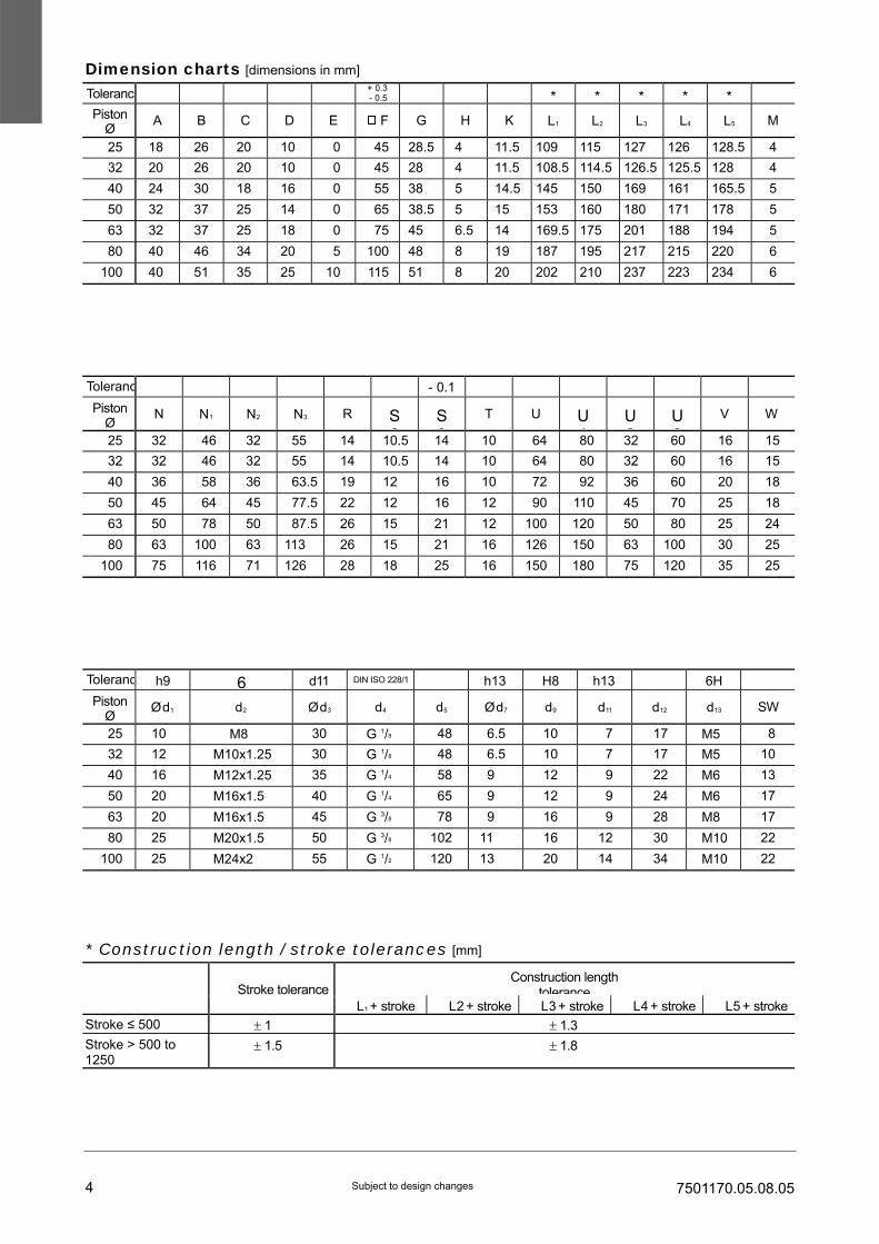
Toleranc + 0.3* * * * *
Piston Ø
A
B
C
D
E
F
G
H
K
L1
L2
L3
L4
L5
M 25 18 26 20 10 0 45 28.5 4 11.5 109 115 127 126 128.5 4 32 20 26 20 10 0 45 28 4 11.5 108.5 114.5 126.5 125.5 128 4 40 24 30 18 16 0 55 38 5 14.5 145 150 169 161 165.5 5 50 32 37 25 14 0 65 38.5 5 15 153 160 180 171 178 5 63 32 37 25 18 0 75 45 6.5 14 169.5 175 201 188 194 5 80 40 46 34 20 5 100 48 8 19 187 195 217 215 220 6
100 40 51 35 25 10 115 51 8 20 202 210 237 223 234 6
LZO
Dimension charts [dimensions in mm] - 0.5
Toleranc - 0.1 Piston
Ø
N
N1
N2
N3
R
S2
S3
T
U
U1
U2
U3
V
W
25 32 46 32 55 14 10.5 14 10 64 80 32 60 16 15 32 32 46 32 55 14 10.5 14 10 64 80 32 60 16 15 40 36 58 36 63.5 19 12 16 10 72 92 36 60 20 18 50 45 64 45 77.5 22 12 16 12 90 110 45 70 25 18 63 50 78 50 87.5 26 15 21 12 100 120 50 80 25 24 80 63 100 63 113 26 15 21 16 126 150 63 100 30 25
100 75 116 71 126 28 18 25 16 150 180 75 120 35 25
Toleranc h9 6 d11 DIN ISO 228/1 h13 H8 h13 6H Piston
Ø
Ø d1
d2
Ø d3
d4
d5
Ø d7
d9
d11
d12
d13
SW
25 10 M8 30 G 1/8 48 6.5 10 7 17 M5 8 32 12 M10x1.25 30 G 1/8 48 6.5 10 7 17 M5 10 40 16 M12x1.25 35 G 1/4 58 9 12 9 22 M6 13 50 20 M16x1.5 40 G 1/4 65 9 12 9 24 M6 17 63 20 M16x1.5 45 G 3/8 78 9 16 9 28 M8 17 80 25 M20x1.5 50 G 3/8 102 11 16 12 30 M10 22
100 25 M24x2 55 G 1/2 120 13 20 14 34 M10 22 * Construction length / stroke tolerances [mm]
Construction length tolerance
Stroke tolerance
L1 + stroke L2 + stroke L3 + stroke L4 + stroke L5 + strokeStroke ≤ 500 ± 1 ± 1.3 Stroke > 500 to 1250
± 1.5 ± 1.8
4 Subject to design changes 7501170.05.08.05
LZO
Order number for LZO type Piston Ø
[mm] Seal material
Perbunan / PTFE 25 11 016 10 32 11 016 11 40 11 016 12 50 11 016 13 63 11 016 14 80 11 016 15
100 11 016 16
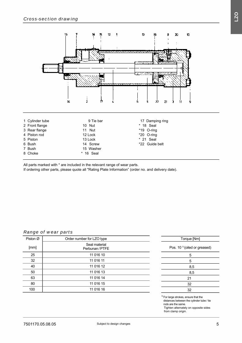
Cross-section drawing
1 Cylinder tube 2 Front flange 3 Rear flange 4 Piston rod 5 Piston 6 Bush 7 Bush 8 Choke
9 Tie bar 10 Nut 11 Nut 12 Lock 13 Lock 14 Screw 15 Washer
* 16 Seal
17 Damping ring * 18 Seal *19 O-ring *20 O-ring * 21 Seal *22 Guide belt
All parts marked with * are included in the relevant range of wear parts. If ordering other parts, please quote all "Rating Plate Information” (order no. and delivery date).
Range of wear parts
Torque [Nm]
Pos. 10 3) (oiled or greased)
5 5 8,5 8,5
21 32 32
3) For large strokes, ensure that the
distances between the cylinder tube / tie rods are the same. Tighten alternately on opposite sides from clamp origin.
7501170.05.08.05 Subject to design changes 5

Ordering notes
Information required when selecting an air extraction system
1. Extraction required in - Front flange - Rear flange - Front and rear flange
2. Position of air extraction screw (position 1 to 4) 3. Installation position of cylinder
= standard position of connection holes and damping choke
View of Piston rod
If you are ordering converted production cylinders or special hydraulic cylinders, please fill in and enclose the questionnaire (7501387) and attach it.
LZO
6 Subject to design changes 7501170.05.08.05