levee settlement problems and improvements study a - item nos. f1.1...levee settlement problems and...
TRANSCRIPT

Levee Settlement Problems and Improvements Study Delta Water Supply Intake Pumping Facility Stockton, CA
August 4, 2016
ATTACHMENT A

Table of Contents Introduction ................................................................................................................................................................... 1
Background .................................................................................................................................................................... 1
Scope of Work ............................................................................................................................................................... 2
Settlement Challenges ................................................................................................................................................... 4
Criticality Ranking ...................................................................................................................................................... 4
Structural ................................................................................................................................................................... 4
Driveways .............................................................................................................................................................. 4
Building ................................................................................................................................................................. 8
Yard ..................................................................................................................................................................... 10
Site Grading ......................................................................................................................................................... 12
Electrical .................................................................................................................................................................. 14
Wastewater, Storm Drainage and Water Utilities................................................................................................... 15
Drainage .............................................................................................................................................................. 15
Sewer System ...................................................................................................................................................... 15
Groundwater Well .............................................................................................................................................. 16
Pipeline .................................................................................................................................................................... 17
Recommended Improvements .................................................................................................................................... 19
Structural ................................................................................................................................................................. 19
Driveways ............................................................................................................................................................ 19
Building ............................................................................................................................................................... 19
Yard ..................................................................................................................................................................... 20
Site Grading ......................................................................................................................................................... 20
Electrical .................................................................................................................................................................. 20
Drainage .................................................................................................................................................................. 22
Drainage .............................................................................................................................................................. 22
Sewer System ...................................................................................................................................................... 23
Well ..................................................................................................................................................................... 23
Pipeline .................................................................................................................................................................... 23
Cost Estimate ............................................................................................................................................................... 25
References ................................................................................................................................................................... 26
hdrinc.com 2365 Iron Point Road, Suite 300, Folsom, CA 95630-8709 (916) 817-4700
i
ATTACHMENT G

Figures Figure 1. Site Location ................................................................................................................................................... 3 Figure 2. Site Aerial ........................................................................................................................................................ 5 Figure 3. West driveway (measurement is representative of and not a complete survey) .......................................... 6 Figure 4. East driveway (measurement is representative and not a complete survey) ................................................ 7 Figure 5. Driveway concrete slab gap (measurement is representative and not a complete survey) .......................... 7 Figure 6. Gaps created between building foundation and surrounding surface (measurement is representative and not a complete survey) .................................................................................................................................................. 8 Figure 7. Representative raised doorway step and separation from landing, east entrance door (measurement is representative and not a complete survey) .................................................................................................................. 9 Figure 8. CMU wall displacement located at the north (measurement is representative of the area and not a complete survey) ......................................................................................................................................................... 10 Figure 9. CMU wall displacement located at the south ............................................................................................... 10 Figure 10. Voids along south of building ..................................................................................................................... 11 Figure 11. Representative voids along south of building (measurement is representative and not a complete survey) ......................................................................................................................................................................... 11 Figure 12. Uneven pavement along north of building ................................................................................................. 12 Figure 13. Crack created in concrete due to displacement, south of building ............................................................ 13 Figure 14. Disconnections in the concrete, south of building ..................................................................................... 13 Figure 15. Location of where the building landing was removed to allow for conduit slack to be extended at north side of building ............................................................................................................................................................ 14 Figure 16. Yard construction repairs - covering plate was removed to allow conduit realignment, various bends were added to the conduit to adjust conduits at the settling ground and pile supported facility; conduits have been left exposed in case of future construction ........................................................................................................ 15 Figure 17. Site well, north of building .......................................................................................................................... 16 Figure 18. Site Well, north of building ......................................................................................................................... 17 Figure 19. 54-inch double expansion joint pipe connection ....................................................................................... 18 Figure 20. 16-inch pipe connection ............................................................................................................................. 18 Figure 21. Crouse-Hinds Expansion/Deflection Couplings (Ref. 1) .............................................................................. 21 Figure 22. Available conduit and max conduit movement manufacture sheet (Ref. 1) .............................................. 22 Figure 23. Flex-Tend double ball joints connector (Ref. 2) .......................................................................................... 24
Tables Table 1. Criticality Ranking ............................................................................................................................................ 4
Appendices Appendix A – Site Fill Appendix B – Meeting Minutes Appendix C – Site Layout Appendix D – Cost Estimate
hdrinc.com 2365 Iron Point Road, Suite 300, Folsom, CA 95630-8709 (916) 817-4700
ii
ATTACHMENT G

Introduction The City of Stockton has contracted with HDR Inc. (HDR) to complete a study at the Delta Water Supply Intake and Pumping Facility (Empire Tract) to assess the impacts of levee settlement at the facility. Improvements at this site can be broken down into two categories: pile supported and non-pile supported. The levee and portions of the facility that are non-pile supported has experienced settlement since the time of construction which resulted in site, structural, electrical, drainage, and pipeline challenges. This technical memorandum (TM) documents the concerns associated with the levee settlement and presents a prioritized list of recommended improvements along with estimated costs. The list of corrections and associated costs will be the basis for the development of Capital Improvement Projects (CIP) to address the issues. Each project will be developed and ranked based on levels of priority discussed within this report.
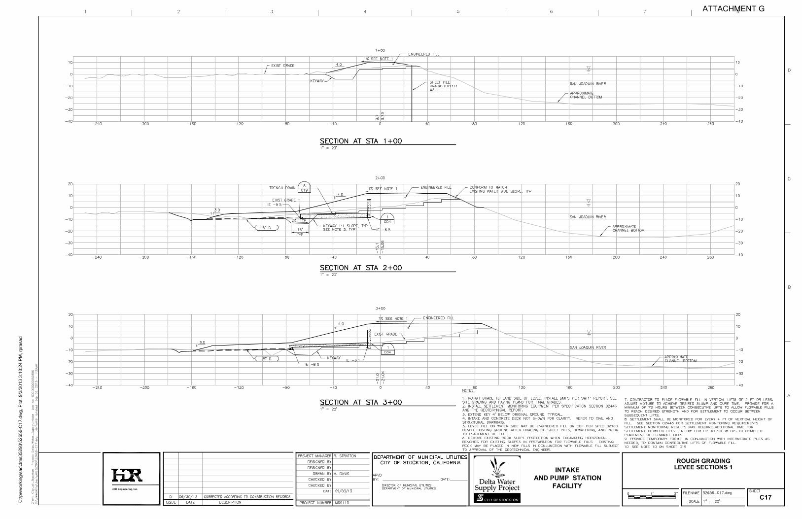
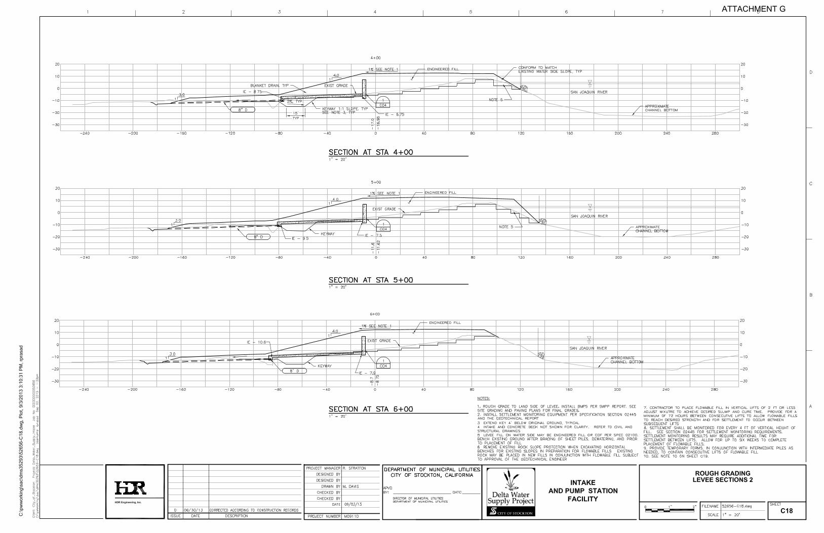
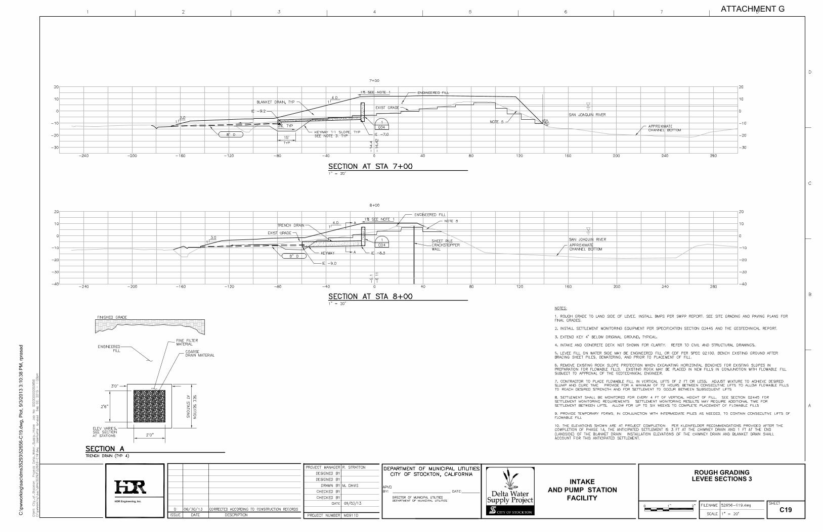
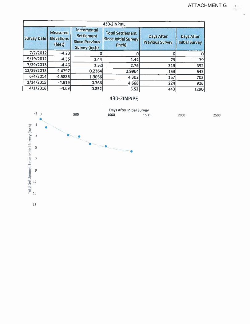
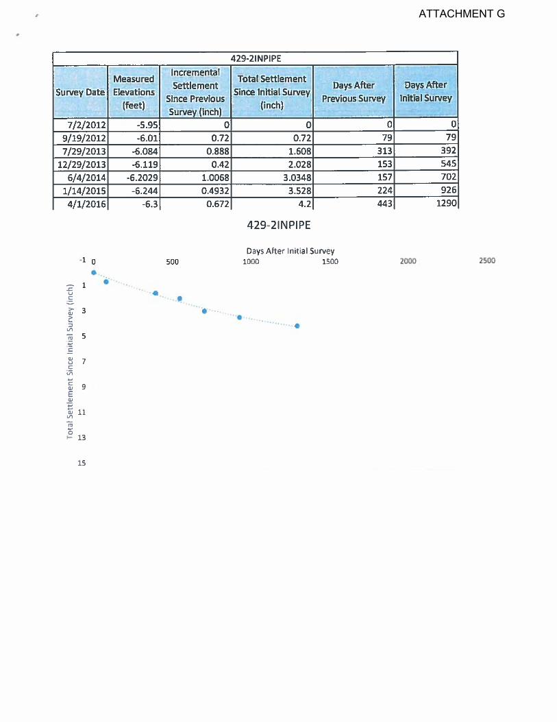
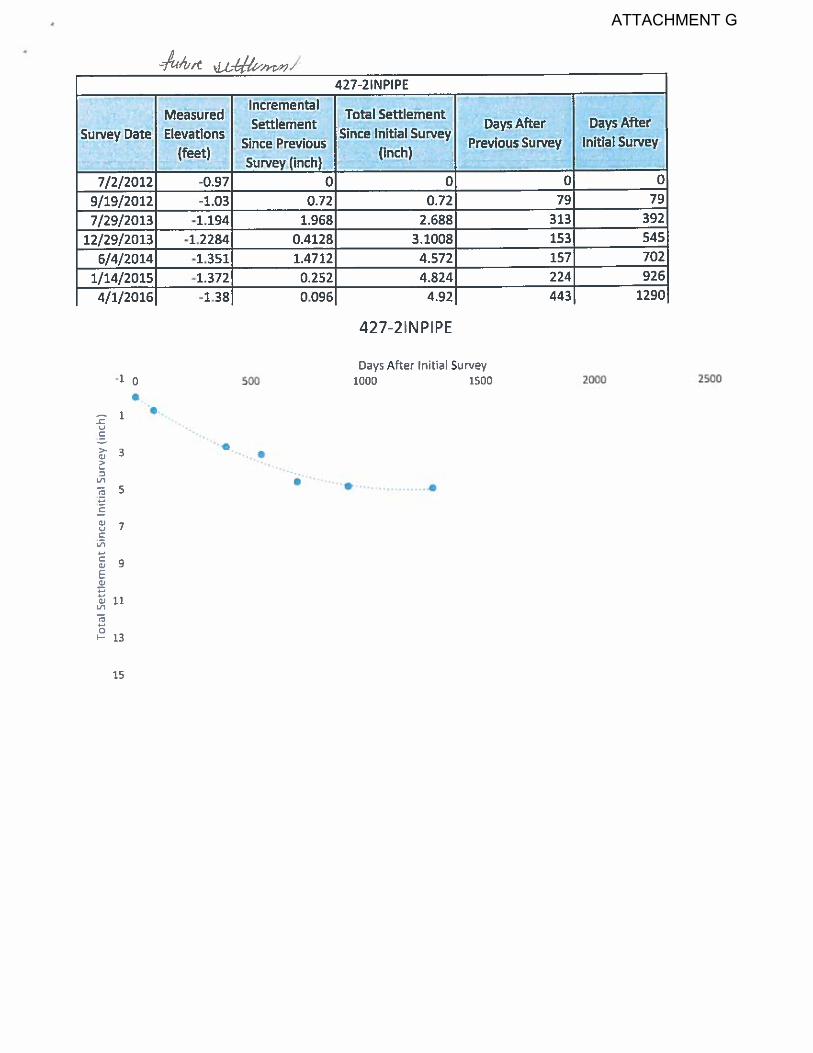
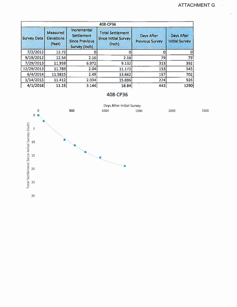
Background The Delta Water Supply Intake Facility is located west of the City of Stockton on the south bank of Empire Tract as shown in Figure 1. The intake facility, constructed from 2009 to 2012, withdraws water from the Sacramento-San Joaquin Delta for treatment and distribution to the City of Stockton Metropolitan Area (COSMA). As noted in the Kleinfelder report dated October 29, 2012 (Ref. 10), the facility was constructed on an existing levee which was raised and widened with engineered fill. Plans showing the fill areas are presented in Appendix A. The existing levee is underlain by a layer of soft peat soils ranging from 10 to 25 feet of thickness at a depth of approximately 10 feet below the crown of the levee. Peat soils are very compressible under load and have low strength. The pre-construction geotechnical report prepared by Kleinfelder dated June 30, 2009 (Ref.9) discussed the soil conditions and expected settlement for the planned widening and raising of the height of the levee. Additionally, a post construction geotechnical letter prepared by Kleinfelder in 2012 (Ref. 10) includes an assessment of the measured settlement through 2012 and related recommendations. Since the completion of construction in 2012, vertical displacement has been observed in the areas not supported by piles. Site elevations have been collected through out the site to monitor the displacement from the construction date to April 4, 2016. Based on the projected displacement, Kleinfelder (Ref. 8) estimated that the site secondary settlement would result in a future settlement of approximately 1 to 1.5 inches, see Appendix B.
The settlement is most noticeable at the boundary areas that are immediately next to the pile supported improvements. Although settlement has slowed, this post construction condition has raised concerns of potential stress induced deformation in the raw water pipeline located in the levee and other impacts to facility operation due to the differential settlement caused by the compressed peat soil burdened by the weight of engineered fill associated with raising and widening the levee. Critical components such as the main pump station building, wet well, and approach ramps are pile supported and have experienced minimal settlement.
hdrinc.com 2365 Iron Point Road, Suite 300, Folsom, CA 95630-8709
(916) 817-4700 1
ATTACHMENT G

Scope of Work HDR discussed the settlement challenges at the site with City of Stockton staff, reviewed geotechnical reports and as-built drawings and performed a site visit on May 14, 2015 to assess the magnitude and impacts of settlement on the facility. The levee settlement monitoring technical memorandum report by HDR (Ref. 6) dated February 12, 2015 was considered when analyzing the post-construction rate and extent of settlement.
The site, structural, drainage, pipelines, and electrical components that have experienced problems due to settlement are identified herein. Problems associated with settlement of the levee alongside the existing pile supported structures that have not settled are documented and assessed. Each reported problem was individually evaluated to determine necessary corrections and improvements. Corrective actions were prioritized depending on the criticality and priority of the system, urgency of repairs and cost was determined for implementation of recommended improvements.
hdrinc.com 2365 Iron Point Road, Suite 300, Folsom, CA 95630-8709 (916) 817-4700
2
ATTACHMENT G

Delta Water Supply Intake Facility
Figure 1. Site Location
hdrinc.com 2365 Iron Point Road, Suite 300, Folsom, CA 95630-8709 (916) 817-4700
3
ATTACHMENT G

Settlement Challenges Major components such as the main pumping station building, wet well, and approach ramps are pile supported and have not experienced significant settlement. However, the non-pile supported levee and selected improvements within the site are experiencing settlement that has resulted in the various problems listed below. The problems are most pronounced in the boundary separating pile supported and non-pile supported components of the project. See Appendix C for overall site layout sections through the levee and a photo perspective plan, which cross references photos of deficiencies to physical locations. Measurements provided throughout this report are approximate and are not based on a complete elevation survey.
Criticality Ranking Each problem area was ranked based on a criteria developed considering the criticality of the issue as presented in Table 1. The criticality list is based on the priority for each issue. For example, repairs of the highest priority include corrections to all issues that prevent the pump station facility from functioning properly and providing water to the City of Stockton. Furthermore, it is very important for site safety and security to be maintained to prevent any incidents on the site (Priorities 2 and 3). Although the site settlement rate has decreased, settlement has not completely stopped, therefore items that may cause functionality issues in the future have been ranked as Priority 4. Items that are not currently affecting site functionality are also included in the priority list and are considered for future correction (Priorities 5, 6 and 7). The preliminary construction cost estimate presented in this report delineates improvement costs based on their criticality.
Table 1. Criticality Ranking
Priority Criteria 1. Pump station functionality 2. Safety 3. Security 4. Issues that will lead to future functionality problems 5. Non-functionality issues 6. Aesthetics 7. Of no importance
Structural
Driveways The site includes two pile supported concrete driveways located east and west of the pump station building. These driveway sections were intended to provide for smooth transition to the section of the levee that has a chip seal overlay to allow vehicular travel as shown in Figure 2. Both driveways connecting the pile supported concrete area to the levee currently have stepped disconnections at the boundary and grade separation due to the surrounding settlement. The settlement has exposed the concrete and created a grade discontinuity between the levee and the concrete driveway. The severity hdrinc.com 2365 Iron Point Road, Suite 300, Folsom, CA 95630-8709
(916) 817-4700 4
ATTACHMENT G
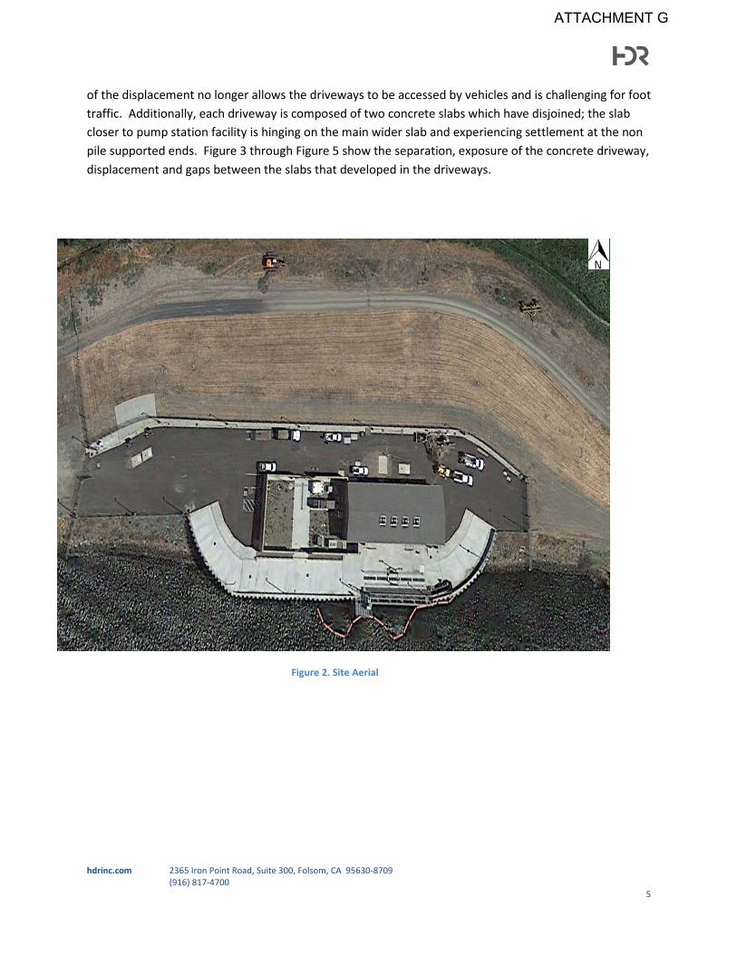
of the displacement no longer allows the driveways to be accessed by vehicles and is challenging for foot traffic. Additionally, each driveway is composed of two concrete slabs which have disjoined; the slab closer to pump station facility is hinging on the main wider slab and experiencing settlement at the non pile supported ends. Figure 3 through Figure 5 show the separation, exposure of the concrete driveway, displacement and gaps between the slabs that developed in the driveways.
Yard
Pump Facility
Figure 2. Site Aerial
West Pile Supported Driveway
East Pile Supported Driveway
hdrinc.com 2365 Iron Point Road, Suite 300, Folsom, CA 95630-8709 (916) 817-4700
5
ATTACHMENT G

Figure 3. West driveway (measurement is representative of and not a complete survey)
The range of displacement measured at the boundary was approximately 16-18 inches on the west driveway and 12-14 inches on the east driveway.
Priority 2 was assigned to these problems, since repairs will improve safety and accessibility.
16-18 inches Hinging slab
hdrinc.com 2365 Iron Point Road, Suite 300, Folsom, CA 95630-8709 (916) 817-4700
6
ATTACHMENT G

Figure 4. East driveway (measurement is representative and not a complete survey)
Figure 5. Driveway concrete slab gap (measurement is representative and not a complete survey)
7 Inches
12-14 inches
hdrinc.com 2365 Iron Point Road, Suite 300, Folsom, CA 95630-8709 (916) 817-4700
7
ATTACHMENT G

Building The pump station facility was built on pile supported foundation and consequently has experienced minimal settlement. Although the levee settlement has not affected the building’s structural integrity, the exterior has settled and vertically disconnected in places from the building. Localized gaps between the building and the surrounding levee fill have been formed as seen in Figure 6. Additionally, the door stoop grade located along the levee (to south of the pump station building) has dropped lower than the surrounding ground resulting in a large grade differential. The California Building Code allows for a single step of 7 inches; the settlement in this location has exposed a greater step. The resulting drop presents more challenging conditions when there is a need to transport heavy equipment through the doors of the intake pump station facility; not to mention the difficulties to personnel using the doorway. Figure 7 shows the exposed step due to settlement.
Priority 2 was assigned to these problems since they involve Code compliance and improvements to safety.
Figure 6. Gaps created between building foundation and surrounding surface (measurement is representative and not a complete survey)
12 inches
hdrinc.com 2365 Iron Point Road, Suite 300, Folsom, CA 95630-8709 (916) 817-4700
8
ATTACHMENT G
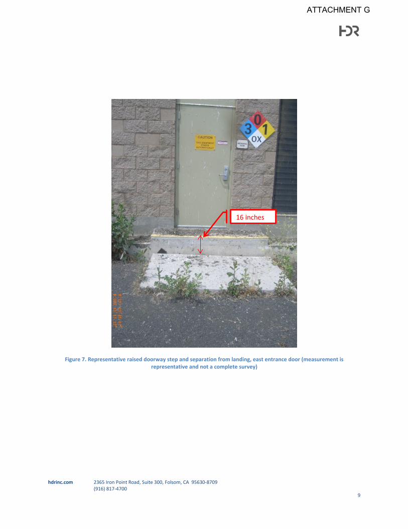
Figure 7. Representative raised doorway step and separation from landing, east entrance door (measurement is representative and not a complete survey)
16 inches
hdrinc.com 2365 Iron Point Road, Suite 300, Folsom, CA 95630-8709 (916) 817-4700
9
ATTACHMENT G

Yard Mechanical and electrical systems and components in the interior of the yard have not presented concerns due to settlement. As shown in Figure 8 the surrounding concrete masonry unit (CMU) wall has settled uniformly, resulting in no visible signs of structural distress or instability. However, in one location the settlement has caused disconnection from the building and resulted in unsafe gaps in between the walls as shown in Figure 9.
Large gaps have been observed in the south yard entrance where large voids developed due to the displacement of the yard and connection to the pile supported concrete driveway, as shown in Figure 10. Figure 11 presents a large unfilled void under the concrete slab driveway which is unsafe.
Due to safety considerations, Priority 2 was assigned to these problems.
Figure 8. CMU wall displacement located at the north (measurement is representative of the area and not a complete survey)
Figure 9. CMU wall displacement located at the south
14 inches
Extent of separation
hdrinc.com 2365 Iron Point Road, Suite 300, Folsom, CA 95630-8709 (916) 817-4700
10
ATTACHMENT G

Figure 10. Voids along south of building
Figure 11. Representative voids along south of building (measurement is representative and not a complete survey)
19 inches
hdrinc.com 2365 Iron Point Road, Suite 300, Folsom, CA 95630-8709 (916) 817-4700
11
ATTACHMENT G

Site Grading Although settlement has been mostly uniform across the entire site, in isolated locations irregular site settlement has resulted in cracking and grade deformations. The deformations have caused areas to protrude and resulted in some cracking of the pile supported concrete near the connection of the concrete and levee. Figure 13 shows uneven pavement along the north side of building caused by hinging on underlying pipe. Figure 12 and Figure 14 depict various locations of the effect of settlement to the site grading, which are considered non-functional issues.
Priority 5 was assigned to these problems as the issues are not critical to facility operations and investment in corrections to these deficiencies can be deferred.
Figure 12. Uneven pavement along north of building
hdrinc.com 2365 Iron Point Road, Suite 300, Folsom, CA 95630-8709 (916) 817-4700
12
ATTACHMENT G
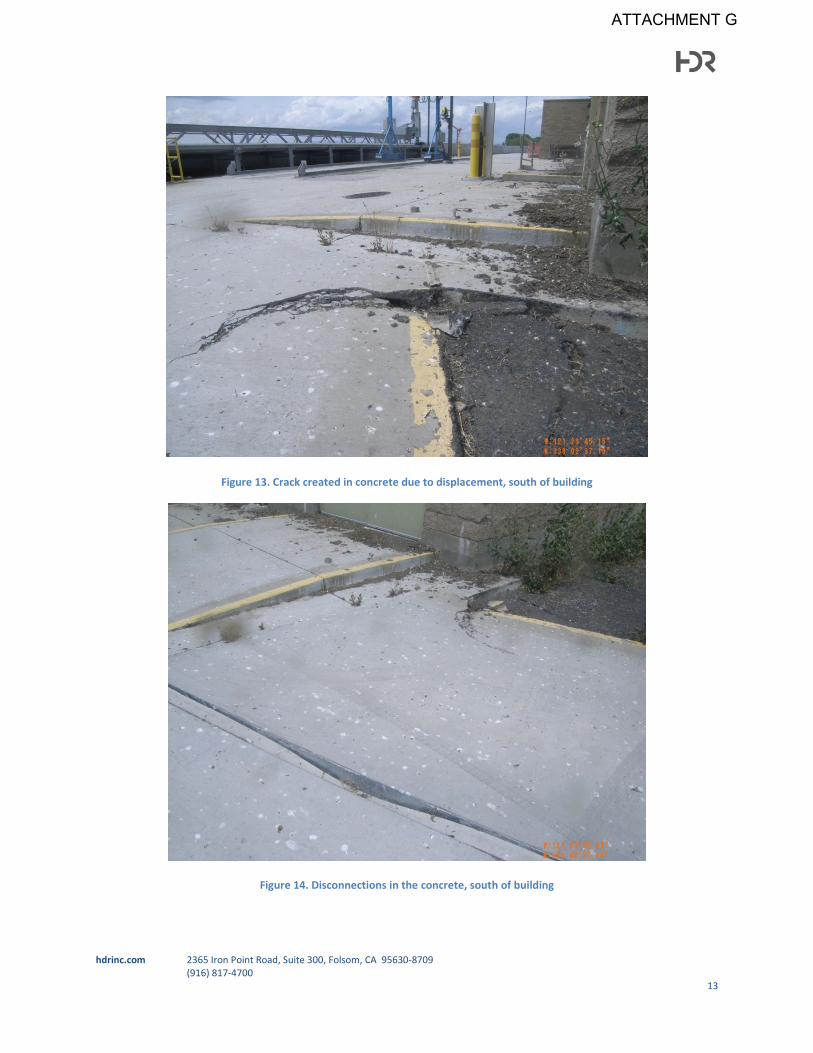
Figure 13. Crack created in concrete due to displacement, south of building
Figure 14. Disconnections in the concrete, south of building
hdrinc.com 2365 Iron Point Road, Suite 300, Folsom, CA 95630-8709 (916) 817-4700
13
ATTACHMENT G
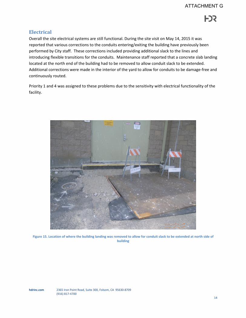
Electrical Overall the site electrical systems are still functional. During the site visit on May 14, 2015 it was reported that various corrections to the conduits entering/exiting the building have previously been performed by City staff. These corrections included providing additional slack to the lines and introducing flexible transitions for the conduits. Maintenance staff reported that a concrete slab landing located at the north end of the building had to be removed to allow conduit slack to be extended. Additional corrections were made in the interior of the yard to allow for conduits to be damage-free and continuously routed.
Priority 1 and 4 was assigned to these problems due to the sensitivity with electrical functionality of the facility.
Figure 15. Location of where the building landing was removed to allow for conduit slack to be extended at north side of building
hdrinc.com 2365 Iron Point Road, Suite 300, Folsom, CA 95630-8709 (916) 817-4700
14
ATTACHMENT G

Figure 16. Yard construction repairs - covering plate was removed to allow conduit realignment, various bends were added to the conduit to adjust conduits at the settling ground and pile supported facility; conduits have been left exposed in case
of future construction
Wastewater, Storm Drainage and Water Utilities The irregular settlement occurring on the site has resulted in some issues in the site sewer, drainage and well water systems.
Drainage The overall site drainage was reported to be functioning correctly and there were no signs of standing water or lack of drainage resulting from settlement at the time of the site visit. Storm drainage is reported to be flowing unobstructed into the river outflow filters. Maintenance staff reported some accumulation of drainage in the vaults and near the well, but they were not concerned since the amount was not significant. Priority 5 was assigned to these problems; repairs are not urgent and could be deferred.
Sewer System The sewer system that discharges into a septic tank on the site has been affected by the site settlement and is no longer operating correctly. The bathroom located in the building is no longer in operation and had to be shut down and temporarily replaced with a portable toilet. The septic line that connects the bathroom to the septic tank experiences back-up flow, which is possibly occurring due to a rise in the yard sewer pipeline that may be hinged by an underlying pipe not allowing for gravitational flow. Priority 5 was assigned to these problems as the portable system can continue to be used and the problem could be deferred to the future.
hdrinc.com 2365 Iron Point Road, Suite 300, Folsom, CA 95630-8709 (916) 817-4700
15
ATTACHMENT G

Groundwater Well The groundwater well located on site is used to supply water for pump station operation. The well is located on the north side of building surrounded by the settling ground. The well and casing are not settling as the depth of the casing bottom extends deeper than the peat soil layer. Settlement of the surrounding ground has resulted in exposure of the well concrete pad as shown in Figure 17 and Figure 18; the pad will need to be replaced. During the site visit, the well was reported to not be operating due to a burnt-out motor, settlement was not the cause. The pump was replaced in the spring of 2016 and is currently working appropriately. Priority 1 was assigned to these problems since reliance on well water is important to the operation of the facility.
Figure 17. Site well, north of building
hdrinc.com 2365 Iron Point Road, Suite 300, Folsom, CA 95630-8709 (916) 817-4700
16
ATTACHMENT G

Figure 18. Site Well, north of building
Pipeline Two major pipe connections are located within the levee. The pipelines are 54-inch and 16-inch pipes with connections in vaults. The original 54-inch pipe flexible joint was replaced in 2013 with an offset flexible joint to allow for additional displacement to the connection due to settlement. Per the site visit in May 2015, no visible damage is affecting the joint as shown in Figure 19. A new 54-inch offset flexible joint is in the process of being installed to allow for additional settlement. The 16-inch pipe connection did not exhibit any visible damage from the settlement as shown in Figure 20. However, a replacement joint for the 16-inch pipeline should be provided to allow for possible future settlement. Additional 54-inch and 16-inch joint replacements may be needed in the future. Priority 1 was assigned to this issue because they directly involve functionality of the facility.
The maximum allowable differential settlement on the 54-inch pipeline is 8.9 inches/100-feet and for the 16-inch pipeline is 28.6 inches/100-feet as reported in the Raw Water Pipeline Differential Settlement – Respond to RD 2029 Question Memo dated March 20, 2013 (Ref. 7). Measurements taken along both pipelines indicate that the actual differential settlement is very small. No action is required for this issue.
hdrinc.com 2365 Iron Point Road, Suite 300, Folsom, CA 95630-8709 (916) 817-4700
17
ATTACHMENT G

Figure 19. 54-inch double expansion joint pipe connection
Figure 20. 16-inch pipe connection
hdrinc.com 2365 Iron Point Road, Suite 300, Folsom, CA 95630-8709 (916) 817-4700
18
ATTACHMENT G
Recommended Improvements Each concern that resulted from the levee settlement has been assessed and recommended improvements are provided below. While the improvements are considered temporary as the levee continues to settle, the corrections may be considered long term if settlement displacement decreases and/or discontinues. Based on settlement comparisons over time, the settlement rate has decreased. In the Levee Settlement Monitoring Technical Memorandum dated February 12, 2015 (Ref.6), the settlement rate along the 54-inch diameter raw water pipeline has decreased from a high of 0.197 inches/day in November, 2012 to 0.0077 inches/day in January, 2015.
Structural
Driveways To address the discontinuity between the pile supported concrete driveway and the levee finish grade, ramps are recommended to provide a smooth transition. It is important that the ramps are designed to provide sufficient rating to allow vehicular and pedestrian traffic while not adding excessive weight on the levee in order to prevent an increase in settlement at installation locations. Ramps constructed of Geofoam (see description below) and covered with asphalt concrete (AC) could be installed to provide a smooth transition for vehicles and pedestrians access while providing the least amount of added weight.
To correct the disjoint of the concrete slabs along the sides of the driveways, the sloping slabs shall be removed and remaining void shall be filled using lightweight fill to restore the grade. A sheet pile should be installed between the levee ground and the road way foundation to protect the adjacent ground and retain the Geofoam. Additionally, a guard rail and an asphaltic concrete curb should be installed to prevent vehicles from driving on to the levee. Instead, vehicles will access the driveways using the ramps described above. Geofoam has been identified as a cost effective lightweight alternative to soil and heavy weight fills which can provide the structural integrity of the driveways. Geofoam is a cellular plastic material which provides strength with the low density, as required by the characteristics of this site, and is sealed to be unaffected by moisture. Although it must be covered with an additional lightweight fill or an aggregate layer, the use of Geofoam provides a low stress since it has a unit weight of 1 to 2 pounds per cubic foot (pcf) in comparison to typical engineered fill with a unit weight of 120 pcf. Additionally, this material is prefabricated in block forms of various standard sizes and easily positioned (Ref. 3). Geofoam is recommended for driveway repairs and to fill in any additional voids created due to settlement.
Building For safety and structural integrity, it is recommended that the vertical door step differentials and horizontal voids created by levee settlement be corrected. For correction of large height differentials created from door threshold to door landing, lightweight fill and aluminum stoops and ramps could be installed. Installation of a ramp will facilitate the door entrance and provide safe access into the building along the levee to the building boundary. Height differentials exceeding 7 inches will require multiple risers (at max of 7 inches per riser) plus a handrail or a stoop and ramp. A stoop at the same elevation as the door threshold is required with both the step(s) and ramp options. hdrinc.com 2365 Iron Point Road, Suite 300, Folsom, CA 95630-8709
(916) 817-4700 19
ATTACHMENT G

New stoops, steps, and ramps should be attached to the building in order to allow them to remain at the same elevation as the building as future differential settlement occurs. Means of attachment may consist of drilled epoxy embedded rods connecting to rebar in the stoops and steps or wedged anchored bolts attaching to aluminum stoops and ramps.
Voids developed by settlement shall be filled and/or sealed using the selected lightweight fill to prevent water or object intrusion and keep structural stability. Stalite has been identified as a cost effective lightweight fill alternative, about 50% of normal weight fills, to soil and heavy weight fills. This material is an expanded slate lightweight aggregate which provides high performance, high strength, durability, and low absorption. Stalite is granular material which is easier to install into small voids (Ref. 4).
Yard Yard improvements are required to maintain site safety. One major safety hazard in the yard is the separation of the CMU wall and the pile supported building along the south side of CMU wall. To repair the separation, a localized section of the wall could be removed and rebuilt. It is estimated that a 3 foot wide section of wall adjacent to the building be removed and rebuilt to cover the gap. The remaining section shall be left in place as it appears to be structurally stable and settling uniformly. The east CMU wall and building connection has not demonstrated significant separation and no modifications are recommended at this time.
The large vertical gaps that have been observed in the south yard entrance, shown in Figure 11, shall be covered to prevent any incidents. Lightweight aluminum plates are recommended to cover the voids. Additionally, a ramp could be added for a safe transition from the pile supported driveway to the yard south entrance to eliminate the large step down created by settlement.
Site Grading To correct the site grading that has resulted from the differential settlement, Geofoam or other approved equal lightweight fill are recommended. The site surfaces in particular areas could be re-graded to regain the smooth transition throughout the site keeping the site slope required for proper storm drainage. Spot locations can be filled with the chosen lightweight fill; fill locations can only be placed outside of the levee prism to maintain the levee integrity. To prevent additional weight on the site, a minimum amount of lightweight fill and removal of existing grade is recommended. Any cracks developed shall be filled or sealed using selected lightweight fill or sealant that will provide cohesiveness and weather protection to cracks.
Results of the latest survey have shown that elevations throughout the levee remained approximately 4 feet higher than the elevation of the surrounding levee of Empire Tract. Geofoam or other approved equal lightweight fill shall be used to minimize future settlement.
Electrical During the site visit performed on May 14, 2015, buried conduits were not inspected. It is recommended that conduits that may be jeopardized by site settlement be corrected to assure site functionality. Based on site plans, approximately 10 conduits are crossing through the pile supported
hdrinc.com 2365 Iron Point Road, Suite 300, Folsom, CA 95630-8709 (916) 817-4700
20
ATTACHMENT G

area and the settling levee and are at risk due to the differential elevation caused by settlement. At locations where the buried conductors have been affected by the settlement, conduit expansion and deflection couplings should be installed. Once couplings have been installed all exposed conduits shall be covered for safety. Alternative improvements may include lightweight flexible backfill around new buried couplings to minimize restriction for movement of the pipe due to further settlement. Conduit expansion and deflection couplings manufactured by Course Hinds have been identified as a candidate to provide the flexibility required for settlement and a water-tight connection. The deflection couplings protect conduit wiring system from damage that may result from axial expansion and contraction up to ¾ inch and angular or parallel misalignment (Ref. 1), as shown in Figure 21.
Figure 21. Crouse-Hinds Expansion/Deflection Couplings (Ref. 1)
Expansion couplings allow from 4 to 8 inches of maximum conduit expansion depending on conduit size. Available conduit size and corresponding maximum conduit movement is presented in Figure 22. Course Hinds conduit expansion and deflection couplings or an approved equal product manufacturer should be selected .
hdrinc.com 2365 Iron Point Road, Suite 300, Folsom, CA 95630-8709 (916) 817-4700
21
ATTACHMENT G

Figure 22. Available conduit and max conduit movement manufacture sheet (Ref. 1)
As of spring 2016, six of the ten couplings identified have been replaced. The remaining four shall be scheduled for replacement. Electrical wiring shall also be replaced. PG&E has been contacted for an inspection and may possibly replace the wiring. Alternatively, a City contractor shall repair the deficiencies. To keep the air conditioning system in service, the wiring was replaced in the spring of 2016.
Drainage
Drainage Overall site drainage was reported to be functional, however storm drains have been re-routed to the depressed area around the wetwell that connects to the river to prevent storm drainage accumulation on site. During site improvements, drainage functionality shall be considered and not be jeopardized by other improvements.
hdrinc.com 2365 Iron Point Road, Suite 300, Folsom, CA 95630-8709 (916) 817-4700
22
ATTACHMENT G
Sewer System In order to put the sewer system back in operation, the sewer pipeline would be required to be reinstalled to provide a slope that will allow gravitational flow. Alternatively, a pump would be required to connect the sanitary facilities to the septic tank. Since needs of the current restroom located in the pump station are limited, it is recommended that the restroom and sewer line be abandoned and permanently replaced with a portable restroom. Maintenance of the portable restroom is to be followed per company guidelines.
Well The well located on the north side of building is critical for pump station operation since it supplies water for pump station cooling and other uses. No current issues have been reported; the pump was repaired in the spring of 2016 and is currently working appropriately. To provide stabilization for the well piping and electrical components the existing concrete pad should be removed and replaced with a lightweight concrete pad adjacent to, but not attached to, the well casing. The remaining void beneath the new lower slab should be filled with approved lightweight fill. The existing piping and electrical components shall be supported with adjustable supports. If necessary, the electrical connections to the well shall be corrected and conduits be replaced with expansion and deflection couplings to prevent future electrical damage. Additional damage to the well that may result from the settlement in the levee shall be corrected accordingly.
Pipeline To maintain site functionality, the pipelines and pipe connections must remain suitable for proper flow. As mentioned in the Pipeline section, two major pipeline components that are of concern are the 54-inch and 16-inch raw water pipelines that extend through the levee and have connections to the pile supported components. Ongoing monitoring of the levee elevation indicates that there is negligible differential settlement along the pipelines within the levee and they are not currently in danger of failure. To accommodate the settlement of the pipeline near the pile supported structure, double heavy duty reinforced rubber expansion joints were installed in vaults. The joint for the 54-inch pipeline is in the process of being replaced with an offset joint completed by Holtz Rubber located in Lodi, California to essentially “reset” the joint for future settlement. While the settlement rate has decreased, there is uncertainty of when settlement will completely stop; therefore, it is recommended that site pipelines remain under periodic inspection. In the event that the recently installed flexible joint on the 54-inch pipeline reaches its maximum allowable deflection, a new offset flexible joint should be measured and installed. The 16-inch pipeline joint is still within its deflection limits, but it should also be replaced with a new offset flexible joint to allow for deflection due to future settlement.
A Flex-Tend flexible expansion joint by EBAA Iron Inc. has also been identified as a long term replacement for the expansion joint connecting the pipelines. The Flex-Tend expansion double ball joint, as shown in Figure 23, would be required for the deflections at this site. Installing a Flex-Tend expansion joint will require existing design modifications including a larger vault. While this type of joint is normally fabricated in sizes up to 48-inch diameter a 54-inch double ball joints can be fabricated as a special order. The lay length of the 48-inch double ball joint is 13.25 feet. Assuming the 54-inch joint is
hdrinc.com 2365 Iron Point Road, Suite 300, Folsom, CA 95630-8709 (916) 817-4700
23
ATTACHMENT G

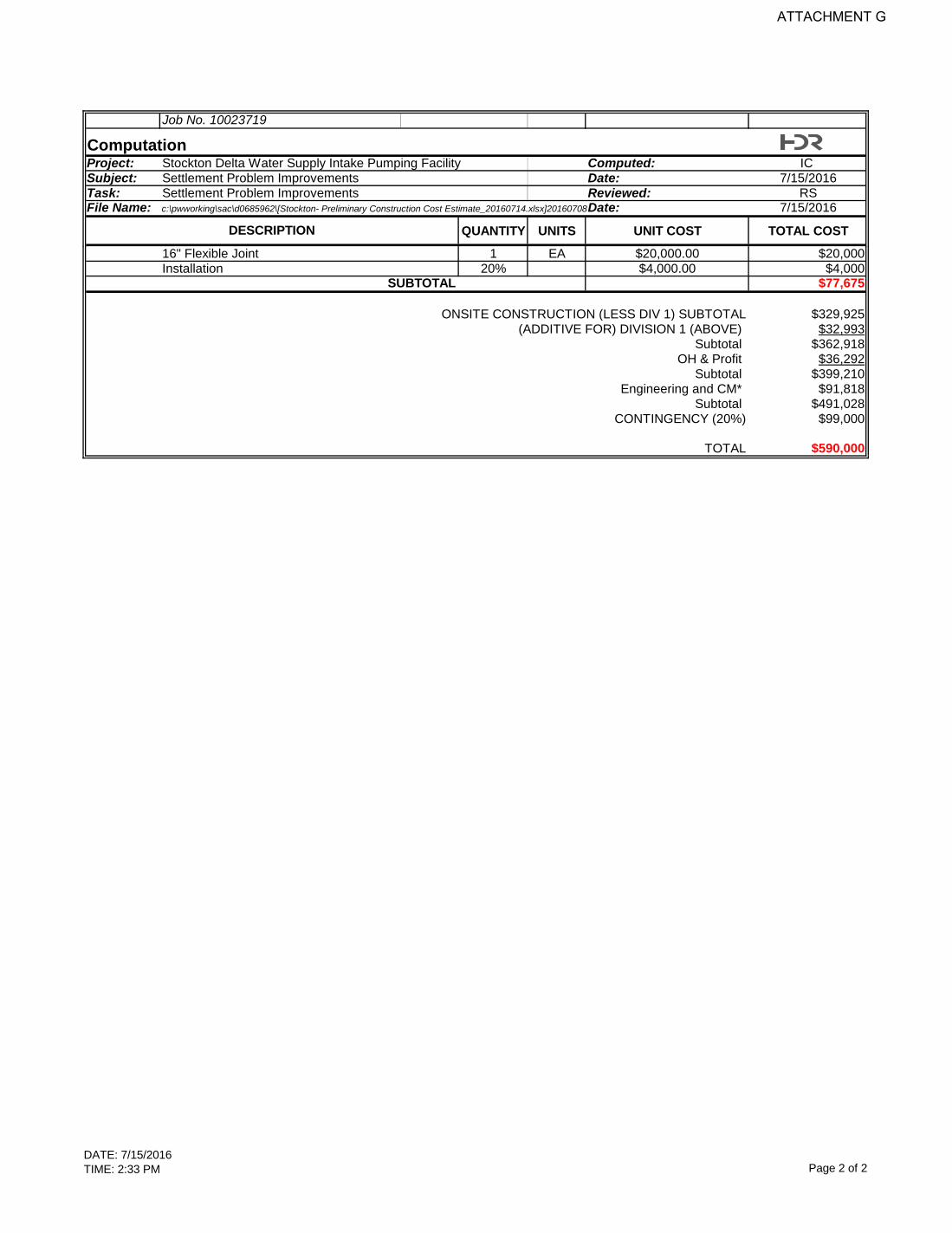
the same length, this would require that the existing 13.5 feet wide by 9.5 feet long vault be replaced with a 13.5 feet wide by 17 feet long vault with a new piping connection. The estimated cost for long term replacements is included in Appendix D.
Figure 23. Flex-Tend double ball joints connector (Ref. 2)
As prevention measure, the pipeline vault walls have been cut down and the cover removed to release lateral pressure and stress previously applied from the concrete walls to the pipes. Replacing the current steel covers with a lighter option, such as fiber glass grated material, may relieve additional pressure for the pipe and joint system. Guardrails or fencing should be installed along the perimeter of the covers to prevent traffic from driving over the covers.
hdrinc.com 2365 Iron Point Road, Suite 300, Folsom, CA 95630-8709 (916) 817-4700
24
ATTACHMENT G

Cost Estimate A preliminary construction cost estimate opinion summary is presented in Appendix D. This cost estimate includes planning level costs for construction, equipment, engineering design and construction management services required for the identified improvements presented in this TM. The cost estimate was based on the following information and assumptions:
• General construction requirements cost including mobilization, demobilization, insurance, and bonds. Bonds are included in this estimate at 10% of total material and labor cost.
• A contingency at 20% of project cost is assumed for this project development. • Engineering and construction management services, including design and engineering support
during construction, are estimated at 23% of the construction and labor cost. • Overhead and Profit was estimated at 15% of the construction and labor cost. • The preliminary costs for the equipment were provided by the recommended manufacturers
and available market prices. Escalation is not included in this estimate but if considered for inclusion and escalation rate of 3% per year is recommended.
hdrinc.com 2365 Iron Point Road, Suite 300, Folsom, CA 95630-8709 (916) 817-4700
25
ATTACHMENT G
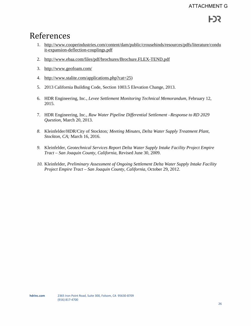
References 1. http://www.cooperindustries.com/content/dam/public/crousehinds/resources/pdfs/literature/condu
it-expansion-deflection-couplings.pdf
2. http://www.ebaa.com/files/pdf/brochures/Brochure.FLEX-TEND.pdf
3. http://www.geofoam.com/
4. http://www.stalite.com/applications.php?cat=25)
5. 2013 California Building Code, Section 1003.5 Elevation Change, 2013.
6. HDR Engineering, Inc., Levee Settlement Monitoring Technical Memorandum, February 12, 2015.
7. HDR Engineering, Inc., Raw Water Pipeline Differential Settlement –Response to RD 2029 Question, March 20, 2013.
8. Kleinfelder/HDR/City of Stockton; Meeting Minutes, Delta Water Supply Treatment Plant, Stockton, CA; March 16, 2016.
9. Kleinfelder, Geotechnical Services Report Delta Water Supply Intake Facility Project Empire Tract – San Joaquin County, California, Revised June 30, 2009.
10. Kleinfelder, Preliminary Assessment of Ongoing Settlement Delta Water Supply Intake Facility Project Empire Tract – San Joaquin County, California, October 29, 2012.
hdrinc.com 2365 Iron Point Road, Suite 300, Folsom, CA 95630-8709 (916) 817-4700
26
ATTACHMENT G

Appendix A - Site Fill
hdrinc.com 2365 Iron Point Road, Suite 300, Folsom, CA 95630-8709 (916) 817-4700
ATTACHMENT G

ATTACHMENT G

ATTACHMENT G

ATTACHMENT G
ATTACHMENT G
ATTACHMENT G
ATTACHMENT G

Appendix B – Meeting Minutes
hdrinc.com 2365 Iron Point Road, Suite 300, Folsom, CA 95630-8709 (916) 817-4700
ATTACHMENT G

Meeting Minutes Project: Delta Water Settlement Improvement - #255178
Subject: Field Visit Notes
Date: Thursday, May 14, 2015
Location: City of Stockton Delta Water Intake Structure
Attendees: Tony Tovar, Tom Frisher, Rich Stratton, Isela Chavez
On Thursday, 5/14/2015 HDR visited the Delta Water Intake Facility in Stockton, CA to observe the affects of the levee settlement to the intake facility. The following was noted;
• Both east and west driveway access ramps have settled, ramps are no longer functional for vehicles to access piled driveways
• CMU wall located around the yard is settling uniformly
• CMU wall has detached from piled building, city engineer requested this be corrected for safety
• Security fence gate located at the east side of facility has been pinched and no longer is functional
• Settlement has resulted in a gap between well platform and ground, city engineer requested this be corrected possibly with fill
• Well is currently not working due to burnt out motor
• Well is required to operate pump station
• City engineer and maintenance personal reported that a landing had to be removed in order to correct conduit leaving the north side of piled building , area was covered with a metal cover
• Vaults containing 16” and 54” valves were open, HDR measured elevations for comparison and analysis for settlement affects
• Settlement of ground around the pile building has caused gaps between ground and building, these area should be sealed to prevent water intrusion
• On the south side (side near river) of the piled building, the area connecting the building and driveway has settled and resulted in a void
• Maintenance personal reported that drainage is working properly , some accumulation occurs at vaults and well area
• The sewer system is currently not working properly , backup has been observed in sewer line connecting bathroom to septic tank
ATTACHMENT G

• Maintenance personal reported that in one event there was possible ground water intrusion into the septic tank and needed to be pumped
• Bathroom is currently out of service, porter potty located on site
• Construction/safety code should be revised for facility
• No problems with fuel tank were reported
• Ground approaching door step has settled resulting in a greater step height on the north side of building
• Ground is uneven on the north side of building
• Priority of settlement improvements was discussed with the city engineer; top priorities includes pumping operation, safety, operation support
ATTACHMENT G

Meeting Minutes Project: Delta Water Supply Intake Pumping Facility
Subject: Levee Settlement Problems and Improvements Study
Date: Monday, May 16, 2016
Location: Delta Water Supply Treatment Plant
Attendees: Rich Stratton, HDR Isela Chavez, HDR Antonio Tovar, Stockton Bob Granberg, Stockton
Eric Houston, Stockton Eric Johnson, Stockton Craig Hall, Kleinfelder Mark, Kleinfelder
• An additional survey has been taken on April 1, 2016 • New survey and additional survey have been analyzed by Kleinfelder Engineering • Kleinfelder Engineering plotted all points and projected future settlement (handout provided);
overall site future settlement expected is 1-1.5 inches based on projection of graph points • Critical site repairs are pipeline, power feed, connection to pipeline, and well • Concern was expressed about the 54” pipe connection at the toe of the levee, TV the line and
exposing to look for cracking or buckling was suggested, deflection angle should be measured • Repairs done/scheduled are:
o Storm drain has been re-routed to well o Vault was have been cut down to release stress on pipe o Flex joint to be replaced for more flexible Holtz joint to allow greater offset o Electrical wires to be extended/replaced, possibly by PG&E and city contractors o 6 of 10 electrical connections have been replaced o Air conditioning wires to be extended, by contractor o Well has been repaired, concrete pad exposed o Restroom to be removed and replaced with porter potty o East gate scheduled to be corrected by city contractors
• Suggestions/repairs to be considered: o Remove concrete pad at well o Cover open vaults with light weight fiberglass grated material for safety o Geofoam to be considered for site grading, gaps, roadway/levee transitions ramp o Geofoam is about 1pcf vs. lightweight fill material that is typically 30-60pcf; lightweight
material was also suggested but has greater weight • Repairs to levee should consider levee requirements such as freeboard, levee integrity,
state/federal regulations
ATTACHMENT G
ATTACHMENT G
ATTACHMENT G

ATTACHMENT G
ATTACHMENT G
ATTACHMENT G

ATTACHMENT G

ATTACHMENT G

ATTACHMENT G

ATTACHMENT G

Appendix C - Site Layout
hdrinc.com 2365 Iron Point Road, Suite 300, Folsom, CA 95630-8709 (916) 817-4700
ATTACHMENT G

ATTACHMENT G

Appendix D – Cost Estimate
hdrinc.com 2365 Iron Point Road, Suite 300, Folsom, CA 95630-8709 (916) 817-4700
ATTACHMENT G

DATE: 7/15/2016TIME: 2:33 PM Page 1 of 2
Job No. 10023719
ComputationProject: Stockton Delta Water Supply Intake Pumping Facility Computed: IC Subject: Settlement Problem Improvements Date: 7/15/2016Task: Settlement Problem Improvements Reviewed: RSFile Name: c:\pwworking\sac\d0685962\[Stockton- Preliminary Construction Cost Estimate_20160714.xlsx]20160708Date: 7/15/2016
QUANTITY UNITS UNIT COST TOTAL COST
GENERAL REQUIREMENTSMobilization 1.50% $4,949Demobilization 1.50% $4,949Division 1 Requirements 3.00% $9,898Bonds, Insurance, etc. 4.00% $13,197
SUBTOTAL $32,993STRUCTURAL/Grading/ PavingDriveways
Light weight fill (Geofoam) 250 CY $75.00 $18,750AC Paving (6 inch AC/12inch AB) 400 SY $40.00 $16,000Installation 20% $3,750.00 $3,750
SUBTOTAL $38,500Building
Aluminum (Pedestrian Rated) Ramps (installation included) 2 EA $10,000.00 $20,000Light weight fill (Stalite) 50 CY $75.00 $3,750AC Paving (6 inch AC/12inch AB) 25 SY $40.00 $1,000Installation 20% $750.00 $750
SUBTOTAL $25,500Yard
CMU wall material 36 SF $22.00 $792Installation (Mason) 20% $158.40 $32Ramp (installation included) 1 EA $8,486.62 $8,487Void Cover (Aluminum) 400 SF $85.00 $34,000Installation 20% $6,800.00 $1,360
SUBTOTAL $44,670Site Grading
Light weight fill (Stalite) 600 CY $75.00 $45,000Installation 25% $11,250.00 $11,250AC Paving (6 inch AC/12inch AB) 450 SY $50.00 $22,500Rough Grading (damaged area) 450 SY $6.00 $2,700Sheet piles along sides of driveways 120 LF $400 $48,000
SUBTOTAL $129,450ELECTRICAL
Expansion/Deflection Conduits Couplings 4 EA $1,600.00 $6,400Installation 20% $1,280.00 $1,280
SUBTOTAL $7,680Site Water & DRAINAGESewer System
Well
Light weight fill 50 CY $75.00 $3,750Concrete Pad (Two- 2'x4') 1 LS $1,200.00 $1,200New adjustable pipe and electrical supports 1 LS $1,500.00 $1,500
SUBTOTAL $6,450Raw Water PIPELINE
Vault Covers (FRP Grating) 215 SF $85.00 $18,275FRP Handrail 2 EA $1,500.00 $3,00054" Flexible Off-set Joint 1 EA $27,000.00 $27,000Installation 20% $5,400.00 $5,400
DESCRIPTION
ATTACHMENT G
DATE: 7/15/2016TIME: 2:33 PM Page 2 of 2
Job No. 10023719
ComputationProject: Stockton Delta Water Supply Intake Pumping Facility Computed: IC Subject: Settlement Problem Improvements Date: 7/15/2016Task: Settlement Problem Improvements Reviewed: RSFile Name: c:\pwworking\sac\d0685962\[Stockton- Preliminary Construction Cost Estimate_20160714.xlsx]20160708Date: 7/15/2016
QUANTITY UNITS UNIT COST TOTAL COSTDESCRIPTION
16" Flexible Joint 1 EA $20,000.00 $20,000Installation 20% $4,000.00 $4,000
SUBTOTAL $77,675
ONSITE CONSTRUCTION (LESS DIV 1) SUBTOTAL $329,925(ADDITIVE FOR) DIVISION 1 (ABOVE) $32,993
Subtotal $362,918OH & Profit $36,292
Subtotal $399,210Engineering and CM* $91,818
Subtotal $491,028CONTINGENCY (20%) $99,000
TOTAL $590,000
ATTACHMENT G

DATE: 7/15/2016TIME: 2:26 PM Page 1 of 1
Job No. 10023719
ComputationProject: Stockton Delta Water Supply Intake Pumping Facility Computed: IC Subject: Settlement Problem Improvements - Long Term Date: 7/15/2016Task: Settlement Problem Improvements -Long Term Reviewed: RSFile Name: c:\pwworking\sac\d0685962\[Stockton- Preliminary Construction Cost Estimate_20160714.xlsx]Long term Date: 7/15/2016
QUANTITY UNITS UNIT COST TOTAL COST
GENERAL REQUIREMENTSMobilization 1.50% $4,536Demobilization 1.50% $4,536Division 1 Requirements 3.00% $9,072Bonds, Insurance, etc. 4.00% $12,096
SUBTOTAL $30,239STRUCTURAL/Grading/ PavingDriveways
Driveway reapir 1 EA $25,000.00 $25,000SUBTOTAL $25,000
Raw Water PIPELINE
EBAA Double Joint 1 EA $200,000 $200,000Vault Cost (1 ft thick walls and floor) 26 CY $1,100 $28,600FRP Grating 81 SF $90 $7,290FRP Handrail 1 LS $1,500 $1,500Installation 20% $40,000 $40,000
SUBTOTAL $277,390
ONSITE CONSTRUCTION (LESS DIV 1) SUBTOTAL $302,390(ADDITIVE FOR) DIVISION 1 (ABOVE) $30,239
Subtotal $332,629OH & Profit $33,263
Subtotal $365,892Engineering and CM* $84,155
Subtotal $450,047CONTINGENCY (20%) $91,000
TOTAL $540,000
DESCRIPTION
ATTACHMENT G