lessons learned: deployment of public sector infrastructure€¦ · 4 lessons learned: deployment...
TRANSCRIPT

1
Lessons Learned: Deploymentof Public Sector Infrastructure
for VII/IntelliDriveSM
Prepared by:
Parsons Brinckerhoff Michigan, Inc.August 2010

2
Table of Contents1.0 Task Introduction ............................................................................................................................... 4
1.1 Interviews ...................................................................................................................................... 4
1.2 Document Organization ................................................................................................................. 5
2.0 IntelliDriveSM Background .................................................................................................................. 5
3.0 VII Deployment History ...................................................................................................................... 7
3.1 USDOT Proof of Concept ................................................................................................................ 7
3.2 New York World Congress .............................................................................................................. 8
3.2.1 Long Island Deployment .......................................................................................................... 9
3.2.2 Manhattan Deployment ........................................................................................................ 10
3.3 Northern California Deployment .................................................................................................. 10
3.4 Road Commission for Oakland County DSRC Deployments ........................................................... 11
4.0 Lessons Learned/Non-Technical ....................................................................................................... 11
4.1 Follow the Systems Engineering Process ...................................................................................... 12
4.2 Project Scope ............................................................................................................................... 13
4.3 The Team ..................................................................................................................................... 15
5.0 Lessons Learned/Technical .............................................................................................................. 17
5.1 In the Field ................................................................................................................................... 17
5.1.1 Cable and Connector Designs ................................................................................................ 17
5.1.2 Maintenance and Operational Need...................................................................................... 18
5.1.3 Integration with Existing Infrastructure ................................................................................. 19
5.1.4 Remote Recovery .................................................................................................................. 20
5.1.5 Field Deployment Design ....................................................................................................... 20
5.2 In the Vehicle ............................................................................................................................... 21
5.2.1 Communication to RSE .......................................................................................................... 21
5.2.2 Standardization ..................................................................................................................... 22
5.3 Backhaul ...................................................................................................................................... 22
5.3.1 Security and Reliability .......................................................................................................... 22
5.3.2 Alternatives Analysis ............................................................................................................. 23
5.4 Enterprise Network Operations Center and Service Delivery Node ............................................... 24
5.4.1 Operations Center ................................................................................................................. 24

3
5.4.2 Standardizing Back Office Operations .................................................................................... 24
5.4.3 System Control ...................................................................................................................... 25
6.0 Conclusion ....................................................................................................................................... 26
7.0 References....................................................................................................................................... 27

4
Lessons Learned: Deployment of PublicSector Infrastructure for VII/IntelliDriveSM
1.0 Task IntroductionParsons Brinckerhoff (PB) was tasked by the Michigan Department of Transportation (MDOT) to compilethis document detailing the lessons learned by various individuals and organizations who have beeninvolved in VII/IntelliDriveSM infrastructure installations, operations, and maintenance. This documentcaptures both the detailed and general lessons learned from early deployments of roadsideinfrastructure, but it does not cover on-board vehicle installations nor does it venture into theapplications realm.
1.1 InterviewsAs part of the evaluation, PB interviewed individuals across the spectrum of VII/ IntelliDriveSM
deployments, including those involved with the U.S. Department of Transportation (US DOT) Proof ofConcept Project, various state demonstration projects, and the New York World Congress deployment.Table 1 shows the participants interviewed, their employers, and the projects they helped deploy.
Table 1: Interview Details
Name Employer DeploymentsGlen Davies Road Commission Oakland County POC and Oakland County, MIWalton Fehr US DOT POCSteve Galgano and John Onis New York City DOT World Congress 2008Greg Larson Caltrans VII CaliforniaJustin McNew Kapsch TrafficCom POC, World Congress 2008,
VII CaliforniaJim Misener PATH – Berkley VII CaliforniaFrank Perry Booz Allen Hamilton POCEmilio Sosa and Richard Lockwood New York State DOT World Congress 2008Jeris White Noblis POC
Some interviews were conducted in person, and some were conducted via telephone. In all instances, ageneral introduction of the task was provided verbally to the interviewee at the onset of the interview,providing them with an overview of our scope and allowing them to focus their answers. Specificquestions within the interviews were targeted toward that individual candidate’s experiences, althoughthe comments in this report are an assemblage and not attributed to any one individual.

5
1.2 Document OrganizationSection 2—IntelliDriveSM Background—Provides general information about IntelliDriveSM
Section 3—VII Deployment History—Discusses the most prominent deployments in brief detail
Section 4—Lessons Learned/Non-Technical—Reviews a variety of feedback related to non-technicalissues, such as program management, concept of operations, and team communication
Section 5—Lessons Learned/Technical—Includes knowledge gained in the field and issues related tobackhaul/back office
Section 6—Conclusion—Presents a closing summary of the lessons learned.
2.0 IntelliDriveSM BackgroundIntelliDriveSM is a suite of technologies and applications that use wireless communication standards toprovide connectivity that can deliver transformational safety, mobility, and environmentalimprovements in surface transportation (Figure 1). The US DOT and private and public corporationshave researched IntelliDriveSM to determine its potential benefits and costs of deployment. Thismultimodal initiative focuses on three main aspects of connectivity:
Among vehicles—emphasizes applications to enable crash prevention among traveling vehicles
Between vehicles and infrastructure—focuses on enabling safety, mobility, and environmentalbenefits
Among vehicles, infrastructure, and wireless devices—provides continuous real-timeconnectivity to all system users
IntelliDriveSM safety applications can enable vehicles to be connected to a traffic operations centerthrough a range of roadside devices and on-board units. These connected vehicles can use IntelliDriveSM
safety applications to have 360-degree awareness of incidents and hazards that are out of their visiblerange. These types of applications can potentially reduce crashes in common trouble areas, such assharp ramp curves and roadways up ahead that are affected by weather conditions. Vehicle-to-vehiclecommunications can also enable data sharing between connected vehicles and provide informationabout vehicle surroundings, such as the presence of bicyclists and pedestrians in the corridor. Warningscould be provided in more imminent crash situations, such as when a vehicle stops abruptly.
IntelliDriveSM mobility applications can provide a connected, data-rich environment based oninformation transmitted anonymously from thousands of vehicles connected to the transportationsystem. Transportation operation centers and DOT agencies can use the data from vehicles to bettermanage the roadway, including optimizing traffic signals and transit operations and more efficientlydispatch maintenance crews or emergency services.
IntelliDriveSM environmental applications include providing travelers with real-time information abouttraffic congestion and other travel conditions so that motorists can make informed decisions to reduce
6
their impact to the environment. Travelers may opt to avoid congested corridors and use arterialroutes, take public transit, or cancel their trip altogether to be more fuel efficient and eco-friendly.
The US DOT IntelliDriveSM research program fosters advancements in transportation system connectivityin both the public and private sectors. The research focuses on refining the technologies that supportsystems and applications, testing their use in surface transportation, determining actual benefits in thefield, and developing consensus standards that will ensure the interoperability of IntelliDriveSM
applications and system components.
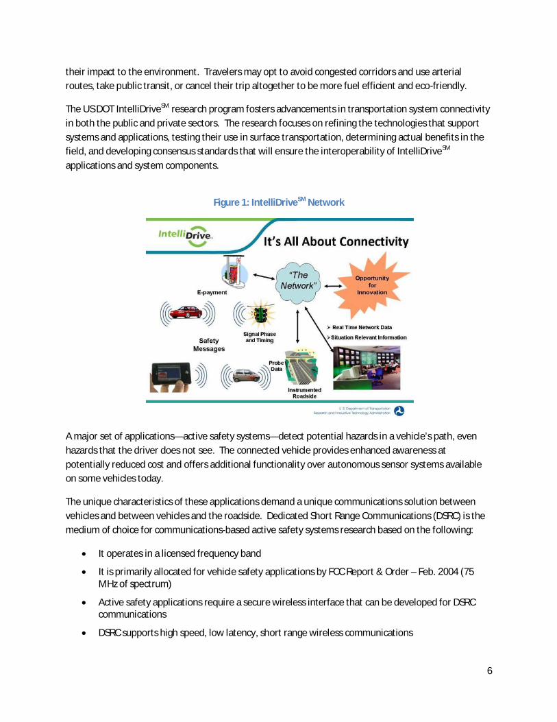
Figure 1: IntelliDriveSM Network
A major set of applications—active safety systems—detect potential hazards in a vehicle’s path, evenhazards that the driver does not see. The connected vehicle provides enhanced awareness atpotentially reduced cost and offers additional functionality over autonomous sensor systems availableon some vehicles today.
The unique characteristics of these applications demand a unique communications solution betweenvehicles and between vehicles and the roadside. Dedicated Short Range Communications (DSRC) is themedium of choice for communications-based active safety systems research based on the following:
It operates in a licensed frequency band
It is primarily allocated for vehicle safety applications by FCC Report & Order – Feb. 2004 (75MHz of spectrum)
Active safety applications require a secure wireless interface that can be developed for DSRCcommunications
DSRC supports high speed, low latency, short range wireless communications

7
The IntelliDriveSM system contains devices that can communicate from equipment located withinparticipating vehicles to roadside equipment (RSE). From that point, data are communicated to severallocations, including the Network Operations Center through preconfigured networking schemes. At theNetwork Operations Center, Advanced Transportation Management Systems (ATMS) and other types of511 traveler information platforms are integrated into a main back office system. A method of datasharing between the vehicle and operations center is thus opened through this communication process.
3.0 VII Deployment HistoryOver the past five years there have been a number of laboratory research projects involvingVII/IntelliDriveSM and at least three major deployments. A brief overview of these is provided below.The lessons learned from these deployments, which are the primary focus of this evaluation, have beencombined and are presented in the subsequent sections.
3.1 USDOT Proof of ConceptIn 2005, the US DOT commissioned a program to test 5.9GHz-based DSRC communications between theroadside and vehicles called the US DOT Proof of Concept (POC). The intent of the POC was to verifythat data can be shared to and from connected vehicles and across an infrastructure of roadside devicesand traffic operations centers in an accurate, timely, and useful manner.
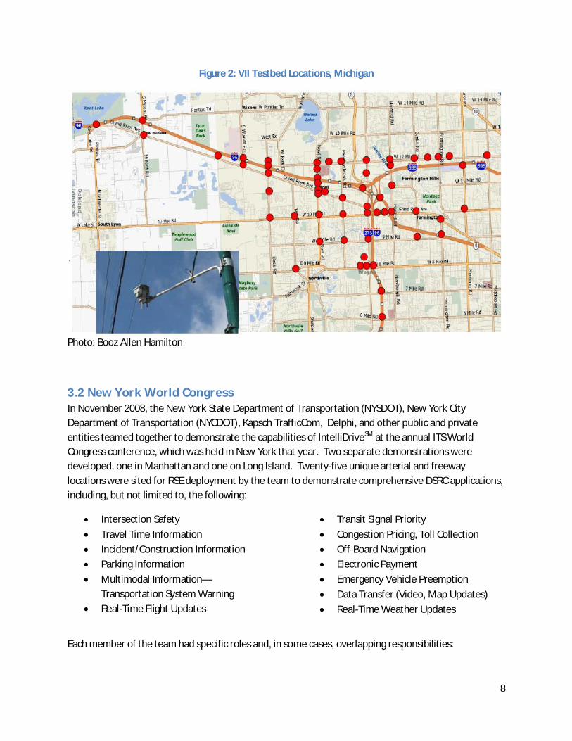
The POC was located in the cities of Novi and Farmington Hills within Oakland County, Michigan (thenorthwest suburbs of the Detroit metropolitan area). In total, 55 RSEs were installed within the twocities covering a 45-square-mile area. A communications network was established with 27 vehiclesconfigured with on-board equipment (OBEs). A small number of applications were also developed andused to test the functionality and performance of the VII communication system. A visual of the POClocations in Michigan is shown in Figure 2.
Several key players were involved in the POC project. Booz Allen Hamilton was the project manager andwas responsible for the design and build of the infrastructure, as well as development of the networkservices. The Road Commission for Oakland County (RCOC) was selected to install the roadside devicesfor 3G and WiMax-enabled back-haul devices, as well as provide the power necessary for the RSEs oncounty-owned traffic signal poles. RCOC also provided personnel to coordinate technical support for theservice providers. Booz Allen Hamilton performed the integration, configuration, and testing of theroadside devices and backhaul methods setup by RCOC. AT&T installed T1s for back-haul at thoseintersections not covered by RCOC. The Michigan Department of Transportation provided contractualservices, coordination, and data exchange.
Two additional parties, Kapsch TrafficCom and Raytheon, were also involved in the POC. KapschTrafficCom (at the time of installation called Technocomm) provided the hardware platform forRaytheon and Booz Allen Hamilton to integrate. Finally, Noblis is now under contract with the US DOTto facilitate transition of the POC to a permanent operations and maintenance contractor. Once thiscontractor is in place, Noblis will remain involved in an advisory capacity.
8
Figure 2: VII Testbed Locations, Michigan
Photo: Booz Allen Hamilton
3.2 New York World CongressIn November 2008, the New York State Department of Transportation (NYSDOT), New York CityDepartment of Transportation (NYCDOT), Kapsch TrafficCom, Delphi, and other public and privateentities teamed together to demonstrate the capabilities of IntelliDriveSM at the annual ITS WorldCongress conference, which was held in New York that year. Two separate demonstrations weredeveloped, one in Manhattan and one on Long Island. Twenty-five unique arterial and freewaylocations were sited for RSE deployment by the team to demonstrate comprehensive DSRC applications,including, but not limited to, the following:
Intersection Safety
Travel Time Information
Incident/Construction Information
Parking Information
Multimodal Information—Transportation System Warning
Real-Time Flight Updates
Transit Signal Priority
Congestion Pricing, Toll Collection
Off-Board Navigation
Electronic Payment
Emergency Vehicle Preemption
Data Transfer (Video, Map Updates)
Real-Time Weather Updates
Each member of the team had specific roles and, in some cases, overlapping responsibilities:

9
NYSDOT— Procurement of RSE radios; software development and installation of ServiceDelivery Node (SDN) in back office; procurement of equipment for backhaul; and coordinationand oversight of ATMS server integration and probe data testing
NYCDOT—Identification and installation of RSE radios; procurement of equipment for backhaul;and coordination and oversight of ATMS server integration and probe data testing
Kapsch TrafficCom—Provision of RSE equipment; oversight of RSE software development; andguidance regarding RSE installation to installers
Delphi—Responsible for OBE system functionality, design, software development, andinteroperability
3.2.1 Long Island DeploymentThe DSRC deployment in Long Island was led by the NYSDOT. Emilio Sosa and his team were responsiblefor the Long Island demonstrations, which included 22 RSE DSRC radios. The team chose nine RSEs to beintegrated with existing traffic signals to demonstrate several arterial applications (signal connectivityfacilitated by Naztec's Apogee software and its compliance with NTICP 1202 version 2). The remaining13 RSEs were deployed on the Long Island Expressway. Locations on the expressway were selectedbased on power availability.
All sites were integrated to have some backhaul method, either through a Code Division Multiple Access(CDMA) 3G data network or through NYSDOT backbone fiber connections. In locations where there wasno available fiber backbone, new conduit and fiber were laid in the ground and necessaryinterconnections were made with existing infrastructure. Signal Phase and Timing (SPaT) details werecollected and distributed across the developed network from the nine locations integrated with existingtraffic signals. The system deployed in Long Island was stable, and all of the devices and coreinfrastructure are still in place today. The NYSDOT developed the service delivery node (SDN) fordeployment in Long Island & Manhattan, which integrated into their existing INFORM system (Figure 3).
Figure 3: NYSDOT INFORM VII System Architecture

10
3.2.2 Manhattan DeploymentThe deployment in Manhattan was led by the NYCDOT. Steve Galgano and his team were responsiblefor the Manhattan demonstrations. The deployment included 20 controllers that were installed in acontinuous route around the ITS World Congress conference centre. The team developed applicationsthat demonstrated all of the similar features from the Long Island demonstration, including travel time,multimodal information, over height/overweight warning, and in-vehicle variable message signs, amongothers.
A primary difference in how the information in Manhattan was distributed to the head office comparedto the Long Island deployment was the use of backhaul methods. The NYCDOT team used the state-owned network that runs on a 3G cellular network similar to that of EVDO (evolution data optimized).
The installation and integration were primarily done by the NYCDOT with help from Kapsch TrafficComto troubleshoot the first few installations.
3.3 Northern California DeploymentIn 2004, Partners for Advanced Transit and Highways (PATH), part of the University of California,Berkeley, worked under contract to the California Department of Transportation (Caltrans), along withother public and private universities and agencies, to design a DSRC deployment and test theapplications of VII in the San Francisco Bay Area and the development of software interfaces betweenthe OBE, RSE, and 511 Message servers.
The partners for the VII deployment in California each had specific roles and, in some cases, overlappingresponsibilities:
PATH—RSE radio identification, software development, and installation
MTC—Procurement of communications equipment for backhaul, coordination and oversight of511 message server integration, and probe data testing
Caltrans—RSE procurement, coordination, and oversight of RSE software development and RSEinstallation
Telvent Farradyne—Backhaul communications, 511 message server integration, and probe datatesting
Daimler Chrysler—OBE system functionality, design, software development, and interoperability
Volkswagen of America—OBE system functionality, design, software development, andinteroperability
Navteq—Integration and interoperability with the Innovative Mobility Showcase (IMS)
11
The first system came online in District 4 (US-101/Ontario). The University of California, Berkley co-installed all of the equipment in partnership with Caltrans staff. The team developed applications forthe deployment to showcase capabilities within VII, such as tolling and integrated transit applications,Cell Phone Automatic Vehicle Locator (AVL), integration with AC Transit (serves the Bay Area), SignalPriority Applications, and the use of SPAT. Mercedes Benz and other auto manufacturers funded theseapplications.
Originally more than 40 RSE devices were procured for this project, but only five are working today inthe field. Many of the RSEs remain in the lab, new and unused. Funding resources for the advancementof IntelliDriveSM in California has come to a halt. Federally funded options are being considered, butthey will require additional stakeholder support to jump start the program in California.
3.4 Road Commission for Oakland County DSRC DeploymentsThe Road Commission for Oakland County (RCOC) has completed several DSRC deployments. Thelargest was a deployment between M-102 (8 Mile Road) and 14 Mile Road along US-24 (Telegraph) inOakland County. In addition, there were earlier deployments of VII for Chrysler World Headquarters inAuburn Hills, Michigan, and a small deployment along I-696 between US-24 (Telegraph) and I-275. TheI-696 deployment is not currently operational.
4.0 Lessons Learned/Non-TechnicalThe biggest lesson from this research effort is that the non-technical issues of a project or program oftendictate its outcome. The following section is focused on issues and lessons learned that did not occurwhile crawling inside a cabinet, up a pole, or inside a computer at an operations center—butnevertheless had a direct impact in many instances on the success or failure of a particular aspect of thedeployment.
Summary of Non-Technical Lessons
Use the Systems Engineering “Vee”
Determine requirements of the entire system prior to deployment
Make sure the project’s scope is clear and consistent over the life of the project
Use the scope to identify appropriate resources needed and roles/responsibilities
Develop project management and controls to mitigate funding issues
Understand the differences between DSRC deployment inspection andtraditional highway design and construction
Choose a project team carefully
Include a good communication plan as part of the project plans
Clearly identify key program champions

12
4.1 Follow the Systems Engineering ProcessSystems engineering reduces the risk of schedule and cost overruns and increases the likelihood that animplementation will meet the users’ needs. Other benefits include the following:
Improved stakeholder participation
More adaptable, resilient systems
Verified functionality and fewer defects
Higher level of reuse from one project to the next
Better documentation
These assertions have been supported by several studies that show good systems engineering can resultin better cost and schedule performance.
Use the Systems Engineering “Vee”. When deploying any kind oftransportation project, especially with technology involved, it isimperative that a defined process be followed throughout theproject duration (see Figure 4). A lack of rigor was a common issuefor all of the VII/IntelliDriveSM deployments, but especially in thecase of the POC. Several interviewees mentioned a lack of rigor/process when it came to the POC as areason why that project struggled at several points. Standard operating procedures were developed,but not all stakeholders were engaged in their development, such as would have been achieved with aConcept of Operations. Functional requirements were proposed, but performance metrics to evaluatewhether the requirements were met were missing in many instances. At least one individual mentioneda lack of independent validation and verification (IV&V) at several important steps in the project.
The most common remark was that the many different parties involved in the project were not “readingfrom the same sheet of music,” thereby resulting in delays and missteps at several points in the effort.
The scope of the POC was broad and intended to test a wide number of variables. One individual madeit clear that, “you can’t test that many things without more rigors in the project management.” In fact,the authors of this report learned that performance requirements for the POC are just now beingdeveloped as part of the hand-off to a permanent contractor. This should have been done before thefirst RSE was deployed.
Determine requirements of the entire system prior to deployment. As IntelliDriveSM deploymentsbecome more widespread, a determination must be made about who will operate and maintain theService Delivery Node SDN. What are the procedures and plans for upgrading the system andperforming routine checks for field equipment connections? Specifying procedures for security andreliability will be critical to the success of the deployment. Specific questions about who will managethe entire operation, the public sector or private sector, must be decided. All of this should be includedin a well documented Concept of Operations and detailed requirements document.
“We weren’t reading from thesame sheet of music—the lack ofproject rigor was troubling.”

13
Figure 4: Systems Engineering “Vee” Model
A thorough Concept of Operations, as defined in the Vee, will force the development of collaborativerequirements, helping reduce or even eliminate conflicts later in the deployment cycle.
Specific to DSRC deployments, one interviewee suggested that the OBE should not be identified as acritical link in the system because of the many variables beyond the control of a public agency. Instead,the government agency should focus its energy on building a robust RSE-SDN-ENOC system and theprivate sector should build OBEs that can work with this system (ENOC = enterprise network operationscenter). This is a common theme in the standards arena where the private sector often prefers that thegovernment agency establish a benchmark or infrastructure system, stick to it, and let the private sectorwork with it. This is a proven and better method than a lengthy collaboration effort where everyonemust agree on a benchmark.
4.2 Project ScopeA project’s scope is the total sum of all of its expected products with their requirements or features.
Make sure the project’s scope is clear and consistent over the life of the project. Throughout theinterview process, several individuals mentioned that the POC, by its scope’s definition, was a researchproject. The original intent as discussed among VII Working Group Members and as presented duringthe early stages, was that the POC was going to be THE test and demonstration that ultimately led to fulldeployment. The expectations among participants were high, and communication with stakeholders didnothing to diminish that expectation. The reality, however, is that the scope evolved into more of aresearch program as it unfolded. And while the key players involved gathered a lot of information

14
throughout the POC deployment, it serves as a poor frame of reference for future deployments todepend upon. More than one individual stated, “the POC was a research project in which the team tookon too much and too complex of a task for a first-time deployment.”
The POC’s scope was also revised about half way through the project because of a personnel change atUS DOT. According to one interviewee, in the end a commercial system was being developed based onthe direction of stakeholders rather than the proof of concept that was originally intended. Anotherinterviewee felt that the mindset for the entire POC was research, and there just wasn’t any long-termO&M vision behind it. Therefore decisions that were made during the design, development, andinstallation phases may not be representative of real-world conditions.
Alternatively, one individual cited that the POC, in its research capacity, provided “a great avenue forcompanies to break into the market and therefore consequent deployments have been more efficientand have gone much smoother.” For example, the New York World Congress deployment benefittedgreatly from lessons learned during the POC, and it could follow that future deployments will continue
to improve as a result of sharing lessons learned.
Use the scope to identify appropriate resources neededand roles/responsibilities. In the case of the POC, theproject scope also defined roles and responsibilities forthe individuals involved. The question arose in multipleinterviews, “Were the correct parties involved in the
deployment?” Many individuals had a similar take on this question, and one individual stated,“according to the definition of the system (POC) the correct parties were involved; but in hindsight theunderlying premise used was wrong and thus more stakeholders should have been involved.” Thatindividual was implying that public agencies as a whole need to be more involved in planning anddeveloping the deployments and providing input regarding which systems and protocols should be inplace for seamless integration.
Develop project management and controls to mitigate funding issues. Because the POC was federallyfunded, the money was distributed in a specific way. Because of some unfortunate procurementcircumstances, it took more than six months for funding to be approved, which required vendors andsuppliers to work at risk during that period. Despite procurement delays, the deployment schedule wasnot altered to account for the delayed budget approval. Some of the private companies struggled tostay within their given budget and ended up losing as much as $1 million on the project because of alack of communication and providing support that was not originally within the scope. For VII California,funding (or lack thereof) has resulted in a temporary shut-down in new installations or maintenance ofexisting field devices. The program continues to develop, but a halt in expansion, according to oneinterviewee, could impact future initiatives.
Understand the differences between DSRC deployment inspection and traditional highway design andconstruction. Another interviewee pointed out that the traditional rule for transportation constructionis that approximately 10 percent of the effort goes toward inspection; however, given the high-tech
“Was it Research or Deployment? ThePOC was a research project in which theteam took on too much and too complexof a task for a first-time deployment.”
15
nature of DSRC deployments, perhaps as much as 20 to 25 percent should be set aside for ampleinspection, testing, and evaluation. This could require a culture shift for some agencies accustomed tosetting aside a set portion of funding for different elements of a project or program.
4.3 The TeamA project team is more than a group of individuals assigned to work on one project. It is a group ofinterdependent individuals who work cooperatively to achieve common project objectives. Theeffectiveness of the project team can make the difference between project success and failure.
Choose a project team carefully. Specific to the POC, one individual stated, “it’s important to have theright team on board. Some of the players had never worked together before, and personalities mighthave gotten in the way of cooperation. Again, without a strong rigorous process, the personalities couldaffect the outcomes of efforts.”
It was acknowledged that the POC integration went “okay but was laced with multiple difficulties due tothe amount of companies and individuals involved in the efforts.” Several individuals mentioned thattheir companies were sometimes forced to work together when in some cases they had competingagendas. The POC had an official integration contractor, but the process didn’t define a specific“integration team” that included all the stakeholders; therefore some key players felt left out of theintegration effort. Individuals interviewed felt that if a team was more formally established,communication and coordination may have gone more smoothly.
One of the successful elements cited several times in regard to VII California was the strength of theteam and how well everyone worked together. More than one individual noted that Caltrans districtpersonnel allowed PATH personnel to have access to signalcabinets and perform installations, a practice unheard ofprior to this effort.
Include a good communication plan as part of the projectplans. One interviewee stated in regard to the POC andother various RCOC installations, “we need to keep thelines of communication open between vendor and the client through the installation process andengage stakeholders early on.” He felt that if the installer engaged the vendor early on, someinstallation issues may have been resolved prior to implementation and would not have required thereplacement of the radios and the extended troubleshooting timeframes. It is also imperative thatregular progress meetings be scheduled. The formation of an integration team might have fosteredsuch a schedule. In many instances, items were not completed in a timely manner causing delays inother parts of the project because of the lack of communication and commitment.
The New York World Congress deployment benefitted from the presence of a strong project team thatcommunicated often and effectively. Although multiple parties were involved, budgets were stretched,and timelines looming—just as with the POC—all parties indicated that the New York deployment wentmuch more smoothly because each team member (and organization) had defined tasks assigned, openlines of communication, and a unified scope of work.
“The POC did not have an officialintegrator team defined…in some casesthere were competing agendas amongthe companies working together.”

16
Clearly identify key program champions. Multiple individuals stated the importance of having aprogram champion who leads the way at the state and national levels. Two specific individuals werementioned as influencing progress: Kirk Steudle (Michigan DOT) and Randy Iwasaki (Caltrans). Thestrong support for VII/IntelliDriveSM at higher levels can often push projects forward, obtain funding foradditional research and development, and promote education on the subject. Strong champions attheir level can also help provide much needed staff resources, buy-in from stakeholders less familiarwith VII/IntelliDriveSM, access to right of way and maintenance of traffic, etc.
Several individuals expressed the need to start educating localagencies now rather than later so they will be prepared whenIntelliDriveSM is ready for implementation on a larger scale. Morechampions at the state level should be cultivated. With therecent departure of Iwasaki, the urgency in California is everpresent. Similarly, Michigan will soon hold a gubernatorialelection that could result in the replacement of Steudle nextyear, thereby removing the second big champion. Once again the question of the Systems Engineeringprocess came up in this regard—a rigorous process could go a long way toward withstanding a change inleadership, but a sloppy process will crumble in the face of champions being replaced.
“A rigorous process can withstandchanges in leadership, but asloppy process will crumble in theface of champions beingreplaced.”

17
5.0 Lessons Learned/TechnicalA number of technical issues related to DSRC deployment have been well documented in other reports,so the intent of this summary is to focus on those issues identified by the interviewees as “critical for thefuture” and, where applicable, to connect non-technical hurdles to technical hurdles.
5.1 In the FieldThe RSE used in the various deployments is a critical element for communicating via DSRC. The RSEdevice is the primary component that sends and receives data from multiple devices within theIntelliDrive SM architecture. The RSE communicates with the OBE and sends and receives informationabout road conditions, traffic conditions, etc. The RSE, also through various backhaul network schemes,translates data to the Network Operations Center (NOC) for operational usage and various systemsinterconnections, thereby enabling the vehicle-to-infrastructure communication. It is intended for, butnot restricted to, installation at a fixed location on the roadway. A majority of the lessons learnedspecific to the RSE can be directly related to a lack of a rigorous Concept of Operations and up-frontprocess planning by all affected participants.
5.1.1 Cable and Connector DesignsDevelop physical interface requirements to reduce installation complexity of the RSE. The Detroit POCteam experienced problems when trying to use different cable types with the three backhaul types (3G,WiMax, and T1). Every backhaul method had a different pin-out on the cable side that required re-engineering the cable. The team eventually standardized the cable so that two of the backhaul methods
Summary of Technical Lessons—In the Field
Develop physical interface requirements to reduce installation complexity ofthe RSE
Ensure ALL coupler/cable connections are weatherproofed and outdoor-rated
Place serviceable parts of the RSE at a height that maintenance staff can reachwithout the need of a bucket truck
Discuss design with local agency and installers to ensure it is appropriate formounting and serviceability of devices unique to that location
Install extra Ethernet connections to allow for maintenance and serviceabilityof field equipment
Evaluate conduit capacity prior to installation
Investigate conduit contents ahead of time
Inventory of existing controller types before implementation
Provide multiple recovery techniques for RSE designs to minimize down time
Review overall design of RSE field deployment to reduce points ofmaintenance and failure
18
(3G and WiMax) used the same pin-out. At locations where T1 backhaul was used, a jumper connectorcable was required to make the connection. The development of physical interface standards for thevarious communication alternatives can help reduce complexity during installation of the RSE, resultingin increased flexibility and interchangeability between sites.
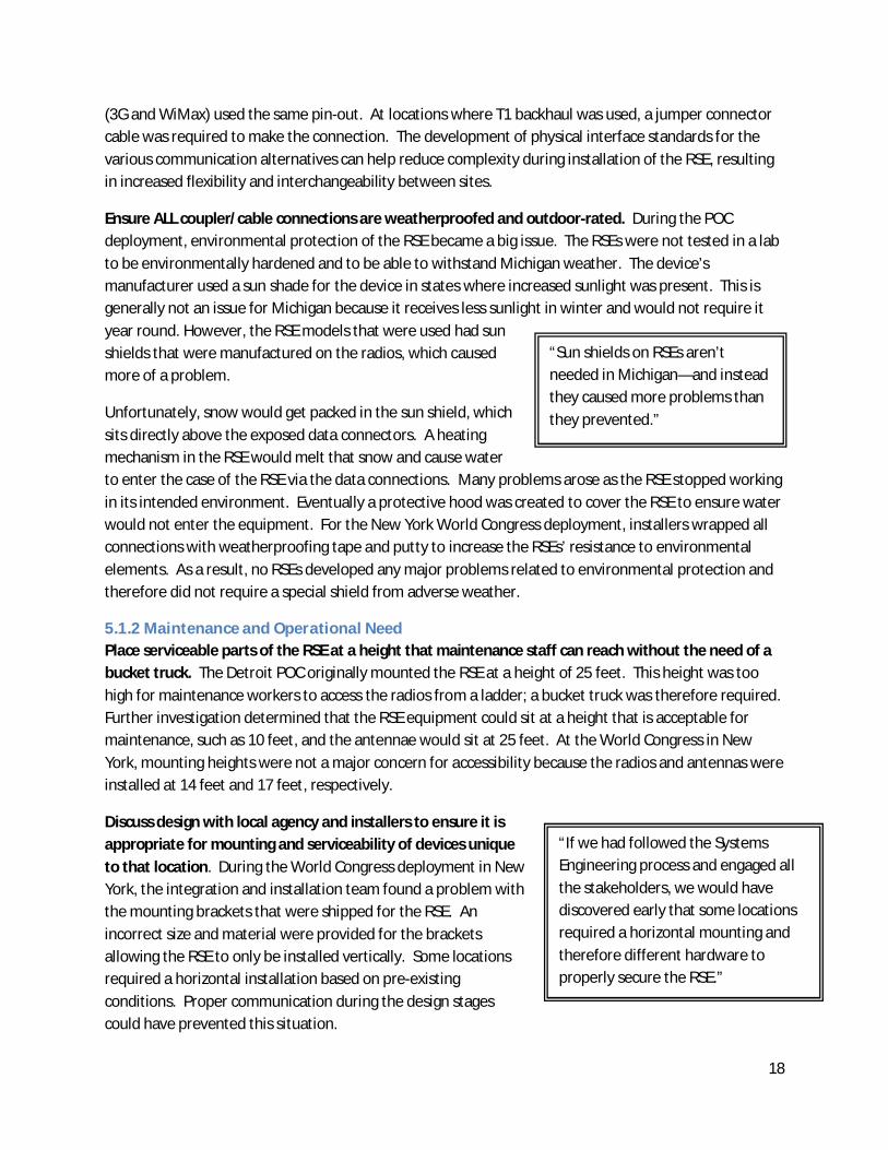
Ensure ALL coupler/cable connections are weatherproofed and outdoor-rated. During the POCdeployment, environmental protection of the RSE became a big issue. The RSEs were not tested in a labto be environmentally hardened and to be able to withstand Michigan weather. The device’smanufacturer used a sun shade for the device in states where increased sunlight was present. This isgenerally not an issue for Michigan because it receives less sunlight in winter and would not require ityear round. However, the RSE models that were used had sunshields that were manufactured on the radios, which causedmore of a problem.
Unfortunately, snow would get packed in the sun shield, whichsits directly above the exposed data connectors. A heatingmechanism in the RSE would melt that snow and cause waterto enter the case of the RSE via the data connections. Many problems arose as the RSE stopped workingin its intended environment. Eventually a protective hood was created to cover the RSE to ensure waterwould not enter the equipment. For the New York World Congress deployment, installers wrapped allconnections with weatherproofing tape and putty to increase the RSEs’ resistance to environmentalelements. As a result, no RSEs developed any major problems related to environmental protection andtherefore did not require a special shield from adverse weather.
5.1.2 Maintenance and Operational NeedPlace serviceable parts of the RSE at a height that maintenance staff can reach without the need of abucket truck. The Detroit POC originally mounted the RSE at a height of 25 feet. This height was toohigh for maintenance workers to access the radios from a ladder; a bucket truck was therefore required.Further investigation determined that the RSE equipment could sit at a height that is acceptable formaintenance, such as 10 feet, and the antennae would sit at 25 feet. At the World Congress in NewYork, mounting heights were not a major concern for accessibility because the radios and antennas wereinstalled at 14 feet and 17 feet, respectively.
Discuss design with local agency and installers to ensure it isappropriate for mounting and serviceability of devices uniqueto that location. During the World Congress deployment in NewYork, the integration and installation team found a problem withthe mounting brackets that were shipped for the RSE. Anincorrect size and material were provided for the bracketsallowing the RSE to only be installed vertically. Some locationsrequired a horizontal installation based on pre-existingconditions. Proper communication during the design stagescould have prevented this situation.
“Sun shields on RSEs aren’tneeded in Michigan—and insteadthey caused more problems thanthey prevented.”
“If we had followed the SystemsEngineering process and engaged allthe stakeholders, we would havediscovered early that some locationsrequired a horizontal mounting andtherefore different hardware toproperly secure the RSE.”

19
Install extra Ethernet connections to allow for maintenance and serviceability of field equipment.When installing field equipment such as RSEs, extra Ethernet connections should be provided somaintenance workers have an easier way to test and resolve field issues. In the New York deployment,two Ethernet connections were installed at each location; three were installed for locations that wereintegrated with traffic signals. One connection was used for SPAT (traffic signal location); one locationfor network communication; and one was reserved for testing. Technicians did not need to climb up toconduct network/configuration testing at each location because of the Ethernet connection that isaccessible from the ground.
5.1.3 Integration with Existing InfrastructureThis section highlights the need for deployment plans that include location surveys and implementationrequirements.
Evaluate conduit capacity prior to installation. In both the POC and VII California, existinginfrastructure was targeted for use. In many instances, however, the conduit tubes were at or nearcapacity (defined in most instances as one-half full). Because of this, the electricians did not want to pullany more cables through the conduits because they feared damage to both the existing and new cables.Appropriate design work will increase the overall cost (dollars and time) during the planning and designphase, but this could prevent major problems in the future. Unfortunately, additional planning anddesign ultimately might be unable to overcome the even larger challenge of laying new conduit if thatbecomes necessary because of a lack of real estate, funding, and resources.
Investigate conduit contents ahead of time. Another issue encountered while running the lines is thatsignal wires and power wires cannot be mixed. Several experts that were interviewed point to this as animportant variable in determining cost/benefit analyses. Not only is it difficult to make broadassumptions on conduit capacity, but conduit contents must be known to properly assess whether newconduit must be laid or existing infrastructure can be used. For several installations in VII California,experiments with using fiber optics to run energy to the cabinet were conducted. In the cabinet the
electrical energy was converted to light and then sent tothe controller where it was converted back to electric.This proved very unreliable.
Inventory existing controller types beforeimplementation. New hardware and software for trafficsignals needed to be developed for the New York WorldCongress deployment. The team determined duringdeployment that the legacy electro-mechanical controllers
would not work with the applications. The team used the NEMA TS2 controller because it couldintegrate with the software and had the necessary conformance with NTCIP. This should be noted forfuture deployments as many locations across the country will need to update their signal controllersbefore installing a DSRC network or even individual DSRC sites at signalized intersections. The VIICalifornia team noted the monumental challenge in coordinating an upgrade to signal controllers just inCalifornia . Of the roughly 40,000 signalized intersections in the state, Caltrans owns only about 5,000,
“Not only is it difficult to makeassumptions on conduit capacity, butthe contents must be known toproperly assess whether or not newconduit must be laid or existingconduit can be utilized.”

20
and the rest are owned, operated, and maintained by more than 58 counties and nearly 500 cities. Aprogram to upgrade controllers at that scale is a huge challenge, not to mention the follow-on step ofintegrating DSRC once the new controllers are installed.
5.1.4 Remote RecoveryProvide multiple recovery techniques for RSE designs to minimize down time. The Detroit POC teamnoted some RSEs would occasionally freeze up and require a manual reboot. This reboot was unable tobe completed from the head-end and would require a technician to visit the site every time an RSEwould freeze up. This task became cumbersome as the frequency of occurrences increased.Technicians were sent out every two weeks to reset RSEs. Regression testing for system operation wascompleted in the lab prior to deployment and was left on for eight hours, but a 24/7 test was notcompleted to detect this issue prior to deployment.
To remedy this issue, the group used power modules to reboot theequipment from an office or any location that could remote into thesite. This eliminated the need for technicians to visit each site butdid not permanently fix the problem. Newer designs of RSEequipment should provide multiple recovery techniques to minimizethe amount of time spent in the field and down-time operations.
The New York World Congress deployments did not experience this issue, which leads to an assumptionthat the POC RSEs were early generation devices and the manufacturers may have corrected the biggerproblem. Further bench and field testing would be required to verify this assumption.
5.1.5 Field Deployment DesignReview overall design of RSE field deployment to reduce points of maintenance and failure. The basicRSE field deployment in both the POC and New York installations included five different primarycomponents: RSE computing platform, RSE power supply, terminal server, main power supply, andbackhaul modem. The design was intended to promote the maximum possible uninterrupted operationof RSE-OBE communication should the backhaul or terminal server components fail.
However, some interviewees pointed out that the downside of thisdesign is that there are now five possible points of failure and fivepossible points of ongoing maintenance that could increase O&M costsand resource needs. At least one individual suggested that futuredesigns should re-examine this approach and consider whether a newdesign could still accomplish the goal of maximum up-time for RSE-OBEcommunication while reducing possible points of failure andmaintenance.
“Any system that includes asmany as five points of failureis a system with potentialproblems.”
“RSEs used in New York Cityrequired far less rebootingthan the POC—manufacturers are gettingbetter at this quickly.”

21
5.2 In the VehicleThe OBE communicates with the RSE and is intended for, but not restricted to, installation in or on amotor vehicle. Auto manufacturers and several private and public entities were responsible for theintegration and development of the OBE that resided in all of the test vehicles. Once again, a failure torigorously follow the systems engineering process uncovered a number of key lessons for the future.
5.2.1 Communication to RSEOBE manufacturers and RSE manufacturers should perform factory testing prior to deployment ofdevices. The development of the OBE should be done in a coordinated manner with RSE manufacturersand stakeholders to ensure that all firmware developments and features integrated by each vendormatch. OBE manufacturers need to develop firm requirements to successfully test products prior toshipment. In at least one instance, an interviewee noted that poor communication between responsibleparties led to significantly longer troubleshooting time-frames. Such issues can be reduced whenmanufacturers implement better quality assurance testing requirements. Following the systemsengineering process and developing a strong Concept of Operations would have identified the need toperform such testing and would have included a complete IV&V process.
Algorithms should be developed within the OBE to choose the strongest RSEs for data transmission.The data transmission from OBE to RSE is an important transaction for IntelliDriveSM. The RSEs aredeployed in such a way that there is an overlap in coverage. As test vehicles drive through the corridor,the OBE recognizes multiple RSEs with similar signal strength, giving the OBE a short amount of time tonegotiate which RSE to communicate with. Currently the selection is done solely on signal strength, asthis is typically the first point of communication between devices. This, however, can cause problemswhen overlapping RSE coverage is present. The Detroit POC experienced garbled transmissions anddropped connections as a result of overlapping coverage. The OBE would start to transmit packets withone RSE then quickly switch to another RSE when the signal strength increased, dropping the packetsfrom the first transmission. The OBE should have some algorithms to select the RSE device with thelowest signal-to-noise ratio as well as signal strength. This type of algorithm may reduce the frequentchange in RSE connections. This issue will become increasingly important in situations with closely
Summary of Technical Lessons—In the Vehicle
OBE manufacturers and RSE manufacturers should perform factory testing priorto deployment of devices
Algorithms should be developed within the OBE to choose the strongest RSEs fordata transmission
Vehicle equipment messages should be standardized and additionaldevelopment should be performed

22
spaced intersections and the need for high geographic accuracy needed for intersection collisionavoidance.
In New York, the team was able to modify how the OBE equipment selected the RSE to reduce thefrequent switching issues (ping pong) between multiple RSEs. In general, no issues were encounteredduring the demonstration or deployment. In California, much testing was performed on the OBE,including packet loss, multi-path, and saturation experiments to ensure that problems with RSE overlapdid not occur.
5.2.2 StandardizationVehicle equipment messages should be standardized and additional development should beperformed. At the time of deployment there was a lack of standardization from OEMs as to the type ofmessages the OBE could support. In one case, SPAT messages were unable to be developed forproduction because the devices were unable to understand the messages. All car manufacturers shouldagree on one standardization so parts of the systems can be standardized as well. All OEMs should beable to “talk the same language” so that, in the future, car manufacturers could perform upgrades (andintroduce new applications) based on a standard system.
5.3 BackhaulMultiple types of backhaul methods for DSRC deployment have been tested and successfully proven tobe useful forms of communication between the RSE and the back office. As with lessons in other facetsof the program, specific situations and environments often dictate different solutions, and a rigoroussystems engineering and requirements analysis can document such situations.
5.3.1 Security and ReliabilityUse a licensed frequency band of WiMax to increase reliability and stability of the network. In theDetroit POC, an unlicensed spectrum of WiMax was used for the backhaul communication method at 15locations that provided connectivity at approximately 6Mbps. The throughput realized in the DetroitPOC was able to handle the amount of data flow of current IntelliDriveSM applications withoutexperiencing any latency issues. The fact that it was unlicensed also meant no additional costs.However, unlicensed and unsecure networks are susceptible to attack and interference, hindering thereliability of the IntelliDriveSM system. When considering WiMax as a backhaul solution, the cost of
Summary of Technical Lessons—Backhaul
Use a licensed frequency band of WiMax to increase reliability and stability of thenetwork
Consider security and accessibility implications when choosing a backhaulmethod
Use multiple backhaul methods to provide the best coverage and failureprotection, although this also increases maintenance and support responsibility

23
using a licensed frequency should be factored into the decision matrix against the costs of otherbackhaul methods.
Consider security and accessibility implications when choosing a backhaul method. The NYCDOT useda private city wireless network (3G cellular, EVDO1) for its backhaul, which was attractive from cost(existing infrastructure) and security standpoints since the network was typically restricted to use byemergency vehicles, homeland security, and the NYCDOT.
Unfortunately, that same security benefit resulted in a challenge when partnered companies wanted touse the internet while accessing the network. As a result, only four companies were provided externalaccess to the city’s private network, and four firewalls were put in place to allow the internet to speakwith the radios as required by the application. Because of the sensitivity of the information and thepotential security risk of the information being broadcast on the internet, the NYC team steered clear of2.4 GHz radios, which traditional WiFi resides on.
5.3.2 Alternatives AnalysisUse multiple backhaul methods to provide the best coverage and failure protection, although this alsoincreases maintenance and support responsibility. A direct fiber optic connection can carry a strongsignal over a wide distance (depending on type), resulting in better quality transmission. Fiber cable isless susceptible to breaking when compared to copper and coaxial cable and provides a higher datathroughput as compared to other forms of communication. However, if fiber does not exist it can alsobe the most costly of solutions up front. A thorough alternatives analysis—typically performed as partof the Systems Engineering process—would identify various situations within the specified deploymentenvironment.
For the Long Island deployment, agency personnel wereplanning to install fiber for other ITS devices and were able tocapitalize on the DSRC installation to “kill two birds with onestone.” In most instances, the fiber connection will also beowned, operated, and maintained by the agency as well,eliminating monthly recurring charges and complications withleased facilities. Unfortunately, not all agencies will have theability to provide a direct fiber link (due to limitations in funding,real estate, conduit capacity, etc).
The Long Island deployment also included some 3G backhaul solutions that were extremely reliable, andthanks to a unique existing contract, the team was able to secure these services at an attractive monthlyrate. Not all agencies will have this opportunity, and in some instances, the quoted rates wereextremely unattractive.
The Caltrans/PATH team would have liked to use fiber optics for its backhaul method in California, butlines were not available in the area. T1 lines (leased from Speakeasy) were used, and the PATH teammembers were happy with the connection as it was low latency. The cost, however, can outweigh thebenefit of using T1 lines, running close to $500 per month.
“This isn’t one shoe fits all, thebackhaul method that is optimalin many instances is dictated bythe environment and can beidentified during the analysisphase of the project.”
24
Unlicensed WiMax is attractive from a cost perspective, but there are environmental (line of site) issuesto contend with, as well as interference issues often beyond the agency’s control. The California teamwanted to use the municipal WiFi that was in the planning stages but, unfortunately, that system neverdeployed due to contractual hurdles and VII California team members had to find other backhaulalternatives. Any use of municipal systems should consider the long-term viability of such a program.
5.4 Enterprise Network Operations Center and Service Delivery NodeThe Enterprise Network Operations Center (ENOC) is used by system operators to control and managethe overall network and RSE suite. The Service Delivery Node (SDN) is composed of interfaces to thebackbone (to other SDNs), the backhaul (to RSEs), and the Access Gateway (to network users), routingfunctions to properly direct message traffic and a set of core services.
5.4.1 Operations CenterThis section discusses operations center requirements and their implementation in accordance withthose requirements.
Identify equipment by a static value, such as an intersection ID or some other pre-defined value. Inthe Detroit POC, the ENOC identified the RSE equipment by serial number. However, this can createconfusion when equipment changes. This requires NOC operators and network users to be notified inthe event of a hardware change. During the systems engineering stage, a process should have beenidentified to help identify and track every asset in the field and back office.
Ensure all critical connections are monitored and tracked. Critical operations were implemented to bemonitored by the NOC. An issue arose in the Detroit POC because everything was not being monitored.The intention was that all devices and RSE connections would be monitored via the NOC and that allcritical personnel should have access to the NOC. Accurate and timely record keeping is essential fortracking all equipment and sites. All critical RSE connections (e.g., PDS/AMDS Brokers, SIT Tunnels, etc.)should be monitored via the NOC, and critical personnel should have access to the NOC.
5.4.2 Standardizing Back Office OperationsCreate a standard for IntelliDriveSM components to interconnect to the back office. Very little work hasbeen done to standardize the SDN and funnel information to the back office in a shared way. Eachdemonstration, the Detroit POC, New York ITS World Congress, and Bay Area Test Bed, used a different
Summary of Technical Lessons—ENOC/SDN
Identify equipment by a static value, such as an intersection ID or some otherpre-defined value
Ensure all critical connections are monitored and tracked
Create a standard for IntelliDriveSM components to interconnect to the backoffice
Develop a process flow to clearly identify roles and responsibilities

25
means for developing an SDN. The NYSDOT wrote and developed software for the SDN prior todeployment. There is also no concrete way that has been developed to identify components andinterfaces.
An ideal scenario would be if additional protocols andglobal objects were defined in the NTCIP standard so thatmultiple communicating products for the back office caninteract with one another, thereby eliminating the need forrecurring software development. Software developmentwould be required by vendors but only to interconnect witha standardized system.
In California, automotive companies did not need an SDN because PATH developed its own data serverto output the information. In the Detroit POC, a Booz Allen proprietary system was developed, butwhen the system was put into use in New York too many compatibility problems were discovered.Instead, NYSDOT contractors successfully developed a separate SDN in a relatively short period of time.
Along with creating a standard for SDNs, requirements and performance metrics should be establishedto evaluate how well the system is functioning. The System Engineering Process for ITS Design shouldbe followed for future developments of IntelliDrive so that a full set of user-defined requirements arecreated and test programs are available to validate the main system works. Future deployments ofIntelliDriveSM systems should run through rigorous testing of the SDN with multiple head-endapplications, multiple RSE vendors, and multiple OEM OBE manufacturers.
5.4.3 System ControlThis section highlights the need for a Concept of Operations, along with the associated requirements,plans, methods, and procedures.
Develop a process flow to clearly identify roles and responsibilities. In addition to the expectedjurisdictional concerns, questions concerning the control, operation, and maintenance of the system,once deployed, will need to be addressed. These include the following:
1. Who is responsible for the various parts of the system?2. What happens if the backhaul fails?3. Who is in charge maintaining and operating the field equipment once it is installed?4. Who is in charge maintaining and operating the back office equipment once it is installed?5. If an application deals with safety (e.g., collision avoidance, stop time, etc.) who is responsible
(liable) if a crash occurs? What if the system went down?
“IntelliDriveSM can only expand and beconsistent across markets andindividual state DOTs with the creationof a standard followed by all ITSprofessionals and developers.”

26
6.0 ConclusionThe lessons learned from these interviews provide a wide range of technical and non-technicalsuggestions to be considered. However, it is clear that adherence to a rigorous program managementeffort, relying on the systems engineering process as a guide, will help reduce or eliminate many of thechallenges and hurdles encountered during some of the early IntelliDriveSM deployments. The evolutionof VII/IntelliDriveSM will undoubtedly uncover new challenges, but already we are seeing progress and asincere desire to not repeat mistakes.
The deployment of DSRC is still in its infancy. Many challenges encountered during the Detroit POC, aswell as with VII California and the New York ITS World Congress, are not uncommon in situations wherenew technology is being implemented for the first time. These could, in some instances, be considerednormal growing pains. However, some of the non-technical challenges are definitely within the controlof all parties involved, and it is hoped that some of these lessons are taken into consideration andsincerely addressed for future deployments.

27
7.0 ReferencesBierlein, D. Davies, G. Piotrowicz, G P.E. “Road Commission for Oakland County VII Implementation atthe Local Level – Final Paper.” PDF file.
Davies, Glenn. Personal Interview. 2 Dec. 2009
Federal Highway Administration. “System Engineering Guidebook for ITS v2.0”, Federal HighwayAdministration. 2007. <http://www.fhwa.dot.gov/cadiv/segb/resources/index.htm>
Fehr, Walton. Phone Interview. 25 Jan. 2010
“FINAL REPORT: Vechicle Infrastructure Integration, Proof of Concept, Executive Summary – Integration.”US Department of Transportation. Feb. 2009. PDF file.
Galgano, Steve. Phone Interview. 19 Jan. 2010
IntelliDriveSM Library. US Department of Transportation. <http://www.intellidriveusa.org/library/rept-dsrc-poc.php> Feb. 2010.
Larson, Greg. Phone Interview. 21 Jan. 2010
McNew, Justin. Phone Interview. 4 Jan. 2010
Misner, Jim. Phone Interview. 19 Jan. 2010
“NYSDOT VII Infrastructure, Inform, I495 Test Bed.” NYSDOT.
Nolden, Richard. Phone Interview. 8 Jan. 2010
Onis, John. Phone Interview. 19 Jan. 2010
Perry, Frank. Phone Interview. 6 Jan. 2010
Perry, Frank. “POC/DTE Deployment Lessons Learned.” Booz Allen Hamilton. Detroit, MI. 20 Aug. 2008.
Sosa, Emilio. Phone Interview. 8 Jan. 2010
“Vehicle Infrastructure Integration (VII) California Demonstration Evaluation.” Kimley-Horn Associatesfor Metropolitan Transportation Commission. 11 Jul. 2006. PDF file.
White, Jeris. Personal Interview. 11 Jan. 2010