lesson 2: sensor and logic circuits
TRANSCRIPT

1
Copyright © 2019, Center for Neurotechnology, University of Washington
Unit: Circuitry and Sensory Substitution Devices
Lesson 2: Sensor and Logic Circuits
Author: Alexandra Pike
LESSON OVERVIEW Activity Time: One 90 minute class period and one 45 minute class period Lesson Plan Summary: In this lesson, students will explore what types of sensors and logic gates are commonly used in electronic circuits and how they function.
STUDENT UNDERSTANDINGS Big Idea & Enduring Understanding:
Electric sensors: these take a specific input (light, heat, force, etc.) and convert that into an electronic signal (voltage) which is then read, displayed, stored, or used to control some other quantity.
Logic gates: these take one or two input voltages, and convert that into one output voltage. Logic gates are binary: they have high/1 and low/0 states. The working of logic gates is represented through Boolean logic and truth tables.
Investigative Phenomenon: An electrical circuit can be used to light a LED, give power to a motor, switch on/off a specific component, or receive information from a sensor by the flow of electrons through the electrical components and wires. Driving Question:
What and how are common electric sensors and logic gates used in circuits? Learning Objectives:

2
Copyright © 2019, Center for Neurotechnology, University of Washington
Students will know… That an LDR’s resistance decreases as light increases, that a thermistor’s resistance
decreases as temperature increases, that a pressure sensor’s resistance decreases as pressure is increased, that a flex sensor’s resistance decreases as it is bent, and that a tilt sensor has no resistance when tilted upside down.
That an AND gate gives a high output when both inputs are high, that an OR gate gives a high output when one or both inputs are high, and that a NOT gate gives a high output when the input is low, and that the logic of this can be represented using truth tables.
Students will be able to…
Draw circuits which incorporate sensors, and explain the function of those circuits Draw circuits which incorporate logic gates, and explain the function of those circuits
Vocabulary: Sensors: LDR, Thermistor, Force Sensor, Flex Sensor, Tilt
Sensor Other components: Variable resistor, Transistor, Relay,
Diode, LED Logic Gates: AND, OR, NOT, NAND, NOR and their truth
tables

3
Copyright © 2019, Center for Neurotechnology, University of Washington
Next Generation Science Standards:
This lesson does not build toward a specific Performance Expectation (PE) but does support
engagement in the following three dimensions.
NGSS Alignment
Science and Engineering
Practices (SEPs)
Disciplinary Core Idea(s) Crosscutting Concepts (CCCs)
Asking Questions and
Defining Problems
Obtaining, evaluating, and
communicating information
PS2.C Stability and Instability in Physical Systems PS4.C Information Technologies and Instrumentation
Cause and Effect Stability and Change
Common Core State Standards:
CCSS.ELA-Literacy.RST.9-10.4: Determine the meaning of domain-specific terms and symbols
IGCSE Physics Standards:
AO1-2. Demonstrate knowledge and understanding of scientific vocabulary and conventions
AO2-5. Present reasoned explanations for phenomena, patterns and relationships.
AO4.3. Action and use of circuit components
AO44.4. Digital electronics

4
Copyright © 2019, Center for Neurotechnology, University of Washington
TEACHER PREPARATION
Materials:
Material Description Quantity
SnapCircuit 500 kit*,**
$48 from Amazon.com 1 per group
SnapCircuit Logic Gates (NOT, AND, OR)
$10 each from http://www.snap-circuits.com/phpstore/catalog/SNAP-CIRCUITS-6SCU15-CMOS-Inverter-Gate-4069-259.html http://www.snap-circuits.com/phpstore/catalog/SNAP-CIRCUITS-6SCU16-CMOS-AND-Gate-4081-261.html http://www.snap-circuits.com/phpstore/catalog/SNAP-CIRCUITS-6SCU17-CMOS-OR-Gate-4071-260.html
1 of each per group
SnapCircuit Two-spring sockets
$3 from http://www.snap-circuits.com/phpstore/index.php?l=product_detail&p=101
2 per group
Alligator Clip 10 pack
$2.75 from https://www.sparkfun.com/products/12978 1 per group
Sensors (Temperature, Light, Pressure)
$1.50 from https://www.sparkfun.com/products/10988 $1.50 from https://www.sparkfun.com/products/9088 $7 from https://www.sparkfun.com/products/9375
1 of each group
Student Handouts
Entrance ticket, Sensor Circuits (Notes, Practice & Homework), Logic Circuits (Notes, Practice & Homework)
1 per student
Preparation:
1. If you are unfamiliar with them, review how the sensors and logic gates work, so you are prepared with what resistors students should use to protect the devices.
2. Photocopy a class set of the necessary materials a. Student Handout 2.1 (Activity instructions, can also just project overhead) b. Student Handouts 2.2-2.4 (Sensor Circuit Notes/Practice/Homework) c. Student Handouts 2.5-2.7 (Logic Gates Notes/Practice/Homework) d. Student Handouts 2.8-2.10 (Formative/Self/Post Assessment)
3. Set-up each lab group with a different sensor (Day 1) and logic gate (Day 2), so that at least one of each is ready. On Day 1, also be prepared with flashlights and beakers of hot water for the LDR and Thermistors.

5
Copyright © 2019, Center for Neurotechnology, University of Washington
PROCEDURE Activity Procedure Day 1: Engage: (25 min)
1. Discuss the homework articles in small groups, then as a whole class a. Review the definition and purpose of a sensory substitution devices, and give
some examples. Ensure that students understand the (sliding) difference between sensory substitution and assistive devices
2. Introduce the circuit project a. We will be engineering a simplified sensory substitution circuit that could be
used to help someone who has lost the function of one of their senses. b. What components go into a sensory substitution device? (input-processor-
output) c. So, the next step is to understand what components we will be using
Explore: (20 min) 3. Assign each group a sensor and have them use their SnapCircuits kit to determine its
function. Once they have a conclusion, have a class share-out of all the sensors. a. For more structure: tell students to use batteries, the sensor, a 100 ohm resistor
(to protect the sensor) and the analogue meter to test their component. b. For less structure: warn students to always have a resistor in series with the
sensor, but let them decide how to test the component’s function. c. With more time: have students test multiple components, and make a table of
their function.
Explain: (10 min) 4. Review, clarify, and explain as necessary the sensor circuit components using Student
Handout 2.2. The note sheet is designed to be taped into interactive journals and completed together as a class.
Elaborate: (35 min) 5. Students should work on Student Handout 2.3 individually, in pairs, or in groups as the
teacher prefers. Circulate and provide assistance as necessary; also providing an answer key can be helpful.
Evaluate: (at home) 6. Send students home with Student Handout 2.4. This assignment is designed to be used
as an individual homework assignment after students are comfortable with the practice; students should still be free to revisit and improve their work.
6
Copyright © 2019, Center for Neurotechnology, University of Washington
Activity Procedure Day 2: 7. Repeat same exploration as yesterday but with logic gates this time; repeat the same
type of note taking as yesterday but using Student Handout 2.5; repeat the same type of practice as yesterday but using Student Handout 2.6; and then send students home with Student Handout 2.7.
STUDENT ASSESSMENT
Assessment Opportunities: Students will be assessed on their understanding of neural engineering and sensory substitution through the initial review discussion about the jigsawed homework articles.
If no engineering survey is given, students should be assessed at some point during the activity portion about their initial understanding of the engineering process.
Students will be assessed on sensors and logic gates through the practices, when the teacher can listen and help as groups work together on the problems, as well as through the associated homework (all designed as fully aligned formative assessments).
Also provided are a formative, self, and post assessment on sensor and logic circuits (Student Handouts 2.8-2.10). This set can be used to assess student understanding more formally, particularly their written reasoning.
Student Metacognition: Students will try the practice in groups in class when they can ask questions, and check
their work to see what they initially misunderstood or didn’t understand. Students will work on the homework individually to see how well they understand the
material on their own, and receive feedback with the opportunity for corrections.
Scoring Guide: See example practice and homework keys.
EXTENSION ACTIVITIES
Extension Activities: Significant time could be spent allowing students to develop their understanding of how
the sensors and logic gates work via the SnapCircuits, as long as they are cautioned about protecting the components with resistors.
Questions similar to the practice and homework problems could be done via Kahoot, whiteboards, or in an online practice assignment.

7
Copyright © 2019, Center for Neurotechnology, University of Washington
Adaptations: A copy of the filled-in notes can be provided for students who struggle to track teacher
instruction Practice questions can be broken down into easier pieces if necessary, and explanation
questions can be reformatted to give students sentence starters.
TEACHER BACKGROUND & RESOURCES
Background Information: Different types of sensors have variable resistance, which affects the current in the circuit. If students understand and are aware of the resistance, then they can understand the circuit. SnapCircuits allows students to play around with the components and learn their function through trial and error, but all-class verification and review is helpful before students actually begin their own circuit designs - some of the resources below have good explanations about the sensors and processors (especially transistors). Resources:
BBC Bitesize o http://www.bbc.co.uk/schools/gcsebitesize/design/electronics/logicrev1.shtml o http://www.bbc.co.uk/schools/gcsebitesize/design/electronics/componentsrev1
.shtml o http://www.bbc.co.uk/schools/gcsebitesize/design/electronics/switchesrev1.sht
ml Explain that Stuff on Logic Gates: http://www.explainthatstuff.com/logicgates.html Lady Ada on Sensors: https://learn.adafruit.com/category/sensors (scroll down easier)

Copyright © 2019, Center for Neurotechnology, University of Washington
Unit: Circuitry and Sensory Substitution Devices Student Handout 2.2: Notes—Sensor Circuits Name:_____________________________________________ Date:______________________ Period:______
Name Symbol Function

Copyright © 2019, Center for Neurotechnology, University of Washington
Unit: Circuitry and Sensory Substitution Devices
Student Handout 2.3: Practice 1—Sensor Circuits
Name: _______________________________________ Date: __________________________________ Period: _____ Directions: Answer the following questions in the space provided. Take time to really understand these challenging circuits! (1) a. The diagram shows a potential divider circuit. Identify each component in the circuit by name. b. The voltmeter reads 2.0 V when the thermistor’s temperature is 20 °C. Calculate the resistance of the thermistor at this temperature. c. A second 10 kΩ resistor is connected in parallel with R. Calculate the voltmeter reading with this second resistor in the circuit when the thermistor is at the same temperature. d. Describe and explain how the voltmeter reading would change if the temperature of the thermistor were increased. (2) a. The following circuit is set-up. Describe how the brightness of the light bulb changes as the resistance of the variable resistor is increased from zero.
Copyright © 2019, Center for Neurotechnology, University of Washington
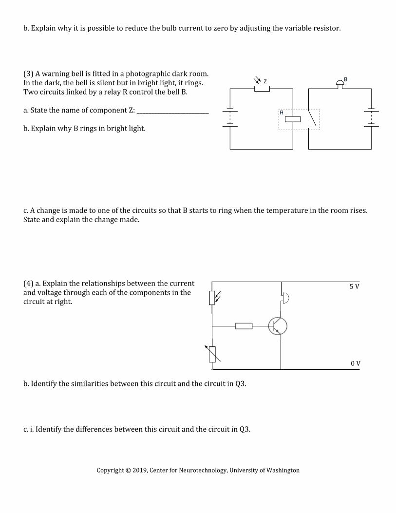
b. Explain why it is possible to reduce the bulb current to zero by adjusting the variable resistor. (3) A warning bell is fitted in a photographic dark room. In the dark, the bell is silent but in bright light, it rings. Two circuits linked by a relay R control the bell B. a. State the name of component Z: _________________________ b. Explain why B rings in bright light. c. A change is made to one of the circuits so that B starts to ring when the temperature in the room rises. State and explain the change made. (4) a. Explain the relationships between the current and voltage through each of the components in the circuit at right. b. Identify the similarities between this circuit and the circuit in Q3. c. i. Identify the differences between this circuit and the circuit in Q3.
5 V
0 V

Copyright © 2019, Center for Neurotechnology, University of Washington
ii. What is the advantage in the first circuit? iii. What is the advantage in the second circuit?

Copyright © 2019, Center for Neurotechnology, University of Washington
Unit: Circuitry and Sensory Substitution Devices Student Handout 2.4: Homework 1—Sensor Circuits Name:_____________________________________________ Date:______________________ Period:______ Directions: Answer the following questions in the space provided, working alone. (1) A student carries out an experiment with the circuit shown in the figure at right. The component in the dashed box labelled X is a diode. a. Draw the correct symbol for a diode, connected either way round, in the dashed box labelled X. b. +6.0V is applied to point A, 0V to point B. State and explain what the student observes on the ammeter. c. –6.0V is applied to point A, 0V to point B. State and explain what the student observes on the ammeter. d. The voltage shown is applied to the point A of the circuit. Point B is kept at 0V. On the graph below, draw a graph of the readings indicated by the voltmeter.

Copyright © 2019, Center for Neurotechnology, University of Washington
e. The circuit below contains two switches and two indicator lamps. Complete the table to state whether the lamps are on or off with the switches in the positions stated.
(2) a. Identify the components and their function in the time-delay circuit at right. b. State and explain the effect on the operation of the circuit of increasing the resistance in the variable resistor.

Copyright © 2019, Center for Neurotechnology, University of Washington
c. Design a circuit to activate an alarm circuit a short time after closing a switch. Include suitable components to switch the alarm circuit on via a transistor-operated relay. Draw the circuit diagram for your design. d. State and explain another use of a time-delay circuit.

Copyright © 2019, Center for Neurotechnology, University of Washington
Unit: Circuitry and Sensory Substitution Devices Student Handout 2.5: Truth Table Name:_____________________________________________ Date:______________________ Period:______
___Gate + Symbol _____Truth Table ____Description/Application__
In Out
In Out
In Out
In Out
In Out

Copyright © 2019, Center for Neurotechnology, University of Washington
Unit: Circuitry and Sensory Substitution Devices Student Handout 2.6: Practice 2—Logic Circuits Name:_____________________________________________ Date:______________________ Period:______ (1) One way to think of logic gate types is to consider what input states guarantee a certain output state. For example, we could describe the function of an AND gate as such: Any low input guarantees a low output. Identify what type of gate is represented by each of the following phrases: a. Any high input guarantees a low output. _____________________________________
b. Any low input guarantees a high output. _____________________________________
c. Any low input guarantees a low output. ______________________________________
(2) Crude logic gates circuits may be constructed out of nothing but diodes and resistors. Identify what type of logic function is represented by this gate circuits, and explain.
Directions: In the following situations, a combination of sensors and logic gates must be used in order to achieve the desired outcome. Sketch the appropriate circuit. (3) In hospitals, babies sometimes need to be kept warm in incubators for a period of time after birth. Design a system that will sound an alarm if the incubator gets too cold. (4) Some hospital rooms get very warm in the summer. We need an automatic fan to cool the patients. The fan should also be able to be turned on manually. Design this fan control system. (5) A photographer needs to use a remote camera shutter release that will be activated when the birds land on a feeding table. Design a circuit that ensures that the camera only works during daylight hours.

Copyright © 2019, Center for Neurotechnology, University of Washington
(6) Design a system that will turn on the A/C system when the temperature rises above a thermostat setting. A manual control switch should also be included for continuous operation of the system. (7) The figure at right shows a circuit that switches on a warning lamp when the temperature in an oven falls below a set value. a. Explain, with reference to the components in the circuit and point P, why the warning lamp is on when the temperature in the oven is below the set value. b. Explain effect of changing the resistance of R. (8) The figure below shows an electronic circuit controlling an electric heater. a. State what happens to P when its temperature falls. b. For the relay to operate, the output of the gate must be high (logic 1). What must be the input of the gate for the relay to operate? Explain your response. c. State what the resistance of P must be, compared with that of Q, in order to give this input: ______________

Copyright © 2019, Center for Neurotechnology, University of Washington
d. Under what conditions will P have this resistance? e. Suggest why component Q is a variable resistor, rather than one with a fixed value. f. Suggest a practical use for this circuit.

Copyright © 2019, Center for Neurotechnology, University of Washington
Unit: Circuitry and Sensory Substitution Devices Student Handout 2.7: Homework 2—Logic Circuits Name:_____________________________________________ Date:______________________ Period:______ Directions: Answer the following questions on your own, in the space provided. For Q 1, complete the truth table for each logic gate combination. (1) (2) Design a “babysitting” circuit that warns parents with a bell when their child turns on a lamp or when the temperature falls below a certain limit. Explain briefly and include a truth table. (3) The two inputs of the NAND gate are joined together and connected to an input C. a. Determine the output of this NAND gate when input C is set to 0 and when it is set to 1. b. State the logic gate that behaves in the same way as the NAND gate above: ______________________________ c. A circuit combines three NAND gates. The inputs to the circuit are P and Q, as shown. Points R, S and T in the circuit are labeled. Input P is set to 0 and input Q is set to 1.Determine the logic states of points R, S and T. R = _______________ S = _______________ T = ___________ (4) Answer question 2 on page 199 in your book (you’ll probably need to go onto the back).
Inputs A B
Output
0 0 1 0 0 1 1 1
Inputs A B
Output
0 0 1 0 0 1 1 1

Copyright © 2019, Center for Neurotechnology, University of Washington
Unit: Circuitry and Sensory Substitution Devices Student Handout 2.8: Formative Assessment—Complex Circuitry (IGCSE Physics) Name:_____________________________________________ Date:______________________ Period:______ Directions: Answer the following questions in the space provided. Explain your thinking clearly. (1) The fuel for an engine needs to be warm in order for the engine to work. If the temperature of the fuel is below the working temperature TW, an LED emits light. a. Label each of the four elements in the circuit, and identify their purpose. i. _____________________________________________ ii. _____________________________________________ iii. _____________________________________________ iv. _____________________________________________ b. Describe the relationships between the current and voltage through each of the four elements. Explain. (2) Currently the fuel is too cold and the LED is emitting light. State and explain what happens in the above circuit as the temperature of the fuel increases to a value above TW.

Copyright © 2019, Center for Neurotechnology, University of Washington
(3) The circuit is modified as shown. Predict and explain what happens in this circuit, and suggest a practical use.

Copyright © 2019, Center for Neurotechnology, University of Washington
Unit: Circuitry and Sensory Substitution Devices Student Handout 2.9: Self-assessment—Complex Circuitry (IGCSE Physics) Name:_____________________________________________ Date:______________________ Period:______ Brain Check: Below are our unit learning goals. Based on your work so far, how confident are you feeling about each? Rank from 1 to 5 (1 = most confident).
You should be able to… BFA AFA BSA
Draw and interpret circuit diagrams containing sources, switches, resistors (fixed and variable), heaters, thermistors, light-dependent resistors, lamps, ammeters, voltmeters, galvanometers, magnetizing coils, transformers, bells, fuses, relays, and diodes
Describe the action of a variable potential divider (potentiometer)
Describe the action of thermistors and light dependent resistors and show understanding of their use as input transducers
Describe the action of a relay and show understanding of its use in switching circuits.
Describe the action of a diode and show understanding of its use as a rectifier
Show understanding of circuits operating as light sensitive switches and temperature-operated alarms (to include a relay)
Directions: Review your answers to the formative assessment and shade in the answers/reasoning that you included. Then comment on your misconceptions and what you don’t yet understand, as well has how you are going to improve before the next assessment.
Question Answer Description/Reasoning
1a Batt, var. resistor, thermistor, LED provide power control current Hotter = less resistance Light up
1b I: Batt = X = Y + LED V: Batt = X + Y/LED
X alone gets all current, Y and LED split unevenly Each loop adds to volt. of batt, so X + Y = X + LED = batt
Issues and improvements?
Question Answer Description/Reasoning
2 LED goes off R of thermistor decreases so I increases More current through thermistor than LED V across LED decreases
Issues and improvements?
Question Answer Description/Reasoning
3 LED lights as hotter Warning if overheat
If hot, low resist. in thermistor so high current in circuit More current/voltage through LED so lights
Issues and improvements?

Copyright © 2019, Center for Neurotechnology, University of Washington
Copyright © 2019, Center for Neurotechnology, University of Washington
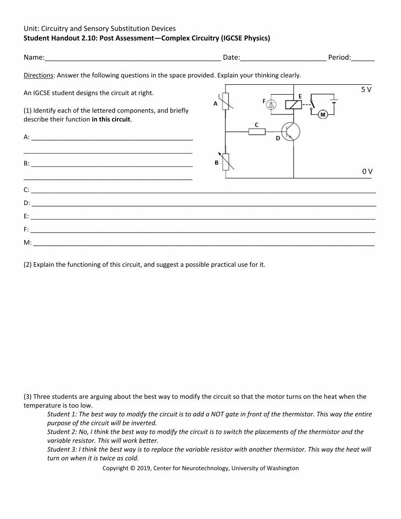
Unit: Circuitry and Sensory Substitution Devices Student Handout 2.10: Post Assessment—Complex Circuitry (IGCSE Physics) Name:_____________________________________________ Date:______________________ Period:______ Directions: Answer the following questions in the space provided. Explain your thinking clearly. An IGCSE student designs the circuit at right. (1) Identify each of the lettered components, and briefly describe their function in this circuit. A: _____________________________________________
_______________________________________________
B: _____________________________________________
_______________________________________________
C: ________________________________________________________________________________________________
D: ________________________________________________________________________________________________
E: ________________________________________________________________________________________________
F: ________________________________________________________________________________________________
M: _______________________________________________________________________________________________
(2) Explain the functioning of this circuit, and suggest a possible practical use for it. (3) Three students are arguing about the best way to modify the circuit so that the motor turns on the heat when the temperature is too low.
Student 1: The best way to modify the circuit is to add a NOT gate in front of the thermistor. This way the entire purpose of the circuit will be inverted. Student 2: No, I think the best way to modify the circuit is to switch the placements of the thermistor and the variable resistor. This will work better. Student 3: I think the best way is to replace the variable resistor with another thermistor. This way the heat will turn on when it is twice as cold.

Copyright © 2019, Center for Neurotechnology, University of Washington
Which student, if either, do you agree with? Explain your reasoning.