led light installation - big ass solutions · led light installation ... the requirements specified...
TRANSCRIPT
1877-BIG-FANS © 2015 DELTA T CORP. ALL RIGHTS RESERVED REV. D PX2-INST-48-MUL-01
LED LIGHT INSTALLATIONThe following instructions are for installing the LED light module on Powerfoil X2.0 and Powerfoil X3.0 fans with a static tube. Consult the complete Installation Guide for all other aspects of fan installation and safety guidelines.
WARNING: Disconnect the fan from the power supply before installing the LED light.
CAUTION: To reduce the risk of fire and electric shock, this light kit should be used only with Powerfoil X2.0 and Powerfoil X3.0 fans.
WARNING: Installation work and electrical wiring must be done by qualified person(s) in accordance with the requirements specified in these instructions and with all national and local electrical codes.
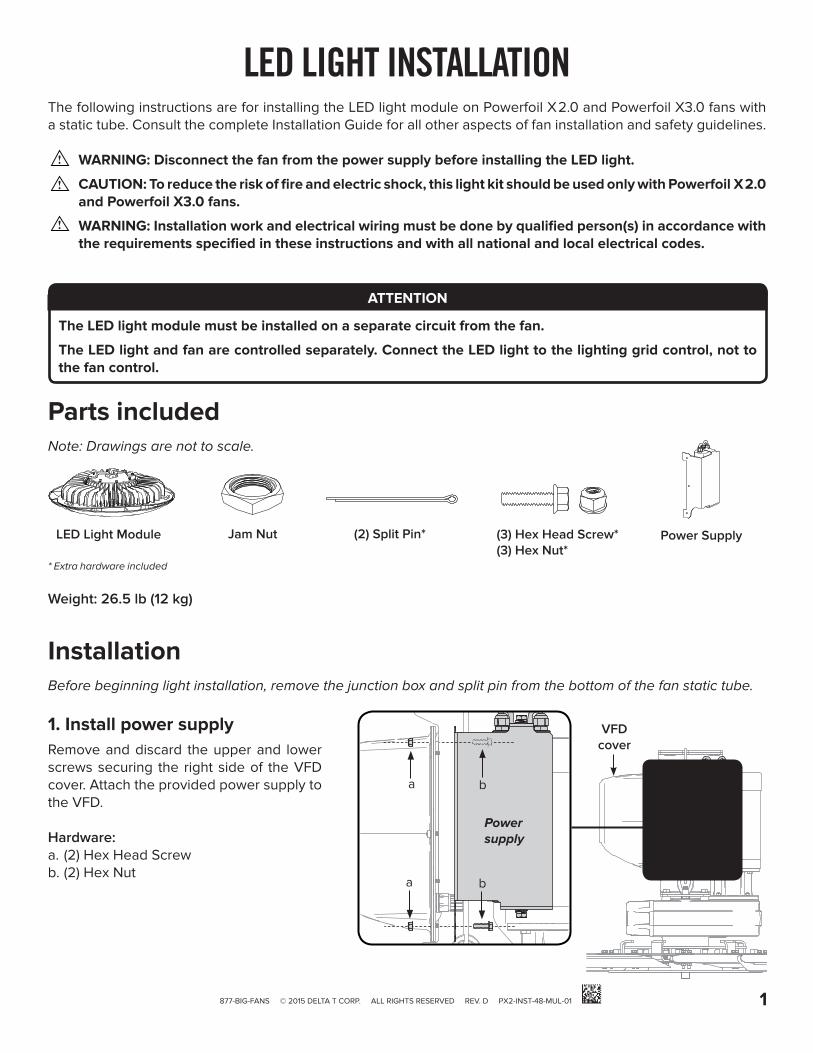
InstallationBefore beginning light installation, remove the junction box and split pin from the bottom of the fan static tube.
1. Install power supplyRemove and discard the upper and lower screws securing the right side of the VFD cover. Attach the provided power supply to the VFD.
Hardware:a. (2) Hex Head Screwb. (2) Hex Nut
a
a
b
b
VFD cover
Power supply
Parts includedNote: Drawings are not to scale.
LED Light Module Power SupplyJam Nut (3) Hex Head Screw*(3) Hex Nut*
Weight: 26.5 lb (12 kg)
* Extra hardware included
ATTENTION
The LED light module must be installed on a separate circuit from the fan.
The LED light and fan are controlled separately. Connect the LED light to the lighting grid control, not to the fan control.
(2) Split Pin*

2 877-BIG-FANS © 2015 DELTA T CORP. ALL RIGHTS RESERVED REV. D PX2-INST-48-MUL-01
2. Route power supply wiring and install jam nutRoute the DC wires from the power supply through the static tube. Depending on the wattage, the power supply will have one cable with two wires or two cables with two wires.
Thread the provided jam nut onto the static tube. Hand tighten until the jam nut is as tight and as far up the static tube as possible.
Jam nut DC wires (1 or 2 cables)
Static tube
Light module (2 or 4 wires)
3. Connect LED light module wiringRaise the LED light module to the static tube. Connect the power supply wires to the light module wires of the same color, and then tuck the wires and connectors inside the module. Tuck ONLY the light module wires and connectors inside the module. Do not tuck the power supply wires or cables into the module.
Depending on the wattage, the power supply will have either one cable with two wires or two cables with two wires. The light module will have either two wires or four wires.
DC wires (1 or 2 cables)
Jam nut
Do not connect individual power supply wires to different pairs of light module wires.

3877-BIG-FANS © 2015 DELTA T CORP. ALL RIGHTS RESERVED REV. D PX2-INST-48-MUL-01
4. Connect power supply wiringRefer to the input voltage rating marked on the LED light module, and then wire according to the diagram and table.
Supply voltageLED module’s L1 (black) connects to
LED module’s L2 (white) connects to
Low
vol
tage
(1
20
–277
V ±
15
%)
120 VAC, 1 Ф derived from 1 Ф, 240/120 V panel
H (black) N (white)
208 VAC, 3 Ф derived from 3 Ф, 208/120 V panel
L1 (black), L2 (red), or L3 (blue)
L2 (red), L3 (blue), or L1 (black)
240 VAC, 1 Ф derived from 1 Ф, 240/120 V panel
L1 (black) L2 (red)
240 VAC, 1 Ф derived from 3 Ф, 240/120 V panel, B phase wild
L1 (black), L2 (orange), or L3 (blue)
L2 (orange), L3 (blue), or L1 (black)
All 277 VAC, 1 Ф derived from
3 Ф, 480/277 V panelL1 (brown), L2 (orange), or L3 (yellow)
N (white)
Hig
h vo
ltage
(3
47–4
80
V ±
15
%) 347 VAC, 1 Ф derived from
3 Ф, 600/347 V panelL1 (red), L2 (black), or L3 (blue)
N (white)
480 VAC, 3 Ф derived from 3 Ф, 480/277 V panel
L1 (brown), L2 (orange), or L3 (yellow)
L2 (orange), L3 (yellow), or L1 (brown)
480 VAC, 1 Ф derived from 3 Ф, 480 V panel, corner ground
L1 (brown) or L3 (yellow)L2/Grounded conductor (white or gray)
GROUND (GREEN IN US/CA; GREEN W/ YELLOW OUTSIDE US/CA )
L1 (BLACK IN US/CA; BROWN OUTSIDE US/CA)
L2 (WHITE IN US/CA; BLUE OUTSIDE US/CA)
DIM- (BLACK)
DIM+ (RED)
POWER SUPPLY
GROUND
L1
L2
SUPPLY POWER
DIM- (GREY)
DIM+ (VIOLET)
DIMMING (1–10 V DC)

4 877-BIG-FANS © 2015 DELTA T CORP. ALL RIGHTS RESERVED REV. D PX2-INST-48-MUL-01
5. Attach LED module to static tubeWhile raising the LED module to the static tube, carefully pull the power supply cable(s) and wires up into the static tube from the top. The wiring should be pulled far enough into the tube so that the cable(s) are clear of the small holes at the bottom of the tube and will not interfere with split pin installation.
Align the threading on top of the LED module with the threading on the end of the static tube. Carefully screw the light module onto the static tube by turning clockwise until the holes in the static tube and the top of the light module align so the split pin can be inserted.
View from below
6. Install split pin and tighten jam nutBe careful not to damage the wires inside the static tube when inserting the split pin.
Using needle-nose pliers, insert the split pin through the holes in the light module and static tube. Bend back the ends of the split pin to lock it in place. Tighten the jam nut against the light module with a wrench.
Split pinJam nut
The fan is hidden in the illustration so that the static tube and the top of the light module are visible.

877-BIG-FANS © 2015 DELTA T CORP. TOUS DROITS RÉSERVÉS RÉV. D PX2-INST-48-MUL-01 5
INSTALLATION DU MODULE D’ÉCLAIRAGE À DELCette notice concerne l’installation du module d’éclairage à DEL sur les ventilateurs Powerfoil X2.0 et Powerfoil X3.0 à tige fixe. Veuillez consulter le manuel d’installation du ventilateur pour obtenir des informations détaillées sur son installation et connaître les consignes de sécurité à respecter.
AVERTISSEMENT : Coupez l’alimentation du ventilateur avant d’installer le module d’éclairage à DEL.
ATTENTION : Pour limiter les risques d’incendie et d’électrocution, ce module d’éclairage doit uniquement être utilisé avec les ventilateurs Powerfoil X2.0 et Powerfoil X3.0.
AVERTISSEMENT : L’installation et le câblage doivent être effectués par une ou plusieurs personnes qualifiées, conformément aux exigences décrites dans la présente notice et dans le respect de toutes les normes de sécurité électrique en vigueur aux niveaux local et national.
Composants fournisRemarque : les dessins ne sont pas à l’échelle.
Module d’éclairage à DEL Bloc d’alimentation
Contre-écrou Vis à tête hexagonale* (3)Écrou hexagonal* (3)
Poids : 12 kg (26,5 lb)
* Visserie et accessoires supplémentaires fournis
ATTENTION
Le module d’éclairage à DEL doit être branché sur un circuit séparé de celui du ventilateur.
L’éclairage à DEL et le ventilateur sont commandés séparément. L’éclairage à DEL doit être relié au dispositif de commande du circuit d’éclairage, et non au dispositif de commande du ventilateur.
a
a
b
b
Cache du VFD
Bloc d’alimentation
Goupille fendue* (2)
InstallationAvant de procéder à l’installation du module d’éclairage à DEL, démontez la boîte de dérivation et retirez la goupille fendue en bas de la tige fixe du ventilateur.
1. Mise en place de bloc d’alimentationRetirez les vis supérieure et inférieure maintenant le côté droit du cache du VFD et jetez-les. Fixez bloc d’alimentation fournie au VFD.
Visserie :a. Vis à tête hexagonale (2)b. Écrou hexagonal (2)

877-BIG-FANS © 2015 DELTA T CORP. TOUS DROITS RÉSERVÉS RÉV. D PX2-INST-48-MUL-01 6
2. Passage des fils d’alimentation et mise en place du contre-écrouFaites passer les fils CC de l’alimentation dans la tige fixe. Selon la puissance électrique, l’alimentation comporte un câble de deux fils ou deux câbles de deux fils.
Vissez le contre-écrou fourni sur la tige fixe. Serrez-le à la main le plus fermement et le plus haut possible sur la tige fixe.
Contre-écrou Fils CC (1 ou 2 câbles)
Tige fixe
Module DEL (2 ou 4 fils)
3. Connexion des fils du le module d’éclairage à DELAmenez le module DEL au niveau de la tige fixe. Connectez les fils de l’alimentation aux fils de même couleur du module, puis rangez les fils du module ainsi que leurs connecteurs à l’intérieur du module. Rangez UNIQUEMENT les fils du module DEL et leurs connecteurs à l’intérieur du module. Ni les fils ni les câbles de l’alimentation ne doivent être rangés dans le module.
Selon la puissance électrique, bloc d’alimentation comporte soit un câble de deux fils, soit deux câbles de deux fils. Le module DEL comporte soit deux fils munis de connecteurs, soit quatre fils munis de connecteurs.
Fils CC (1 ou 2 câbles)
Contre-écrou
Ne permutez pas les paires de fils de l’alimentation et du module DEL.

877-BIG-FANS © 2015 DELTA T CORP. TOUS DROITS RÉSERVÉS RÉV. D PX2-INST-48-MUL-01 7
4. Connexion des fils de d’alimentationVérifiez la tension assignée indiquée sur le module d’éclairage à DEL, puis procédez au câblage conformément au schéma et au tableau suivants.
Tension d’alimentationFil de phase L1 (noir) du module DEL connecté à
Fil de phase L2 (blanc) du module DEL connecté à
Bas
se te
nsio
n
(12
0–2
77 V
± 1
5 %
)
120 V CA, 1 Ф issue d’un tableau 1 Ф, 240/120 V
H (noir) N (blanc)
208 V CA, 3 Ф issue d’un tableau 3 Ф, 208/120 V
L1 (noir), L2 (rouge) ou L3 (bleu)
L2 (rouge), L3 (bleu) ou L1 (noir)
240 V CA, 1 Ф issue d’un tableau 1 Ф, 240/120 V
L1 (noir) L2 (rouge)
240 V CA, 1 Ф issue d’un tableau 3 Ф, 240/120 V, avec phase B sauvage
L1 (noir), L2 (orange) ou L3 (bleu)L2 (orange), L3 (bleu) ou L1 (noir)
Tous 277 V CA, 1 Ф issue d’un
tableau 3 Ф, 480/277 VL1 (marron), L2 (orange) ou L3 ( jaune)
N (blanc)
Hau
te te
nsio
n
(347
–48
0 V
± 1
5 %
) 347 V CA, 1 Ф issue d’un tableau 3 Ф, 600/347 V
L1 (rouge), L2 (noir) ou L3 (bleu) N (blanc)
480 V CA, 3 Ф issue d’un tableau 3 Ф, 480/277 V
L1 (marron), L2 (orange) ou L3 ( jaune)
L2 (orange), L3 ( jaune) ou L1 (marron)
480 V CA, 1 Ф issue d’un tableau 3 Ф, 480 V, avec phase reliée à la terre
L1 (marron) ou L3 ( jaune)L2/conducteur relié à la terre (blanc ou gris)
TERRE (VERT AUX ÉTATS-UNIS ET AU CANADA ; VERT ET JAUNE DANS LES AUTRES PAYS)
L1 (NOIR AUX ÉTATS-UNIS ET AU CANADA ; MARRON DANS LES AUTRES PAYS)
L2 (BLANC AUX ÉTATS-UNIS ET AU CANADA ; BLEU DANS LES AUTRES PAYS)
DIM- (NOIR)
DIM+ (ROUGE)
BLOC D’ALIMENTATION
TERRE
L1
L2
TENSION D’ALIMENTATION
DIM- (GRIS)
DIM+ (VIOLET)
GRADATION (1–10 V CC)

877-BIG-FANS © 2015 DELTA T CORP. TOUS DROITS RÉSERVÉS RÉV. D PX2-INST-48-MUL-01 8
5. Fixation du module DEL à la tige fixeTout en soulevant le module DEL pour l’amener au niveau de la tige fixe, tirez doucement sur le(s) câble(s) et les fils de l’alimentation, par le haut, pour les faire remonter dans la tige fixe. Ces derniers doivent être remontés suffisamment haut dans la tige pour ne pas obstruer les petits trous situés en bas de la tige et ne pas entraver le passage de la goupille fendue.
Alignez le filetage de la partie supérieure du module DEL sur celui de l’extrémité de la tige fixe. Vissez doucement le module DEL sur la tige fixe, en travaillant dans le sens des aiguilles d’une montre, jusqu’à ce que les trous ménagés dans la tige fixe et dans la partie supérieure du module DEL soient alignés, permettant ainsi l’insertion de la goupille fendue.
Vue du dessous
6. Mise en place de la goupille fendue et serrage du contre-écrouAttention à ne pas endommager les fils situés à l’intérieur de la tige fixe lors de l’insertion de la goupille fendue.
À l’aide d’une pince à bec long, insérez la goupille fendue dans les trous du module d’éclairage et de la tige fixe. Rabattez les bras de la goupille fendue pour l’immobiliser. À l’aide d’une clé, serrez le contre-écrou contre le module DEL.
Goupille fendueContre-écrou
Pour que la tige fixe et la partie supérieure du module DEL soient visibles, le ventilateur n’a pas été représenté sur cette illustration.