lecture+03 (1)
TRANSCRIPT

8/12/2019 Lecture+03 (1)
http://slidepdf.com/reader/full/lecture03-1 1/36
440:221 Intro to Engineering Mechanics: Statics
1
Lecture 3Vector operations
Spring 2014Based on Textbook Material: Engineering Mechanics Statics, 12th Edition, R.C. Hibbeler, Pearson 2010.
Alberto Cuitino, Heather Emady,
Sara Salahi, Bereket YohannesInstructors
Juan Ren, Jingjin Xie
Assistants

8/12/2019 Lecture+03 (1)
http://slidepdf.com/reader/full/lecture03-1 2/36
440:221 Lectures
School of Engineering, Spring 2014
Topics to be reviewed
• What is a Cartesian vector representation?
• What is a Cartesian component?• How do we add vectors using Cartesian components?
• What is a unit vector? What is a vector position?
• How do find a force along a given direction?
• What is the inner (or dot) product?
• What is the inner product useful for?
2

8/12/2019 Lecture+03 (1)
http://slidepdf.com/reader/full/lecture03-1 3/36
440:221 Lectures
School of Engineering, Spring 2014
Scalar Notation – 2D
3
F Rx = F cos
F Ry = F sin

8/12/2019 Lecture+03 (1)
http://slidepdf.com/reader/full/lecture03-1 4/36
440:221 Lectures
School of Engineering, Spring 2014
Cartesian Vector Notation – 2D
4
• Resolve vectors into components
using the x and y axis system.
• Each component of the vector is
shown as a magnitude and a
direction.
• The directions are based on the xand y axes.
• We use the “unit vectors” i and j to
designate the x and y axes.
F = F x i + F y j

8/12/2019 Lecture+03 (1)
http://slidepdf.com/reader/full/lecture03-1 5/36
440:221 Lectures
School of Engineering, Spring 2014
• Step 1 is to resolve eachforce into its components.
Adding Vectors using Cartesian Components
5
• Step 3 is to find the magnitude
and angle of the resultant
vector.
• Step 2 is to add all the x-
components together, followed byadding all the y components
together. These two totals are
the x and y components of the
resultant vector.

8/12/2019 Lecture+03 (1)
http://slidepdf.com/reader/full/lecture03-1 6/36
440:221 Lectures
School of Engineering, Spring 2014
Adding Vectors using Cartesian Components
6
Break the three vectors into components, then add them.
FR = F1 + F2 + F3
= F1x i + F1y j F2x i + F2y j + F3x i F3y j
= (F1x F2x + F3x) i + (F1y + F2y F3y) j
= (FRx
) i + (FRy
) j

8/12/2019 Lecture+03 (1)
http://slidepdf.com/reader/full/lecture03-1 7/36
440:221 Lectures
School of Engineering, Spring 2014
Examples
7

8/12/2019 Lecture+03 (1)
http://slidepdf.com/reader/full/lecture03-1 8/36
440:221 Lectures
School of Engineering, Spring 2014
Examples
8
8/12/2019 Lecture+03 (1)
http://slidepdf.com/reader/full/lecture03-1 9/36
440:221 Lectures
School of Engineering, Spring 2014
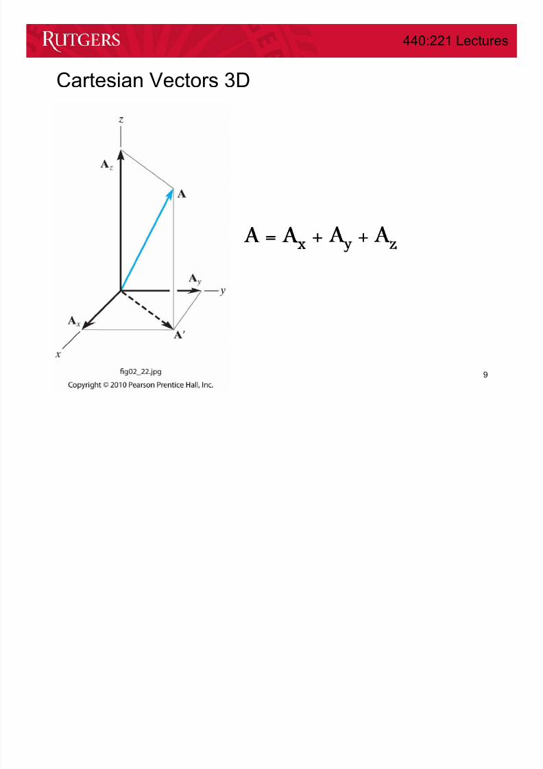
Cartesian Vectors 3D
9
A = Ax Ay Az

8/12/2019 Lecture+03 (1)
http://slidepdf.com/reader/full/lecture03-1 10/36
440:221 Lectures
School of Engineering, Spring 2014
Characteristics of a unit vector :
a) Its magnitude is 1.
b) It is dimensionless (has no units).
c) It points in the same direction as the original
vector ( A).
For a vector A, with a magnitude of A, an
unit vector is defined as
u A = A / A .
The unit vectors in the Cartesian axis systemare i, j, and k. They are unit vectors along the
positive x, y, and z axes respectively.
Cartesian unit vectors

8/12/2019 Lecture+03 (1)
http://slidepdf.com/reader/full/lecture03-1 11/36
440:221 Lectures
School of Engineering, Spring 2014
Consider a box with sides AX, AY, and AZ meters
long.
The vector A can be defined as
A = ( AX i + AY j + AZ k)
The projection of vector A in the x-y plane is A´. The magnitude of A´ is
found by using the same approach as a 2-D vector: A´ = (AX2 + AY
2)1/2 .
The magnitude of the position vector A can now be obtained as
A = ((A´)2 + AZ2) ½ = (AX
2 + AY2 + AZ
2) ½
Cartesian vector representation

8/12/2019 Lecture+03 (1)
http://slidepdf.com/reader/full/lecture03-1 12/36
440:221 Lectures
School of Engineering, Spring 2014
These angles are
measured betweenthe vector and the
positive X, Y and Z
axes, respectively.Their range of values
are from 0° to 180°
The direction or orientation of
vector A is defined by theangles , β, and γ.
Direction of a Cartesian vector

8/12/2019 Lecture+03 (1)
http://slidepdf.com/reader/full/lecture03-1 13/36
440:221 Lectures
School of Engineering, Spring 2014
Using trigonometry, “direction cosines” are found using
These angles are not independent.
They must satisfy the following equation:
cos ² + cos ² + cos ² = 1
Direction of a Cartesian vector

8/12/2019 Lecture+03 (1)
http://slidepdf.com/reader/full/lecture03-1 14/36
440:221 Lectures
School of Engineering, Spring 2014
This result can be derived from the
definition of a coordinate direction angles
and the unit vector. Recall, the formula
for finding the unit vector of any position
vector:
Direction of a Cartesian vector
or written another way,
u A = cos i + cos j + cos k

8/12/2019 Lecture+03 (1)
http://slidepdf.com/reader/full/lecture03-1 15/36
440:221 Lectures
School of Engineering, Spring 2014
For example, if
A = AX i + AY j + AZ k and
B = BX i + BY j + BZ k , then
A + B = (AX + BX) i + (AY + BY) j + (AZ + BZ) k
or
A – B = (AX - BX) i + (AY - BY) j + (AZ - BZ) k .
Once individual vectors are written in Cartesian form, it is
easy to add or subtract them. The process is essentially
the same as when 2-D vectors are added.
Addition of cartesian vectors

8/12/2019 Lecture+03 (1)
http://slidepdf.com/reader/full/lecture03-1 16/36
440:221 Lectures
School of Engineering, Spring 2014
Examples
16

8/12/2019 Lecture+03 (1)
http://slidepdf.com/reader/full/lecture03-1 17/36
440:221 Lectures
School of Engineering, Spring 2014
Examples
17

8/12/2019 Lecture+03 (1)
http://slidepdf.com/reader/full/lecture03-1 18/36
440:221 Lectures
School of Engineering, Spring 2014
Vector Position
18

8/12/2019 Lecture+03 (1)
http://slidepdf.com/reader/full/lecture03-1 19/36
440:221 Lectures
School of Engineering, Spring 2014
Vector Position
19
A position vector is defined as a fixed vector that locates a
point in space relative to another point.
8/12/2019 Lecture+03 (1)
http://slidepdf.com/reader/full/lecture03-1 20/36
440:221 Lectures
School of Engineering, Spring 2014
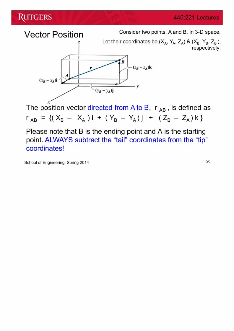
Vector Position
20
The position vector directed from A to B, r AB , is defined as
r AB = {( XB – X A ) i + ( YB – Y A ) j + ( ZB – Z A ) k }
Please note that B is the ending point and A is the starting
point. ALWAYS subtract the “tail” coordinates from the “tip”
coordinates!
Consider two points, A and B, in 3-D space.
Let their coordinates be (X A, Y A, Z A) & (XB, YB, ZB ),
respectively.

8/12/2019 Lecture+03 (1)
http://slidepdf.com/reader/full/lecture03-1 21/36
440:221 Lectures
School of Engineering, Spring 2014
Example
21
Direction from A to B
Distance

8/12/2019 Lecture+03 (1)
http://slidepdf.com/reader/full/lecture03-1 22/36
440:221 Lectures
School of Engineering, Spring 2014
Example
22

8/12/2019 Lecture+03 (1)
http://slidepdf.com/reader/full/lecture03-1 23/36
440:221 Lectures
School of Engineering, Spring 2014
Example
23

8/12/2019 Lecture+03 (1)
http://slidepdf.com/reader/full/lecture03-1 24/36
440:221 Lectures
School of Engineering, Spring 2014
Force Vector Directed Along a Line
24

8/12/2019 Lecture+03 (1)
http://slidepdf.com/reader/full/lecture03-1 25/36
440:221 Lectures
School of Engineering, Spring 2014
Force Vector Directed Along a Line
25
If a force is directed along a line, then we can represent the force vector
in Cartesian coordinates by using a unit vector and the force’s
magnitude. So we need to:

8/12/2019 Lecture+03 (1)
http://slidepdf.com/reader/full/lecture03-1 26/36
440:221 Lectures
School of Engineering, Spring 2014
Force Vector Directed Along a Line
26
Procedure
1) Find the position vector, r AB ,
along two points on that line.
2) Find the unit vector describing
the line’s direction, u AB =
(r AB/r AB).
3) Multiply the unit vector by the
magnitude of the force, F = F
u AB .

8/12/2019 Lecture+03 (1)
http://slidepdf.com/reader/full/lecture03-1 27/36
440:221 Lectures
School of Engineering, Spring 2014
Example
27
Find Force at A

8/12/2019 Lecture+03 (1)
http://slidepdf.com/reader/full/lecture03-1 28/36
440:221 Lectures
School of Engineering, Spring 2014
Example
28

8/12/2019 Lecture+03 (1)
http://slidepdf.com/reader/full/lecture03-1 29/36
440:221 Lectures
School of Engineering, Spring 2014
Example
29

8/12/2019 Lecture+03 (1)
http://slidepdf.com/reader/full/lecture03-1 30/36
440:221 Lectures
School of Engineering, Spring 2014
Dot Product
30
A
B
A ▪ B = A B cos
A▪
B = B▪
A Commutativea ( A ▪ B) = (a A) ▪ B = A ▪ (a B) Multipl ication by a scalar
A ▪ (B + D) = ( A ▪ B) + ( A ▪ D) Distributive Law

8/12/2019 Lecture+03 (1)
http://slidepdf.com/reader/full/lecture03-1 31/36
440:221 Lectures
School of Engineering, Spring 2014
Dot Product
31
A
B
A ▪ B = Ax Bx + Ay By + Az Bz

8/12/2019 Lecture+03 (1)
http://slidepdf.com/reader/full/lecture03-1 32/36
440:221 Lectures
School of Engineering, Spring 2014
Dot Product Applications
32
A
B = cos-1 ( A ▪ B / A B)
1) Angle between two directions
2) Components parallel and perpendicular to a line

8/12/2019 Lecture+03 (1)
http://slidepdf.com/reader/full/lecture03-1 33/36
440:221 Lectures
School of Engineering, Spring 2014
Example
33
Find Projections parallel
and perpendicular to AB

8/12/2019 Lecture+03 (1)
http://slidepdf.com/reader/full/lecture03-1 34/36
440:221 Lectures
School of Engineering, Spring 2014
Example
34

8/12/2019 Lecture+03 (1)
http://slidepdf.com/reader/full/lecture03-1 35/36
440:221 Lectures
School of Engineering, Spring 2014
Example
35
440 221 L

8/12/2019 Lecture+03 (1)
http://slidepdf.com/reader/full/lecture03-1 36/36
440:221 Lectures
School of Engineering, Spring 2014
Take-home message
• Addition using Cartesian components is simple
– Add all components in each direction using scalar addition
– Similar procedure for 2 and 3 dimensional cases
– Quite practical for 3D problems
• The direction from A to B is easily determined by
– r AB = {( XB – X A ) i + ( YB – Y A ) j + ( ZB – Z A ) k }
• The inner (dot) product can be easily computed by
– A ▪ B = Ax Bx + Ay By + Az Bz
• The inner product is useful to find
– Angles between directions
– Projections of forces along directions
36