lecture - university of babylon · cotton rolls, cellulose wafers, and gauze sponges provide...
TRANSCRIPT

Lecture
Isolation of the
operating field

Isolation of the operating field
Problems during restorative treatment.
Figure 1. A, Radiograph of swallowed casting in patient‘s stomach.
B, Radiograph of casting lodged in patient's throat.
Introduction

The goals of operating field isolation are:
harm prevention (Excessive saliva and handpiece spray can alarm the patient. Small instruments and restorative debris can be aspirated or swallowed. Soft tissue can be damaged accidentally).
moisture control (sulcular fluid, saliva, and gingival bleeding from the operating field).
retraction (maintaining an open mouth and depressing or retracting the gingival tissue, tongue, lips, and cheek).
Isolation of the operating field

Figure 2. A, Behind the patient, the operator (or person who gave
injection), using only the syringe-holding hand, inserts the needle
partially into the sheath propped by prop/guard card, and then,
B, uprights syringe and sheath upon the tray or countertop and presses
the needle fully into sheath.
C, Operator lays resheathed syringe propped by card on countertop.
I-Local anesthesia
Isolation of the operating field
Techniques of isolation of the operating field

II-Rubber dam
Isolation of the operating field
Figure 3. Rubber dam kit.

Figure 4. Absorbents such as
cotton rolls, cellulose wafers,
and gauze sponges provide
satisfactory dryness for
short periods of time.
Figure 6. A cotton roll
holder in position.
Figure 5. Isolate maxillary
posterior teeth by placing
cotton roll in vestibule
adjacent to teeth.
III-Absorbents (cotton roll isolation and cellulose wafers).
Isolation of the operating field
Figure 7. Position
large cotton roll
between tongue and
teeth by "rolling" it
to place in direction
of arrow. B,
Properly positioned
facial and lingual
cotton rolls improve
access and visibility.

Figure 8. A throat screen is used during try-
in and removal of indirect restorations.
IV-Throat shields or throat screens (gauze sponges).
Isolation of the operating field

V-High-volume evacuators and saliva ejector
Isolation of the operating field
Figure 10. Saliva ejectors. Figure 9. Evacuator tip.

Figure 11. Retraction
cord placed in gingival
crevice. A, Cord
placement initiated. B,
A thin, flatbladed
instrument is used for
cord placement. C,
Cord placed.
Other isolation techniques: I-Retraction cord
II-Mirror and evacuator tip III-Mouth prop
IV-Drugs
Isolation of the operating field
Figure 12. Position of
evacuator tip for
maximal removal of
water and debris in
operating area. A,
With rubber dam
applied. B, With
cotton roll isolation.
Figure 13.
Chairside
assistant uses
air syringe to
dry teeth and
to keep
mirror free of
debris.

Other isolation techniques: I-Retraction cord
II-Mirror and evacuator tip III-Mouth prop
IV-Drugs
Isolation of the operating field
Figure 14. Mouth props. A, Block-type prop maintaining
mouth opening. B, Block-type prop. C, Ratchet-type prop.

Local anesthesia is important in moisture control.
It reduces salivation, apparently because the patient is more comfortable, less anxious, and less sensitive to oral stimuli, thus reducing salivary flow.
Local anesthetics incorporating a vasoconstrictor also reduce blood flow, thus helping to control hemorrhage at the operating site.
I-Local anesthesia
Isolation of the operating field

In 1864, S.C. Barnum, a New York City dentist, introduced the rubber dam into dentistry.
The rubber dam is used to define the operating field by isolating one or more teeth from the oral environment.
The dam eliminates saliva from the operating site and retracts the soft tissue.
The dam ensures appropriate dryness of the teeth and improves the quality of clinical restorative dentistry.
Isolation of the operating field II-Rubber dam

In general, the rubber dam is the most successful method of isolating the operating field.
a dry, clean operating field.
improved access and visibility.
potentially improved properties of dental materials.
operating efficiency.
protection of the patient and operator. In addition, most of the patients are more relaxed, because water spray and debris from the procedure are isolated from them..
Isolation of the operating field Advantages of rubber dam

Most frequently, time consumption and patient objection. They are reduced with the use of a simplified technique for application and removal.
Usually, the rubber dam can be placed in 3-5 minutes, it is the approximate time necessary for onset of anesthesia.
Isolation of the operating field Disadvantages of rubber dam

Certain oral conditions may preclude the use of the rubber dam:
teeth that have not erupted sufficiently to support a retainer.
some third molars.
extremely malpositioned teeth.
In addition, patients suffering from asthma may not tolerate the rubber dam if breathing through the nose is difficult.
In rare instances when the patient cannot tolerate a rubber dam because of psychologic reasons or latex allergy.
Isolation of the operating field Disadvantages of rubber dam
Isolation of the operating field
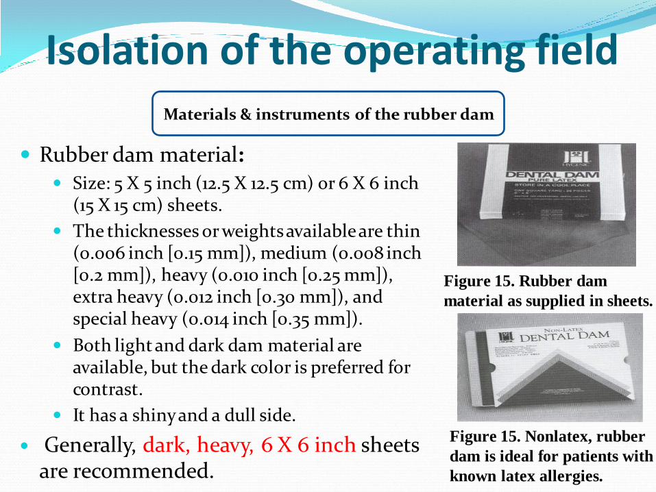
Figure 15. Rubber dam
material as supplied in sheets.
Rubber dam material:
Size: 5 X 5 inch (12.5 X 12.5 cm) or 6 X 6 inch (15 X 15 cm) sheets.
The thicknesses or weights available are thin (0.006 inch [0.15 mm]), medium (0.008 inch [0.2 mm]), heavy (0.010 inch [0.25 mm]), extra heavy (0.012 inch [0.30 mm]), and special heavy (0.014 inch [0.35 mm]).
Both light and dark dam material are available, but the dark color is preferred for contrast.
It has a shiny and a dull side.
Generally, dark, heavy, 6 X 6 inch sheets are recommended.
Materials & instruments of the rubber dam
Figure 15. Nonlatex, rubber
dam is ideal for patients with
known latex allergies.

Figure 16. The Young rubber
dam frame (holder).
Isolation of the operating field
Holder (frame) maintains the borders of the rubber dam in position. The Young holder is a U-shaped metal frame with small metal projections for securing the borders of the rubber dam. It is easily applied and comfortable for the patient.
Materials & instruments of the rubber dam

Figure 16 A. Foldable plastic rubber dam
frame (Plast-Frame) with hinge to allow
for easy film-sensor placement.
Figure 16 B. Plastic radiolucent and metal
rubber dam frames. Top left
Young's frame. Top center, Nygaard-Ostby
(N-O) frame.

Figure 16 C. The
Handidam is a rubber dam
system with built-in plastic
frame. The disposable
frame bends easily for film
placement.
Figure 16 D. The Quickdam is a
disposable isolation system with a
pliable outer ring.

Isolation of the operating field Materials & instruments of the rubber dam
Figure 17. Rubber dam
retainer. Note four-point prong
contact (arrows) with tooth.
Retainer (clamp), to anchor the dam to the most posterior tooth to be isolated. It is also used to retract gingival tissue.
Note: Experience will reduce the number of retainers necessary.

Figure 18. Typical selection of rubber dam retainers. Note retainers with wings (w).
Isolation of the operating field Materials & instruments of the rubber dam
Retainer (clamp), Wingless and winged retainers are available. The wings are designed to provide extra retraction of the rubber dam from the operating field and to allow attachment of the dam to the retainer.

Google image. Ivory no. 2 and 0 premolar
clamps, no. 7, 8 and 56 mandibular molar
clamps, no. 9 anterior teeth clamp, no. 14
maxillary molar clamp.

Figure 20. Retainers with
prongs directed gingivally are
helpful when the anchor tooth
is only partially erupted.
Figure 19. Basic set of ivory-winged rubber
dam clamps: top, no. 9 butterfly clamp for
anterior teeth; bottom (from left), no. 2
premolar clamp, no. 56 mandibular molar
clamp, and no. 14 maxillary molar clamp.
Isolation of the operating field Materials & instruments of the rubber dam
Retainer (clamp). The jaws of the retainer should not extend beyond the mesial and distal line angles of the tooth, because:
they may interfere with matrix and wedge placement.
gingival trauma is more likely to occur.
a complete seal around the anchor tooth is more difficult to achieve.

Figure 21. Removing anterior
wings (a) on molar retainer.
Lateral wings (b) are for
holding lip of stretched
rubber dam hole.
Figure 20. Methods of
tying retainers with
dental floss, except
butterfly no. 212 retainer.
Figure 22. Recontouring
jaws of retainer with
mounted stone.
Isolation of the operating field Materials & instruments of the rubber dam
Retainer (clamp), It is sometimes necessary to recontour the jaws of the retainer to the shape of the tooth by grinding with amounted stone. A retainer usually is not required when the dam is applied for treatment of the anterior teeth, except for the cervical retainer for Class V restorations.

Fig. 5-32 Basic set of ivory-winged
rubber dam clamps: top, no. 9
butterfly
clamp for anterior teeth; bottom
(from left), no. 2 premolar clamp,
no. 56 mandibular molar clamp,
and no. 14 maxillary molar clamp.
Fig. 5-33 Mandibular molar clamps. Clamp
on right has jaws inclined
apically to engage tooth with minimal tooth
structure remaining.

Fig. 5-34 The S-G clamp for isolation of
severely broken-down teeth.
(Courtesy The Smile Center, Deerwood,
MN.) Fig. 5-35 The S-G clamp is placed on the
maxillary second molar to
i solate severely broken-down maxillary first
molar.

Fig. 5-36 A, Rubber dam, clamp, and frame. B, Clamp positioned in the dam with frame
attached and held in position with rubber dam forceps. C, Dam, clamp, and frame
carried to mouth as one unit and placed over the tooth. D, Clamp in place with four-
point contact and rubber tucked under the wings.

Fig. 5-37 A, After the clamp is placed, the dam is attached to the frame and gently
stretched over the clamped tooth with the index finger of each hand. B, Clamp is tested
for a secure fit with gentle finger pressure (alternately) on the buccal and lingual aspects
of the clamp apron.

Isolation of the operating field
Figure 23. Rubber dam punch.
Punch. The rubber dam punch is a precision instrument having a rotating metal table (disk) with six holes of varying
sizes and a tapered sharp-pointed plunger.
Materials & instruments of the rubber dam
Figure 24. Cutting table on
rubber dam punch,
illustrating use of hole size

Figure 25. Commercial products to aid in locating hole position.
Isolation of the operating field Materials & instruments of the rubber dam
Stamp or template can aid in locating hole position.

Figure 32. Hole position.
A, When maxillary teeth are to be isolated, the first holes punched are for
central incisors, approximately 1 inch (2.5 cm) from superior border.
B, Hole position when anchor tooth is mandibular first molar.
C, Hole position when anchor tooth is mandibular second molar.
D, Hole position when anchor tooth is mandibular third molar.
E, Hole position when anchor tooth is mandibular first premolar.
F, Hole position when anchor tooth is mandibular second premolar. Note the
hole punched in each of these six representative rubber dam sheets is for
identification of the upper left corner (arrow in A).
Isolation of the operating field Materials & instruments of the rubber dam

Figure 33. The farther posteriorly the
mandibular anchor tooth, the more
dam material is required to come
from behind retainer over upper lip.
Figure 34. Hole position for
tooth (maxillary right canine) to
receive cervical retainer is
positioned facially to arch form.
Isolation of the operating field Materials & instruments of the rubber dam

Isolation of the operating field
Figure 26. Rubber
dam retainer forceps
engaging retainer.
Retainer Forceps, both for placement and removal of the retainer from the tooth.
Materials & instruments of the rubber dam
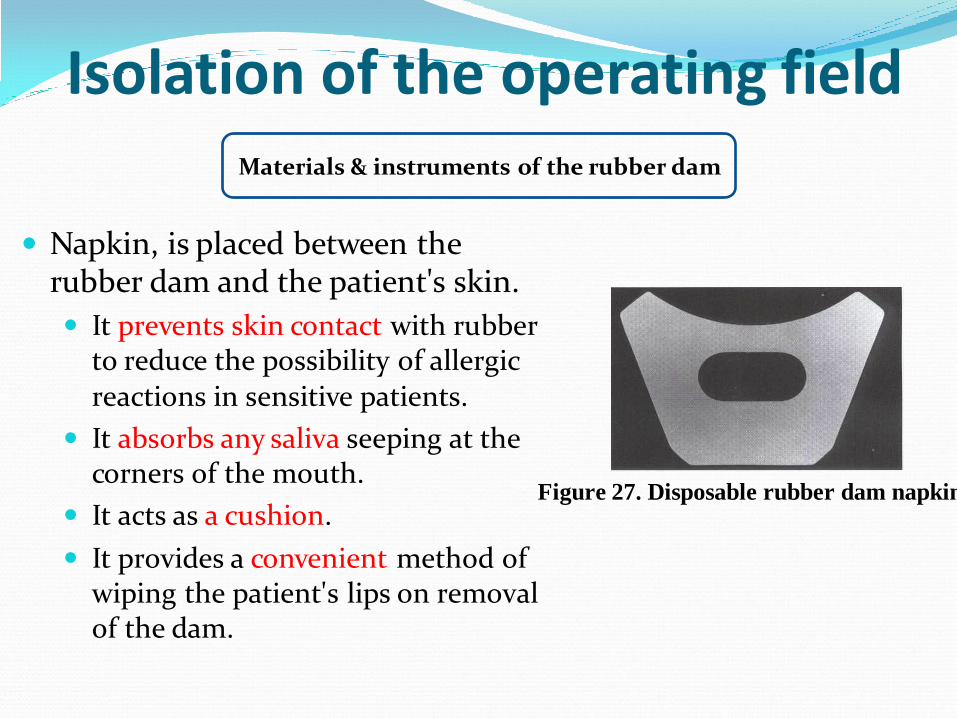
Figure 27. Disposable rubber dam napkin.
Isolation of the operating field
Napkin, is placed between the rubber dam and the patient's skin.
It prevents skin contact with rubber to reduce the possibility of allergic reactions in sensitive patients.
It absorbs any saliva seeping at the corners of the mouth.
It acts as a cushion.
It provides a convenient method of wiping the patient's lips on removal of the dam.
Materials & instruments of the rubber dam

Figure 28. Adjustable neck strap for use with the Young rubber dam frame
Isolation of the operating field Materials & instruments of the rubber dam
Adjustable neck strap (optional) may be placed behind the patient's neck. It is lightly tightened to snug the dam and frame to the face to maximize retraction and provide access to the operating site. It is attached to two hooks, one in the middle of each side of the frame.

Isolation of the operating field Materials & instruments of the rubber dam
Lubricant, water-soluble lubricant applied in the area of the punched holes to facilitate the passing of the dam septa through the proximal contacts. A rubber dam lubricant is commercially available, but other lubricants, such as shaving cream or soap slurry, are also satisfactory. Cocoa butter or petroleum jelly can be used at the corners of the patient's mouth to prevent irritation, but they are not satisfactory rubber dam lubricants.
Figure 29. Rubber dam lubricant.
Isolation of the operating field Materials & instruments of the rubber dam
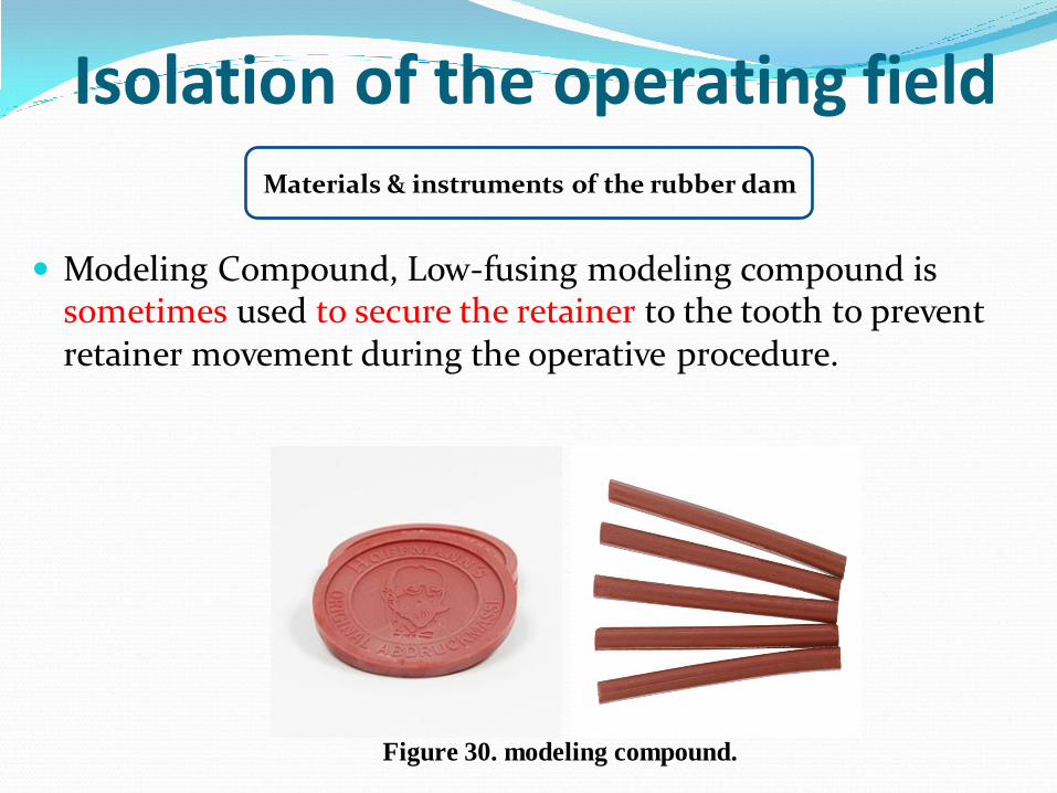
Modeling Compound, Low-fusing modeling compound is sometimes used to secure the retainer to the tooth to prevent retainer movement during the operative procedure.
Figure 30. modeling compound.

Figure 31. A, Anchor formed from dental tape. B, Anchor formed from rubber dam material.
Isolation of the operating field
Anchors (Other Than Retainers), The proximal contact may be sufficient to anchor the dam on the tooth farthest from the posterior retainer (in the isolated field), thereby eliminating the need for a second retainer. To further secure the rubber dam on the tooth farthest from the posterior retainer or to anchor it on any tooth where retainer is not indicated, waxed dental tape (or floss) or a small piece of rubber dam material (cut from a sheet of dam) may be passed through the proximal contact.
Materials & instruments of the rubber dam

Isolation of the operating field Placement of the rubber dam
Method 1: sequential method maximal visibility when placing the retainer, which reduces the risk of
impinging gingival tissue.
according to most operators, it is more simple procedure than other methods.
Method 2: simultaneous method
it reduces the risk of the retainer being swallowed or aspirated.
it solves the occasional difficulty of trying to pass the dam over a previously placed retainer.
Method 3: sequential method
does not have to manipulate the dam over the retainer.
