learning objectivesresource.download.wjec.co.uk.s3.amazonaws.com/vtc/2013-14... · example...
TRANSCRIPT
Topic 4.1 – Introduction
1
Learning Objectives: At the end of this topic you will be able to;
recall that communication is the meaningful information from one location to another;
understand the following terms applied to communications systems’ o analogue and digital signals o transmission medium o carrier o encoding / decoding o modulation / demodulation o gain / attenuation o base (signal) bandwith o broadcast bandwidth o noise / distortion o multiplexer / demultiplexer o time division multiplexing o frequency division multiplexing o error detection / error correction
recall and explain the relationship between bandwidth, data rate and the capacity to carry information.
Module ET4 – Communication Systems
2
This topic will introduce you to the basic principles behind communication systems, and provide clarification of many of the key principles you will meet during the course of this unit. To this extent some of the work contained in this topic may seem unusual to you at the start of the course but will be a useful summary at the end of the whole unit. To this extent you should swap into and out of this unit several times throughout the course as each topic is covered in depth elsewhere.
Introduction to Data Transfer
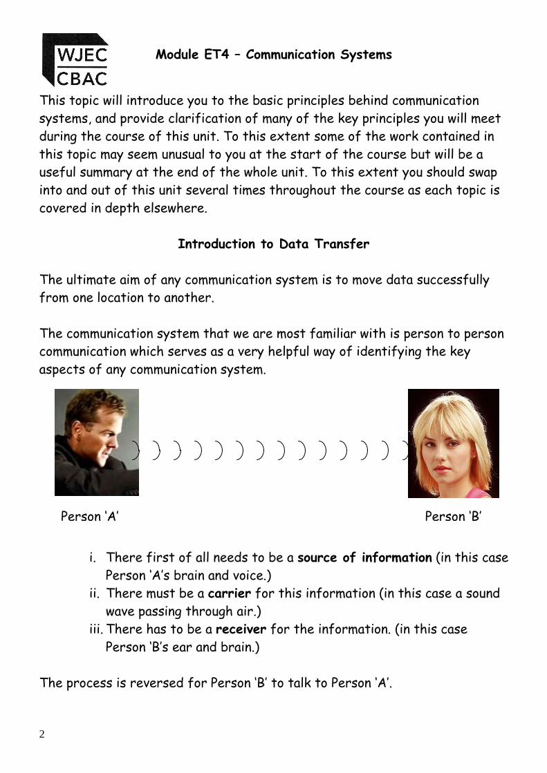
The ultimate aim of any communication system is to move data successfully from one location to another. The communication system that we are most familiar with is person to person communication which serves as a very helpful way of identifying the key aspects of any communication system.
i. There first of all needs to be a source of information (in this case
Person ‘A’s brain and voice.) ii. There must be a carrier for this information (in this case a sound
wave passing through air.) iii. There has to be a receiver for the information. (in this case
Person ‘B’s ear and brain.) The process is reversed for Person ‘B’ to talk to Person ‘A’.
Person ‘A’ Person ‘B’
Topic 4.1 – Introduction
3
If the source of information can only produce a single continuous sound for example ‘shhhh’ then communication between ‘A’ and ‘B’ would not be possible, since the sound never changes. However if it is possible for Person ‘A’ to turn the sound on and off at will, it is then possible to make up a series of codes that provided ‘A’ and ‘B’ know what the codes mean, they can have a basic ‘conversation’. Over the period of many generations language has developed into what it is today and we think nothing of the communication that takes place on a person to person basis. The point of this rather simple explanation is that the most fundamental feature of all communication systems is that, it is impossible to transmit any information unless the carrier is made to vary, i.e. to change or wobble in some way. This change is given the name modulation, and there are many different ways of doing this as we will find out later in this topic. In the simple model that we have looked at here communication is possible over only relatively short distances. The human voice can only carry for short distances in air. In order to transfer a message or ‘data’ over longer distances other carrier systems have been developed. In the early days of communication systems, Indians used smoke signals, in ancient China, soldiers’ lit bonfires on the great wall of China to send warnings of invasion to the emperor. Such signals could travel up to 300 miles in a couple of hours. The telegraph revolutionised communication in America where an electric current switched on and off in one town caused a series of ‘clicks’ from an electromagnet opening and closing in a town many miles away. Samuel Morse in 1843 set up a working telegraph system between Washington and Baltimore (some 60km away), closing a switch in Washington caused a pen to make a mark on a piece of paper. The longer the switch was closed the longer the line on the paper. Morse developed a code for each letter of the alphabet from a series of ‘dots’ and ‘dashes’.
Module ET4 – Communication Systems
4
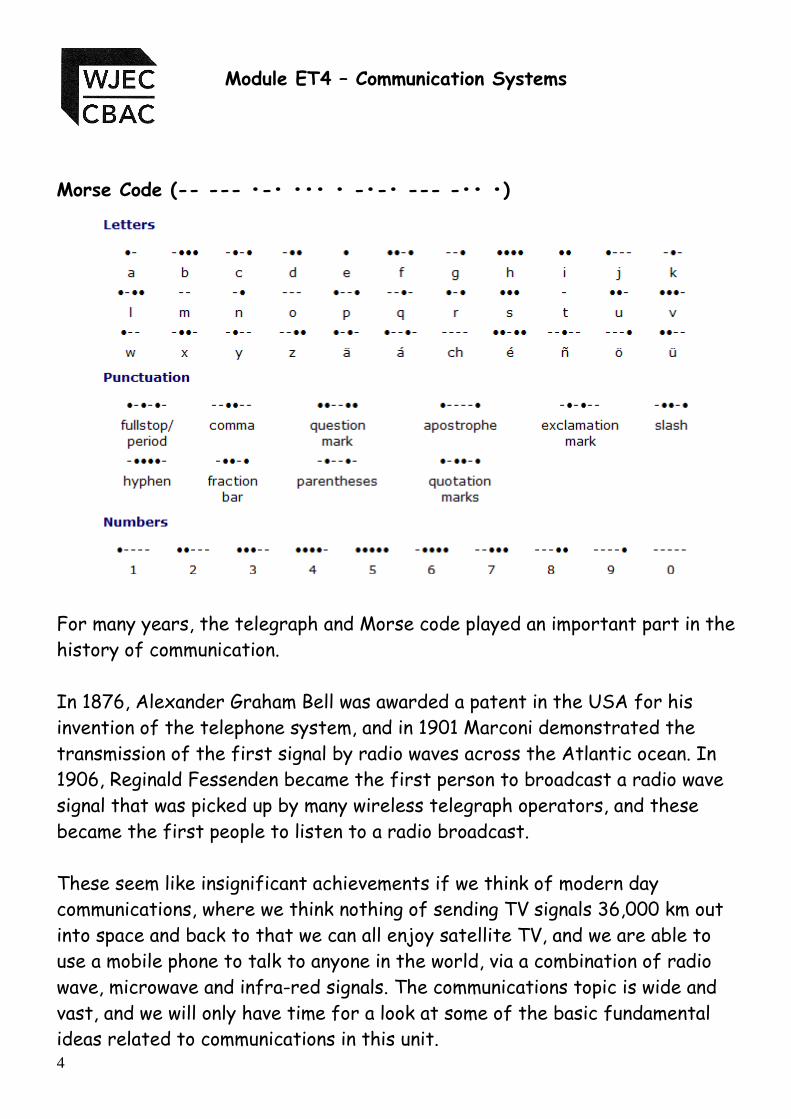
Morse Code (-- --- •-• ••• • -•-• --- -•• •)
For many years, the telegraph and Morse code played an important part in the history of communication. In 1876, Alexander Graham Bell was awarded a patent in the USA for his invention of the telephone system, and in 1901 Marconi demonstrated the transmission of the first signal by radio waves across the Atlantic ocean. In 1906, Reginald Fessenden became the first person to broadcast a radio wave signal that was picked up by many wireless telegraph operators, and these became the first people to listen to a radio broadcast. These seem like insignificant achievements if we think of modern day communications, where we think nothing of sending TV signals 36,000 km out into space and back to that we can all enjoy satellite TV, and we are able to use a mobile phone to talk to anyone in the world, via a combination of radio wave, microwave and infra-red signals. The communications topic is wide and vast, and we will only have time for a look at some of the basic fundamental ideas related to communications in this unit.
Topic 4.1 – Introduction
5
The essential part of a communications system is that the information to be transmitted is attached to a suitable carrier, transmitted, received by the receiver and the original message can be retrieved. A communication system that loses the original information during transmission is not very good! There are many, many terms that form part of the understanding of communication systems and this next section of this topic will try to explain what each of these means, and will form a useful summary to refer to. Your teacher may tell you to skip some parts until they are dealt with in more detail in individual chapters but they have been grouped together here as a useful revision library. 1. Analogue and Digital signals.
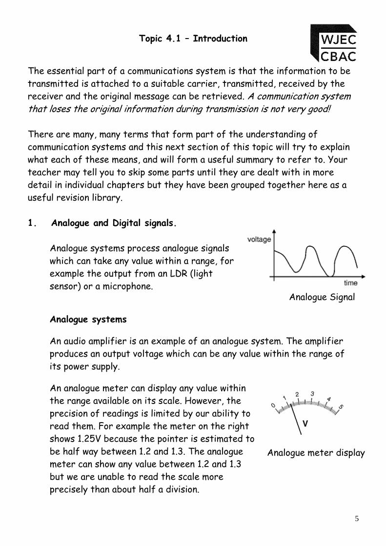
Analogue systems process analogue signals which can take any value within a range, for example the output from an LDR (light sensor) or a microphone.
Analogue systems
An audio amplifier is an example of an analogue system. The amplifier produces an output voltage which can be any value within the range of its power supply.
An analogue meter can display any value within the range available on its scale. However, the precision of readings is limited by our ability to read them. For example the meter on the right shows 1.25V because the pointer is estimated to be half way between 1.2 and 1.3. The analogue meter can show any value between 1.2 and 1.3 but we are unable to read the scale more precisely than about half a division.
Analogue Signal
Analogue meter display
Module ET4 – Communication Systems
6
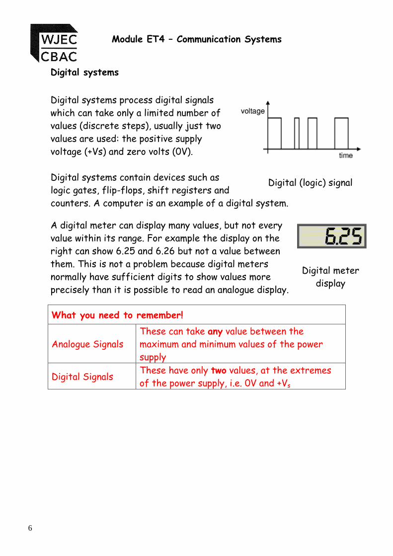
Digital systems Digital systems process digital signals which can take only a limited number of values (discrete steps), usually just two values are used: the positive supply voltage (+Vs) and zero volts (0V). Digital systems contain devices such as logic gates, flip-flops, shift registers and counters. A computer is an example of a digital system.
A digital meter can display many values, but not every value within its range. For example the display on the right can show 6.25 and 6.26 but not a value between them. This is not a problem because digital meters normally have sufficient digits to show values more precisely than it is possible to read an analogue display.
What you need to remember!
Analogue Signals These can take any value between the maximum and minimum values of the power supply
Digital Signals These have only two values, at the extremes of the power supply, i.e. 0V and +Vs
Digital (logic) signal
Digital meter display
Topic 4.1 – Introduction
7
2. Transmission Medium.
A transmission medium (plural transmission media) is a material or substance (solid, liquid or gas) which can propagate energy waves. For example, the transmission medium for sound received by the ears is usually air, but solids and liquids may also act as transmission media for sound.
The vacuum of empty space is also a transmission medium for electromagnetic waves such as light and radio waves.
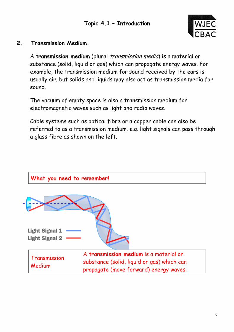
Cable systems such as optical fibre or a copper cable can also be referred to as a transmission medium. e.g. light signals can pass through a glass fibre as shown on the left.
What you need to remember!
Transmission Medium
A transmission medium is a material or substance (solid, liquid or gas) which can propagate (move forward) energy waves.
Module ET4 – Communication Systems
8
3. Carrier
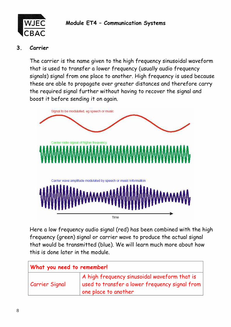
The carrier is the name given to the high frequency sinusoidal waveform that is used to transfer a lower frequency (usually audio frequency signals) signal from one place to another. High frequency is used because these are able to propagate over greater distances and therefore carry the required signal further without having to recover the signal and boost it before sending it on again.
Here a low frequency audio signal (red) has been combined with the high frequency (green) signal or carrier wave to produce the actual signal that would be transmitted (blue). We will learn much more about how this is done later in the module.
What you need to remember!
Carrier Signal A high frequency sinusoidal waveform that is used to transfer a lower frequency signal from one place to another
Topic 4.1 – Introduction
9
4. Encoding / decoding
Encoding is the process of transforming information from one format into another. This can be used to improve the security of transmissions, like having a password to the information. Sky use encoding on their transmissions to your satellite box. All TV channels are transmitted to every subscriber, however only those who have paid the necessary premiums are provided with the necessary code to decode the incoming signal so that the programs can actually be viewed on the television. The codes are stored on the Sky viewing card. Temporary codes can be provided via your telephone line for one off events like Sky Box Office, or major sports events like Boxing. This upgrade usually takes just a few seconds to complete. Once the event is over the code is disabled and the channel is once again blocked.
For encoding to be successful both the transmitter and receiver must be aware of the code, otherwise the data cannot be retrieved.
What you need to remember!
Encoding Adding additional information to hide / obscure the original message from general viewing.
Decoding Retrieving a hidden message from an encoded signal
Module ET4 – Communication Systems
10
5. Modulation / demodulation
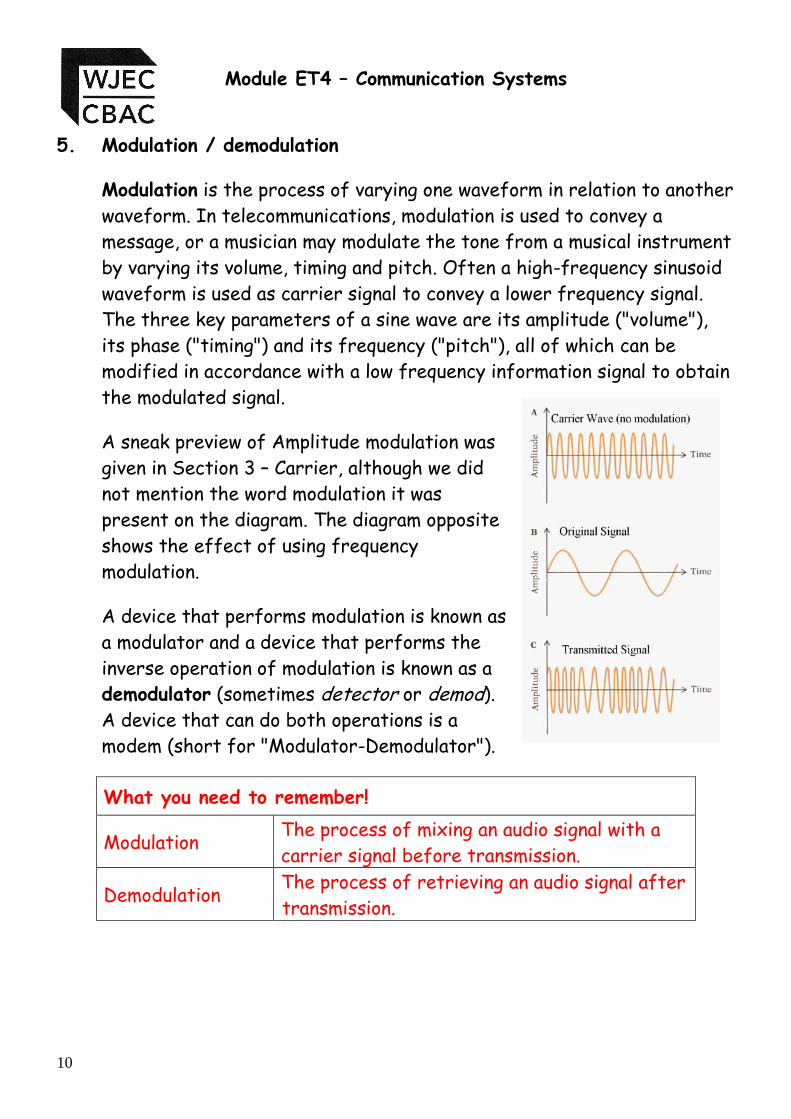
Modulation is the process of varying one waveform in relation to another waveform. In telecommunications, modulation is used to convey a message, or a musician may modulate the tone from a musical instrument by varying its volume, timing and pitch. Often a high-frequency sinusoid waveform is used as carrier signal to convey a lower frequency signal. The three key parameters of a sine wave are its amplitude ("volume"), its phase ("timing") and its frequency ("pitch"), all of which can be modified in accordance with a low frequency information signal to obtain the modulated signal.
A sneak preview of Amplitude modulation was given in Section 3 – Carrier, although we did not mention the word modulation it was present on the diagram. The diagram opposite shows the effect of using frequency modulation.
A device that performs modulation is known as a modulator and a device that performs the inverse operation of modulation is known as a demodulator (sometimes detector or demod). A device that can do both operations is a modem (short for "Modulator-Demodulator").
What you need to remember!
Modulation The process of mixing an audio signal with a carrier signal before transmission.
Demodulation The process of retrieving an audio signal after transmission.
Topic 4.1 – Introduction
11
6. Gain / attenuation
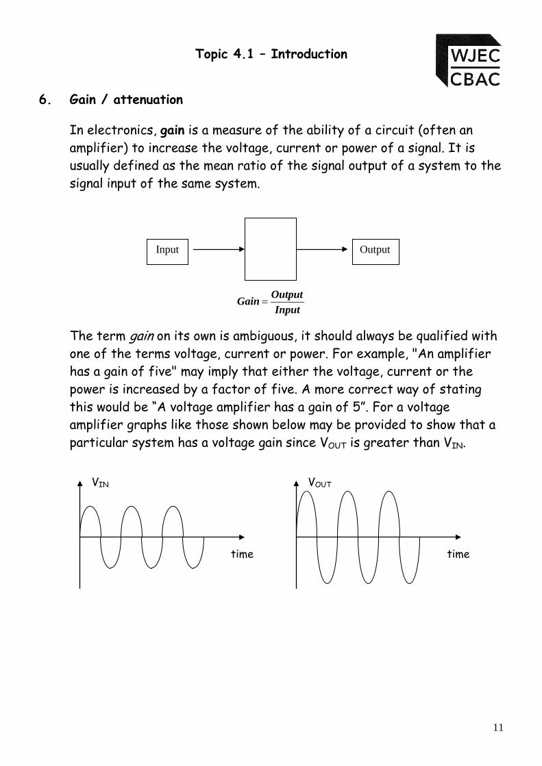
In electronics, gain is a measure of the ability of a circuit (often an amplifier) to increase the voltage, current or power of a signal. It is usually defined as the mean ratio of the signal output of a system to the signal input of the same system.
The term gain on its own is ambiguous, it should always be qualified with one of the terms voltage, current or power. For example, "An amplifier has a gain of five" may imply that either the voltage, current or the power is increased by a factor of five. A more correct way of stating this would be “A voltage amplifier has a gain of 5”. For a voltage amplifier graphs like those shown below may be provided to show that a particular system has a voltage gain since VOUT is greater than VIN.
VIN VOUT
time time
Input Output
InputOutputGain =
Module ET4 – Communication Systems
12
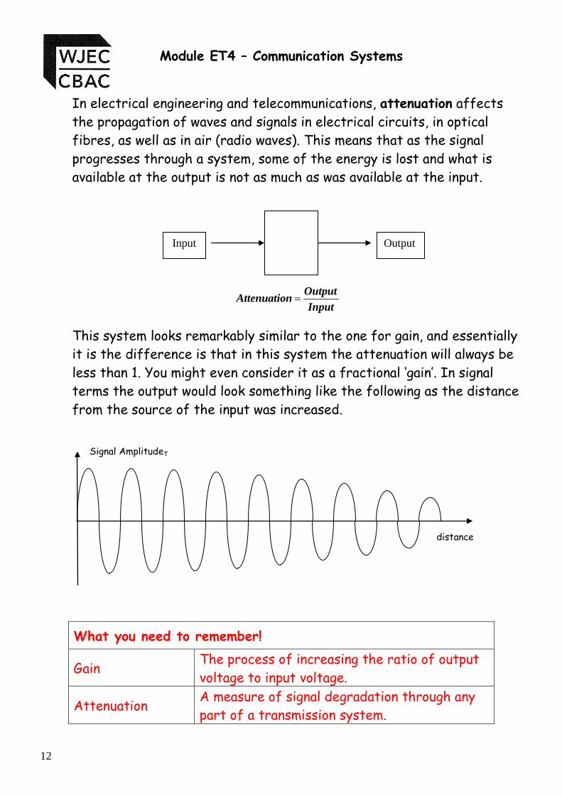
In electrical engineering and telecommunications, attenuation affects the propagation of waves and signals in electrical circuits, in optical fibres, as well as in air (radio waves). This means that as the signal progresses through a system, some of the energy is lost and what is available at the output is not as much as was available at the input.
This system looks remarkably similar to the one for gain, and essentially it is the difference is that in this system the attenuation will always be less than 1. You might even consider it as a fractional ‘gain’. In signal terms the output would look something like the following as the distance from the source of the input was increased.
What you need to remember!
Gain The process of increasing the ratio of output voltage to input voltage.
Attenuation A measure of signal degradation through any part of a transmission system.
Signal AmplitudeT
distance
Input Output
InputOutputnAttenuatio =
Topic 4.1 – Introduction
13
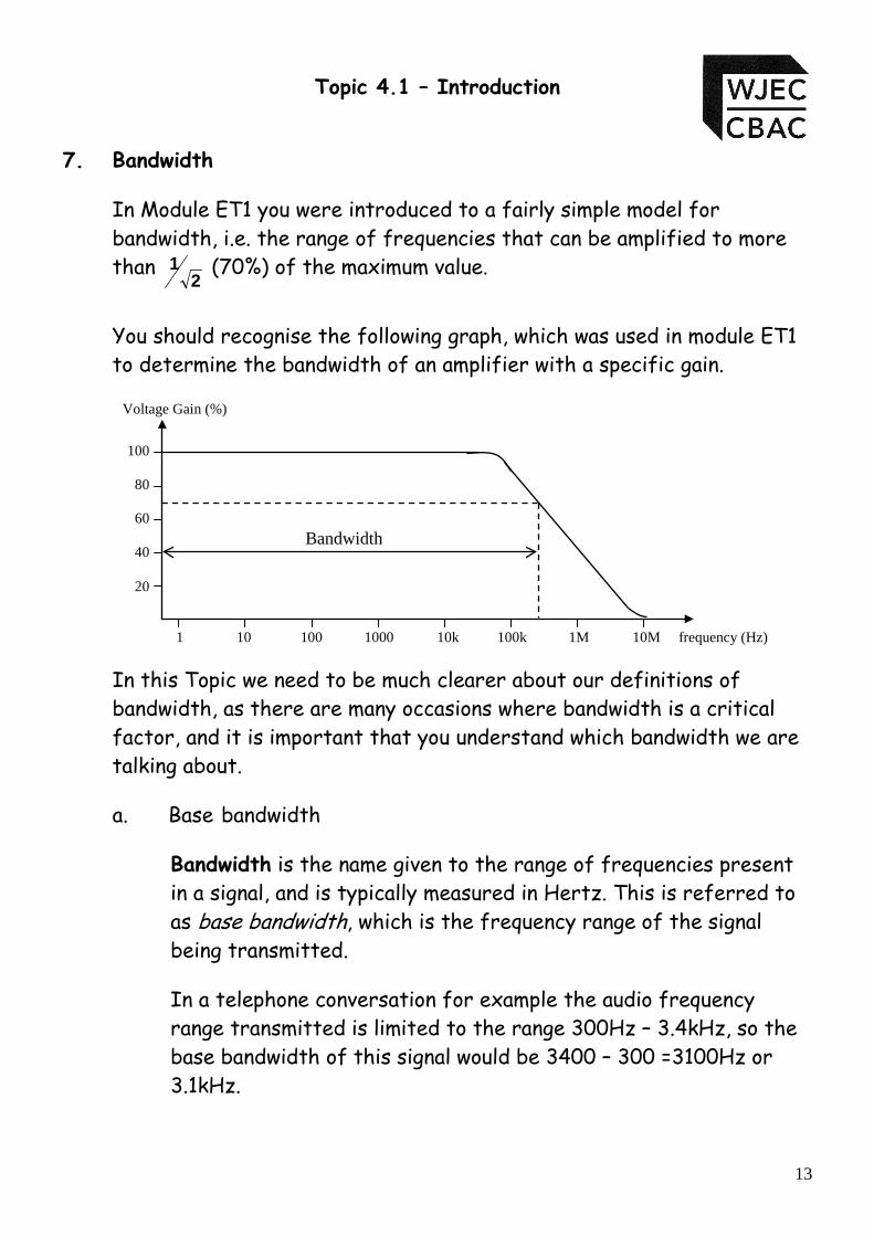
7. Bandwidth
In Module ET1 you were introduced to a fairly simple model for bandwidth, i.e. the range of frequencies that can be amplified to more than
21 (70%) of the maximum value.
You should recognise the following graph, which was used in module ET1
to determine the bandwidth of an amplifier with a specific gain. In this Topic we need to be much clearer about our definitions of
bandwidth, as there are many occasions where bandwidth is a critical factor, and it is important that you understand which bandwidth we are talking about.
a. Base bandwidth
Bandwidth is the name given to the range of frequencies present in a signal, and is typically measured in Hertz. This is referred to as base bandwidth, which is the frequency range of the signal being transmitted.
In a telephone conversation for example the audio frequency range transmitted is limited to the range 300Hz – 3.4kHz, so the base bandwidth of this signal would be 3400 – 300 =3100Hz or 3.1kHz.
1 10 100 1000 10k 100k 1M 10M frequency (Hz)
100
80
60
40
20
Voltage Gain (%)
Bandwidth
Module ET4 – Communication Systems
14
For an amplitude modulated radio station the base bandwidth is kept to about 5kHz. A frequency modulated radio station however might use a base bandwidth of 15kHz. A television signal on the other hand requires a base bandwidth of 5.5MHz.
The requirement for increasing the bandwidth is a reflection of the amount of information to be carried by the signal. A television picture for example contains significantly more information than a simple telephone conversation, and therefore requires a much larger base bandwidth.
b. Broadcast Bandwidth
Broadcast bandwidth is the range of frequencies that require to be transmitted after a modulation process has taken place. The type of modulation used will affect the bandwidth needed to transmit the information. For example amplitude modulation requires doubles the base bandwidth of the signal, frequency modulation requires a much higher broadcast bandwidth of the order of 200kHz.
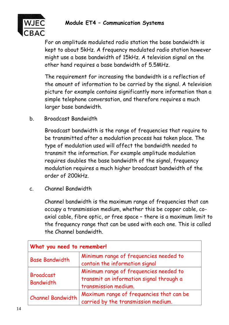
c. Channel Bandwidth
Channel bandwidth is the maximum range of frequencies that can occupy a transmission medium, whether this be copper cable, co-axial cable, fibre optic, or free space – there is a maximum limit to the frequency range that can be used with each one. This is called the Channel bandwidth.
What you need to remember!
Base Bandwidth Minimum range of frequencies needed to contain the information signal
Broadcast Bandwidth
Minimum range of frequencies needed to transmit an information signal through a transmission medium.
Channel Bandwidth Maximum range of frequencies that can be carried by the transmission medium.
Topic 4.1 – Introduction
15
8. Noise / Distortion
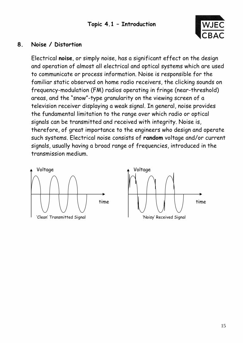
Electrical noise, or simply noise, has a significant effect on the design and operation of almost all electrical and optical systems which are used to communicate or process information. Noise is responsible for the familiar static observed on home radio receivers, the clicking sounds on frequency-modulation (FM) radios operating in fringe (near-threshold) areas, and the “snow”-type granularity on the viewing screen of a television receiver displaying a weak signal. In general, noise provides the fundamental limitation to the range over which radio or optical signals can be transmitted and received with integrity. Noise is, therefore, of great importance to the engineers who design and operate such systems. Electrical noise consists of random voltage and/or current signals, usually having a broad range of frequencies, introduced in the transmission medium.
Voltage Voltage
time time
‘Clean’ Transmitted Signal ‘Noisy’ Received Signal
Module ET4 – Communication Systems
16
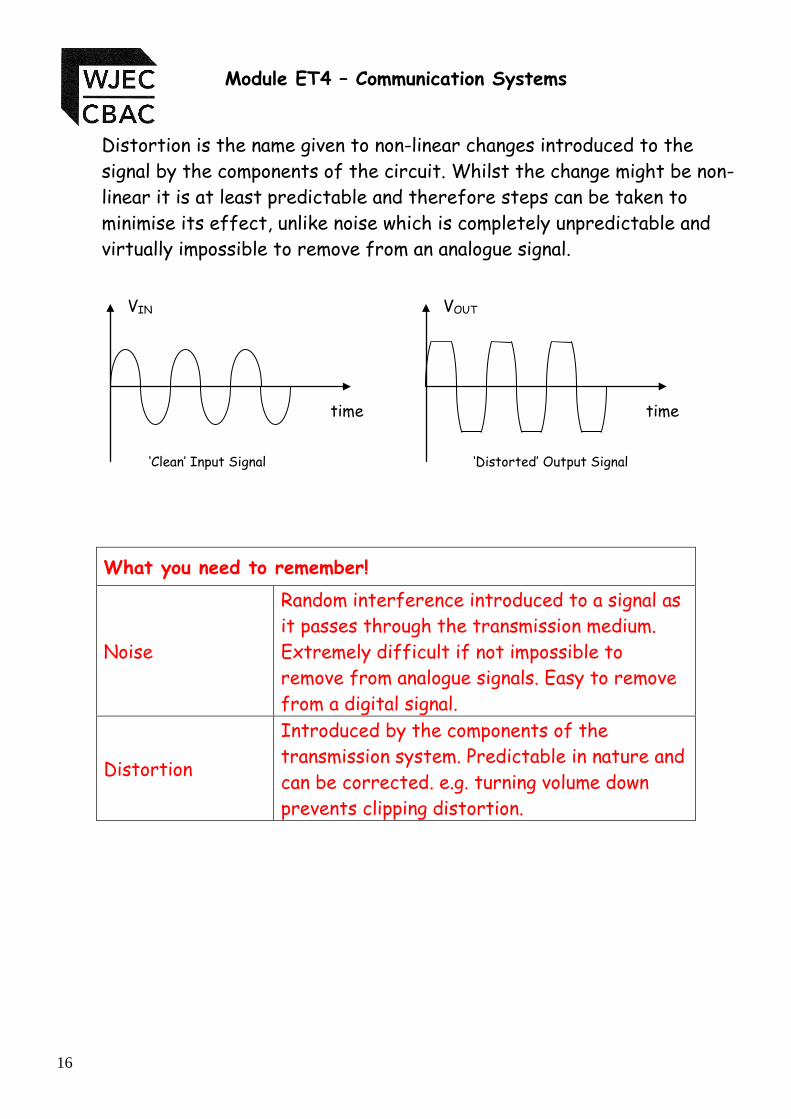
Distortion is the name given to non-linear changes introduced to the signal by the components of the circuit. Whilst the change might be non-linear it is at least predictable and therefore steps can be taken to minimise its effect, unlike noise which is completely unpredictable and virtually impossible to remove from an analogue signal.
What you need to remember!
Noise
Random interference introduced to a signal as it passes through the transmission medium. Extremely difficult if not impossible to remove from analogue signals. Easy to remove from a digital signal.
Distortion
Introduced by the components of the transmission system. Predictable in nature and can be corrected. e.g. turning volume down prevents clipping distortion.
VIN VOUT
time time
‘Clean’ Input Signal ‘Distorted’ Output Signal
Topic 4.1 – Introduction
17
9. Multiplexing
This is the process of allowing several independent users to share the same transmission medium (or link). The medium can be a cable (i.e. wire-pair, co-axial, optic fibre) or the atmosphere (or space). An information pathway within this medium is called a channel. By means of multiplexing, many channels can be accommodated within one single medium.
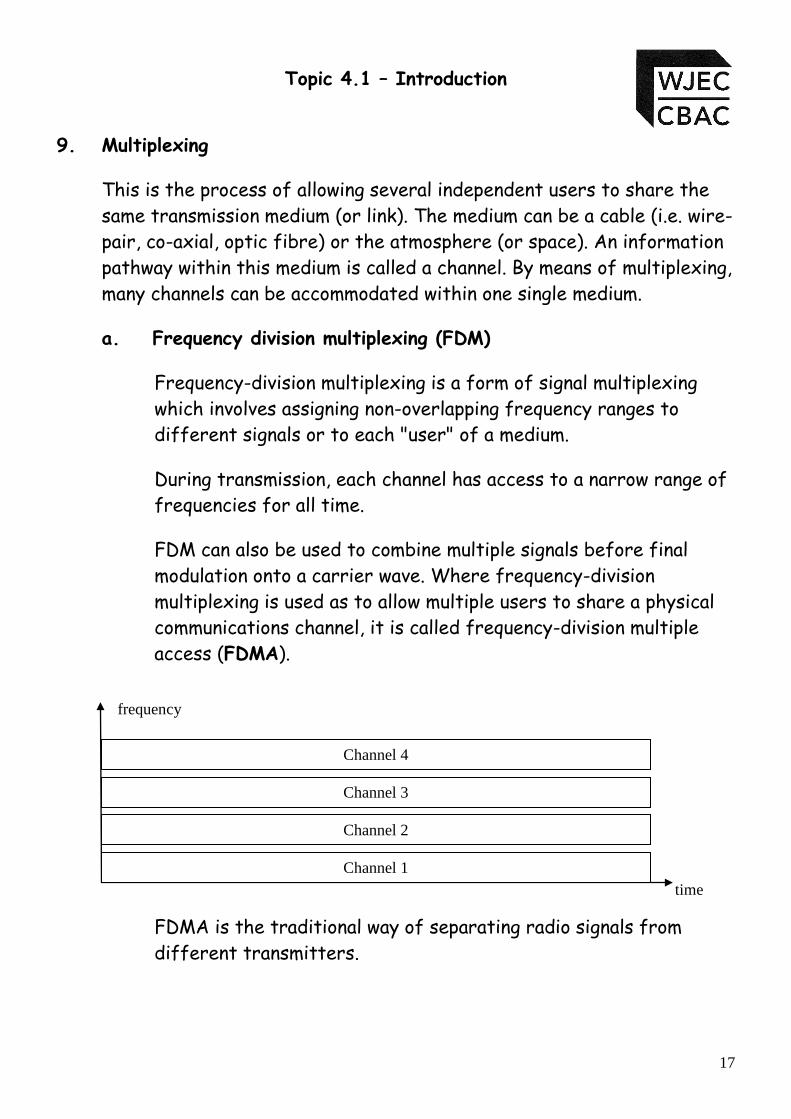
a. Frequency division multiplexing (FDM)
Frequency-division multiplexing is a form of signal multiplexing which involves assigning non-overlapping frequency ranges to different signals or to each "user" of a medium.
During transmission, each channel has access to a narrow range of frequencies for all time.
FDM can also be used to combine multiple signals before final modulation onto a carrier wave. Where frequency-division multiplexing is used as to allow multiple users to share a physical communications channel, it is called frequency-division multiple access (FDMA).
FDMA is the traditional way of separating radio signals from different transmitters.
Channel 1
Channel 2
Channel 3
Channel 4
time
frequency
Module ET4 – Communication Systems
18
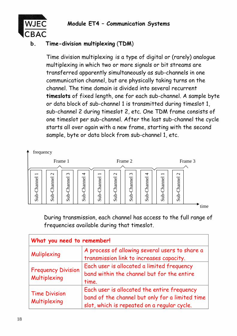
b. Time-division multiplexing (TDM)
Time division multiplexing is a type of digital or (rarely) analogue multiplexing in which two or more signals or bit streams are transferred apparently simultaneously as sub-channels in one communication channel, but are physically taking turns on the channel. The time domain is divided into several recurrent timeslots of fixed length, one for each sub-channel. A sample byte or data block of sub-channel 1 is transmitted during timeslot 1, sub-channel 2 during timeslot 2, etc. One TDM frame consists of one timeslot per sub-channel. After the last sub-channel the cycle starts all over again with a new frame, starting with the second sample, byte or data block from sub-channel 1, etc.
During transmission, each channel has access to the full range of frequencies available during that timeslot.
What you need to remember!
Muliplexing A process of allowing several users to share a transmission link to increases capacity.
Frequency Division Multiplexing
Each user is allocated a limited frequency band within the channel but for the entire time.
Time Division Multiplexing
Each user is allocated the entire frequency band of the channel but only for a limited time slot, which is repeated on a regular cycle.
Sub-
Cha
nnel
1
Sub-
Cha
nnel
2
Sub-
Cha
nnel
3
Sub-
Cha
nnel
4
Sub-
Cha
nnel
1
Sub-
Cha
nnel
2
Sub-
Cha
nnel
3
Sub-
Cha
nnel
4
Sub-
Cha
nnel
1
Sub-
Cha
nnel
2
time
Frame 1 Frame 2 Frame 3
frequency
Topic 4.1 – Introduction
19
10. Multiplexer / demultiplexer
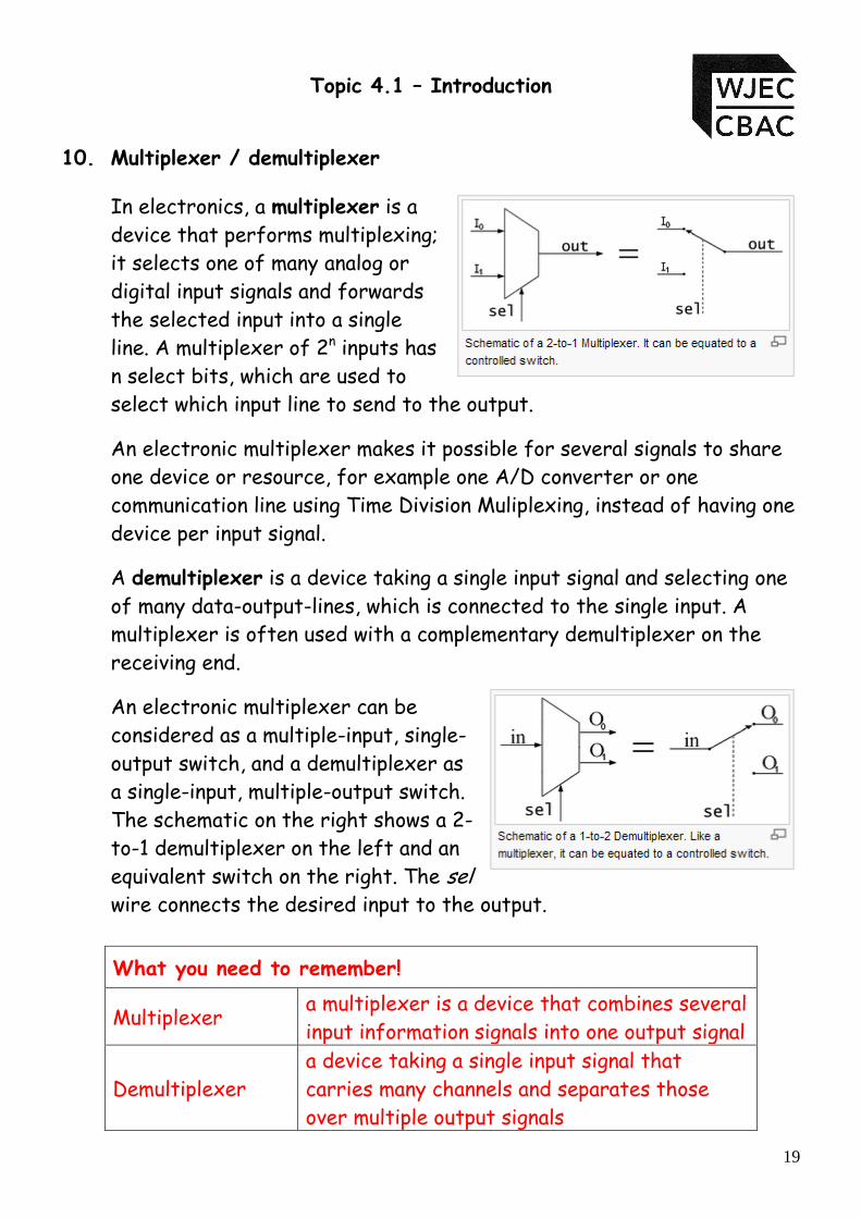
In electronics, a multiplexer is a device that performs multiplexing; it selects one of many analog or digital input signals and forwards the selected input into a single line. A multiplexer of 2n inputs has n select bits, which are used to select which input line to send to the output.
An electronic multiplexer makes it possible for several signals to share one device or resource, for example one A/D converter or one communication line using Time Division Muliplexing, instead of having one device per input signal.
A demultiplexer is a device taking a single input signal and selecting one of many data-output-lines, which is connected to the single input. A multiplexer is often used with a complementary demultiplexer on the receiving end.
An electronic multiplexer can be considered as a multiple-input, single-output switch, and a demultiplexer as a single-input, multiple-output switch. The schematic on the right shows a 2-to-1 demultiplexer on the left and an equivalent switch on the right. The sel wire connects the desired input to the output. What you need to remember!
Multiplexer a multiplexer is a device that combines several input information signals into one output signal
Demultiplexer a device taking a single input signal that carries many channels and separates those over multiple output signals
Module ET4 – Communication Systems
20
11. Error detection / error correction
Error-detection is the name given to a digital technique that can be used to check if a transmitted signal is actually received correctly. It requires additional information in the form of parity bits to be transmitted along with the data. If the test fails then a signal can be sent to the transmitter to resend the data.
Error-correction is a more sophisticated system employed during digital transmissions, which not only detects that an error has been received, but is capable of locating and changing the data to prevent having to retransmit the data again, therefore saving time. Additional data bits have to be transmitted however so there is a trade off between the time to transmit the additional information and the importance of having to correct errors in real time.
What you need to remember!
Error detection The ability to detect that an error has occurred during a digital transmission
Error correction The ability to detect and correct an error that has occurred during a digital transmission.
You will cover these areas in much more detail in the following topics and this should provide a useful reference section to check the meanings of some of the principle terms used within the communications field.
Topic 4.1 – Introduction
21
Capacity of the Transmission Channel
It is important to realise that that there is a limit to how much information can be carried by a particular communication channel, whether this be a copper wire, a fibre optic cable, or a radio frequency band like MW or LW.
Channel capacity is the tightest upper bound on the amount of information that can be reliably transmitted over a communications channel. The channel capacity of a given channel is the maximum information rate (in units of information per unit time) that can be achieved with a very small error probability. The channel capacity is governed by three key factors:
i. Bandwidth of the channel available
ii. Power of signal
iii. Power of noise
As this area of communications becomes highly mathematical, we will not pursue these in any detail. It will be sufficient for the purposes of this introductory communications course that you are aware of the limiting factors on channel capacity. In an examination you would be asked to give no more than two of these three factors that affect the capacity of a transmission channel.
Module ET4 – Communication Systems
22
Examination Style Questions.
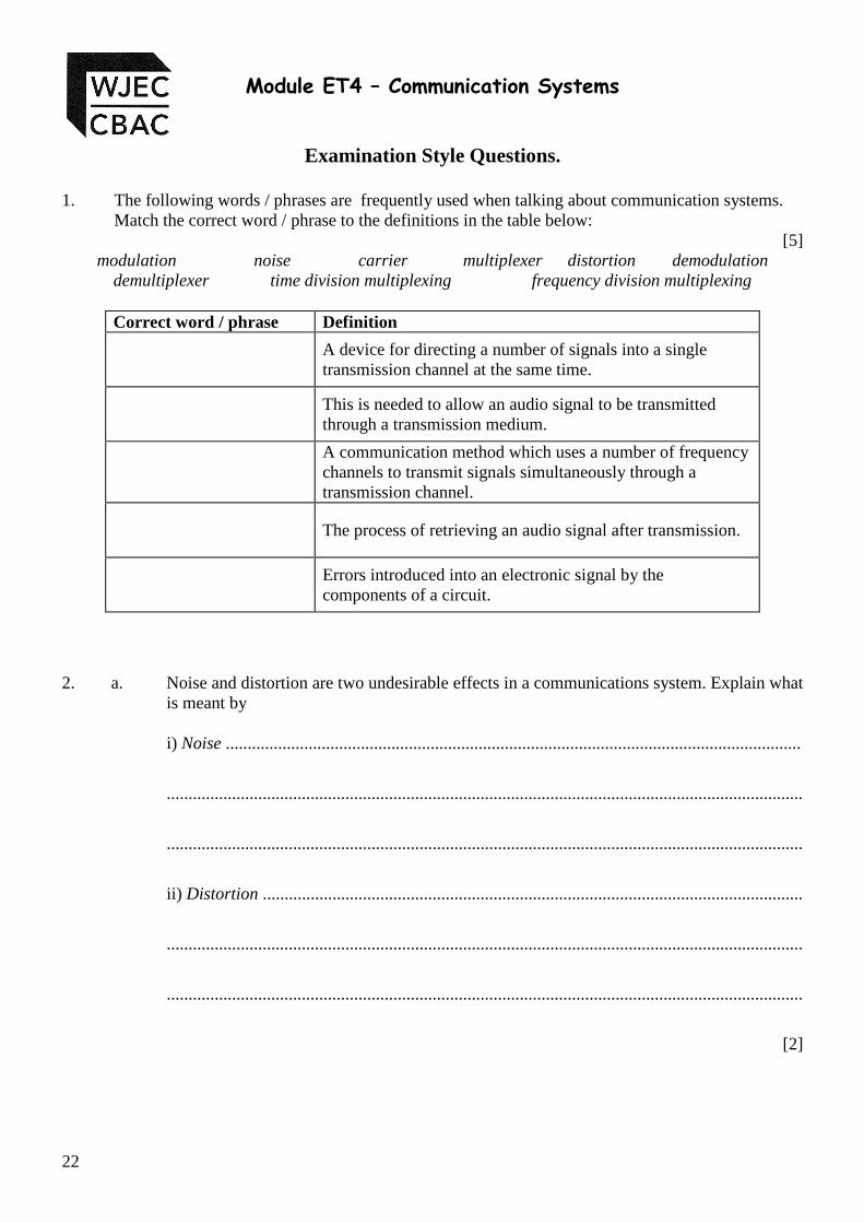
1. The following words / phrases are frequently used when talking about communication systems. Match the correct word / phrase to the definitions in the table below:
[5] modulation noise carrier multiplexer distortion demodulation
demultiplexer time division multiplexing frequency division multiplexing
Correct word / phrase Definition
A device for directing a number of signals into a single transmission channel at the same time.
This is needed to allow an audio signal to be transmitted through a transmission medium.
A communication method which uses a number of frequency channels to transmit signals simultaneously through a transmission channel.
The process of retrieving an audio signal after transmission.
Errors introduced into an electronic signal by the components of a circuit.
2. a. Noise and distortion are two undesirable effects in a communications system. Explain what
is meant by i) Noise ....................................................................................................................................
..................................................................................................................................................
..................................................................................................................................................
ii) Distortion ............................................................................................................................
..................................................................................................................................................
..................................................................................................................................................
[2]
Topic 4.1 – Introduction
23
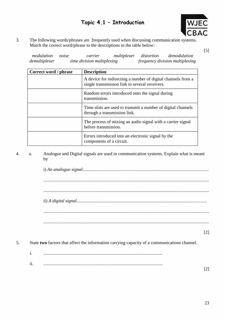
3. The following words/phrases are frequently used when discussing communication systems. Match the correct word/phrase to the descriptions in the table below:
[5] modulation noise carrier multiplexer distortion demodulation
demultiplexer time division multiplexing frequency division multiplexing
Correct word / phrase Description
A device for redirecting a number of digital channels from a single transmission link to several receivers.
Random errors introduced onto the signal during transmission.
Time slots are used to transmit a number of digital channels through a transmission link.
The process of mixing an audio signal with a carrier signal before transmission.
Errors introduced into an electronic signal by the components of a circuit.
4. a. Analogue and Digital signals are used in communication systems. Explain what is meant
by i) An analogue signal...............................................................................................................
..................................................................................................................................................
..................................................................................................................................................
ii) A digital signal...................................................................................................................
..................................................................................................................................................
..................................................................................................................................................
[2]
5. State two factors that affect the information carrying capacity of a communications channel. i. ......................................................................................................... ii. .........................................................................................................
[2]
Module ET4 – Communication Systems
24
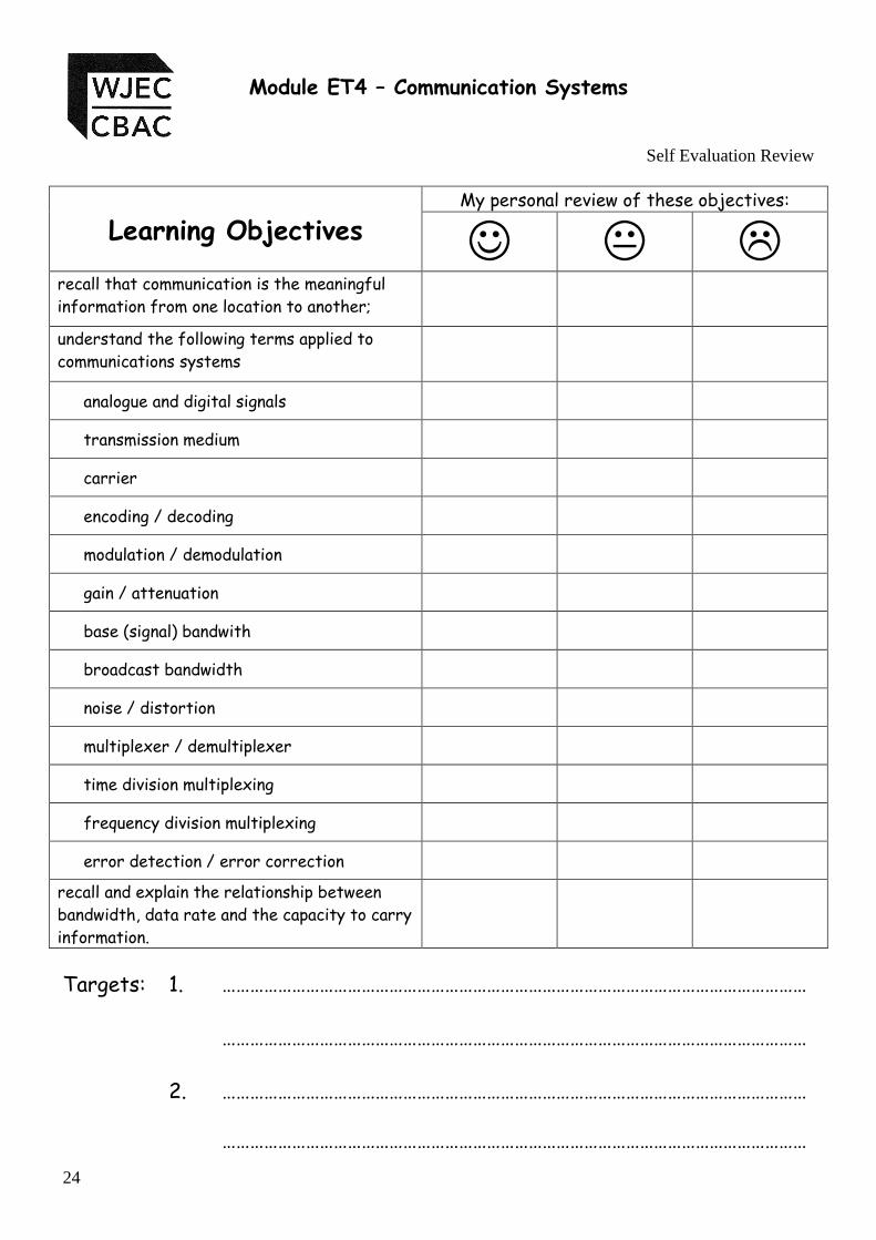
Self Evaluation Review
Learning Objectives My personal review of these objectives:
recall that communication is the meaningful information from one location to another;
understand the following terms applied to communications systems
analogue and digital signals
transmission medium
carrier
encoding / decoding
modulation / demodulation
gain / attenuation
base (signal) bandwith
broadcast bandwidth
noise / distortion
multiplexer / demultiplexer
time division multiplexing
frequency division multiplexing
error detection / error correction
recall and explain the relationship between bandwidth, data rate and the capacity to carry information.
Targets: 1. ……………………………………………………………………………………………………………… ………………………………………………………………………………………………………………
2. ………………………………………………………………………………………………………………
………………………………………………………………………………………………………………