learner workbook version 1 - vetres current machines... · learner workbook version 1. ......
TRANSCRIPT
Learner Workbook
Version 1
Training and Education SupportIndustry Skills Unit
Meadowbank
Product Code: 5633
Alternating Current Machines
SAMPLE

First published in December 2012 byTraining and Education Support, Industry Skills Unit, MeadowbankLevel 3, Building J, See StreetMeadowbank NSW 2114
©
New South Wales Technical and Further Education Commission 2012
ISBN 978-1-74236-355-4
Alternating Current Machines
FEEDBACK
We value your opinion and welcome suggestions on how we could improve this resource manual. Keep in mind that the manual is intended to help students learn and is not a text book.
Send your comments and suggestions to:Program ManagerTraining and Education Support, Industry Skills Unit, MeadowbankLevel 3, Building J, See StreetMeadowbank NSW 2114Ph: 02 9942 3200Fax: 02 9942 3257
SAMPLE
Alternating Current Machines
© TAFE NSW (Training & Education Support, Industry Skills Unit Meadowbank) 2012
ContentsIntroduction ................................................................................... 5
Section 1: Operating Principles of Three-Phase Induction Motors 7
Section 2: Three-Phase Induction Motor Construction ................ 23
Section 3: Three-Phase Induction Motor Characteristics ............ 37
Section 4: Single Phase Motors – Split Phase ............................. 67
Section 5: Single Phase Motors - Capacitor & Shaded Pole Type . 81
Section 6: Revision, Consolidation and Assessment 1 ................. 95
Section 7: Single Phase Motors - Series Universal .................... 105
Section 8: Three Phase Induction Motor Starters ..................... 117
Section 9: Reduced Voltage Three-Phase Induction Motor Starters ...................................................................................135
Section 10: Braking and Rotation Reversal of Three-Phase Induction Motors ..................................................................... 163
Section 11: Motor Speed Control ............................................... 181
Section 12: Revision, Consolidation and Assessment 2 ............... 195
Section 13: Motor Protection ..................................................... 205
Section 14: Three-Phase Synchronous Machines - Operating Principles and Construction ..................................... 227
Section 15: Alternators and Generators ...................................... 237
Section 16: Three-Phase Synchronous Motors ............................ 255
Section 17: Single Phase Synchronous Motors ........................... 269
Section 18: Revision, Consolidation and Assessment 3 .............. 275
Review Questions - Answers ...................................................... 290
Sample Theory Test 1 - Answers ................................................ 306
Sample Theory Test 2 - Answers ................................................ 308
Sample Theory Test 3 - Answers ................................................ 310
SAMPLE

Alternating Current Machines
© TAFE NSW (Training & Education Support, Industry Skills Unit Meadowbank) 2012
SAMPLE

Alternating Current Machines
© TAFE NSW (Training & Education Support, Industry Skills Unit Meadowbank) 2012
IntroductionThis learner workbook contains learning exercises, review questions and sample assessment instruments. It is intended to help students learn and is not a textbook.
ReferencesThe following textbooks are recommended for this module:
• Jenneson J.R., 2010, Electrical Principles for the Electrical Trades, 6th Ed., McGraw-Hill, Sydney.
• Hampson, J., 2011, Electrical Trade Principles - A Practical Approach, 2nd Ed Pearson Education, Sydney.
• Phillips P., 2012, Electrical Principles, 2nd Ed, Cengage Learning, Melbourne.
Other References
• Wildi, T., 1991, Electrical Machines, Drives and Power Systems, 2nd Ed., Prentice Hall, USA.
• AS/NZS 3000:2007 Wiring Rules, Standards Australia, NSW.
• Local Supply Authority Service Rules.
Risk Assessment Terminology
Supervision Level:
D Direct
This means the personal supervision of a learner, at all times, on a direct and constant basis, within visual contact and/or earshot. Constant basis refers to the continuous supervision of tasks being performed for the first time and until skillis demonstrated for the complexity of the task and work environment.
G General
This means the learner does not require constant attendance of the supervisor but requires personal contact with an experienced worker on a recurrent basis when working. Periodic supervision means being under instruction and direction for tasks being formed with checks and tests being made prior to the commissioning of apparatus/equipment.
B Broad
This means the learner does not require constant supervision but requires personal contact with an experienced worker on at least a regular/occasional basis when working. Occasional supervision means being under instruction and direction with checks being carried out on completion of multi-tasks.
Risk Classes:A high risk Potential death or permanent disablement.B medium risk Potential serious injury/illness and temporary disablement.C low risk Potential minor injury, no lost time.
SAMPLE

Alternating Current Machines
© TAFE NSW (Training & Education Support, Industry Skills Unit Meadowbank) 2012
Notes
SAMPLE

Alternating Current Machines
© TAFE NSW (Training & Education Support, Industry Skills Unit Meadowbank) 2012 Page 7 of 316
Section 1: Operating Principles of Three-Phase Induction Motors PurposeIn this section you will learn about the fundamental principles of operation of three-phase induction motors.
ObjectivesAt the end of this section you should be able to:
• apply the right hand (grip) rule for conductors and solenoids and Fleming’s left and right hand rules to determine circuit operating characteristics
• listthecharacteristicsofthemagneticfieldproducedbyasingle,twoandthree-phase winding
• calculatethespeedofrotationofarotatingmagneticfield
• calculate the rotor speed, slip and rotor frequency
• describe the basic principle of operation of an induction motor
• reverse the direction of rotation of a three-phase induction motor.
References
• Jenneson J.R., 2010, Electrical Principles for the Electrical Trades, 6th Ed., McGraw-Hill, Sydney.
• Hampson, J., 2011, Electrical Trade Principles - A Practical Approach, 2nd Ed Pearson Education, Sydney.
• Phillips P., 2012, Electrical Principles, 2nd Ed, Cengage Learning, Melbourne.
• Wildi, T., 1991, Electrical Machines, Drives and Power Systems, 2nd Ed., Prentice Hall, USA.SAMPLE

Alternating Current Machines
Page 8 of 316 © TAFE NSW (Training & Education Support, Industry Skills Unit Meadowbank) 2012
Notes
SAMPLE

Alternating Current Machines
© TAFE NSW (Training & Education Support, Industry Skills Unit Meadowbank) 2012 Page 9 of 316
Learner ExercisesLearner Exercise 1.1
Usingtheright-handconductorrule,andtheconventionalsymbolsforcurrentflow,showthedirectionofcurrentflowandthemagneticfielddirection.
Figure 1.1
Learner Exercise 1.2
Usingtheright-handsolenoidrule,indicateonthediagramthemagneticfieldpolarity of the coils drawn below.
Figure 1.2
Learner Exercise 1.3
UseFleming’sleft-handruletodeterminedirectionofforce,fieldpolarityordirectionofcurrentflowinthediagramsbelow:
N
S
force force
S
N
direction offorce ?
fieldpolarity ?
direction ofcurrent flow ?
Figure 1.3
SAMPLE
Alternating Current Machines
Page 10 of 316 © TAFE NSW (Training & Education Support, Industry Skills Unit Meadowbank) 2012
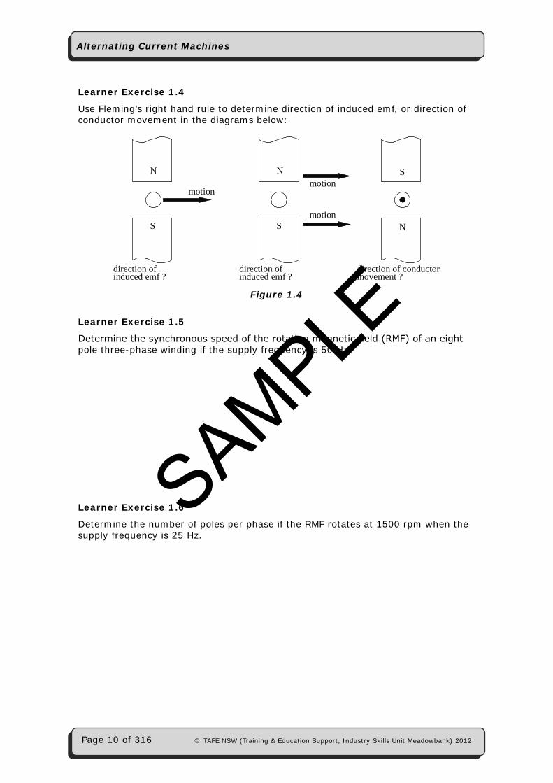
Learner Exercise 1.4
Use Fleming’s right hand rule to determine direction of induced emf, or direction of conductor movement in the diagrams below:
N
S
S
N
direction ofinduced emf ?
direction of conductormovement ?
motionmotion
motion
N
S
direction ofinduced emf ?
Figure 1.4
Learner Exercise 1.5
Determinethesynchronousspeedoftherotatingmagneticfield(RMF)ofaneightpole three-phase winding if the supply frequency is 50 Hz.
Learner Exercise 1.6
Determine the number of poles per phase if the RMF rotates at 1500 rpm when the supply frequency is 25 Hz.
SAMPLE
Alternating Current Machines
© TAFE NSW (Training & Education Support, Industry Skills Unit Meadowbank) 2012 Page 11 of 316
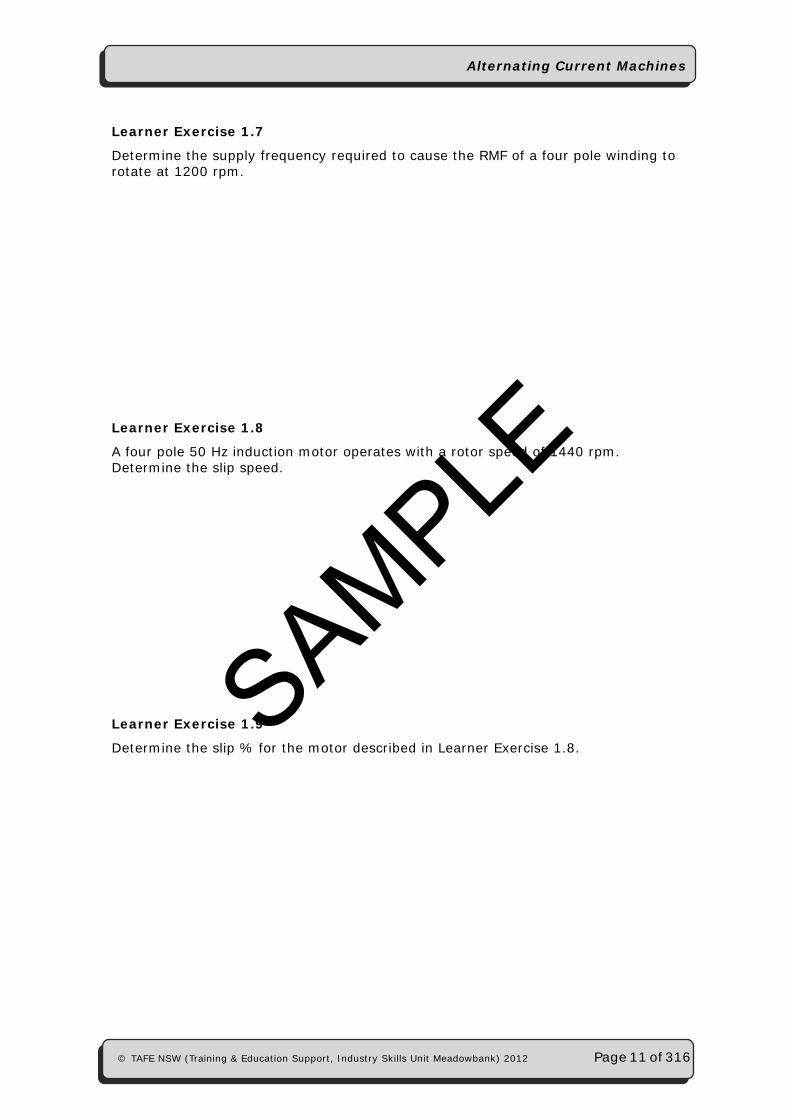
Learner Exercise 1.7
Determine the supply frequency required to cause the RMF of a four pole winding to rotate at 1200 rpm.
Learner Exercise 1.8
A four pole 50 Hz induction motor operates with a rotor speed of 1440 rpm. Determine the slip speed.
Learner Exercise 1.9
Determine the slip % for the motor described in Learner Exercise 1.8.SAMPLE
Alternating Current Machines
Page 12 of 316 © TAFE NSW (Training & Education Support, Industry Skills Unit Meadowbank) 2012
Learner Exercise 1.10
An induction motor operates with a 2% slip. If the synchronous speed of this motor is 1500 rpm, determine the actual rotor speed.
Learner Exercise 1.11
Determine the rotor frequency of the motor in Learner Exercise 1.10, if the supply frequency is 50 Hz.
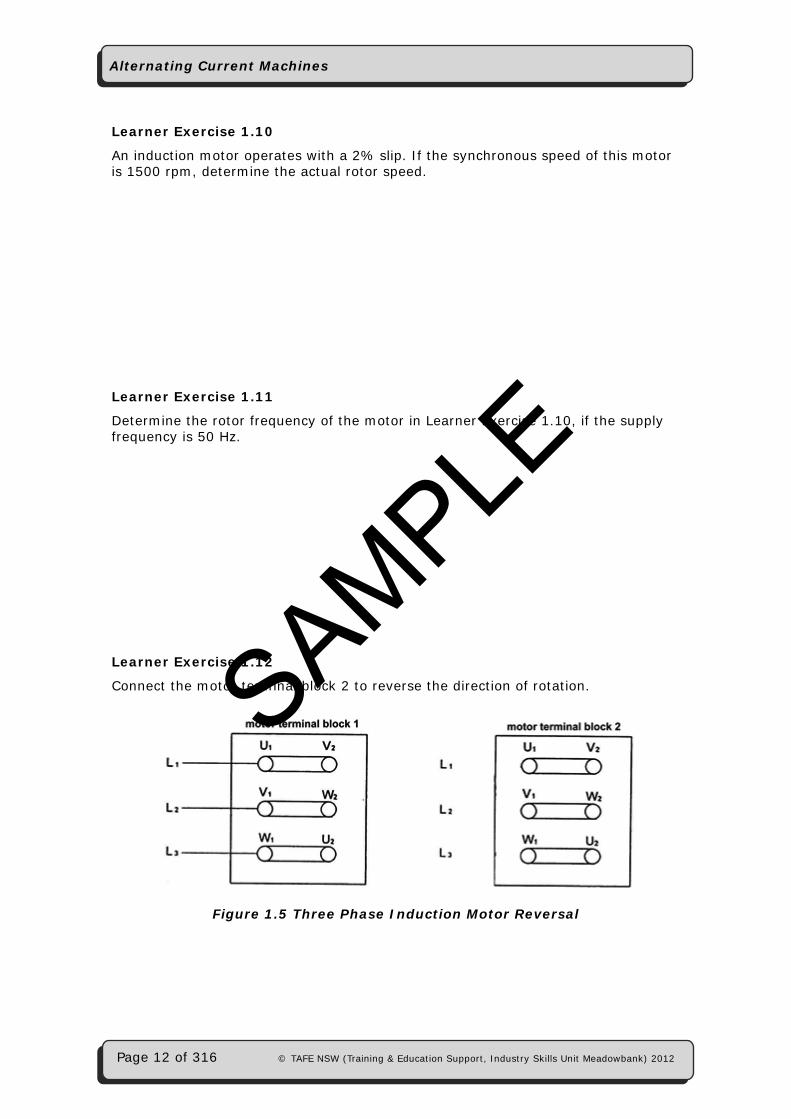
Learner Exercise 1.12
Connect the motor terminal block 2 to reverse the direction of rotation.
Figure 1.5 Three Phase Induction Motor Reversal
SAMPLE
Alternating Current Machines
© TAFE NSW (Training & Education Support, Industry Skills Unit Meadowbank) 2012 Page 13 of 316
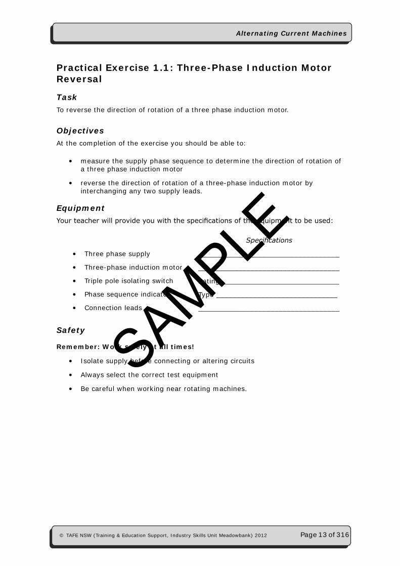
Practical Exercise 1.1: Three-Phase Induction Motor Reversal
TaskTo reverse the direction of rotation of a three phase induction motor.
Objectives At the completion of the exercise you should be able to:
• measure the supply phase sequence to determine the direction of rotation of a three phase induction motor
• reverse the direction of rotation of a three-phase induction motor by interchanging any two supply leads.
EquipmentYourteacherwillprovideyouwiththespecificationsoftheequipmenttobeused:
Specifications
• Three phase supply ___________________________________• Three-phase induction motor ___________________________________• Triple pole isolating switch Rating _____________________________• Phase sequence indicator Type ______________________________• Connection leads ___________________________________
Safety
Remember: Work safely at all times!
• Isolate supply before connecting or altering circuits
• Always select the correct test equipment
• Be careful when working near rotating machines.
SAMPLE

Alternating Current Machines
Page 14 of 316 © TAFE NSW (Training & Education Support, Industry Skills Unit Meadowbank) 2012
Risk Assessment
Identify any hazards, list the supervision level (D, G or B), list the risk class (A, B or C) and list control measures required in the table below:
Hazard Identification
Supervision Level Risk Class Control
Measures
Procedure1. Connect the equipment as shown below leaving line two (L2) disconnected.
Figure 1.6
2. Energise the supply and close the motor isolating switch. Record the effect on the operation of the motor.
Motor rotation = ________________________________.
3. Open the motor isolating switch and isolate the supply. Connect line two to the motor isolating switch.
4. Energise the supply and monitor the phase sequence of the supply with the phase sequence indicator, as shown in the diagram below:
L1
L2
L3
three phaseinductionmotor
motor isolatingswitch
supplyterminal
ACBABC
phasesequenceindicator
Figure 1.7
Record supply phase sequence = ________________________________.
SAMPLE

Alternating Current Machines
© TAFE NSW (Training & Education Support, Industry Skills Unit Meadowbank) 2012 Page 15 of 316
5. Close the motor isolating switch and record the effect on the operation of the motor.
Motor rotation = ________________________________.
6. Open the motor isolating switch and isolate the supply. Interchange the supply connections between lines one and two as shown in the diagram below:
L1
L2
L3
three phaseinductionmotor
motor isolatingswitch
supplyterminal
ACBABC
phasesequenceindicator
Figure 1.8
7. Energise the supply and monitor the phase sequence of the supply with the phase sequence indicator, as shown in the diagram in step 6.
Supply phase sequence = ________________________________.
8. Close the motor isolating switch and note the effect on the operation of the motor.
Motor rotation = ________________________________.
Isolate the supply and return all equipment to its appropriate location.
FeedbackHave your teacher check your results
Teacher Initials/Date
SAMPLE

Alternating Current Machines
Page 16 of 316 © TAFE NSW (Training & Education Support, Industry Skills Unit Meadowbank) 2012
Observations1. Explain the relationship between phase sequence and direction of rotation.
___________________________________________________________
___________________________________________________________
___________________________________________________________
___________________________________________________________
2. What would be the effect on the motor direction of rotation in step 6, if line three (L3) and line one (L1) of the motor were interchanged?
___________________________________________________________
___________________________________________________________
___________________________________________________________
___________________________________________________________
FeedbackHave your teacher check your results
Teacher Initials/Date
SAMPLE
Alternating Current Machines
© TAFE NSW (Training & Education Support, Industry Skills Unit Meadowbank) 2012 Page 17 of 316
Review QuestionsThese questions will help you revise what you have learnt in Section 1.
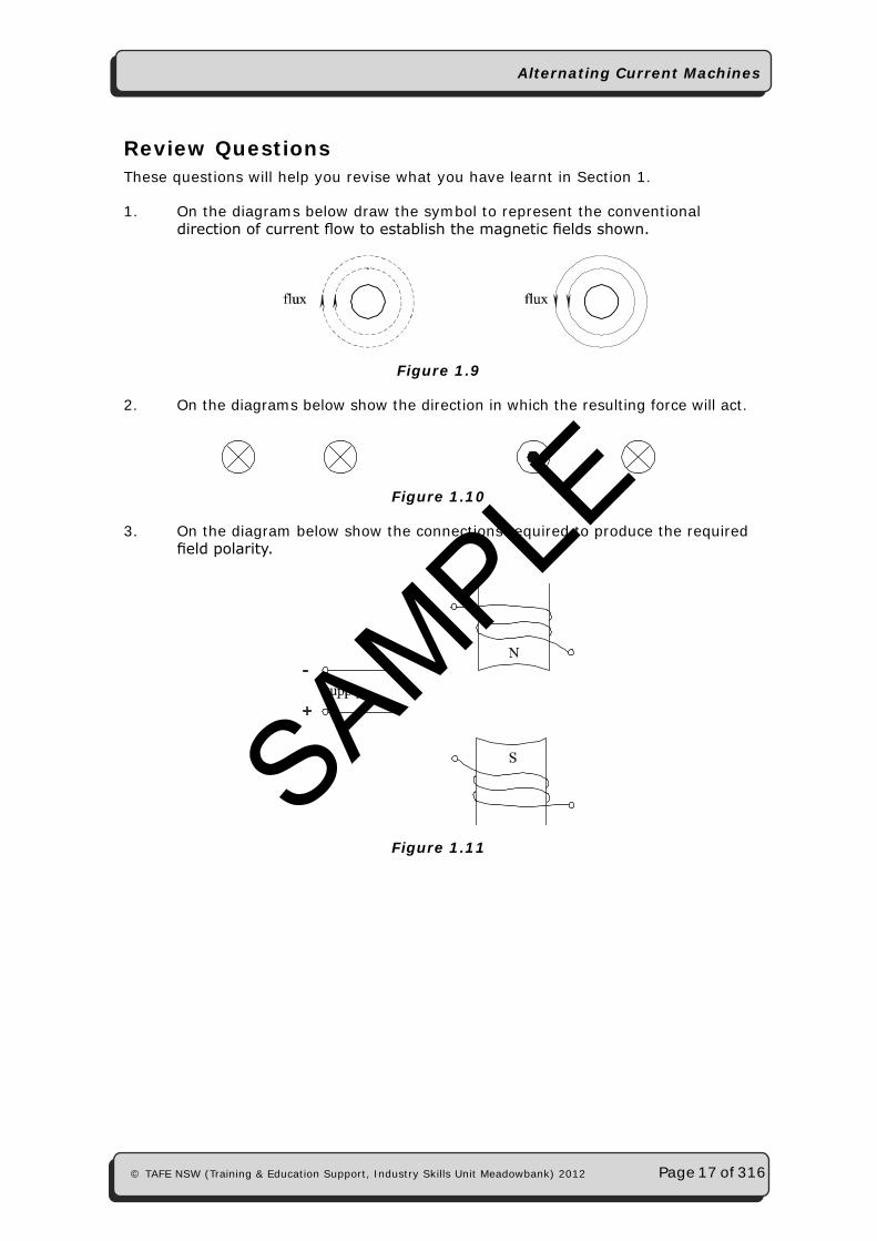
1. On the diagrams below draw the symbol to represent the conventional directionofcurrentflowtoestablishthemagneticfieldsshown.
Figure 1.9
2. On the diagrams below show the direction in which the resulting force will act.
Figure 1.10
3. On the diagram below show the connections required to produce the required fieldpolarity.
Figure 1.11
SAMPLE
Alternating Current Machines
Page 18 of 316 © TAFE NSW (Training & Education Support, Industry Skills Unit Meadowbank) 2012
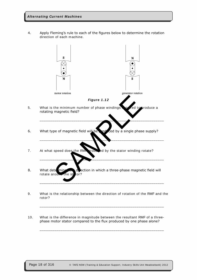
4. ApplyFleming’sruletoeachofthefiguresbelowtodeterminetherotation direction of each machine.
Figure 1.12
5. What is the minimum number of phase windings required to produce a rotatingmagneticfield?
___________________________________________________________
6. Whattypeofmagneticfieldwillbeproducedbyasinglephasesupply?
___________________________________________________________
7. At what speed does the RMF produced by the stator winding rotate?
___________________________________________________________
8. Whatdeterminesthedirectioninwhichathree-phasemagneticfieldwill rotate around the stator?
___________________________________________________________
9. What is the relationship between the direction of rotation of the RMF and the rotor?
___________________________________________________________
10. What is the difference in magnitude between the resultant RMF of a three- phasemotorstatorcomparedtothefluxproducedbyonephasealone?
___________________________________________________________
SAMPLE
Alternating Current Machines
© TAFE NSW (Training & Education Support, Industry Skills Unit Meadowbank) 2012 Page 19 of 316
11. What is developed in the rotor of an induction motor by the interaction of the rotorandstatorfields?
___________________________________________________________
12. Howistherotorfieldofaninductionmotorproduced?
___________________________________________________________
13. What determines the speed of rotation of the RMF produced by a three- phase induction motor?
___________________________________________________________
14. Brieflyexplainwhytherotorspeedofaninductionmotorisalwayslessthan the speed of the stator RMF.
___________________________________________________________
___________________________________________________________
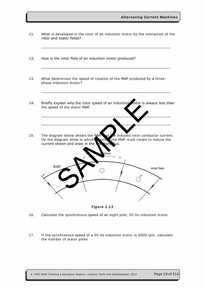
15. The diagram below shows the RMF and the induced rotor conductor current. On the diagram show in which direction the RMF must rotate to induce the currentshownanddrawintheresultantflux.
Figure 1.13
16. Calculate the synchronous speed of an eight pole, 50 Hz induction motor.
17. If the synchronous speed of a 50 Hz induction motor is 3000 rpm, calculate the number of stator poles.
SAMPLE
Alternating Current Machines
Page 20 of 316 © TAFE NSW (Training & Education Support, Industry Skills Unit Meadowbank) 2012
18. Explain the effect of operating a motor designed to operate on 60 Hz if it is connected to a 50 Hz supply.
___________________________________________________________
___________________________________________________________
19. Explainhowarotorfieldisestablishedeventhoughthereisnoelectrical connection between the rotor and the a.c. supply.
___________________________________________________________
___________________________________________________________
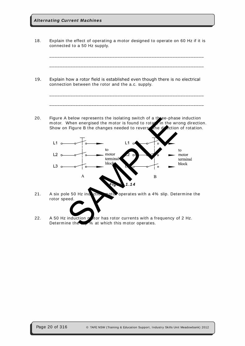
20. Figure A below represents the isolating switch of a three-phase induction motor. When energised the motor is found to rotate in the wrong direction. Show on Figure B the changes needed to reverse the direction of rotation.
Figure 1.14
21. A six pole 50 Hz induction motor operates with a 4% slip. Determine the rotor speed.
22. A 50 Hz induction motor has rotor currents with a frequency of 2 Hz. Determine the slip % at which this motor operates.SAMPLE