leap cell processing workstation user manual · leap workstation main hardware components ......
TRANSCRIPT

LEAP™
Cell Processing Workstation
User Manual
17-LEAP-USER_MANUAL-R07 (PN 0002070-003 on BOM) July 21, 2010
Cyntellect LEAP™ Cell Processing Workstation User Manual
2
Published By Cyntellect®, Inc.
6620 Mesa Ridge Road
San Diego, CA 92121
Direct: 858.875.1600
Toll Free: 877.584.9150
Fax: 858.875.1610
Web Site: www.cyntellect.com
Copyright Copyright © 2010 by Cyntellect. All rights reserved. Cyntellect reserves the right to make modifications and additions to the information in this document without notice. No part of this document may be reproduced or transmitted in any form or means, electronic, photographic, mechanical, or otherwise, for any purpose without the express written permission of Cyntellect.
Trademarks Cyntellect® is a registered trademark, and C-lect™ is a trademark, of Cyntellect. Other products or company names mentioned in this document might be trademarks or registered trademarks of their respective owners, and are treated as such.
Patents The LEAP workstation, software, and portions of this document may be protected by one or more patents and/or pending patent applications, including:
United States: 5,874,266; 6,143,535; 6,514,722; 6,534,308; 6,642,018; 6,753,161; 6,804,385; 7,092,557; 7,129,070; 7,300,795; 7,425,426; 7,505,618; and 7,622,274. Australia: 2002232892; 2002333551; 743239; and 785290. France: 1011697 and 1725653. Germany: 98913223.8 and 1725653. Ireland: 1725653. Netherlands: 1725653. Sweden: 05727754.3. United Kingdom: 1011697 and 1725653.
Appropriate Use
For research and development uses, only. Not for use in diagnostic or therapeutic procedures. The LEAP workstation is designed to perform both user-interactive and automated for the measurement, analysis, and induction of events in cell specimens by imaging cells in microplates, analyzing images, and inducing changes in selected cells via laser irradiation. The LEAP workstation is designed to be used in a temperature and humidity controlled laboratory environment that is free from aerosols, liquid sprays or spills, and excessive airborne dust.
Use of the LEAP™ workstation and software is governed by the LEAP™ Terms and Conditions and the Cyntellect Inc. Software End User License Agreement. For questions, please contact Cyntellect Customer Service at 877.584.9150.
Certifications

Cyntellect LEAP™ Cell Processing Workstation User Manual
3
WARNING: Use this product only in the manner described in this document, and while observing all specified safety precautions. When used other than as specified, the safety features may be impaired or defeated. Failure to adhere to the safety precautions and/or procedures outlined in this document may result in system failure, personal injury, or death, for which Cyntellect shall not be held liable under any circumstances.
WARNING: Risk of electric shock! The LEAP workstation contains voltages and electric currents that are potentially hazardous. To reduce the risk of electric shock, do not remove instrument covers without proper training. Qualified service personnel should perform all repairs.
CAUTION: The LEAP instrument can emit visible and/or invisible Class 3B laser radiation when access doors or exterior panels are open and the safety interlocks are failed or defeated. Avoid eye or skin exposure to direct or scattered radiation. Skin exposure might result in a burn injury. Eye exposure might result in serious injury, possibly including blindness.
CAUTION: The LEAP instrument contains moving mechanical components that are capable of causing bodily harm. Do not reach into the instrument while parts are moving. Keep clothing, jewelry, hair, and other loose materials clear of mechanical components.
Cyntellect LEAP™ Cell Processing Workstation User Manual
4
Contents
Figures ........................................................................................................................................................................... 6
Tables ............................................................................................................................................................................ 7
1. About this Manual ................................................................................................................................................... 9 1.1 Purpose ........................................................................................................................................................ 9 1.2 Summary ...................................................................................................................................................... 9 1.3 Conventions Used in this Manual ............................................................................................................... 10
1.3.1 Hazard Symbols .......................................................................................................................... 10 1.3.2 Other Symbols ............................................................................................................................. 10
1.4 Technical Assistance ................................................................................................................................. 11
2. Safety and Limitations ........................................................................................................................................... 12 2.1 Laser Safety ............................................................................................................................................... 12 2.2 High Intensity Lamp Safety ........................................................................................................................ 13
2.2.1 Intense Light Hazard .................................................................................................................... 13 2.2.2 High Operating Temperature ....................................................................................................... 13
2.3 Electrical Safety ......................................................................................................................................... 14 2.4 Moving Part Hazards .................................................................................................................................. 15
3. LEAP Workstation Overview ................................................................................................................................. 17 3.1 Introduction ................................................................................................................................................ 17 3.2 Hardware Systems ..................................................................................................................................... 18 3.3 Hardware and Optics Subsystems ............................................................................................................. 18 3.4 User Interface and Software ...................................................................................................................... 21
4. LEAP Workstation Operation ................................................................................................................................ 22 4.1 Startup and Shutdown ................................................................................................................................ 22
4.1.1 Startup ......................................................................................................................................... 22 4.1.2 Warm-Up ..................................................................................................................................... 23 4.1.3 Shutdown ..................................................................................................................................... 24
4.2 Operation ................................................................................................................................................... 25 4.2.1 Load a Plate Without Using a Plate Map ..................................................................................... 25 4.2.2 Load a Plate Using a Plate Map .................................................................................................. 27 4.2.3 Plate Navigation and Well Selection ............................................................................................ 29 4.2.4 Saving and Restoring LEAP Configuration States ....................................................................... 31 4.2.5 Machine Control ........................................................................................................................... 33
4.2.5.1 Optical Path Controls ..................................................................................................... 34 4.2.5.2 Beam Expander / Laser Attenuator ................................................................................ 34 4.2.5.3 Laser Centering ............................................................................................................. 34 4.2.5.4 X, Y, Z Position .............................................................................................................. 34 4.2.5.5 Magnification ................................................................................................................. 35
4.2.6 Image Acquisition Settings ........................................................................................................... 36 4.2.6.1 Optical Path ................................................................................................................... 37 4.2.6.2 Camera Settings ............................................................................................................ 38 4.2.6.3 Adjust and Find Optimal Camera Settings ..................................................................... 39 4.2.6.4 Focusing on the Sample ................................................................................................ 40
4.2.6.4.1 Entering an Absolute Position ...................................................................... 41 4.2.6.4.2 Interactive Focusing ..................................................................................... 41 4.2.6.4.3 Automatic Focusing ..................................................................................... 41

Cyntellect LEAP™ Cell Processing Workstation User Manual
5
4.2.7 Image Preprocessing ................................................................................................................... 42 4.2.7.1 Displaying the Image Preprocessing Window ................................................................ 42 4.2.7.2 Well Masking ................................................................................................................. 43 4.2.7.3 Background Correction .................................................................................................. 43 4.2.7.4 Remove Lines ................................................................................................................ 45 4.2.7.5 Conditional Smooth ....................................................................................................... 46 4.2.7.6 Edge Enhancement ....................................................................................................... 46 4.2.7.7 Bright Field Enhancement ............................................................................................. 46
4.2.8 Image Segmentation .................................................................................................................... 47 4.2.8.1 Displaying the Image Segmentation Window ................................................................ 47 4.2.8.2 Method Section .............................................................................................................. 48
4.2.8.2.1 Global Threshold (intensity) ......................................................................... 48 4.2.8.2.2 Local Threshold (intensity) ........................................................................... 49 4.2.8.2.3 Morphology .................................................................................................. 49
4.2.8.3 Preview Segmented Image ............................................................................................ 50 4.2.8.4 Noise Gates Section ...................................................................................................... 50
4.2.8.4.1 Object Size Range ....................................................................................... 50 4.2.8.4.2 Object Elongation Range ............................................................................. 50 4.2.8.4.3 Object Compactness Range ........................................................................ 50
4.2.8.5 Separate Touching Objects ........................................................................................... 50 4.2.8.6 Objects Found ............................................................................................................... 50 4.2.8.7 Auto Update Objects ...................................................................................................... 50 4.2.8.8 Clear Objects ................................................................................................................. 51 4.2.8.9 Find Objects .................................................................................................................. 51 4.2.8.10 Find Objects Report ....................................................................................................... 51
4.2.9 Object Indicator ............................................................................................................................ 52 4.2.10 Focus Map ................................................................................................................................... 52
4.2.10.1 Selecting a Focus Point ................................................................................................. 53 4.2.10.2 Clearing a Focus Point .................................................................................................. 53 4.2.10.3 Deleting all Focus Points ............................................................................................... 53
5. LEAP Workstation Calibration ............................................................................................................................... 54 5.1 Laser Centering .......................................................................................................................................... 54 5.2 Laser Targeting .......................................................................................................................................... 55 5.3 Laser Spot Size Calibration ........................................................................................................................ 55
6. LEAP Workstation Applications ............................................................................................................................ 57 6.1 Introduction ................................................................................................................................................ 57
Appendix A Filter Configuration ................................................................................................. 58
Appendix B Power and Spot Size Data Examples .................................................................... 59
B.1 Green and UV Lasers ................................................................................................................................. 59

Cyntellect LEAP™ Cell Processing Workstation User Manual
6
Figures
Figure 1. LEAP Workstation Main Hardware Components .......................................................................................... 18 Figure 2. 96- and 384-Well Plate Field of Regard Example ......................................................................................... 19 Figure 3. Number of Images Acquired to Image a Single Well ..................................................................................... 20 Figure 4. User Interface ............................................................................................................................................... 21 Figure 5. Power System Warm-Up Status Screen ....................................................................................................... 22 Figure 6. Remove Plate Icon ........................................................................................................................................ 24 Figure 7. Load Plate Icon ............................................................................................................................................. 25 Figure 8. Insert Plate Message .................................................................................................................................... 25 Figure 9. Plate Properties Dialog Box .......................................................................................................................... 26 Figure 10. Plate Calibration Message .......................................................................................................................... 26 Figure 11. Load Plate Map Icon ................................................................................................................................... 27 Figure 12. Insert Plate Message .................................................................................................................................. 27 Figure 13. Load Plate Map Dialog Box ......................................................................................................................... 28 Figure 14. Plate Calibration Message .......................................................................................................................... 28 Figure 15. Plate Tab ..................................................................................................................................................... 29 Figure 16. Well Selection in Plate View Display ........................................................................................................... 30 Figure 17. Channel and Well Position Indicators .......................................................................................................... 31 Figure 18. Load Settings .............................................................................................................................................. 31 Figure 19. Loading and Saving Configuration Settings ................................................................................................ 32 Figure 20. Save Settings .............................................................................................................................................. 32 Figure 21. Machine Control Tab ................................................................................................................................... 33 Figure 22. Optical Path Menu with File Load Window .................................................................................................. 36 Figure 23. Wavelength Menus ..................................................................................................................................... 37 Figure 24. Camera Settings Section ............................................................................................................................ 38 Figure 25. Camera Live ................................................................................................................................................ 39 Figure 26. Exposure Examples .................................................................................................................................... 39 Figure 27. Snap Image ................................................................................................................................................. 40 Figure 28. Focusing on the Sample ............................................................................................................................. 40 Figure 29. Change Position Window ............................................................................................................................ 41 Figure 30. Image Preprocessing Window .................................................................................................................... 42 Figure 31. Background Correction ............................................................................................................................... 43 Figure 32. Image Segmentation Window Showing Local Tab ...................................................................................... 47 Figure 33. Min Grey ..................................................................................................................................................... 48 Figure 34. Local Threshold (intensity) – Changing the Size of the Radius ................................................................... 49 Figure 35. Object (Blob) Report ................................................................................................................................... 51 Figure 36. Object Indicator ........................................................................................................................................... 52 Figure 37. Focus Map .................................................................................................................................................. 53 Figure 38. Laser Energy Measurement vs. Laser Attenuator Position – First Worksheet Example ............................. 59 Figure 39. Laser Energy Measurement vs. Beam Expander Position – Second Worksheet Example ......................... 60 Figure 40. Green Laser Spot Size Calibration Example ............................................................................................... 61 Figure 41. UV Laser Spot Size Calibration Example .................................................................................................... 62
Cyntellect LEAP™ Cell Processing Workstation User Manual
7
Tables
Table 1. Hazard Symbols ............................................................................................................................................. 10 Table 2. Hazard Severities ........................................................................................................................................... 10 Table 3. Additional Symbols ......................................................................................................................................... 10 Table 4. Laser Specifications ....................................................................................................................................... 12 Table 5. LEAP Instrument Warm-Up Periods ............................................................................................................... 23 Table 6. Approximate Pixel Sizes at Each Magnification ............................................................................................. 35 Table 7. Standard Filters on LEAP ............................................................................................................................... 58

Cyntellect LEAP™ Cell Processing Workstation User Manual
8
This page intentionally blank

Cyntellect LEAP™ Cell Processing Workstation User Manual About this Manual
9
1. About this Manual
This chapter provides a brief description of this manual and how to use it.
1.1 Purpose
The purpose of this manual is to describe how to operate the LEAP cell processing workstation, from here on referred to as the LEAP workstation.
1.2 Summary
This manual consists of the following main chapters:
1 – About this Guide – A brief description of this guide and how to use it.
2 – Safety and Limitations – The precautions that you must observe for safe operation of the LEAP workstation.
3 – LEAP Workstation Overview – An overview of the LEAP workstation system and subsystems.
4 – LEAP Workstation Operation – The procedures for operating the LEAP workstation.
5 – LEAP Workstation Calibration – The procedures for calibrating the LEAP workstation.
6 – LEAP Workstation Applications – A brief description of the applications available for use when operating the LEAP workstation.
Appendix A – The list of standard filters used.
Appendix B – Sample power and spot size data.

Cyntellect LEAP™ Cell Processing Workstation User Manual About this Manual
10
1.3 Conventions Used in this Manual
This section describes the symbols and signal words used in this manual. Always read these notations to avoid problems.
1.3.1 Hazard Symbols
This guide uses symbols and associated signal words to communicate safety hazards. The hazard symbols, listed in Table 1, allow for easy and rapid recognition of the hazard type. The signal word definitions, listed in Table 2, comply with the ANSI Z535.4 standard for product safety signs and labels.
Table 1. Hazard Symbols
Symbol Hazard
Voltage or electrical current
Laser light that could cause injury to your eyesight
Moving parts (pinch point hazard)
General
Table 2. Hazard Severities
Signal Word Severity
DANGER Indicates an imminently hazardous situation that could result in severe personal injury or death if it is not avoided.
WARNING Indicates a potentially hazardous situation that could result in severe personal injury or death if it is not avoided.
CAUTION Indicates a potentially hazardous situation that may result in minor or moderate personal injury. It may also alert against unsafe practices. These include practices that may result in workstation damage, data corruption, data loss, or settings loss.
1.3.2 Other Symbols
This guide uses the additional symbols and signal words shown in Table 3.
Table 3. Additional Symbols
Symbol Meaning
A note. Indicates helpful information for the topic or step being described.

Cyntellect LEAP™ Cell Processing Workstation User Manual About this Manual
11
1.4 Technical Assistance
Cyntellect, Inc. Customer Service 6620 Mesa Ridge Road San Diego, CA 92121 Direct: 858.875.1600 Toll Free: 877.584.9150 Fax: 858.875.1610 E-mail: [email protected] Web Site: www.cyntellect.com

Cyntellect LEAP™ Cell Processing Workstation User Manual Safety and Limitations
12
2. Safety and Limitations
This chapter describes the precautions required for safe operation of the LEAP workstation.
Read and understand the safety material in this manual before attempting to use or train on the LEAP workstation. If you are uncertain about any of the safety issues highlighted in this manual or have additional safety concerns, do not hesitate to contact Cyntellect directly with your questions or concerns before attempting to use the LEAP workstation.
2.1 Laser Safety
The LEAP workstation is a Class 1 laser device in normal operation. The LEAP workstation, however, contains two Class 3B lasers that emit at two laser wavelengths. One laser emits invisible ultraviolet (355 nm) radiation while the other emits visible green (532 nm) radiation.
Table 4. Laser Specifications
Specification Laser 1 Laser 2
Wavelength 355 nm 532 nm
Average Power 19.4 mW 27.7 mW
Pulse Width 0.5 nsec 0.5 nsec
In normal operation the laser energy is contained within the instrument by the covers. To ensure safe operation, the covers require tools for removal and are interlocked. However, if the safety interlocks have failed or are defeated, intentionally or otherwise, and the covers removed, it is possible for laser radiation to be emitted outside the instrument. By design, the laser path is contained within the interior frame of the instrument and beam blocks have been strategically located to keep the beam from exiting the instrument even when the front, back and end covers have been removed for servicing. Nonetheless, caution must be exercised and proper safety equipment used any time the instrument covers have been removed.
WARNING! The LEAP instrument can emit visible and/or invisible Class 3B laser radiation when access doors or exterior panels are open and the safety interlocks are failed or defeated. Avoid eye or skin exposure to direct or scattered radiation. Skin exposure might result in a burn injury. Eye exposure might result in serious injury, possibly including blindness

Cyntellect LEAP™ Cell Processing Workstation User Manual Safety and Limitations
13
Therefore, it is mandatory for all persons in the room surrounding the LEAP instrument to wear safety goggles that are rated for filtering Class 3B radiation levels for each of the two wavelengths of laser emission (355 nm and 532 nm) whenever the laser is powered on and any of the following circumstances occur:
The exterior cover is removed from the instrument.
Either of the lasers has been removed from the instrument without disconnecting the power from that laser.
2.2 High Intensity Lamp Safety
The LEAP instrument contains a high-intensity lamp used for the excitation light source. This lamp emits across a broad spectrum of electromagnetic radiation, including ultraviolet, visible, and infrared wavelengths. This lamp is not on the safety-interlocked circuit, so it can continue to operate with the exterior cover removed or the access door open. There are three general hazards associated with this lamp.
2.2.1 Intense Light Hazard
One hazard is that the light emits a very high irradiance level of visible and invisible radiation, which can be damaging to skin and eye tissues when the light is tightly focused onto a small area of tissue. To mitigate this hazard, you must observe the following precautions:
Do not look into the beam of intense light, or into a transmission or reflection of any component of the intense light.
Wear safety goggles for intense light when operating the lamp with the exterior panels removed.
Do not pass your skin into the path of the beam of intense light, or into a transmission or reflection of any component of the intense light.
WARNING! The LEAP instrument’s high-intensity lamp can emit harmful visible and/or invisible electromagnetic radiation when access doors or exterior covers are open. Avoid eye or skin exposure to direct or scattered radiation. Skin exposure might result in a burn injury. Eye exposure might result in serious injury, possibly including blindness.
2.2.2 High Operating Temperature
The second hazard is that the lamp subsystem has a high operating temperature, which: (a) might cause a burn to the skin in the event of direct contact; (b) might ignite materials (such as paper), liquids (such as alcohol or acetone) or vapors (such as from alcohol or acetone) that have a low flashpoint; and, (c) might cause the workstation to overheat if the function of the air-flow cooling system were impeded in any way. To mitigate this hazard, you must observe the following precautions:
When the exterior cover shielding of the high-intensity lamp is removed, be aware that the exposed surfaces can be hot enough to burn your skin.

Cyntellect LEAP™ Cell Processing Workstation User Manual Safety and Limitations
14
Therefore, do not touch any component of the high-intensity lamp subsystem until it has completely cooled to a safe handling temperature.
Do not impede the performance of the lamp‟s cooling system. Keep the workstation‟s exhaust vents and air intake vents free of obstruction.
CAUTION! The LEAP instrument’s high-intensity lamp has a high operating temperature. Exposed surfaces of this lamp and its associated subsystem might be hot enough to cause burns to the skin, and might ignite materials, liquids or gases that have a low flashpoint. Do not touch any component of the high-intensity lamp subsystem until it has completely cooled to a safe handling temperature. Keep flammable liquids and materials away from the lamp subsystem.
2.3 Electrical Safety
The LEAP workstation contains voltages and electric currents that are potentially hazardous. Under normal circumstances, you and other persons in the vicinity of the workstation are protected from accidental contact with these electrical hazards by physical barriers (exterior panels and access doors) and by electrical grounding of the instrument.
To reduce the risk of electric shock:
Do not remove the instrument covers.
Ensure that all three-pronged power cords from the workstation (total of 4) are plugged only into properly grounded receptacles (100 – 220 VAC).
In the event of a spill of an aqueous or other conductive solution within the instrument, power down the system and unplug the power cords before attempting to clean up the spill.
In the event of a foreign object falling into the instrument through an opening (such as the access door or one of the air vents), power down the system and unplug the power cords before attempting to retrieve the foreign object.
Only qualified service personnel should perform repairs on or within the instrument.
WARNING! Risk of electric shock! The LEAP workstation contains voltages and electric currents that are potentially hazardous. To reduce the risk of electric shock, do not remove instrument covers without proper training. Qualified service personnel should perform all repairs.

Cyntellect LEAP™ Cell Processing Workstation User Manual Safety and Limitations
15
2.4 Moving Part Hazards
The LEAP instrument contains mechanical components that move. Some of these components move in a linear fashion (for example, the x-axis and y-axis movements of the specimen stage), and some of these components have a rotational motion (for example, the galvanometer motors and the filter wheels).
The LEAP instrument‟s moving components can pose risks of pinching, crushing, cutting, twisting or entrapping body parts, particularly hands and fingers. To avoid injury by the instrument‟s moving components, you must observe the following precautions.
While an application is executing, keep the access door in the closed position.
While an application is executing, the various mechanical components of the LEAP instrument can move at any time, without warning. Do not reach into the instrument while an application is executing, unless the application specifically requests that a new specimen plate be loaded onto the stage, at a particular time.
Do not reach into the instrument to remove or load a specimen plate while the stage is still moving. Wait until the stage has come to a complete stop, before reaching into the instrument.
Keep clothing, jewelry, hair, and other loose materials clear of the instrument‟s mechanical components while applications are executing or components are moving. Components can move at any time and can catch hold of loose materials, forcing a body part into a dangerous position.
CAUTION: The LEAP instrument contains moving mechanical components that are capable of causing bodily harm. Do not reach into the instrument while parts are moving. Keep clothing, jewelry, hair, and other loose materials clear of mechanical components.

Cyntellect LEAP™ Cell Processing Workstation User Manual Safety and Limitations
16
This page intentionally blank

Cyntellect LEAP™ Cell Processing Workstation User Manual LEAP Workstation Overview
17
3. LEAP Workstation Overview
This chapter provides an overview of the LEAP workstation and subsystems.
3.1 Introduction
The LEAP workstation is a microplate-based cytometry system for in situ cellular analysis and purification. The LEAP workstation combines high-speed whole well imaging and ultra fast laser manipulation for selective and efficient processing of cells in their natural state. This non-invasive in situ process allows various adherent and non-adherent cell types including primary cells, cancer cells, and stem cells to be purified in a closed sterile microplate environment with very high yield in less than half the time compared to other conventional techniques. LEAP applications include in situ purification of various cell types, rapid cell line development and stem cell processing and generation.
The LEAP workstation maximizes utility with the following array of capabilities:
Employs ultra-fast laser optics for selective and efficient processing of cells
Provides data from all cell types, adherent and non-adherent
Allows brightfield cell imaging, identification, and characterization
Enables fluorescence imaging and identification
Analyzes every cell in every well due to elimination of brightfield edge effect
Rapidly images the entire well (up to 40 times faster than typical imaging systems)
Requires minimal sample manipulation
Operates on a variety of multi-well plate formats
Ultra high-throughput processing on the LEAP workstation is achieved by using a large field-of-regard (FOR) F-theta lens with high-speed galvanometer mirrors that scan a large surface area. These scanning mirrors can obtain a series of images (“fields-of-view” or FOV) as well as steer the laser beam to hit target cells. The use of automated and robust components from the semiconductor manufacturing industry in LEAP provides a level of technological sophistication that is unique in the life sciences arena.

Cyntellect LEAP™ Cell Processing Workstation User Manual LEAP Workstation Overview
18
3.2 Hardware Systems
Looking at the LEAP components from their highest viewpoint level, the LEAP “workstation” consists of four main hardware components, as shown in Figure 1.
LEAP instrument
Personal Computer (PC)
PC monitor
Keyboard and mouse
Figure 1. LEAP Workstation Main Hardware Components
When referring to the LEAP system as a whole, the term “LEAP workstation” is used. When referring to only the instrument portion of the LEAP system, the term “LEAP instrument” is used.
3.3 Hardware and Optics Subsystems
The LEAP instrument contains several hardware and optical subsystems:
Multi-color fluorescence excitation and imaging optics (three 8-position filter wheels, for excitation filters, dichroic filters, and emission filters)
LED-based brightfield illumination
Image magnifier (3X, 5X, 10X, and 20X)
Intensified mega-pixel CCD camera
Rapid auto-focus
Lasers and laser beam delivery optics (with spot size and intensity controls)
F-theta lens, which defines the Field of Regard (FOR), with scanning galvanometer mirrors
x/y/z stage system for plate loading and accurate positioning
LEAP Workstation
Keyboard
Monitor
PC
LEAP Instrument

Cyntellect LEAP™ Cell Processing Workstation User Manual LEAP Workstation Overview
19
The LEAP workstation possesses a unique optical system that enables it to image and manipulate cells at unprecedented speeds. The large FOR lens views a significantly larger area than conventional microscope imaging systems.
Figure 2 shows the following LEAP FOR examples:
(A) The FOR covers 4 wells of a 384-well plate.
(B) The FOR covers 1 well of a 96-well plate.
The red circle shows the area that the lens views (the “FOR”) for each of the two plate types.
Figure 2. 96- and 384-Well Plate Field of Regard Example
96-Well Plate FOR 384-Well Plate FOR

Cyntellect LEAP™ Cell Processing Workstation User Manual LEAP Workstation Overview
20
As shown in Figure 3, multiple images (squares) are acquired within the optical field in order to provide the ability to image the entire well (circle). A physical stage movement and focus occurs only when moving the optical view from well to well.
Figure 3. Number of Images Acquired to Image a Single Well
Magnification 384-Well Plate 96-Well Plate
3X
1 image - 384-well
16 images - 96-well
5X
4 images - 384-well
32 images - 96-well
10X
16 images - 384-well
120 images - 96 - well
20X
45 images - 384-well
408 images - 96-well

Cyntellect LEAP™ Cell Processing Workstation User Manual LEAP Workstation Overview
21
3.4 User Interface and Software
The software interface is designed around the workflow that you need to execute. The optical components are controlled through the graphical user interface, allowing easy visualization and changing of instrument settings by simply clicking on each component in the interface diagram.
The LEAP workstation is organized in two screens on separate monitors (Figure 4). The left side of the left screen provides the workflow as a series of collapsible menus that start from loading a sample into the system to viewing the results. The right-hand screen generally contains the imaging controls.
The three main tabs on the right-hand monitor are:
Image Preprocessing – For selecting the types of corrections and enhancements you want the system to make when capturing images.
Image Segmentation – For making selections that will allow the system to locate objects, typically cells, separating them from the background into individual entities.
Optical Path – For selecting the required illumination source, filter settings, camera settings, and focusing capabilities.
CAUTION! The LEAP workstation computer should not be used for applications other than those provided with the LEAP workstation. Doing so may cause damage to the hardware or system settings, leaving the instrument in a compromised or totally inoperable state that can only be corrected by trained service personnel.
Figure 4. User Interface
Workflow Configuration Settings
Tabs

Cyntellect LEAP™ Cell Processing Workstation User Manual LEAP Workstation Operation
22
4. LEAP Workstation Operation
The following are the procedures for operating the LEAP workstation (instrument and computer).
4.1 Startup and Shutdown
This section describes the procedures for starting up and shutting down the LEAP workstation (instrument and computer).
4.1.1 Startup
Perform the following steps to start up the LEAP workstation (instrument and computer).
1. Turn on the LEAP instrument by switching on the main power button.
2. Turn on the LEAP computer.
3. Log in to the LEAP application computer.
The default User Name and Password, in both fields, are leap. User Name
and Password can be reset by the user Remember that passwords are case sensitive.
4. Launch the LEAP application using the “LEAP” icon, located on the desktop.
The program opens and the initial startup screen, called Power System Warm-Up Status (Figure 5), appears on the left-hand monitor.
The laser and camera turn on automatically; therefore the radio boxes for Laser and Camera are greyed out.
Figure 5. Power System Warm-Up Status Screen
NOTE: The Power System Warm-Up Status will differ for LEAP instruments with an environmental chamber. For information on the environmental chamber, see 17-LEAP-USER_MAN_SUPPL-ENV.

Cyntellect LEAP™ Cell Processing Workstation User Manual LEAP Workstation Operation
23
5. If you are going to use the Excitation Lamp during instrument operation, select the Excitation Lamp checkbox (Figure 5) to turn the lamp on.
When you check the checkbox, a cooling fan becomes audible.
You may uncheck the checkbox to turn off the lamp between procedures if you are not going to shut down the instrument.
4.1.2 Warm-Up
Use the LEAP instrument warm-up periods listed in Table 5, according to the listed components to be used. The warm-up periods, communicated in the Initial Startup Screen (Figure 5), allow for optimal subsystem performance.
Table 5. LEAP Instrument Warm-Up Periods
Component LEAP Instrument Warm-Up Period
Laser 10 minutes
Exception: If you will be using the laser for laser centering or targeting (sections 5.1 or 5.2), a 45-minute instrument warm-up period is recommended for optimal accuracy.
Excitation lamp 5 minutes
Camera 10 minutes
The current version of the LEAP application does not provide a safeguard against premature use of these subsystems; therefore, it is the user‟s responsibility to ensure that the appropriate warm-up period has elapsed before using these subsystems.
Cyntellect LEAP™ Cell Processing Workstation User Manual LEAP Workstation Operation
24
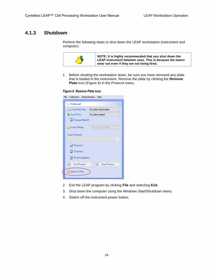
4.1.3 Shutdown
Perform the following steps to shut down the LEAP workstation (instrument and computer).
NOTE: It is highly recommended that you shut down the LEAP instrument between uses. This is because the lasers wear out even if they are not being fired.
1. Before shutting the workstation down, be sure you have removed any plate that is loaded in the instrument. Remove the plate by clicking the Remove Plate icon (Figure 6) in the Protocol menu.
Figure 6. Remove Plate Icon
2. Exit the LEAP program by clicking File and selecting Exit.
3. Shut down the computer using the Windows Start/Shutdown menu.
4. Switch off the instrument power button.

Cyntellect LEAP™ Cell Processing Workstation User Manual LEAP Workstation Operation
25
4.2 Operation
Begin LEAP instrument operation by doing either of the following:
Load a plate without using a plate map
Load a plate using a plate map
A plate map contains user-defined parameters created using the Plate Map Editor). Once a plate map is loaded, the processing is fully automated.
4.2.1 Load a Plate Without Using a Plate Map
1. Click the Load Plate icon in the Protocol menu.
Figure 7. Load Plate Icon
The sliding access door on the top panel opens and the Insert Plate message appears.
Figure 8. Insert Plate Message
CAUTION: Do not reach into the instrument while the stage is in motion!
The LEAP instrument contains moving mechanical components that are capable of causing bodily harm. Do not reach into the instrument while parts are moving. Keep clothing, jewelry, hair, and other loose materials clear of mechanical components.
2. Place the plate carefully in the plate carrier through the sliding access door on the top panel, making sure of the following:
Make sure that the well labeled “A1” is in the upper left corner of the plate carrier.
Make sure that the plate is fully seated flat in the stage before attempting to process the plate. If the plate is not seated securely in its proper position, the instrument will be unable to reliably focus on the entire plate.

Cyntellect LEAP™ Cell Processing Workstation User Manual LEAP Workstation Operation
26
3. In the Insert Plate message, click OK.
The access door closes and a Plate Properties window appears (Figure 9).
Figure 9. Plate Properties Dialog Box
4. In the Plate Properties dialog box, select the following to describe the plate you placed into the instrument:
a. In Label, select the Plate ID.
b. In Plate Type, select the type of plate.
NOTE: If the LEAP workstation is equipped with a barcode scanner, the system automatically selects the Plate Type, the selection can not be modified, and the barcode number appears at the bottom of the Plate Properties window.
5. Click OK.
NOTE: On some units, depending on the user-requested configuration, a “Please choose the type of calibration” message appears. Select Manual, Automatic, or Cancel, as appropriate. Selecting Manual will result in interactive windows throughout calibration; Automatic will calibrate without user interaction.
A Plate Calibration message appears (Figure 10) and an automated calibration starts that adapts to the geometry of the selected plate.
Figure 10. Plate Calibration Message

Cyntellect LEAP™ Cell Processing Workstation User Manual LEAP Workstation Operation
27
4.2.2 Load a Plate Using a Plate Map
1. Click the Load Plate Map icon (Figure 11) in the Protocol menu.
Figure 11. Load Plate Map Icon
The sliding access door on the top panel opens and the Insert Plate message appears.
Figure 12. Insert Plate Message
CAUTION: Do not reach into the instrument while the stage is in motion!
The LEAP instrument contains moving mechanical components that are capable of causing bodily harm. Do not reach into the instrument while parts are moving. Keep clothing, jewelry, hair, and other loose materials clear of mechanical components.
2. Place the plate carefully in the plate carrier, making sure of the following:
Make sure that the well labeled “A1” is in the upper left corner of the plate carrier.
Make sure that the plate is fully seated flat in the stage before attempting to process the plate. If the plate is not seated securely in its proper position, the instrument will be unable to reliably focus on the entire plate.
3. In the Insert Plate message, click OK.

Cyntellect LEAP™ Cell Processing Workstation User Manual LEAP Workstation Operation
28
The access door closes and a Load Plate Map dialog box appears (Figure 9).
Figure 13. Load Plate Map Dialog Box
4. In the Load Plate Map dialog box, select the following to describe the plate you placed into the instrument:
a. In Plate Map, locate the previously made plate map file by clicking the . . . button.
b. In Plate ID, select the Plate ID.
c. In Plate Type, select the type of plate.
NOTE: If the LEAP workstation is equipped with a barcode scanner, the system automatically selects the Plate Type, the selection can not be modified, and the barcode number appears at the bottom of the Load Plate Map dialog box.
5. After a plate map is loaded, select where to save the data by clicking Set Results Path.
6. Click OK.
NOTE: On some units, depending on the user-requested configuration, a “Please choose the type of calibration” message appears. Select Manual, Automatic, or Cancel, as appropriate. Selecting Manual will result in interactive windows throughout calibration; Automatic will calibrate without user interaction.
A Plate Calibration message appears (Figure 14), and an automated calibration starts that adapts to the geometry of the selected plate.
Figure 14. Plate Calibration Message

Cyntellect LEAP™ Cell Processing Workstation User Manual LEAP Workstation Operation
29
4.2.3 Plate Navigation and Well Selection
Navigate from well to well as follows:
In the Plate tab (Figure 15), click the appropriate well.
Figure 15. Plate Tab
C-lect 96-well Plate C-lect Calibration Mirror
Blue box indicates the position of the stage over the theta lens Calibration mirror is used for laser centering, laser targeting, and laser spot size wizards
After loading a plate, click any well in the plate view display to move to that well.
Zoom in on the plate view display as needed by selecting the plate view display and using the mouse scroll wheel.
The blue box appears over the selected position.
Navigate to wells or select them for processing by doing either of the following two methods:
Anywhere in the plate view display, right-click and select Well Navigation or Well Selection
Click the Well Selection/Well Navigation button below the plate view display (Figure 16).
NOTE: You can select rows, columns, rectangular regions, or the whole plate using logical spreadsheet-type selection methods (Figure 16).

Cyntellect LEAP™ Cell Processing Workstation User Manual LEAP Workstation Operation
30
Figure 16. Well Selection in Plate View Display
Selecting more than one well allows the application to process all wells within the selection.
NOTE: When loading a plate using a Plate Map , all wells are automatically selected for processing.
Column
Whole Plate
Row
Rectangular Selection

Cyntellect LEAP™ Cell Processing Workstation User Manual LEAP Workstation Operation
31
During processing, colored squares appear to indicate the channel and well position being imaged. The selected protocol determines the colors. In the example shown in Figure 17, red and green indicators show the progress of the two channels being imaged.
Figure 17. Channel and Well Position Indicators
4.2.4 Saving and Restoring LEAP Configuration States
Configuration conditions including Protocol, Optical Path, Image Pre-processing, and Image Segmentation can be saved and recovered from a single file.
After loading a plate, it is possible to load a prior set of configuration conditions using the Load Settings icon (Figure 18) in the Protocol menu.
Figure 18. Load Settings
Red Channel Processing
Green Channel Processing

Cyntellect LEAP™ Cell Processing Workstation User Manual LEAP Workstation Operation
32
After a set of conditions is established that will be either routine or provide a good starting point for processing, you can save it for rapid re-use.
To save settings for re-use
Select File > Save Settings As (Figure 19).
Figure 19. Loading and Saving Configuration Settings
The Save settings dialog box appears (Figure 20).
Figure 20. Save Settings
Cyntellect LEAP™ Cell Processing Workstation User Manual LEAP Workstation Operation
33
All configuration settings are also saved with the data from an experiment. It is possible to use settings from a prior experiment by importing the configuration settings file from the data directory of that experiment using the File menu (Figure 19). From Import Settings from Results Folder… a dialog box will allow selection of the appropriate file.
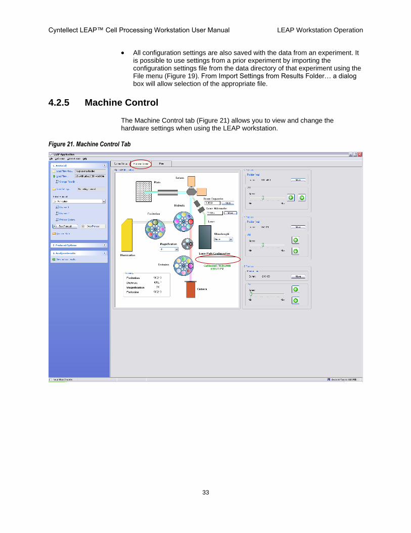
4.2.5 Machine Control
The Machine Control tab (Figure 21) allows you to view and change the hardware settings when using the LEAP workstation.
Figure 21. Machine Control Tab

Cyntellect LEAP™ Cell Processing Workstation User Manual LEAP Workstation Operation
34
4.2.5.1 Optical Path Controls
A schematic representation of the system hardware contains interactive menus that allow you to control some of the current hardware settings of the system. A summary of the settings you are currently using is displayed on the bottom left of the diagram. A popup with the filter wavelength or magnification setting will appear as you move the mouse over the filter diagram.
Settings for the laser wavelength, laser attenuator and beam expander can be saved and loaded. If loaded, the name of the file will appear in the Laser Path Configuration field (Figure 21).
4.2.5.2 Beam Expander / Laser Attenuator
This is the menu for settings controlling the operation of the laser, including selecting which laser to use (UV (355 nm) or Green (532 nm)), varying the energy of the laser pulse (Laser Attenuator) and the position of the focus of the laser (Beam Expander).
The Beam Expander adjusts the focus of the laser. In some cases, the goal is to hit the cell with a focused beam (B.E. position that creates the smallest spot size). In other cases, the goal is to hit the cell with a de-focused beam (B.E. position that creates a larger spot size, which is less (in mm) than the position that created the smallest spot size). See Appendix B for Beam Expander position (mm) vs. spot size radius (µ).
The Laser Attenuator adjusts the amount of energy that is transmitted from the laser to the sample.
4.2.5.3 Laser Centering
Before proceeding to X, Y, Z Position, perform laser centering and targeting per sections 5.1 and 5.2, respectively.
4.2.5.4 X, Y, Z Position
The X, Y, Z motors are the motors that control the movement of the stage/plate in relation to the F-theta lens. They are useful for manual scanning around a plate or inside a well.
The X Position will shift the well along the x axis. The Y Position will shift the well along the y axis. The Z Position will shift the cell into and out of focus.
Absolute position can be entered via the "Move" buttons which will pop up for entering the position.
The arrow buttons will move the object (well or cells) in the direction of the arrow. The slider controls the velocity of the movement.

Cyntellect LEAP™ Cell Processing Workstation User Manual LEAP Workstation Operation
35
4.2.5.5 Magnification
The magnification wheel contains options for 3x, 5x, 10x, and 20x viewing. At 3x magnification, an entire 384 well plate sized well is visible in one FOV. Table 6 lists the approximate pixel sizes at each magnification. The exact pixel size at each magnification will differ for each LEAP instrument.
Table 6. Approximate Pixel Sizes at Each Magnification
Magnification Approximate Pixel Size
3X 2.0 µm
5X 1.2 µm
10X 0.6 µm
20X 0.3 µm

Cyntellect LEAP™ Cell Processing Workstation User Manual LEAP Workstation Operation
36
4.2.6 Image Acquisition Settings
1. On the right-hand monitor, select the tab for the image channel (Figure 22 item A) that you want to set up on the right-hand monitor.
Figure 22. Optical Path Menu with File Load Window
2. Click the Optical Path tab (Figure 22 item B).
3. All conditions set from this menu can be saved into a file and later retrieved (Figure 22 item C). If you have prior settings to restore, select the Load button and select the file. After you have made changes, select the Save As button to save those settings with a descriptive name.
B Optical Path Tab
Channel Tabs A
C File Load Window (Channel Manger)

Cyntellect LEAP™ Cell Processing Workstation User Manual LEAP Workstation Operation
37
4.2.6.1 Optical Path
Do the following in the LEAP Image Display window‟s Optical Path window.
Set up the filter combinations for the imaging conditions (e.g. fluorescence with a particular set of filters or brightfield) for that image channel.
Appendix A Table 7 provides a recommended list of available filter combinations for particular dyes. Any combination of filters can be selected, and it is encouraged that you verify that the combination of filters provides the appropriate image.
Current filter settings are displayed. You can use the drop-down menus to change the Illumination Source and Excitation, Emission and Dichroic filters (Figure 23).
Figure 23. Wavelength Menus
Illumination Source can be either Brightfield or Fluorescence.
Brightfield and fluorescence are both white-light illumination.
Both brightfield and fluorescence use dichroic and emission filters; Fluorescence additionally uses an excitation filter.

Cyntellect LEAP™ Cell Processing Workstation User Manual LEAP Workstation Operation
38
4.2.6.2 Camera Settings
Select camera settings in the Camera Settings section (Figure 24) of the Optical Path menu as follows.
Figure 24. Camera Settings Section
Frame Exposure Time (ms)
The slide bar controls the length of time over which the camera integrates the signal to define a frame. Thus, in Figure 24, a “frame” is defined as an exposure of 151.26 ms. If for example, the “Number of Frames to Average” is set to 2, then 2 frames of 151.26 ms each are averaged together to achieve the Total Capture Time (ms) of 302.52. The default (and recommended) Frame Exposure Time (ms) is 32. Clicking the Reset Exposure will reset the Frame Exposure Time (ms) to the default of 32 ms.
Gain (volts)
The camera includes an electron multiplying (EM) register at the end of the serial register. The gain setting controls the amount of ion impact amplification within this register which allows the viewing of extremely low light level images, such as from fluorescently labeled cells.
Number of Frames to Average (1-8)
Frame averaging is used to minimize camera noise that may be due to a high gain value.
“Number of Frames to Average” determines the number of frames that are averaged together to provide the final image. Frame averaging will improve the signal-to-noise ratio of the images by decreasing the random noise. The image of the cells should improve with the averaging of larger numbers of frames. The trade-off for a better image is the greater amounts of time necessary to acquire large numbers of frames.
Binning (1, 2 or 4)
This feature will reduce resolution but increase sensitivity and speed. Default setting is 1, which will not change the image.

Cyntellect LEAP™ Cell Processing Workstation User Manual LEAP Workstation Operation
39
When set to 2, the software will add the intensity of a 2x2 pixel area and put it into 1 pixel, and then stretch the image back to the original size. Therefore a 1000x1000 pixel image will still be a 1000x1000 pixel image, but each 2x2 pixel square will have the same value, resulting in a 500x500 resolution
When set to 4, the software will use a 4x4 pixel area instead of a 2x2 pixel area.
4.2.6.3 Adjust and Find Optimal Camera Settings
1. Select the Camera Live button (Figure 25, circled item), located on the top of the right hand monitor, to see a live, real-time image.
Figure 25. Camera Live
2. To minimize camera noise, adjust first the Frame Exposure Time between 0 to 32 ms, keeping the Gain slider at 0. If the signal is still not visible at 32 ms, increase the Gain until the signal is visible or the camera noise becomes apparent. If the signal is still not visible, then increase the Frame Exposure Time until the signal is visible.
3. Slide the Exposure and Gain settings until you can see all of the cells in the image. Then minimize the Exposure and Gain settings so that you can still see all the cells without overexposing the image (Figure 26). The best exposure and gain settings allow imaging of both the brightest and the dimmest objects simultaneously.
Figure 26. Exposure Examples
Good Exposure Over-Exposure Under-Exposure
4. If no cells are visible, they may be out of focus. Use the focus panel and adjust focus if necessary (see next section).

Cyntellect LEAP™ Cell Processing Workstation User Manual LEAP Workstation Operation
40
5. Select the Snap Image button (Figure 27, circled item) to take a picture and turn off the live camera. You may also snap an image, without using the live video, to help prevent photo bleaching of a fluorescent sample because the sample is being exposed to excitation light for the duration needed to take a picture (Total Capture Time [ms]).
Figure 27. Snap Image
4.2.6.4 Focusing on the Sample
You focus on the sample (Figure 28) by moving the Z Position (sample carrier), using any of the following methods:
Focus on the sample using any of the following methods:
Enter a value for an absolute position
Interactively move in increments according to your observation
Allow the system to automatically judge the focus by its finding the image with the maximum contrast (that is, the image with the sharpest edges)
Figure 28. Focusing on the Sample
A
B
C

Cyntellect LEAP™ Cell Processing Workstation User Manual LEAP Workstation Operation
41
4.2.6.4.1 Entering an Absolute Position
1. In the Z Position section‟s Position section, click the Move button (Figure 28 item A).
A Change Position window (Figure 29) appears.
Figure 29. Change Position Window
2. In the Change Position window‟s Position field, type or select the value you want and then click OK.
Moving the Z Position in a negative direction moves the sample downward, closer to the lens
Moving the Z Position in a positive direction moves the sample upward, away from the lens
4.2.6.4.2 Interactive Focusing
In the Z Position section‟s Jog section, click the Up and Down arrow buttons (Figure 28 item B in section 4.2.6.4) to move the stage.
Move the slider bar to the left of the Up and Down buttons to control how far each Up or Down click will move the stage.
Min – Moves the sample the slowest.
Max – Moves the sample the fastest.
4.2.6.4.3 Automatic Focusing
In the Focus section, click the Refocus or Auto Focus button (Figure 28 item C in section 4.2.6.4) to tell the instrument to find the ideal focus for the sample, based on the image with the maximum contrast (that is, the image with the sharpest edges).
The differences between the two buttons are as follows:
The range scanned (on the Z axis) is larger for the Auto Focus than the Refocus.
Refocus works in 1 µm increments.
Auto Focus works in 10 µm increments.
Click one of the following:
Refocus – Click if the sample is only slightly out of focus
Auto Focus – Click if the sample is greatly out of focus

Cyntellect LEAP™ Cell Processing Workstation User Manual LEAP Workstation Operation
42
4.2.7 Image Preprocessing
Preprocessing options allow you to perform image processing before the data is analyzed. The preprocessing options must be selected independently for each fluorescence channel.
4.2.7.1 Displaying the Image Preprocessing Window
On the right-hand monitor, click the Image Preprocessing tab.
The Image Preprocessing window appears (Figure 30).
Figure 30. Image Preprocessing Window
3. To apply a feature, click a checkbox to the left of the feature (Figure 30 circled items).
For a description of each setting, see sections 4.2.7.2 through 4.2.7.7.
Cyntellect LEAP™ Cell Processing Workstation User Manual LEAP Workstation Operation
43
4.2.7.2 Well Masking
The well masking operations delineate the working area of the image by masking any regions that fall outside the well. With the Mask Well operation selected, all subsequent processing is calculated and performed within the masked region (e.g., background correction) including object finding.
The following are the well masking selections:
Mask Well: Execute well masking operations.
Search (%): Percent of area from the center to evaluate for masking well.
Adjust (Pixels): Number of pixels to expand or shrink well mask.
Attempt to Find Well Mask: This setting attempts to match the well mask to the well.
To view the well mask outline, select the Well Mask option from the Overlay pulldown menu (Figure 36 in section 4.2.9).
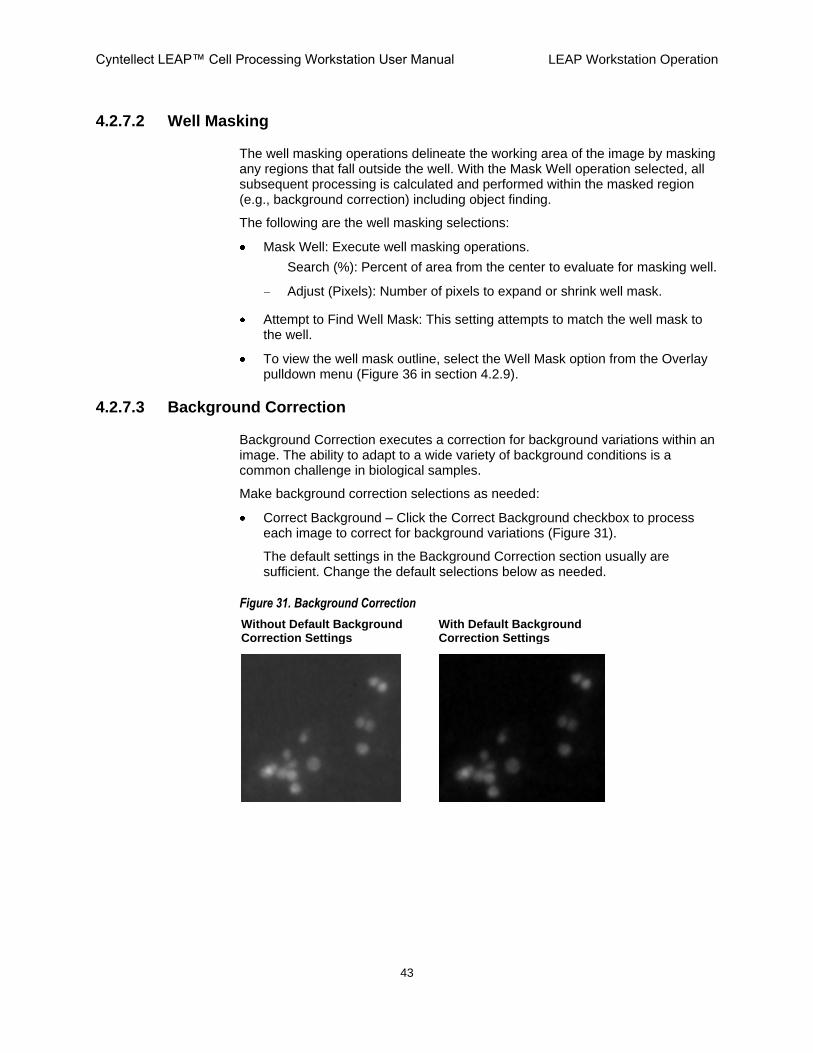
4.2.7.3 Background Correction
Background Correction executes a correction for background variations within an image. The ability to adapt to a wide variety of background conditions is a common challenge in biological samples.
Make background correction selections as needed:
Correct Background – Click the Correct Background checkbox to process each image to correct for background variations (Figure 31).
The default settings in the Background Correction section usually are sufficient. Change the default selections below as needed.
Figure 31. Background Correction
Without Default Background Correction Settings
With Default Background Correction Settings
Cyntellect LEAP™ Cell Processing Workstation User Manual LEAP Workstation Operation
44
Additive – Algorithm samples the image over a grid of sampling regions establishing a value based on the Point Method chosen. For example, if Minimum is chosen, then the minimum of the sample region is recorded. After processing all sample regions, a surface is fit to the data creating the „background‟ image for subtracting from the image. These sampled points may represent either true background or actual object values. The „Trim Outliers‟ value is used to trim the higher pixel values from the distribution. The Visible Background and Coverage parameters determine the sampling grid and area of image covered.
Additive Options section
Point Method (Minimum / Average / Maximum) – Calculation performed within a region of the sample grid.
o Minimum – Minimum of the pixels
o Average – Average of the pixels
o Maximum – Maximum of the pixels
Trim Outliers – Using a histogram of the values for each sampling region, it is possible to remove outlying object intensities from the background intensities.
StdDevs – Standard deviation about the mean of the values to trim from the distribution.
Additive & Multiplicative – Use both the Additive correction (background subtraction) as well as a Multiplicative algorithm. The Multiplicative algorithm corrects for non-uniform illumination across an image. The algorithm samples the image over a grid of sampling regions establishing a value based on the Point Method chosen. For example, if Average is chosen, then the average of the sample region is recorded. After processing all sample regions, a surface is fit to the data creating the multiplicative correction image for multiplying with the image. The „Trim Outliers‟ value is used to trim the extreme pixel values from the distribution. The „Visible Background‟ and „Coverage‟ parameters determine the sampling grid and area of image covered.
Multiplicative Options section
Point Method – (Minimum / Average / Maximum – Calculation performed within a region of the sample grid.
Trim Outliers – Using a histogram of the values for each sampling region, it is possible to remove outlying object intensities from the background intensities
StdDevs – Standard deviation about the mean of the values to trim from the distribution.
Fit Precision – Defines the overall precision of the surface that is fit to the data. Too low of a precision can lead to inadequate compensation for the variances within the image.

Cyntellect LEAP™ Cell Processing Workstation User Manual LEAP Workstation Operation
45
Visible Background (Normal / Low) – In general, this variable determines the number of points the software will look at to determine the background correction. The selection of this variable is based on how much area in the well is a non-signal.
Normal – Select when imaging lower density cultures and the area of visible background is medium to high. Uses a 10 x 10 grid. Normal is recommended.
Low – Select when imaging high density cultures and the area of visible background is minimal. Uses a 20 x 20 grid.
Coverage (%): Percent area of image from the center over which to place the sampling grid.
Suppress Tails Outside of Mask: Option is used in conjunction with well masking. When background correction is applied to a masked area it is possible the regions outside the mask will have wildly random patterns. This option sets all values outside the mask to zero.
4.2.7.4 Remove Lines
Remove Lines removes all lines, including really short ones – the ones that look like cells. These lines are usually the result of scratches or stray fiber-type objects that can complicate interpretation of the image.
Make Remove Lines selections as needed:
Remove
Applies the remove line filter when checked.
Horizontal
Removes linear objects that are mainly horizontal.
Vertical
Removes linear objects that are mainly vertical.
Both
Removes linear objects that fall both along the vertical and the horizontal directions.
Variance
Removes linear objects that are not 100% vertical or horizontal. You determine the width of the lines to filter.
Cutoff
Cutoff is an option to keep short lines in the image. The Cutoff number is in pixels and will not affect (Mostly) objects smaller than the setting.
The default setting, “ON”, is usually sufficient for normal operations.

Cyntellect LEAP™ Cell Processing Workstation User Manual LEAP Workstation Operation
46
4.2.7.5 Conditional Smooth
This is a noise removing filter tuned to remove the relatively low frequency speckle noise generated by the camera.
The default setting, “off”, is usually sufficient for operation.
Each pixel value in the image is replaced by the mean value of its neighbors, determined by the radius, IF the value is less than the mean plus the threshold.
For real pixel edges (like those on the edge of a cell) the pixel value is higher than the condition and therefore left alone. This filter is also called an Edge Preserving Smooth filter.
Increasing the Radius value exponentially increases processing time.
4.2.7.6 Edge Enhancement
Clicking the Enhance checkbox will apply the edge enhancement feature, which is based on a LaPlacian of Gaussian equation.
Smoothness determines the amount of the Gaussian blur.
Weight applies the amount, or strength, of the effect.
4.2.7.7 Bright Field Enhancement
Clicking the Enhance checkbox will apply Cyntellect defined kernel operations for enhancement of the LEAP brightfield signature.
Weight applies the amount, or strength, of the effect.
Cyntellect LEAP™ Cell Processing Workstation User Manual LEAP Workstation Operation
47
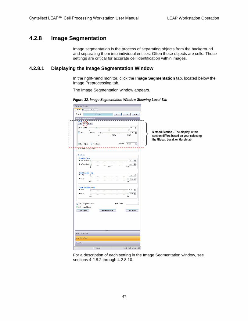
4.2.8 Image Segmentation
Image segmentation is the process of separating objects from the background and separating them into individual entities. Often these objects are cells. These settings are critical for accurate cell identification within images.
4.2.8.1 Displaying the Image Segmentation Window
In the right-hand monitor, click the Image Segmentation tab, located below the Image Preprocessing tab.
The Image Segmentation window appears.
Figure 32. Image Segmentation Window Showing Local Tab
For a description of each setting in the Image Segmentation window, see sections 4.2.8.2 through 4.2.8.10.
Method Section – The display in this section differs based on your selecting the Global, Local, or Morph tab

Cyntellect LEAP™ Cell Processing Workstation User Manual LEAP Workstation Operation
48
4.2.8.2 Method Section
In the Image Segmentation window, the Method section changes depending on whether you have selected the Global, Local, or Morphology tab.
4.2.8.2.1 Global Threshold (intensity)
The Threshold settings that are located in the Global tab apply equally across the entire image. It works best when the background is uniform and even across the entire image. A minimum grey level can be set as well as a maximum grey level. The resulting black and white binary image will define the areas that possess intensity values above the Min Grey and below the Max Grey levels (white). The black regions represent the areas where the pixel intensities are below the minimum and above the maximum.
Min Grey – Separates objects from the background signals within the images.
Max Grey – Typically used to prevent very high intensity objects (i.e., saturated) from being further processed.
Auto button – The software will automatically adjust the Min Grey levels for each image.
Figure 33. Min Grey
Min Grey Too Low Min Grey Too High
Cyntellect LEAP™ Cell Processing Workstation User Manual LEAP Workstation Operation
49
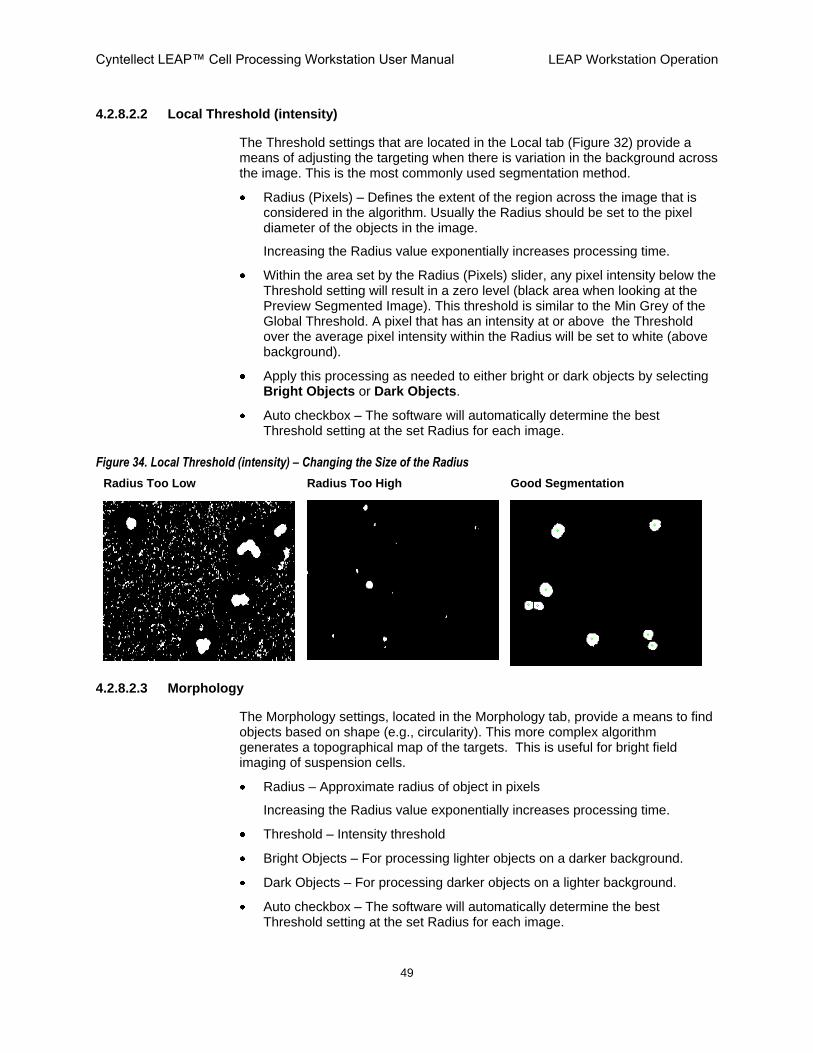
4.2.8.2.2 Local Threshold (intensity)
The Threshold settings that are located in the Local tab (Figure 32) provide a means of adjusting the targeting when there is variation in the background across the image. This is the most commonly used segmentation method.
Radius (Pixels) – Defines the extent of the region across the image that is considered in the algorithm. Usually the Radius should be set to the pixel diameter of the objects in the image.
Increasing the Radius value exponentially increases processing time.
Within the area set by the Radius (Pixels) slider, any pixel intensity below the Threshold setting will result in a zero level (black area when looking at the Preview Segmented Image). This threshold is similar to the Min Grey of the Global Threshold. A pixel that has an intensity at or above the Threshold over the average pixel intensity within the Radius will be set to white (above background).
Apply this processing as needed to either bright or dark objects by selecting Bright Objects or Dark Objects.
Auto checkbox – The software will automatically determine the best Threshold setting at the set Radius for each image.
Figure 34. Local Threshold (intensity) – Changing the Size of the Radius
Radius Too Low Radius Too High Good Segmentation
4.2.8.2.3 Morphology
The Morphology settings, located in the Morphology tab, provide a means to find objects based on shape (e.g., circularity). This more complex algorithm generates a topographical map of the targets. This is useful for bright field imaging of suspension cells.
Radius – Approximate radius of object in pixels
Increasing the Radius value exponentially increases processing time.
Threshold – Intensity threshold
Bright Objects – For processing lighter objects on a darker background.
Dark Objects – For processing darker objects on a lighter background.
Auto checkbox – The software will automatically determine the best Threshold setting at the set Radius for each image.

Cyntellect LEAP™ Cell Processing Workstation User Manual LEAP Workstation Operation
50
4.2.8.3 Preview Segmented Image
Preview Segmented Image will change the currently displayed image to a binary (black and white) image representing the segmentation before applying any of the Noise Gates filters in section 4.2.8.4. Grey pixel areas will be changed to either black or white. Black is ignored as background. White pixel areas can be subsequently segmented as objects using the Noise Gates filters.
4.2.8.4 Noise Gates Section
The following selections are located in the Image Segmentation window‟s Noise Gates section.
4.2.8.4.1 Object Size Range
It is possible to select to filter the objects found, after the previous threshold operations, based on size. Only objects (e.g., cells) that are greater than the Min Area (Pixels) and less than the Max Area (Pixels) will be left within the segmented image.
4.2.8.4.2 Object Elongation Range
The Object Elongation Range filter may be suitable when a mixture of adherent and semi adherent cells are present because it is a calculation of each object of the major axis over the minor axis.
A value of 1 is equal to a perfect circle and as the value increases the object is more oval shaped.
4.2.8.4.3 Object Compactness Range
The Object Compactness Range filter is a ratio of the derived perimeter (based on the radius of the object) and the actual perimeter.
A value of 1 is equal to a perfect circle and as the value increases the object contains multiple „fingers‟. For example a lymphocyte would have a small value and a dendrite would have a large value.
4.2.8.5 Separate Touching Objects
Select the Separate Touching Objects checkbox to apply a watershed algorithm to separate touching objects.
4.2.8.6 Objects Found
Objects Found refers to the number of objects found using the current image segmentation settings.
4.2.8.7 Auto Update Objects
Select the Auto Update Objects checkbox to immediately update the target display upon changing any image segmentation setting.

Cyntellect LEAP™ Cell Processing Workstation User Manual LEAP Workstation Operation
51
4.2.8.8 Clear Objects
Clicking on this button will remove the green labeled objects from the displayed image. Once cleared, the laser will have no targets to shoot.
4.2.8.9 Find Objects
By clicking the Find Objects button, the computer will update the target display with the current image segmentation setting. This button is useful when Auto Update Objects is not checkmarked (Figure 32 in section 4.2.8.1).
4.2.8.10 Find Objects Report
Find Objects Report will provide detailed information (Figure 35) on the objects found by the segmentation algorithms. You can then copy and paste the data into a Microsoft Excel workbook.
Figure 35. Object (Blob) Report

Cyntellect LEAP™ Cell Processing Workstation User Manual LEAP Workstation Operation
52
4.2.9 Object Indicator
The Object Indicator (Figure 36 circled item) is a menu located in the upper menu bar on the right-hand monitor. Object Indicator (Figure 36) provides a display of a crosshair, dot, or outline on all found objects. For the display to appear, make sure that the Object Indicator is toggled On (green). The cross, dot, or outline is always green. In the following example, Dot is shown in the menu.
Figure 36. Object Indicator
Crosshair Dot Outline
4.2.10 Focus Map
The Focus Map feature fits a 3D curve in the Z axis to the plate based on the focus of points (wells) that you select.
You can choose to use the Focus Map instead of Autofocus during processing. (See individual Application Guides.)
If both Autofocus and the Focus Map are selected when the plate is processed, the software will use the Focus Map as a starting point for the focus and then refocus on each well.
Object Indicator menu
Toggle On (green) for your selection to take effect

Cyntellect LEAP™ Cell Processing Workstation User Manual LEAP Workstation Operation
53
4.2.10.1 Selecting a Focus Point
1. Go to a well.
2. Autofocus.
3. Right-click over the well and then select Set Focus Point (Figure 37).
Figure 37. Focus Map
A black ring outlines the well selected as a focus point.
It is recommended that you use at least five points for the Focus Map. Make sure that Focus Map: Enabled is displayed at the far left corner in the workflow (left-hand) window.
Figure 37 shows a 384-well plate with all wells selected for processing (orange rings) and six wells selected for the Focus Map (black rings).
In Figure 37, six points are used at C3, C22, H12, I13, N3 and N22.
4.2.10.2 Clearing a Focus Point
Right-click the well and select Clear Focus Point.
4.2.10.3 Deleting all Focus Points
Anywhere on the plate map view, right-click and select Clear Focus Map.
Six Wells Selected for Focus Map

Cyntellect LEAP™ Cell Processing Workstation User Manual LEAP Workstation Calibration
54
5. LEAP Workstation Calibration
This chapter describes how to calibrate the LEAP workstation.
Perform laser centering daily if the laser will be used for targeted shooting.
Perform laser targeting as indicated by laser centering.
Perform laser spot size calibration as needed to empirically confirm laser spot sizes.
5.1 Laser Centering
When you perform laser centering, you run the wizard using the laser wavelength and magnification to be used during the experiment.
Perform laser centering using the Laser Center Wizard as follows.
1. Load a plate and select Target Calibration Slide.
2. Insert the calibration mirror with the silver side facing up.
3. Open the Machine Control Tab (left screen).
4. In the Machine Control Tab, do the following:
a. Select the magnification and laser wavelength to be used during the experiment.
b. Set the laser spot size (beam expander) to the experimental setting. (If you will be using a range of spot sizes, choose a value that is within this range.) (see spot size curve).
c. Set the laser power (laser attenuator) to the experimental setting. (If you will be using a range of power, choose a value that is within this range.) (see previous power curve).
5. Open the Plate Tab (left screen).
6. In the Plate Tab, do the following:
a. In the plate view display, move to a location with spots or to the side of the mirror.
b. Click on the camera icon to view (right screen).
c. Adjust the exposure and gain so that there are gray pixels in image.
d. Autofocus.
7. Open the Machine Control Tab (left screen).
8. In the Machine Control Tab, click the X and Y position arrows to move to a blank area on the mirror.
9. Under the Calibration menu (left screen), click Laser Center Wizard.
10. Perform the instructions in the yellow part of the window.

Cyntellect LEAP™ Cell Processing Workstation User Manual LEAP Workstation Calibration
55
11. Draw a grid over the Field of Regard (FOV) and shoot with the Manual Laser Targeting application, using the following selections:
Laser power at experimental setting.
Beam expander at experimental setting.
12. Do one of the following:
If the laser spots and grid overlap accurately, proceed with your experiment.
If the laser spots and grid do not overlap accurately, perform Laser Targeting Calibration Wizard per section 5.2.
When making this overlap comparison, be sure to be using a snapped image. This is because snapped images have been dewarped, as required for laser targeting.
5.2 Laser Targeting
Perform Laser Targeting if the laser spots and grid did not overlap accurately during Laser Centering in section 5.1.
1. Use the Laser Targeting Calibration wizard, making the following selections:
Laser power at experimental setting.
Beam expander at experimental setting.
2. Verify the results by again drawing a grid over the FOV and shooting with the Manual Laser Targeting application.
5.3 Laser Spot Size Calibration
When you perform laser spot size calibration, you use the Laser Spot Size Calibration wizard to generate the beam expander-laser spot size curve.
The LEAP workstation comes with a beam expander-laser spot size curve from the factory. This curve will not change and there is no need to run this wizard on a regular basis. Indeed, if the focus plane is not chosen carefully, the beam expander curve-laser spot size curve will be inaccurate and lead to inaccurate laser spot sizes estimates. The user can use this wizard to empirically confirm laser spot sizes if needed.
1. Load the target calibration slide.
2. Load Low or High Mag Brightfield Calibration settings (right screen, low for 3X and 5X, high for 10X and 20X).
3. Open the Plate Tab (left screen).
4. In the Plate Tab, do the following:
a. Click on the plate to move to a location with spots or to the side of the mirror.
b. Click on the camera icon to view (right screen).
c. Adjust the exposure and gain so that there are gray pixels in image.

Cyntellect LEAP™ Cell Processing Workstation User Manual LEAP Workstation Calibration
56
d. Autofocus.
5. Open the Machine Control Tab (left screen).
6. In the Machine Control Tab, do the following:
a. Select the same magnification to be used during experiment.
b. Select laser wavelength to be used during experiment.
c. Prior to starting the Laser Spot Size Wizard, set the Beam Expander to a value that is -2 from the minimum spot size value. For example, if the minimum spot size setting for the beam expander is -1.5, set the beam expander to -3.5. The goal is to have a large spot to focus on during the Laser Spot Size Wizard. This will give more consistent focusing.
d. Set the laser attenuator to a value corresponding to 10 µJ for green laser, or full power for UV laser (see power curve).
7. Under the Calibration menu (left screen) click Laser Spot Size Calibration Wizard.
8. Perform the instructions in the yellow part of the window, using the following guidelines:
Enter a range of beam expander settings that brackets the previous minimal spot size +/- 1.5 mm.
Refocus until the Delta (change in microns) is less than 5. When setting the threshold value, adjust until the edges are clearly defined and the entire object is selected.
The final output will be a graph of Spot Radius (pixels) vs. Beam Expander Position (mm). This graph will be saved and is accessible under the Calibration -> Laser Spot Size Wizard Menu.
The smallest beam size is reposted as the minimum of the data (red marker). To use a larger spot size, always use a Beam Expander value to the left of the minimum.

Cyntellect LEAP™ Cell Processing Workstation User Manual LEAP Workstation Applications
57
6. LEAP Workstation Applications
This chapter provides a brief description of the applications available for use on the LEAP workstation.
6.1 Introduction
Applications are used to encapsulate the various operations of data acquisition and laser targeting parameters for specific applications. Common components, such as segmentation and camera settings, are constant across all of the applications. Components specific to each application are available only when that specific application is selected.
There are a variety of applications available for the LEAP workstation, and new ones continue to be developed. Each application is described in a separate Application Guide. New applications can be added by installing the application via a CDROM installation disk.
The LEAP workstation comes with the following core set of applications pre-installed (additional applications are available):
Cell Counting
Cell Purification
Cell Viability
Automated Laser Targeting
Manual Laser Targeting
See the specific Application Guides for details on each application.
Data from each of these applications is available to the Results Viewer application. The Results Viewer allows the viewing and exporting of data collected on the LEAP workstation. See the LEAP™ Results Viewer Application Guide.

Cyntellect LEAP™ Cell Processing Workstation User Manual Filter Configuration
58
Appendix A Filter Configuration
This appendix provides the list of standard filters used on the LEAP workstation.
Table 7. Standard Filters on LEAP
Excitation (nm) Dichroic (nm) Emission (nm) Common Dyes
377/50 409 LP 438/24 DAPI, Hoechst, Alexa Fluor 350, Aminomethylcoumarin, Lysosensor Blue, Marina Blue, Pacific Blue, BFP, EBFP
438/24 458 LP 483/32 AmCyan, CFP, ECFP, BOBO-1, SYTOX Blue
472/30 495 LP 520/35 Cy2, CyQuant, DiO, YOYO-1, GFP, EGFP,
482/35 506 LP 536/40 Carboxyfluorescein. FITC, Alexa Fluor 488, Calcein, Fluo-4, Mitotracker Green, Oregon Green, Rhodamine 110, rsGFP
525/40 555 LP 585/40 Rhodamine, TMR, TRITC, Alexa Fluor 532, 5-TAMRA, Dil, POPO-3, PO-PRO-3,
531/40 562 LP 593/40 Alexa Fluor 546, Alexa Fluor 555, Calcium Orange, Cy3, LysoTracker Yellow, MitoTracker Orange, Phycoerythrin (PE), dsRed
562/40 593 LP 624/40 Propidium Iodide (PI), Cy3.5, Alexa Fluor 568, Alexa Fluor 594, Calcium Crimson, MitoTracker Red, Texas Red, HcRed
628/40 660 LP 692/25 Cy5, Alexa Fluor 647, Alexa Fluor 660, APC (Allophycocyanin), BODIPY 650/665, DiD, SYTO Red 60, 62, 63, TOTO-3
Optional Filters Available for Installation by Cyntellect
500/24 520 LP 542/27 Calcium Green, Fluo-3, Rhodamine 123, YFP

Cyntellect LEAP™ Cell Processing Workstation User Manual Power and Spot Size Data Examples
59
Appendix B Power and Spot Size Data Examples
This appendix shows examples of power and spot size data.
B.1 Green and UV Lasers
Figure 38. Laser Energy Measurement vs. Laser Attenuator Position – First Worksheet Example
The first worksheet shows the data and graphs.

Cyntellect LEAP™ Cell Processing Workstation User Manual Power and Spot Size Data Examples
60
Figure 39. Laser Energy Measurement vs. Beam Expander Position – Second Worksheet Example
The second worksheet shows the µJ power and attenuator angle settings.

Cyntellect LEAP™ Cell Processing Workstation User Manual Power and Spot Size Data Examples
61
Figure 40. Green Laser Spot Size Calibration Example
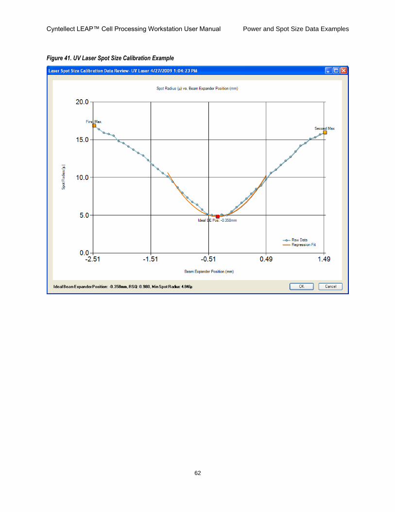
Cyntellect LEAP™ Cell Processing Workstation User Manual Power and Spot Size Data Examples
62
Figure 41. UV Laser Spot Size Calibration Example

This page intentionally blank

Cyntellect, Inc. 6620 Mesa Ridge Road San Diego, CA 92121 Direct: 858.875.1600 Toll Free: 877.584.9150 Fax: 858.875.1610 E-mail: [email protected] Web Site: www.cyntellect.com