lean methodology to transform shipbuilding panel · pdf filejournal of ship production and...
TRANSCRIPT

Journal of Ship Production and Design, Vol. 33, No. 1, February 2017, pp. 1–10http://dx.doi.org/10.5957/JSPD.33.1.160028
Lean Methodology to Transform Shipbuilding Panel Assembly
Damir Kolich,* Richard L. Storch,† and Niksa Fafandjel*
*Naval Architecture and Ocean Engineering Department, University of Rijeka, Rijeka, Croatia†Industrial and Systems Engineering Department, University of Washington, Seattle, Washington
The core competence of any medium-to-large sized shipyard includes the panelassembly line. Ship panels are the basic building blocks of well over 60% of theinterim products of typical commercial ships. Therefore the improvement of thepanel assembly process could greatly reduce the number of man-hours of allassembled panels, thereby yielding significant savings to the shipyard. Using a leanmethodology to make kaizen improvements to traditional panel assembly lines willgreatly reduce the costs in ship production. This means that shipyards, which arebarely keeping earnings above costs, will be able to increase profits. Value streammapping is a key way of determining how lean a production process is. Thewastes in production assembly are readily identified as well as the takt time andthe areas where there is push as opposed to pull. In this paper, a case study of atypical commercial shipyard, which builds a product mix of vessels is analyzed.The present state panel assembly line is mapped and then using lean tools andavant-garde technologies, such as hybrid laser arc welding, the new transformedpanel assembly line is demonstrated to bring man-hour reductions of over 80%, sothat a typical panel is assembled using 12 man-hours as opposed to the present72 man-hours.
Keywords: value stream mapping; shipbuilding; one-piece flow; kaizen; hybrid-laserarc welding
1. Introduction
THE CORE competence of virtually any medium-to-large sizedshipyard includes a panel assembly line. Many times shipyardmanagement takes for granted that the panel assembly line is justfine as is and therefore it is not necessary to make analysis toimprove this core shipbuilding assembly process any further. How-ever, since flat panels make up well over 60% of the buildingblocks of most commercial ships, any type of significant improve-ment to the panel assembly line will result in important costsavings for the shipyard.Lean manufacturing is a concept that is used in multiple indus-
tries to improve the production processes by streamlining them.The techniques include applying the principles of value streammapping. Once the value stream of the present production systemis mapped, it is possible to readily identify the wastes. The identi-
fied wastes need to be eliminated for the future improved valuestream map. Likewise it is necessary to have a balanced takt timebetween the processes. In addition, the lean principles of one-pieceflow, kaizen, and just in time assembly need to be implemented.
2. Background
Storch and Lim (1999) introduced the concept of lean manufactur-ing to the shipbuilding industry and stressed the importance of flowas key to the lean manufacturing analysis system. Likewise, theapplication of group technology within a product work breakdownstructure as opposed to an exclusively ship breakdown based onfunctions are some of the necessary fundamentals that need to bedeveloped at any shipyard in order to be able to make leanimprovements. The definition of lean shipbuilding further definesand applies the ideas of lean manufacturing from the automobileindustry, especially the Toyota Production System with the two pil-lars of just in time and built-in quality (Bicheno & Holweg 2000).
Manuscript received by JSPD Committee July 7, 2016; accepted September17, 2016.
FEBRUARY 2017 JOURNAL OF SHIP PRODUCTION AND DESIGN 12158-2874/17/3301-0001$00.00/0

Defining the value stream is stressed as are the seven wastesof overproduction, transportation, waiting, inventory, defects, overprocessing, and movement (Liker & Lamb 2002). With Koenig,Narita and Baba (2002) and Okomuto (1997), the idea about one-piece flow is well explained within the panel assembly process ofthe Japanese IHI shipyard. The underlying idea behind these papersis the need to improve the efficiency of core shipbuilding processesin order to be competitive in the unmerciful industry, where manyEuropean shipyards have seen bankruptcies and closures. The ideais that even though a shipyard may be technologically superior,by failing to apply a lean philosophy will eventually lead tononcompetitiveness on the world stage.
A lean methodology was made which applied the idea of theearlier papers and demonstrated through Gantt charts and throughthe comparison of different types of panel and built-up panelassembly methods in order to uncover the most efficient assemblymethod. Through the use of a Monte Carlo risk analysis tech-nique, it was shown that the panel-block assembly method withthe least amount of weld lengths and through the utilization ofone-piece flow and one-sided welding of steel plates results inthe fewest number of man-hours (Kolich et al. 2011b, 2012a). Inanother paper, a value stream mapping methodology of pre-assembly steel processes was developed. This demonstrated theapplication of lean principles in shipyard storage and productionareas, where the system appears to function efficiently, could befurther improved (Kolich et al. 2012b). In another paper, the valuestream mapping method was adapted for micropanel assembly.With the use of clustering that derives from the data-mining field,it is possible to further simplify the present shipyard productionprocesses and determine which production processes can be com-bined together, thereby reducing the amount of space taken upin the shipyard. This results in man-hour reductions of up to 50%(Kolich et al. 2014). Likewise, data mining to predict hybrid laser
arc welding (HLAW) improvements is another argument for apply-ing better technology to processes where there is a bottle neckwhich needs to be removed (Kolich et al. 2015b). Finally, thepaper on optimizing interim product assembly using value streammapping is another demonstration of using typical lean toolsadapted for the shipbuilding industry (Kolich et al. 2015a).
3. Shipyard case study
The shipyard analyzed in this paper is considered a medium-to-large sized shipyard in the European theater of shipbuilding. Itbuilds a product mix of vessels ranging from chemical tankers,asphalt tankers, and asphalt barges. It has picked up the nichemarket and delivers up to 31 barges a year, with the capacity forhaving a diverse shipbuilding program. Although the shipyardhas decent production facilities that meet the needs of the produc-tion product mix program, it is necessary for it to improve itsfacilities in order to maintain and also increase its competitive-ness. According to the SNAME Design for Production (DFP)Manual (1999), it is necessary to analyze the product mix of vesselsand determine where improvements can be made. DFP principlescan be adhered to make significant improvements (Kolich et al.2010, 2011a). Even though the shipyard uses a degree of a productwork breakdown structure, still much of the initial design is stillbased on functional drawings and functional breakdown when itcomes to vessel price estimation.
The shipyard in question is in Europe and presently has a prod-uct mix program of chemical tankers and asphalt barges (Figs. 1and 2) (Kolich et al. 2015a). It launches vessels from two slipways,which are serviced by an overhead gantry crane with a capacity of300 tons lifting capacity. This means that the erection blocks areusually designed to be close to 300 tons in weight. The rest of thefacilities are structured around steel storage and handling, steel pre-fabrication processes, steel fabrication processes, steel assembly,and outfitting. Then there is interim product assembly of panels,micropanels, and built-up panels in the subassembly hall. Thisassortment of interim products is combined to form sections, andfinally the large blocks, which are erected on the slipway. There isa degree of integrated hull construction, outfitting, and paintingperformed in the assembly halls. This includes pipe hangers, pipes,and other types of steel outfitting such as ladders and ventilationducts. The aim of the shipyard is to reduce the amount of outfittingprocesses after the erection phase. The typical ships are made upof the following characteristics in Table 1.
The purpose of this paper is to analyze and map the shipyardpanel assembly process, upon which it will be possible to deductthe existing wastes and then with the application of lean principlesand value stream mapping tools, draw up a new improved future
Fig. 1 Profile view of 49,000/51,000 dwt oil tanker for unmanned oilproducts and chemicals 2,400 dwt unmanned oil asphalt tank barge
(3. Maj Shipyard Archive, 2010)
Fig. 2 Profile view of 2400 dwt unmanned oil asphalt tank barge (3. Maj Shipyard Archive 2015)
2 FEBRUARY 2017 JOURNAL OF SHIP PRODUCTION AND DESIGN
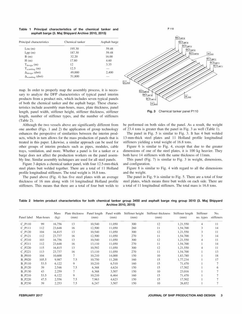
map. In order to properly map the assembly process, it is neces-sary to analyze the DFP characteristics of typical panel interimproducts from a product mix, which includes seven typical panelsof both the chemical tanker and the asphalt barge. These charac-teristics include assembly man-hours, mass, plate thickness, panellength, panel width, stiffener height, stiffener thickness, stiffenerlength, number of stiffener types, and the number of stiffeners(Table 2).Although the two vessels above are significantly different from
one another (Figs. 1 and 2) the application of group technologyenhances the perspective of similarities between the interim prod-ucts, which in turn allows for the mass production of panels that istreated in this paper. Likewise, a similar approach can be used forother groups of interim products such as pipes, modules, cabletrays, ventilation, and more. Whether a panel is for a tanker or abarge does not affect the production workers on the panel assem-bly line. Similar assembly techniques are used for all steel panels.Figure 3 depicts a chemical tanker panel, with four 12.5-mm-thick
steel plates butt welded together. There are a total of 11 Hollandprofile longitudinal stiffeners. The total weight is 16.8 tons.The panel above (Fig. 4) has five steel plates with an average
thickness of 16 mm along with 14 longitudinal Holland profilestiffeners. This means that there are a total of four butt welds to
be performed on both sides of the panel. As a result, the weightof 23.4 tons is greater than the panel in Fig. 3 as well (Table 1).
The panel in Fig. 5 is similar to Fig. 3. It has 4 butt welded13-mm-thick steel plates and 11 Holland profile longitudinalstiffeners yielding a total weight of 16.8 tons.
Figure 6 is similar to Fig. 4, except that due to the greaterdimensions of one of the steel plates, it is 100 kg heavier. Theyboth have 14 stiffeners with the same thickness of 11mm.
This panel (Fig. 7) is similar to Fig. 3 in weight, dimensions,and configuration.
Figure 8 is similar to Fig. 4 with regard to all the dimensionsand the weight.
The panel in Fig. 9 is similar to Fig. 5. There are a total of foursteel plates, which means three butt welds on each side. There area total of 11 longitudinal stiffeners. The total mass is 16.8 tons.
Table 1 Principal characteristics of the chemical tanker andasphalt barge (3. Maj Shipyard Archive 2010, 2015)
Principal characteristics Chemical tanker Asphalt barge
Loa (m) 195.30 59.48Lpp (m) 187.30 59.48B (m) 32.20 16.00H (m) 17.80 4.60Tdesign (m) 12 3.35Tscantling (m) 12.5 —Δdesign (dwt) 49,000 2,400Δscantling (dwt) 51,800 —
Table 2 Interim product characteristics for both chemical tanker group 3450 and asphalt barge ring group 3510 (3. Maj ShipyardArchive 2010, 2015)
Panel label Man-hoursMass(kg)
Plate thickness(mm)
Panel length(mm)
Panel width(mm)
Stiffener height(mm)
Stiffener thickness(mm)
Stiffener length(mm)
Stiffenerno. types
No.stiffeners
C_P110 99 16,756 13 10,540 11,050 300 12 1,21,550 4 11C_P111 112 23,648 16 12,500 11,050 260 11 1,54,700 3 14C_P120 104 16,815 13 10,540 11,050 300 12 1,21,550 3 11C_P121 112 23,737 16 12,500 11,050 270 11 1,54,700 3 14C_P210 103 16,756 13 10,540 11,050 300 12 1,21,550 4 11C_P211 112 23,648 16 13,110 11,050 270 11 1,54,700 1 14C_P220 115 16,815 13 10,592 11,050 300 12 1,21,550 4 11C_P221 113 23,737 16 13,110 11,050 270 11 1,54,700 1 13B_P010 104 10,600 7 10,210 14,000 150 10 1,83,780 1 18B_P020 105.5 9,987 7.5 10,750 11,200 160 15 1,77,234 1 17B_P110 53.5 6,122 9 10,210 6,510 160 15 71,470 1 7B_P120 39 2,546 7.5 6,368 4,624 150 15 17,502 1 6B_P130 43 2,259 7 6,368 3,507 150 10 23,016 1 7B_P210 53.5 6,122 9 10,210 6,464 160 15 71,470 1 7B_P220 47.5 2,556 7.5 7,963 4,623 150 15 17,502 1 7B_P230 39 2,253 7.5 6,247 3,507 150 10 26,852 1 7
Fig. 3 Chemical tanker panel P110
FEBRUARY 2017 JOURNAL OF SHIP PRODUCTION AND DESIGN 3
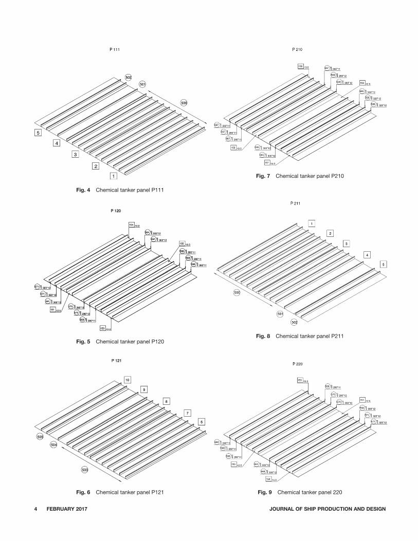
Fig. 4 Chemical tanker panel P111
Fig. 5 Chemical tanker panel P120
Fig. 6 Chemical tanker panel P121
Fig. 7 Chemical tanker panel P210
Fig. 8 Chemical tanker panel P211
Fig. 9 Chemical tanker panel 220
4 FEBRUARY 2017 JOURNAL OF SHIP PRODUCTION AND DESIGN

Figure 10 is virtually identical to Fig. 8 except for being slightlyheavier due to small steel plate dimensional discrepancies in length.Although the panels of the asphalt tanker have many similari-
ties, it is helpful to analyze the panels of the barge, becausethe workers on the panel assembly line have an identicalapproach, which is in compliance with group technology andlean manufacturing.The panel of Fig. 11 contains five steel plates butt welded together
with 18 longitudinal stiffeners. The panel has a total mass of 10.6 tons.The panel in Fig. 12 contains seven steel plates butt welded
together. There are a total of 14 stiffeners and the total stiffenerlength is 177 meters. The total panel weight is 9.99 tons.This panel Fig. 13 contains three steel plates butt welded
together with a total mass of 6.1 tons.The above panel in Fig. 14 contains two steel plates with a
total mass of 2.6 tons, which is logically lighter in weightbecause of the smaller number of steel plates.The panel in Fig. 15 has two steel plates with a total mass of
2.3 tons, which is lighter than the previous panel (Fig. 14) due tothe smaller thickness of the steel plates.
Fig. 10 Chemical tanker panel 221
Fig. 11 Barge panel 220
Fig. 12 Barge panel 020
Fig. 13 Barge panel P110
Fig. 14 Barge panel P120
FEBRUARY 2017 JOURNAL OF SHIP PRODUCTION AND DESIGN 5

The panel in Fig. 16 consists of three steel plates and sevenlongitudinal stiffeners with a total weight of 6.1 tons.
The panel of Fig. 17 consists of a total of two steel plates withand seven longitudinal stiffeners giving a total weight of 2.6 tons.Figure 17 has a similar weight and configuration as Fig. 10 above.Although Fig. 17 has seven stiffeners and Fig. 14 has six, the totallength of the stiffeners is the same (Table 1).
The panel in Fig. 18 consists of two steel plates and six stiff-eners with a mass of 2.3 tons as Fig. 15.
4. Value stream mapping
Applying the lean principle of kaizen goes hand in hand withfurther development of DFP principles along with the need to
institute and apply lean principles in the production system. Thelean principles of determining the value stream and mapping it inorder to determine where there is waste are one of the first stepsin making the production process more efficient. A logical placeto begin this value stream mapping is the panel assembly linesince between 60% and 80% of the vessels’ interim products con-stitute flat panels.
The key value stream mapping symbols include identifying thesupplier and customer, which uses the symbol to the top left ofthe value stream mapping legend of Fig. 19. Then it is necessaryto identify where there is interim storage. The interim storage isrepresented by a triangle. Then there is a push arrow as seen inthe legend. A thin straight line with an arrowhead representsmanual information. A zigzag thin line represents electronicinformation. The kaizen improvement burst represents an irregular
Fig. 15 Barge panel P130
Fig. 16 Barge panel P210
Fig. 17 Barge panel P220
Fig. 18 Barge panel P230
6 FEBRUARY 2017 JOURNAL OF SHIP PRODUCTION AND DESIGN

figure within, which is placed descriptive text of the necessaryplanned improvement within the future improved value streammap. The withdrawal kanban looks like an index card and repre-sents the instructions, which dictate to the production when toremove interim products from the supermarket to the next pro-duction process. The kanban post indicates a location where thewithdrawal kanban exists. The kanban pull signal demonstratesthe signal that comes from the next downstream process when itis ready to receive the next interim product. The pull arrow indi-cates the movement of the interim product to the downstreamprocess. Finally, the process boxes have a title and indicatewhether the process is a nonvalue added process or a value addedprocess. The data box indicates the takt time of the process, thenumber of operators, the number of interim products per shift,and the man-hours.
4.1. Current state
The value stream map is always read from left to right(Fig. 20). At the top left corner is the supplier or in this case theinternal predecessor of the production system. The steel platesprior to arriving to the panel assembly line have been sortedlabeled, heated, grit blasted, primer covered, and then cut to thenecessary specifications ready to be assembled at the panelassembly line. However, the steel plates are stacked at an interimstorage area in the consecutive order necessary to be assembledat the panel assembly line. At workstation number 1, the firststeel plate is tack butt welded to the second steel plate. Then athird steel plate is aligned and tack butt welded to the secondplate. Then a fourth steel plate is removed from the interim storageand then butt welded to the third steel plate. Then the tack butt-welded panel is transported along rollers to the second work sta-tion where the seams are completely butt welded to along theseams that were just tack welded on station one. A panel with four
steel plates requires three butt welds. The simple equation to deter-mine the number of butt welds for a panel is:
W ¼ S � 1 ð4:1Þ
where W is the number of butt welds, S is the number of seams.Afterward, the panel is turned over to have the same seams on
the other side butt welded in order to complete the panel butt-welding cycle. The shipyard uses two-sided welded technologyas opposed to one-sided welding technology, which results inquality welds. However, if the shipyard were to transform to one-sided welding technology, it would result in less movements, asmaller duration time and therefore fewer man-hours, thus greatersaving. Because of this requirement to turn the panel to the otherside, the ceiling at workstation number 2 is higher than at theother workstations where there is no need to flip the panel overanymore. At workstation 3, the positions of where the longitudi-nal stiffeners need to be added are marked with string and chalktechnology manually. Then those positions are grinded down untilhe primer paint is removed and the steel finish is visible. In thisway, the stiffeners get welded with greater speed and better qual-ity, thus improving efficiency. Once this is done, at workstationnumber four the first longitudinal stiffener is centered on the cor-responding freshly grinded position. Then hydraulic pins pressdown on the first stiffener and again double-sided submerged arcwelding technology is used to weld the stiffener to the panel.This is repeated until all of the stiffeners are welded to the panel.Please note that due to the use of the hydraulic pins, it is not nec-essary to first tack weld. The tack welding step is eliminated thussaving time, energy, and decreasing the number of motions. Thetakt time is usually determined by the fourth workstation, whichis defined as the bottleneck station. This is due to the fact thatthere are usually between 6 and 18 stiffeners with total weldinglengths ranging between 17 and 183 meters (Table 2).
Fig. 19 Legend of value stream mapping symbols (Kolich et al. 2015a)
FEBRUARY 2017 JOURNAL OF SHIP PRODUCTION AND DESIGN 7

The formula for calculating the assembly duration time of thefirst panel is as follows:
DTTotal ¼ DT1 þ DT2 þ DT3 þ DT4 þ DT5 ð4:2ÞThe man-hours are calculated by multiplying the duration timeof each process with the number of operators. Therefore thefollowing calculation is pertinent: (4 hours � 5 operators) þ(4 hours � 4 operators) þ (4 hours � 5 operators) þ (4 hours �4 operators) ¼ 72 hours. See equation (4.3).
Man-hoursTotal ¼ DT1 � O1 þ DT2 � O2 þ DT3 � O3
þ DT4 � O4 þ DT5 � O5 ð4:3Þwhere DTTotal is the total duration time, DT1–5 are the individualprocess duration times, and O1–5 are the number of operators.
4.2. Future state
The transformation of the current state starts by analyzingwhere there are wastes. For example, the triangles represent wasteand need to be replaced with a kanban supermarket system ofhandling interim products among the processes. Likewise, it isnecessary to analyze where there is push and replace it with pull.Presently at the shipyard, the steel plates are stacked in big piles.As a result, the steel plates start to corrode and even developdeformations. Therefore, the assembly of these steel plates alongthe panel assembly line means that there will be problems in level-ing the steel, which translates to extra hours of rework and evenincreases the takt time of the panel assembly process. The kanbanworks in a similar way to modern supermarkets. For instancesupermarkets place enough items as is demanded by customers forthat day. However, in case more items of a particular product get
used up, then the supermarket has a kanban card, which specifieswhen the minimum amount of a specific item has been achieved.Then the employee responsible for restacking the items brings theamount written on the kanban card. The same is with the panelassembly line where steel plates are restacked only when a mini-mum number have been used up. Therefore, the stacks of manysteel plates will be eliminated in the future transformed state. Thismeans that there will be more room in the shipyard and less deteri-oration of steel plates.
The principle of one-piece flow means that instead of assem-bling all of the steel plates together into one big plate as is done inmost shipyards, each unit plate comes under a specially designedgantry, which has the computer information as to placing the exactnumber of stiffeners onto the unit plate. Since each unit plate doesnot have more than four stiffeners due the width constraints, it iseconomically viable to fasten, and weld all of the stiffeners simul-taneously using submerged arc welding or even HLAW technol-ogy. On the other hand, mounting and welding up to 15 stiffenerson the traditional panel assembly line simultaneously is not eco-nomically or technologically viable, because that would require amuch larger gantry with up to 15 automated welding machines.This requires a costly solution for investment as well as morespace. Using the one-piece flow principal and creating a balancedtakt time means that it is necessary to update the technologywithout doing “overkill” as would be the situation with the largetraditional panel assembly line. Therefore, on the first worksta-tion, the three to four stiffeners are tack welded simultaneously.There is only one operator. Afterward, the unit plate with tackwelded stiffeners is sent to workstation 2 where it is automaticallywelded. Likewise, there is only one operator who controls andsupervises the operation. At work station, three is where the widthof the assembly increases in order to accept more stiffened unit
Fig. 20 Present state value stream map (Kolich et al. 2015a)
8 FEBRUARY 2017 JOURNAL OF SHIP PRODUCTION AND DESIGN

panels. The takt time is 1 hour per work station. At the third work-station, the first unit panel is positioned such that the other threestiffened unit panels can be butt welded as they arrive from work-station 2. Therefore, the man hours are 3 þ 3 þ 3 þ 3 ¼ 12 man-hours. The duration time is 6 hours, which is a 62.5% decreasefrom 16 hours. Likewise, the man-hours are 12 hours, which is an83% decrease from 72 hours. The savings are considerable andjustify undertaking a transformation. In addition to man-hour andduration time improvements, there are also space savings, sinceinstead of four work stations there are three. Likewise, the firsttwo work stations have a decrease in width to 1-unit steel plate asopposed to 5-unit steel plates (see Fig. 21).
5. Discussion and conclusion
The value stream mapping transformation results in a panelassembly process where there is one-piece flow, pull, balancedflow, and an equal takt time. In addition, the advancement of thewelding technology from classic metal active gas welding toHLAW means that excessive movements are eliminated. It is notnecessary to turn the panel onto the other side to get welded sinceHLAW butt welds on one side. The penetrations of HLAW aredeep and quality enough so that it becomes unnecessary to turnover to the other side to weld. The stiffening of unit steel plates asopposed to large welded steel plates is much more practicable froma technological point of view. Simultaneously up to four stiffenersare welded to each unit plate, resulting in a stiffened unit panel.Once the second unit panel is assembled at workstation numbertwo it is butt welded using HLAW technology at the third worksta-tion. The third and fourth unit panels are consecutively butt weldedtogether resulting in a large stiffened panel.From the earlier figures showing the differences between panels
of the chemical tanker vs. the asphalt carrier barges, the trans-
formed 1-piece flow panel assembly line lends itself well to meet-ing the needs of both types of ships. For instance, the panels of thebarge consist mostly of two steel plates, which means that theduration time would be 4 hours, whereas the assembly durationtime of the chemical tanker panels would be six man-hours. Thisis a drop of 62.5% in duration from the present day 16 man-hours.The man-hour savings is 83% from the original 72 man-hoursyielding 12 man-hours. This is significant because the one-pieceflow lends itself to better and more economical automation of theentire process. The stiffened panels would be well on their wayto the next downstream process of built-up panel assembly, whichwill be treated in a future paper.
References
BICHENO, J. AND HOLWEG, M. 2000 The Lean Toolbox, 4th ed, Buckingham,UK: PICSIE.
3.MAJ. 2010 Shipyard Archive, Rijeka, Croatia.3.MAJ. 2015 Shipyard Archive, Rijeka, Croatia.KOENIG, P. C., NARITA, H., AND BABA, K. 2002 Lean production in theJapanese shipbuilding industry, Journal of Ship Production, 18, 3, 167–174.
KOLICH, D., FAFANDJEL, N., AND CALIC, B. 2010 Determining how to applythe design for production concept in shipyards through risk analysis,Engineering Review, 30, 1, 63–72. ISSN 1330–9587.
KOLICH, D., FAFANDJEL, N., AND ZAMARIN, A. 2012a Lean manufacturingmethodology for shipyards, Brodogradnja, 63, 1, 56–64.
KOLICH, D., MATULJA, T., AND FAFANDJEL, N. 2011a Matching product mixshipyard effectiveness through the design for production concept, Proceed-ings, The 14th Conference of the International Maritime Association of theMediterranean (IMAM) Sustainable Maritime Transportation and Exploitationof Sea Resources, E. Rizzuto, and C. Guedes Soares, Editors, September13–16, Genova, Italy, 567–573.
KOLICH, D., STORCH, R. L., AND FAFANDJEL, N. 2011b LEAN manufacturingin shipbuilding with Monte Carlo simulation, Proceedings, The Inter-national Conference of on Computer Applications in Shipbuilding/RoyalInstitute of Naval Architects, September 20–22, Trieste, Italy, 159–168.
Fig. 21 Future state value stream map (Kolich et al. 2015a)
FEBRUARY 2017 JOURNAL OF SHIP PRODUCTION AND DESIGN 9

KOLICH, D., STORCH, R. L., AND FAFANDJEL, N. 2012b Value stream mappingmethodology for pre-assembly steel processes in shipbuilding, Proceedings,The International Conference on Innovative Technologies, IN-TECH, Sep-tember 26–28, Rijeka, Croatia, 365–368.
KOLICH, D., STORCH, R. L., AND FAFANDJEL, N. 2015a Optimizing shipyardinterim product assembly using a value stream mapping methodology,Proceedings, World Maritime Technology Conference Papers Society ofNaval Architects and Marine Engineers, November 3–7, Rhode Island, 1–10.
KOLICH, D., YAO, Y. L., NEUBERG, R., STORCH, R. L., AND FAFANDJEL,N. 2015b Data mining to predict laser hybrid laser arc weldingimprovements in ship interim product assembly, Proceedings, The Inter-national Conference of Computer Applications in Shipbuilding, Royal Insti-tute of Naval Architects, September 29–October 2, Bremen, Germany,137–168.
KOLICH, D., YAO, Y. L., FAFANDJEL, N., AND HADJINA, M. 2014 Value streammapping micropanel assembly with clustering to improve flow in a shipyard,Proceedings, The International Conference on Innovative Technologies,IN-TECH, September 10–12, Leiria, Portugal, 85–88.
LIKER, J. K. AND LAMB, T. 2002 What is lean ship construction and repair,Journal of Ship Production, 18, 3.
OKOMUTO, Y. 1997 Advanced welding robot system to ship hull assembly,Journal of Ship Production, 13, 2, 101–110.
SNAME DESIGN FOR PRODUCTION MANUAL. 1999 SNAME Design for Pro-duction Manual, 2nd edition, Bethesda, MD: Naval Surface Warfare Center,National Shipbuilding Research Program, U.S. Department of the NavyCarderock Division, Vol. 1–3.
STORCH, R. L. AND LIM, S. 1999 Improving flow to achieve lean manufac-turing in shipbuilding, Production Planning and Control, 10, 2.
10 FEBRUARY 2017 JOURNAL OF SHIP PRODUCTION AND DESIGN