lcds versus crts - color-calibration and gamut considerations
TRANSCRIPT
LCDs Versus CRTs—Color-Calibration andGamut Considerations
GAURAV SHARMA, SENIOR MEMBER, IEEE
Invited Paper
This paper presents a comparative evaluation of liquid-crystaldisplay (LCDs) and cathode-ray tube (CRT) displays from acolor-rendition and color-calibration perspective. Commondisplay calibration models and assumptions are reviewed andtheir applicability to LCDs and CRTs is evaluated through anexperimental study. The displays are compared with respect to thecolor-calibration accuracy, ease of calibration, and achievablecolor gamut. The offset, matrix, and tone-response correctionmodel commonly employed for CRT color calibration is also suit-able for color calibration of LCDs for most applications, thoughthe calibration error for LCDs is higher. For the prototype LCDsused in the experimental study, large color variations significantlyabove the calibration accuracy are observed with changes inviewing angle. Under typical viewing conditions, LCDs provide asignificantly larger color gamut than CRTs primarily due to theirhigher luminances.
Keywords—Color calibration, CRT, CRT gamut, display colorgamut, LCD, liquid-crystal displays.
I. INTRODUCTION
Liquid-crystal display (LCD) flat panels are becoming in-creasingly common as computer color displays due to theircompact size and low power consumption. These displaysare now available at increasingly higher spatial resolutionsand in larger screen sizes with image quality that meets orexceeds that of typical cathode-ray tube (CRT) displays [1].While the market for CRTs continues to grow at present, inthe long run, flat-panel displays are expected to replace CRTsas the primary computer displays [2], [3].
With the widespread use, there is also an increased needfor color management for LCDs, which enables accuratecontrol of color in displayed images. While the colorcharacteristics of CRT displays and methods for their colorcalibration have been extensively studied and reported[4]–[9], the color characteristics of LCDs and methods for
Manuscript received November 26, 2000; revised August 13, 2001.The author is with the Digital Imaging Technology Center, Xerox Corpo-
ration, Webster, NY 14580 USA (e-mail: [email protected]).Publisher Item Identifier S 0018-9219(02)03960-9.
calibration have only come to the forefront in the last fewyears and have received only limited attention in publishedliterature [10]–[12].
Active-matrix LCDs (AMLCDs) represent the mostcommonly employed LCD technology for computer dis-plays. This paper reviews the color characteristics and thecolor-calibration requirements for AMLCDs and contraststhem with CRT displays which represent the predominantdisplay technology employed today. Common physicalassumptions and models for display color calibration arefirst reviewed in Section II. The specializations of thesemodels to CRT displays are summarized in Section III.The applicability of the models to the AMLCDs in lightof their operational physics is considered in Section IV.Sections V–VIII present experimental calibration results fora prototype AMLCD [13] along with corresponding resultsfor a CRT display. Color-calibration models, calibrationaccuracy, dynamic range, and achievable color gamuts forLCDs and CRTs are compared and contrasted in Section IX.The major conclusions emerging from the comparativestudy are summarized in Section X.
II. DISPLAY COLOR-CALIBRATION MODELS
In order to consider the color calibration of displays, it isuseful to consider a mathematical model that represents theiroperation. A general mathematical framework for device cal-ibration has been described in [14]. This section will focuson specifics and details applicable to display calibration.
The display is driven by a set of control signals, typically inthe form of an triplet for each pixel corresponding,respectively, to the red, green, and blue channels for thatpixel. In the most general case, the light emitted by a pixel lo-cation could be a function of the present and previous historyof driving signals for the entire set of pixels on the display.Clearly, a model of this generality would be too difficult tocharacterize and use in color calibration and, therefore, sim-plifying assumptions and corresponding simpler models are
0018-9219/02$17.00 © 2002 IEEE
PROCEEDINGS OF THE IEEE, VOL. 90, NO. 4, APRIL 2002 605

employed in practice. These assumptions and models are re-viewed in this section. Comments on the practical validity ofthese assumptions for CRTs and LCDs are included in latersections.
Typically, the (small amount of) coupling between neigh-boring pixel elements is ignored and, in addition, the dis-play is assumed to be spatially homogeneous and temporallystable, i.e., it is assumed that the light emitted from a pixel lo-cation is dependent only on the triplet for that pixeland independent of the driving signals for other pixels, of theposition of the pixel on the display and of time.
With these assumptions, the operation of the display maybe modeled mathematically as a radiance spectrum
(1)
for each triplet, where denotes the wavelength.For color measurement and control, the visible regionof the electromagnetic spectrum covering a wavelengthrange roughly from nm to nmis of interest. The color corresponding to the radiancespectrum can then be measured and specified using theCIE system [15], wherein color corresponding to theradiance spectrum is specified by a “tristimulus” vector
of the tristimulus coordi-nates1 given by
(2)
where are, respectively, the CIE , , andtristimulus values and are, respectively,the CIE 2 color-matching functions [15] , , .The CIE tristimulus values may be transformedinto a number of different color spaces as required [16]and, conversely, values from different color spaces may betransformed into CIE tristimulus values.
The knowledge of , for all values of RGB sig-nals, constitutes a “forward model” for the display, whichprovides the color tristimulus values for a pixel given theRGB signal values. In practice, the goal of color calibrationis to allow accurate display of images whose pixel colors arespecified in terms of their CIE tristimulus values (orequivalent color coordinates in alternate color spaces). Thus,in order to utilize the color characterization in practice, werequire the inverse of the “forward model,” which providesa mapping from each desired color in CIE tristimulusspace to the corresponding triplet for the display.For the rather general model described above, this inverseneeds to be determined by numerically inverting the multidi-mensional forward model. However, as will be apparent fromthe following discussion, with suitable simplifying assump-tions the inverse may also be determined much more readily.
The generic mathematical model of a display as a radiancedistribution for each driving RGB triplet value is complexand requires a large number of measurements for color char-
1Familiarity with basics of color is assumed here, for a recent tutorialreview of colorimetry and a discussion of the state of the art in color imaging,the reader is referred to [16] and [17].
acterization. The design and operating physics of displaysoften ensures that the red, green, and blue channels functionindependently of each other and this assumption of channelindependence is commonly employed in color characteriza-tion models. Mathematically, the channel-independence as-sumption implies that the radiance spectrum correspondingto an RGB triplet can be separated into functions dependentonly on the individual R, G, and B values, i.e.,
(3)where represents the light produced by the redchannel in response to the input valueand, in a similarfashion, and represent the light from thegreen and blue channels, respectively, and accountsfor light reflected by the display (flare) and/or light emittedfrom a dark pixel (with , , and ).
The channel-independence assumption allows the com-plete characterization of the display based on a characteriza-tion of the individual RGB channels. It, therefore, reduces theproblem of color characterization of the display from a three-dimensional (3-D) characterization into three much simplerone-dimensional (1-D) characterizations. The problem canbe simplified further using the additional assumption that thespectrum of light from a channel has the same basic shapeand only undergoes a scaling in amplitude as the drivingsignal for that channel is varied. Mathematically, this as-sumption can be stated for the red channel as
(4)
where represents the radiance spectra of the lightfrom the red channel at the maximum value of the reddriving signal and denotes the amplitude scalingfactor. Note that by virtue of our definition, .For the green and blue channels, the assumption resultsin similar decompositions: and
, where the terms are definedanalogously to those for the red channel. The functions
, , and are commonly referred to as thetone-response curves (TRCs) of the red, green, and bluechannels. Since they correspond to the amplitude scalingfactors for the light spectrum output of each of the channelswith increasing driving signals, they are typically mono-tonically increasing functions. Note that due to the implicitnormalization above, the TRCs are unity at the maximumvalue of the driving signal for the corresponding channel.
From the linearity of (2), it follows that the assumptionsof (3) and (4) can alternately be written in terms of the tris-timulus values instead of spectra as
(5)
(6)
(7)
(8)
where the bold face tristimulus terms in (5) represent thetristimulus values corresponding to the spectral terms de-fined earlier and , , and represent the tristimulus
606 PROCEEDINGS OF THE IEEE, VOL. 90, NO. 4, APRIL 2002

Fig. 1. Graphical representation of the display forward model.
values at the maximum driving signal for the red, green, andblue channels, respectively. The complete model of (5)–(8)is shown in Fig. 1.
Note that (6)–(8) imply that the tristimulus contributionfrom a channel is simply a scalar multiple of its tristimulusvalue at the maximum driving signal. For two-dimensional(2-D) graphical representation of colors, it is common to em-ploy chromaticity coordinates that represent a normalizationof the 3-D tristimulus values. In particular, the CIE chro-maticity coordinates [15], [16], [18] corresponding to a colorwith CIE tristimulus vector are defined as
(9)
(10)
Since chromaticity values represent a normalization of thetristimulus values that is invariant to scalar multiplication,(6)–(8) are equivalent to the assumption that the chromaticityof a channel remains constant independent of the value ofthe driving signal for that channel. This is referred to as the“channel-chromaticity-constancy assumption.” Since (4) isthe physical basis for the channel-chromaticity constancy, byextension the “channel-chromaticity-constancy assumption”will also be used to refer to (4).
Equations (5)–(8) can be combined as
(11)
(12)
where is the matrix with themaximum amplitude tristimuli for the RGB channels as itscolumns.
As mentioned earlier, practical use of the display colorcalibration requires the inverse of the device characterizationmodel, which provides the RGB values corresponding to adesired tristimulus value. The model of (12) can be readily
inverted to obtain the RGB values corresponding to a desiredtristimulus value as
(13)
(14)
The above equations are based on the assumptions that: 1)the matrix is nonsingular and 2) that the TRCs ,
, and are invertible functions. Typical displays aredesigned so that their channels are colorimetrically indepen-dent [16], which ensures that is nonsingular, and themonotonic nature of the TRCs ensures invertibility.
From the above discussion, it is apparent that for the sim-plified model of (5)–(8), the inverse model is readily com-puted using the inverse of the 1-D TRCs for each of the chan-nels and the inverse of the 3 3 matrix . This is sig-nificantly simpler than direct numerical computation of the3-D forward model for the display. The matrix inverse andthe inverse of the TRCs may be precomputed and the lattermay be computationally implemented as a 1-D lookup table(LUT). Fig. 2 illustrates this inverse model, depicting theprocess of converting from CIE to display RGB usingan offset-correction 3 3 matrix and inverse tone-responsecorrections. In order to display a calibrated image on the dis-play, these operations would need to be applied to each pixelas the color-correction step. The inverse model of (13) and(14) is fairly computationally efficient and can be directlyused for mapping of images into display RGB color coordi-nates prior to display. As opposed to this, the more generalmodels of (1) and (3) require intensive computation for thedetermination of the inverse. The runtime mapping of im-ages to display coordinates for these general models relieson memory intensive 3-D LUTs that store the inverse model.
III. CRT COLOR CALIBRATION
The models of Section II have been successfully applied tothe characterization of CRT monitors since the early 1980s[4]. The assumptions of channel independence and channel-chromaticity constancy described in the previous section are
SHARMA: LCDS VERSUS CRTS—COLOR-CALIBRATION AND GAMUT CONSIDERATIONS 607

Fig. 2. Graphical representation of the display inverse model.
specifically referred to as “gun independence” and “phos-phor constancy” in the context of CRT monitors. The physicsof CRTs strongly supports these assumptions and they havealso been extensively validated in experiments [5], [9].
For CRTs, the final model of Section II, can be furthersimplified by using a parametric mathematical model for theTRCs for the individual channels that is derived from thepower-law relation between grid voltage and beam currentfor a vacuum tube [19], [20]. The expression for the red-channel TRC resulting from the power-law relation can bewritten as [8], [21]
(15)
where corresponds to the maximum value for the red-channel signal and and represent the offset and expo-nent parameters of the model. Analogous expressions applyfor the green and blue channels.
For appropriate setup of the monitor offset and brightnesscontrols [8], the offset term and the relation simplifiesto
(16)
which is the commonly used power-law relation for CRTs[22, p. 107]. Similar relations can be obtained for the blue andgreen channels with corresponding exponentsand , re-spectively, in the power-law relation. The exponents, ,and are typically equal and their value is commonly re-ferred to as the “gamma” of the CRT. The numerical value ofgamma for a CRT is typically around 2.2, though the effec-tive “gamma” seen by an application may be influenced bythe display and operating system settings [23].
With the parametric form of (16) for the TRCs, (13) re-duces to
(17)
which is commonly referred to as gamma correction. It isworth mentioning that uniform quantization of gamma-cor-rected signals results in wider quantization intervals at higher
amplitudes where the sensitivity of the eye is also lower.Therefore, just like speech companding, gamma correctionof color tristimuli prior to quantization in a digital system (ortransmission in a limited bandwidth system) reduces the per-ceptibility of errors and contours in comparison to a schemein which no gamma correction is used [24]–[27], [28, p. 393].
Most present-day CRT monitors are manufacturedusing the same set of red, green, and blue phosphors andthe power-law relation is a fundamental characteristic ofvacuum tubes. CRTs, therefore, tend to be fairly close toeach other in their basic color characteristics. Because of theextremely widespread use of CRTs, it is common for imagesto be stored and transmitted in a using a color representationthat is suitable for direct display on a CRT. Recently,the sRGB color-space [29] has been defined to bless andcrystallize thisde factostandard and to provide extensionsthat allow for incorporation of additional information on theviewing conditions, which can have a significant impact onhuman perception of displayed images.
IV. AMLCD D ISPLAY PHYSICS AND COLOR
CHARACTERISTICS
The most common LCDs for computers are backlitAMLCDs of the “twisted nematic” type [30, p. 72]. Theseare manufactured by deposition and patterning of (active)pixel electronics on a glass substrate. Each pixel elementconsists of a pair of linear polarizers with liquid-crystal(LC) material sandwiched in between. Fig. 3 illustrates apixel element. The two linear polarizers are orthogonallyoriented; light does not pass through the display exceptfor actions of the LCs. The surfaces adjacent to the LCmolecules are typically designed so that (in the absence ofany electric field) the LC molecules align in a 90twistedconfiguration, which rotates the plane of polarization ofincident linearly polarized light by a 90angle [31, pp.429-430]. The “input” polarizer on the backside polarizesthe light coming from the lamp behind the display. Thispolarized light encounters the LC molecules, which rotateits plane of polarization by 90, allowing it to pass throughthe output polarizer, resulting in anON pixel. The pixel isturned off by the application of an electric field. Due to their
608 PROCEEDINGS OF THE IEEE, VOL. 90, NO. 4, APRIL 2002

Fig. 3. Structure of an LCD pixel.
“dielectric anisotropy,” the LC molecules tend to align withthe electric field and move away from their twisted state.In a strong-enough electric field, the molecules are almostcompletely aligned with the electric field. This causes thepixel to be turned off as the LC molecules no longer producethe 90 rotation in the plane of polarization that is requiredfor the output polarizer to transmit the light.
Color displays are produced by laying a mosaic of red,green, and blue colored filters on the substrate glass alignedwith the pixel array. Quite often, the individual RGB pixelsare rectangular and arranged so that three horizontallyadjacent rectangular RGB pixels constitute a single square“color pixel” (which is set further apart from other “colorpixels” in comparison to the spacing between the individualRGB pixels). The display, thus, appears to be composed ofstripes of rectangular RGB pixels going vertically across thescreen. The backlight is typically a fluorescent lamp withthree prominent peaks in the red, green, and blue regions ofthe spectrum.
In most AMLCD color displays, the RGB pixels aredriven and controlled independently. The emitted lightis combined and averaged in the eye (just as for CRTs).Therefore, the three RGB channels combine through simpleaddition of light and one can expect channel independenceto hold for these displays. The model of (3) is, therefore,suitable for color characterization. As indicated earlier, thisallows a complete characterization of the display from aper-channel characterization. Furthermore, if the switchingmechanism of the LCD pixel cell described above is spec-trally nonselective, i.e., when a pixel is driven by applyinga voltage the percent change in spectral transmittance is thesame across all wavelengths, the channel-chromaticity-con-stancy assumption of (4) also applies, further simplifying
the characterization. The TRCs , , andthen correspond to what is commonly referred to as theelectrooptic response in LCD terminology. The electroopticresponse of an LCD pixel cell (for on-axis viewing) tendsto be an S-shaped curve (like sigmoidal functions) [30].This response is quite different from the power-law relationfor CRTs and cannot readily be modeled by the parametricpower-law relation of (15).
Since LCDs were first deployed in an environment domi-nated by CRTs, the backlights and color filters for these de-vices were designed to produce red, green, and blue channelchromaticities identical to the common CRT phosphor chro-maticities. This allows the devices to be directly driven bythe same signals as those used for CRTs with only 1-D com-pensations for the per-channel TRCs. Often displays incor-porate builtin/switchable per-channel compensation curves,which could change the actual observed TRCs for the display.These compensation curves are also typically set up to effec-tively mimic a power-law relation [10] between the drivingsignals and the observed luminance.
V. EXPERIMENTAL PROCEDURE
A prototype LCD [13] was chosen for experimental studyin order to evaluate the applicability of the color-calibrationmodels of Section II to LCDs. A commercially available CRTmonitor was also studied in parallel to provide comparativedata. Both displays were allowed to warm up for over 45min to reduce the effects of any transient variations uponpoweron. For the purposes of color characterization and eval-uation, on either display, a number of spatially uniform colorpatches were displayed in the central region and measuredusing a PR705 spectroradiometer that provides full spectralradiance (in W/sr/munits) for each of the patches at a 2- nmsampling resolution in the range 380–780 nm (as opposedto a colorimeter that provides only CIE or equivalentvalues). The patches were partitioneda priori into a charac-terization set used for performing the color calibration and anindependent test set for evaluating the accuracy of the char-acterization. All measurements were made at a 0viewingangle (with respect to the normal to the screen). The mea-surements for the patches were made in a dark room withminimal stray light. Flare (reflection from the display screen)for normal viewing conditions was measured independentlyfor each of the displays with typical room lighting turned on.The display background around the patches displayed wasset to black in order to avoid any stray light in the measure-ments and to avoid overloading of the CRT driving circuits.The CRT color temperature setting for the white point wasselected as 6500 K from the available options. All measure-ments were made with a 1measuring aperture setting on thePR705 spectroradiometer.
Both displays were driven by 24-bit display adapters with8 bits each for the red, green, and blue channels. The charac-terization patches consisted of ramps with 33 levels each foreach of the channels (e.g., the red-channel charac-terization patches consisted of patches with and
values uniformly sampling the range from 0 to
SHARMA: LCDS VERSUS CRTS—COLOR-CALIBRATION AND GAMUT CONSIDERATIONS 609
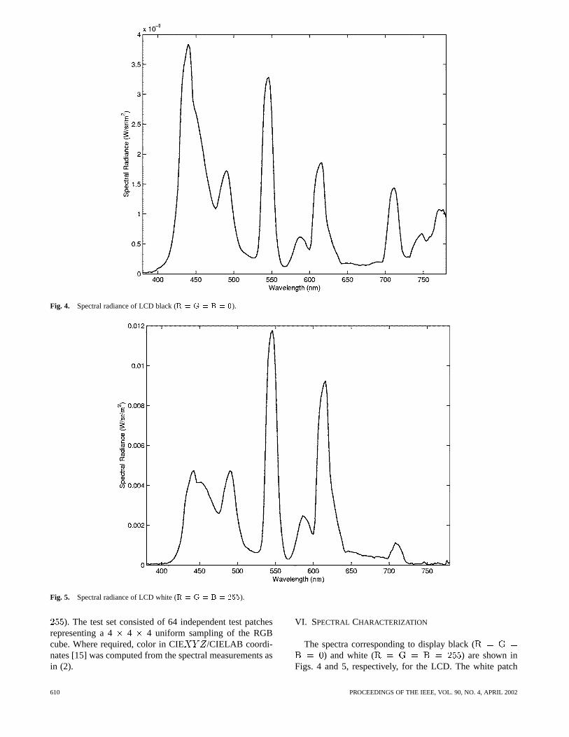
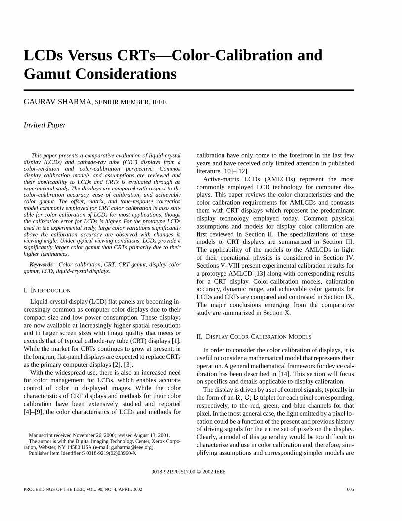
Fig. 4. Spectral radiance of LCD black (R = G = B = 0).
Fig. 5. Spectral radiance of LCD white (R = G = B = 255).
). The test set consisted of 64 independent test patchesrepresenting a 4 4 4 uniform sampling of the RGBcube. Where required, color in CIE /CIELAB coordi-nates [15] was computed from the spectral measurements asin (2).
VI. SPECTRAL CHARACTERIZATION
The spectra corresponding to display black () and white ( ) are shown in
Figs. 4 and 5, respectively, for the LCD. The white patch
610 PROCEEDINGS OF THE IEEE, VOL. 90, NO. 4, APRIL 2002
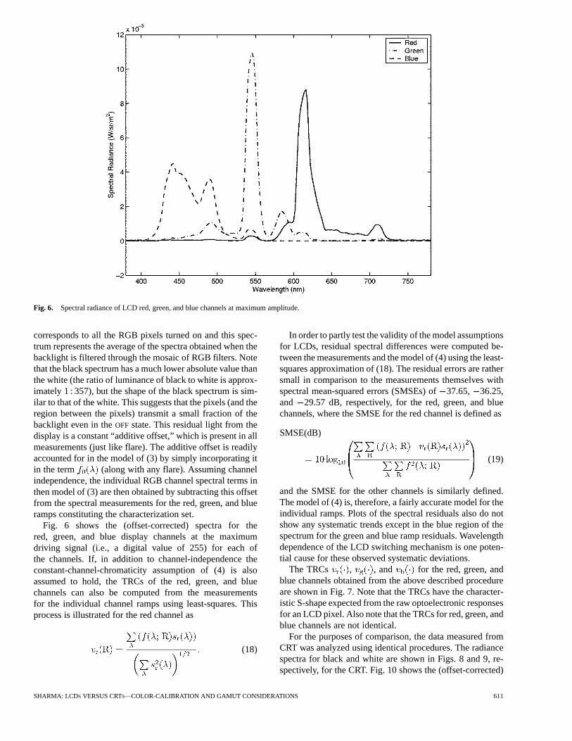
Fig. 6. Spectral radiance of LCD red, green, and blue channels at maximum amplitude.
corresponds to all the RGB pixels turned on and this spec-trum represents the average of the spectra obtained when thebacklight is filtered through the mosaic of RGB filters. Notethat the black spectrum has a much lower absolute value thanthe white (the ratio of luminance of black to white is approx-imately 1 : 357), but the shape of the black spectrum is sim-ilar to that of the white. This suggests that the pixels (and theregion between the pixels) transmit a small fraction of thebacklight even in theOFF state. This residual light from thedisplay is a constant “additive offset,” which is present in allmeasurements (just like flare). The additive offset is readilyaccounted for in the model of (3) by simply incorporating itin the term (along with any flare). Assuming channelindependence, the individual RGB channel spectral terms inthen model of (3) are then obtained by subtracting this offsetfrom the spectral measurements for the red, green, and blueramps constituting the characterization set.
Fig. 6 shows the (offset-corrected) spectra for thered, green, and blue display channels at the maximumdriving signal (i.e., a digital value of 255) for each ofthe channels. If, in addition to channel-independence theconstant-channel-chromaticity assumption of (4) is alsoassumed to hold, the TRCs of the red, green, and bluechannels can also be computed from the measurementsfor the individual channel ramps using least-squares. Thisprocess is illustrated for the red channel as
(18)
In order to partly test the validity of the model assumptionsfor LCDs, residual spectral differences were computed be-tween the measurements and the model of (4) using the least-squares approximation of (18). The residual errors are rathersmall in comparison to the measurements themselves withspectral mean-squared errors (SMSEs) of37.65, 36.25,and 29.57 dB, respectively, for the red, green, and bluechannels, where the SMSE for the red channel is defined as
SMSE(dB)
(19)
and the SMSE for the other channels is similarly defined.The model of (4) is, therefore, a fairly accurate model for theindividual ramps. Plots of the spectral residuals also do notshow any systematic trends except in the blue region of thespectrum for the green and blue ramp residuals. Wavelengthdependence of the LCD switching mechanism is one poten-tial cause for these observed systematic deviations.
The TRCs , , and for the red, green, andblue channels obtained from the above described procedureare shown in Fig. 7. Note that the TRCs have the character-istic S-shape expected from the raw optoelectronic responsesfor an LCD pixel. Also note that the TRCs for red, green, andblue channels are not identical.
For the purposes of comparison, the data measured fromCRT was analyzed using identical procedures. The radiancespectra for black and white are shown in Figs. 8 and 9, re-spectively, for the CRT. Fig. 10 shows the (offset-corrected)
SHARMA: LCDS VERSUS CRTS—COLOR-CALIBRATION AND GAMUT CONSIDERATIONS 611

Fig. 7. TRCs for the LCD red, green, and blue channels.
Fig. 8. Spectral radiance of CRT display black (R = G = B = 0).
spectra for the CRT red, green, and blue display channels atthe maximum driving signal (i.e., 255). Note that the CRTsradiances are significantly lower than the corresponding ra-diances for the LCD. Also, for the near-ideal setup used formeasurements (of a dark room with no flare), the spectrum
of the CRT black appears to be primarily measurement noisewith a very small contribution from the red phosphors, whichis evidenced by the two peaks in the black spectrum at thesame locations as the red channel. For these conditions, theblack offset may be ignored without significant loss of ac-
612 PROCEEDINGS OF THE IEEE, VOL. 90, NO. 4, APRIL 2002

Fig. 9. Spectral radiance of CRT display white (R = G = B = 0).
Fig. 10. Spectral radiance of CRT display red, green, and blue channels at maximum amplitude.
curacy, i.e., can be assumed in the model of(3). Under these ideal measurement conditions, the dynamicrange for the CRT, i.e., the ratio of white to black luminancesis approximately 4 351 : 1. By comparing Figs. 6 and 10, it
is clear that the spectral characteristics of LCDs and CRTsdiffer significantly. The LCD red and green channels haveunimodal spectral radiance distributions with fairly narrowspectral widths, whereas the CRT red-channel spectrum has
SHARMA: LCDS VERSUS CRTS—COLOR-CALIBRATION AND GAMUT CONSIDERATIONS 613

Fig. 11. TRCs for the CRT display red, green, and blue channels.
two narrow peaks and the green- and blue-channel spectraare fairly smooth with relatively large spectral widths.
The model of (4) using the least-squares approximation of(18) for the TRCs was also evaluated for the CRT. In thiscase, the SMSEs were38.30, 43.01, and 41.92 dB, re-spectively, for the red, green, and blue channels. The signifi-cantly smaller values of the SMSEs indicates that the modelof (4) models the behavior of CRTs to a greater degree ofaccuracy than LCDs. Plots of the model residual spectra arealso devoid of any systematic trends. The CRT TRCs for thered, green, and blue channels are shown in Fig. 11. The TRCsare in agreement with the power-law (gamma) relationshipof (15) (the best approximations for the gamma for the red,green, and blue channels were 2.34, 2.36, and 2.43, respec-tively). Compared to the LCD TRCs, the TRCs for the CRTRGB channels are fairly close to each other.
With the assumptions of channel-independence andchannel-chromaticity constancy, the per-channel spectralcharacterizations can be used with the model of (3) and (4)to predict the spectral radiance for the display correspondingto any RGB value. For both the LCD and the CRT display,predictions for the 64 independent test patches (representinga 4 4 4 uniform sampling of the RGB cube) were madeusing the TRCs determined in (18). These predictions werecompared with the actual measurements for the test patchesand SMSEs were evaluated. The SMSE for the LCD was
32.07 dB and for the CRT display the SMSE was37.14dB. Both values are quite small indicating that the modelpredictions provide close approximations to the measure-ments. The 5-dB lower value for the CRT SMSE indicatesthat the CRT measurements for the test patches are in betteragreement with the model than the LCD measurements, a
trend that was also observed in the per-channel case. Plotsof the spectral errors reinforce this observation: while theerrors for the CRT appear random, for the LCD the errorsare not completely random. The predominant trend is thepresence of mostly positive errors around the spectrumlocations corresponding to the three predominant peaks inthe white-patch spectrum.
VII. COLORIMETRIC CHARACTERIZATION
The measured characterization and test spectra and thespectral predictions obtained by using the models wereconverted to CIE tristimulus values [as indicated in(2)] from which CIELAB values were calculated usingthe respective display white measurements as the whitepoint. These CIELAB values were then used to computethe color errors in the characterization in [15] and
[32] units, which provide better agreement withthe perceived magnitude of the color error than SMSE ormean-squared error in tristimulus space [18], [32]. Theseerrors are tabulated in Table 1 for the LCD and in Table 2for the CRT display. Both tables report the errors over thecharacterization RGB ramps and the test patches separatelyand both the average and maximum color errors over eachof these data sets are tabulated.
For the CRT display, the color errors from the calibrationmodel are extremely small, with even the maximum colorerror under unit. This indicates that the model of(5)–(8) models the operation of the CRT remarkably well.For the LCD, the average color error over the test set is justaround 1.0 unit and the maximum errors is around 2.0
614 PROCEEDINGS OF THE IEEE, VOL. 90, NO. 4, APRIL 2002

Table 1LCD Color-Calibration Errors
Table 2CRT Display Color-Calibration Errors
Table 3Color-Calibration Errors for LCD and CRT Displays Over TestSamples With a “Gamma-Offset” TRC Model
. This level of error is acceptable for most imaging ap-plications and therefore the forward model of Fig. 1 and theinverse model of Fig. 2 can be applied for the color calibra-tion of LCDs, for all but the most critical imaging applica-tions.
Since several commercial image processing packagesallow for easy “gamma correction” of images, it is alsoworth determining how closely the power-law-basedmodel of (15) represents the display TRCs. For both theLCD and the CRT, the best “gamma” exponent and offsetvalues for each of the channels were determined through aleast-squares fit of the TRCs to (15). The power-law TRCscorresponding to the estimated gamma and offset valuesfrom (15) were then used in the forward model of (5)–(8) toobtain predicted tristimulus values for the test samples andcolor errors were computed as before. The resulting meanand maximum color errors in and units forthe LCD and the CRT display are reported in Table 3. Notethat the calibration errors for the CRT are only moderatelyhigher than the corresponding ones in Table 2. However, theerrors for the LCD are much larger than those in Table 1.Thus, the parametric model of (15) is clearly unsuitablefor representing the TRCs of LCDs and color-calibrationtechniques that rely on the parametric model for displaycalibration [33]–[35] should not be employed for LCDs.
The errors for the LCD characterization in Table 1 wereobtained based on the model of (5)–(8), which makes twofundamental assumptions: 1) channel independence, i.e.,the display RGB channels combine in a purely additivefashion, and 2) channel-chromaticity constancy, i.e., theLCD switching mechanism is wavelength independent(nondispersive). Since most LC materials exhibit somedispersion, the second assumption is the weaker of the
two assumptions. Furthermore, it is possible to drop thisassumption from the characterization process withoutrequiring additional characterization measurements (otherthan the ramps) by using the model of (3) directly.The model can be more conveniently implemented by con-sidering the corresponding version in terms of tristimulusvalues. CIE tristimulus values for each of the RGBchannels can be obtained from the measured values for thecorresponding ramps by interpolation of each tristimulusvalue and the channel-independence assumption can thenbe used to predict the CIE tristimulus values for anyarbitrary combination of RGB values. Using this method, a“forward model” for representing the operation of the LCDcan be obtained, as shown in Fig. 12. The model has nineindependent interpolation TRCs, three each correspondingto the values for each of the three RGB channels. Notethat the model can also be readily extended to a spectral onein a similar fashion.
The colorimetric errors obtained for the LCD with thisalternate “forward” model are given in Table 4. Note thatsince the model interpolates the measurements ob-tained from the characterization samples, the error over thecharacterization set is negligible. The error over the test sam-ples is also reduced in comparison to Table 1. However, theerrors are still significantly larger than those for the CRT.Note that while this alternate method of characterization re-quires no additional measurements, it cannot be directly in-verted to obtain an inverse model. Instead, the inversion mustbe done numerically and the transformation from CIEto device RGB requires a complete 3-D LUT instead of thesimple offset, matrix, and tone-response correction of Fig. 2.
VIII. A NGULAR DEPENDENCE OF THELCD DISPLAY
A common problem with most AMLCDs is one oflimited viewing angle. Due to the birefringent nature of LCmolecules, polarized light entering an LC material off axisis treated differently from polarized light entering alongthe optical axis (0 angle of incidence with respect to thenormal). The LC molecules are less effective in performingthe proper rotation for polarized light that enters the LCmaterial off axis. The electrooptic transfer function ofLCDs therefore tends to be angle dependent [31, p. 430]. Inaddition the LCs are dispersive and operate differently ondifferent wavelengths of light, especially when respondingto offaxis incident light. As one moves off axis (either upor down or from side to side), significant variations in hueand contrast occur with the change in viewing angle [36].As one moves far enough off axis, the contrast is diminishedto the point that it limits the useful viewing angle. Severalinnovative techniques have been developed to decreasethe viewing-angle dependence of LCDs [37]–[40], but thelimited useful viewing angle continues to be a significantlimitation of LCDs and further improvements in this areaare expected to continue.
In order to quantify the level of color shifts introduced byoffaxis viewing for the prototype LCD used in this paper,an additional set of measurements was made for the 64 test
SHARMA: LCDS VERSUS CRTS—COLOR-CALIBRATION AND GAMUT CONSIDERATIONS 615

Fig. 12. Graphical representation of the alternate forward model for LCD color calibration.
Table 4LCD Alternate “Forward Model” Color-Calibration Errors
patches along a viewing angle of approximately 30with re-spect to the normal to the display. Color differences betweenthe measurements for 0 and 30angles were computed in ab-solute (using the white measurement for 0as the white forconversion of both sets of measurements into CIELAB) andin relative (using measured white-point for each case as thewhite for conversion to CIELAB) CIELAB space. The meanand maximum color differences over the 64 test patches in
and units are given in Table 5. For both cases(absolute CIELAB and relative CIELAB), the color differ-ences are quite large and much larger than the color-calibra-tion errors of Section VII. The large magnitude of the dif-
Table 5Color Shifts Over Test Patches Between 0 and 30Viewingfor the LCD
ferences indicates that the LCD should only be used for alimited viewing angle if accurate color is desired.
The color shifts in relative CIELAB space for the 64 testpatches are shown in a 3-D plot in Fig. 13. The projectionsof the color shifts onto the plane are shown in Fig. 14.The lines in these plots represent the color shift with the dotsrepresenting the color seen along a 30viewing angle andthe other end representing the color that is seen along a 0viewing angle. Note that in it is clear that as the viewing anglechanges from 0 to 30, the colors move toward the centerof the and plane. Thus, the color shifts are such that
616 PROCEEDINGS OF THE IEEE, VOL. 90, NO. 4, APRIL 2002

Fig. 13. 3-D plot of color shifts in CIELAB for the LCD test patches for a change in viewing anglefrom 0 to 30 .
Fig. 14. Color shifts ina andb for the LCD test patches for a change in viewing angle from 0 to30 .
colors tend to desaturate as the viewing angle increases. Thepredominant effect seen in offaxis viewing is a reduction incontrast and saturation.
IX. COMPARISON OFLCD AND CRT DISPLAYS
The AMLCD technology has several advantages over theconventional CRT technology. LCDs have smaller size and
are less heavy and bulky than the CRTs, which is the drivingforce for their increasing use in portable and desktop de-vices. From an image-quality standpoint, the predominantand most clearly visible advantage is the higher spatial res-olution of the LCD devices, which translates into sharperimages. The color reproduction capabilities and achievablegamut for the LCD and CRT display are critically comparedin the remainder of this section.
SHARMA: LCDS VERSUS CRTS—COLOR-CALIBRATION AND GAMUT CONSIDERATIONS 617

1) Color Calibration: From the preceding sections, itis clear that LCDs and CRTs are similar in several respectsfrom the perspective of color calibration. Identical modelsbased on channel independence and channel-chromaticityconstancy can be used for the calibration of either typeof display and the runtime mapping of images to displaycolor coordinates can also be performed using the inversemodel of Fig. 2 in either case. For the CRT, these modelsprovide extremely good accuracy, whereas for LCDs,the accuracy is good enough for most applications. Forthe CRT, the use of parametric “gamma-offset” modelsfor the individual channel TRCs can further simplify thecharacterization process and potentially reduce the numberof measurements required. The S-shaped TRCs for LCDsare not modeled well by the parametric “gamma-offset”models and, therefore, additional measurements may berequired for the characterization of these devices. Forthe same reason, images that are “gamma-corrected” fordisplay on a CRT will not have the proper tone response ifdisplayed on an LCD, unless appropriate TRCs are used inhardware/software. Scientific applications involving veryprecise control of the displayed color require more elaboratecalibration schemes for the LCD. Note also that due to thesignificant difference in spectral characteristics of the CRTand LCDs, the impact of chromatic aberration in the eyewill be different for the two displays and may need to becompensated when displaying complex images for precisepsychophysical experiments [41].
2) Angular Dependence:CRTs are almost Lambertian[18] radiators within typical viewing angles [42], [43] andcan, therefore, be viewed over a wide range of viewingangles without loss of contrast or undesirable variationsin hue. While many improvements have been made inincreasing AMLCD viewing angles, the problem has notbeen completely eliminated and the useful viewing-anglerange of most LCDs is limited in comparison to CRTs. Thelimited viewing angle of LCDs is often a limitation whenprecisely color-corrected images are to be displayed beforean audience of more than one or two persons.
3) Spatial Homogeneity:LCDs significantly outperformCRTs with regard to spatial homogeneity. While there is neg-ligible variation in the color of a displayed pixel with changein the pixel’s position over the screen for an LCD [10], theassumption of spatial homogeneity does not strictly hold forCRTs. In most CRT monitors, for the same driving signals,the light intensity is brightest at the center and falls off towardthe edges. The change in luminance over the screen can be ashigh as 25% [7, p. 104]. In casual image display applications,this is not as objectionable as measurements would indicatebecause the eye’s sensitivity itself is not uniform over theentire field of view and because the eye adapts well to thesmooth variation in intensity across the screen. However, inscientific applications where precise control of the displayedcolor is required, it is necessary to correct for this spatial in-homogeneity in CRTs [44].
4) Luminance and Dynamic Range:For the displaysused in the experiment, the luminance of white on theLCD is about 4.7 times the luminance of white on the CRT
monitor. This difference is typical for most LCD and CRTdisplays [10]. For the measurements made in a completelydark room with almost no additive flare, the luminance ofblack on the LCD was about 58 times the luminance ofblack on the CRT and the dynamic range (ratio of whiteto black luminances) is around 357 : 1 for the LCD and4 351 : 1 for the CRT. On the face of it, the CRT appearsto have a larger dynamic range. However, in practice, theexact converse is true because a large region of the CRTsdynamic range is lost to additive flare under typical viewingconditions. In the presence of typical viewing flare, the ratioblack to white luminance for the CRT falls to 16 : 1, whereasthe corresponding ratio for the LCD remains significantlyhigher at 209 : 1. This reversal is owing to the fact that thetypical viewing flare has a much higher luminance thanthe CRT black in a dark room but is quite negligible ascompared to the light leakage through the LCD cells alreadypresent in the LCD black. The higher white luminance forthe LCDs gives them a higher effective dynamic range thantypical CRTs, which is clearly apparent in practice.
5) Intrinsic Gray Balance: It was observed in Sec-tion VI that individual red-, green–, and blue-channelTRCs of the CRT display were fairly close while thosefor the LCD were not. The difference between the LCDRGB TRCs would imply that a “device gray wedge”along would not appear visually neutral (graybalanced) when displayed on the LCD, but would appearalmost neutral when displayed on the CRT. This is actu-ally observed in practice. Since graphics programs oftencreate images or sweeps directly in display device colorspace, it is desirable to have the display gray-balancedand the CRTs characteristics are, therefore, preferable.Note, however, that this limitation of the LCD is easilyovercome once the display is calibrated and the inverseTRCs are incorporated into the video path.
6) Channel Chromaticities:Fig. 15 shows the locationof the channel chromaticities (the end points of the re-spective triangles) for the CRT and the LCD in relationto the spectrum locus on the CIE xy chromaticity diagram[16]–[18]. Note that the red channel chromaticity for theCRT and the LCD are fairly close to each other on thechromaticity diagram, but the blue and green channel chro-maticities are different from each other. Also plotted on thesame diagram are the chromaticities for the white point forthe CRT (labeled as letter C on the plot), the LCD (L), andthe CIE D50 and D65 daylight illuminants. Note that theLCD white point is somewhere between the D65 and D50white points, while the CRT white point is close to D65in chromaticity, which agrees with the selected 6500-Kcolor temperature for the CRT. The differences in whitepoint and in the channel chromaticities imply that the 3
3 color calibration matrices for the LCD and the CRTdisplay in the model of Fig. 2 are different. This impliesthat transformation of an image in CRT RGB coordinatesto LCD RGB coordinates requires full color correction andcannot be achieved by using 1-D corrections for each ofthe channels. While only one LCD was considered in theexperiment of this paper, this implication is probably true
618 PROCEEDINGS OF THE IEEE, VOL. 90, NO. 4, APRIL 2002

Fig. 15. Channel chromaticities for the LCD and CRT displays in relation to the spectrum locus. Alsoshown are the white-points C (CRT), L (LCD), 6 (CIE D65), and 5 (CIE D50).
in general because there are bound to be variations in LCDchannel chromaticities due to manufacturing tolerances inthe fabrication of the LCD filters and backlights.
7) Achievable Color Gamut:The triangle formed bythe three-channel chromaticity-coordinates for each displayin Fig. 15 represents the achievable gamut for the displayin chromaticity space. The 2-D representation is howeverrather limited and comparisons of the 3-D gamut in CIELABcoordinates using visualization tools [45] provide a muchmore complete and useful picture. Since the perception ofcolor is significantly influenced by the viewing conditions[46], three different gamut comparisons were performed,corresponding to different assumptions for the viewingconditions: 1) comparisons of ideal flareless “relative”gamuts, where each monitors own white point was usedas the nominal white-point [18, p. 167] in the conversionfrom CIE to CIELAB; 2) comparison of “relative”gamuts with typical flare; and 3) comparison of “absolute”gamuts, where flare is included and the CIE valuesfor the LCD white (having the higher luminance) wereused in the CIE to CIELAB conversion for both themeasurements from the LCD and the CRT. The first caserepresents the ideal achievable gamuts, assuming that thedisplays are viewed individually in a dark room and thatthe photopic response of the eye extends until the blackpoint of the CRT (which does not really hold). The secondcase corresponds to the more typical situation when the twodisplays are viewed individually at different times in typicalviewing environments. The third case is representative of thescenario when the two displays are viewed side by side at thesame time (the assumption here is that when the viewer sees
the two displays side by side, he/she adapts to the brighterwhite). For each of the three cases, the 3-D gamuts werecomputed in CIELAB space and visualized simultaneouslywith the larger gamut shown as a wire mesh and the smallergamut as a solid. Figs. 16–18 show perspective views of thegamuts for these different cases, where each figure includesa top view looking down on the gamuts from the axisand a side view, whose perspective position was chosen tohighlight the gamut differences.
For the flareless idealized gamuts of Fig. 16, the CRTgamut (wire frame) and the LCD gamut (solid) are fairlyclose in most color regions, except in the blue and magentaregions of color space, where the CRT gamut extends furtheroutwards covering a larger volume. The CRT gamut alsoextends further outward than the LCD gamut in the darkregions close to black. In the presence of typical viewingflare, however, the CRT not only loses its advantage overthe LCD, but also ends up with significantly smaller gamutin the dark regions. This can be seen from the gamut com-parisons of Fig. 17, where the LCD gamut (wire frame) issignificantly larger than the CRT gamut (solid), particularlyin the dark color regions around black. The dramatic increasein lightness ( ) value for the CRT black between Figs. 16and 17 is indicative of the significant reduction in dynamicrange caused by flare, which was mentioned earlier. Thesignificantly larger gamut in the dark color regions providesthe LCDs a significant advantage over CRTs when dis-playing images with large dynamic range and shadow detail.Fig. 18 presents a comparison of the LCD (wire frame) andCRT (solid) gamuts in “absolute” CIELAB (Case 3, above).The “absolute” CRT gamut is almost entirely contained
SHARMA: LCDS VERSUS CRTS—COLOR-CALIBRATION AND GAMUT CONSIDERATIONS 619
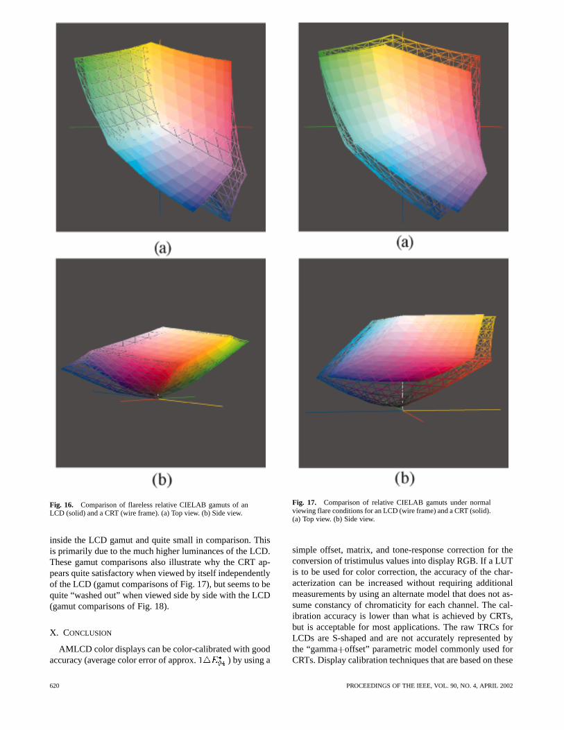
Fig. 16. Comparison of flareless relative CIELAB gamuts of anLCD (solid) and a CRT (wire frame). (a) Top view. (b) Side view.
inside the LCD gamut and quite small in comparison. Thisis primarily due to the much higher luminances of the LCD.These gamut comparisons also illustrate why the CRT ap-pears quite satisfactory when viewed by itself independentlyof the LCD (gamut comparisons of Fig. 17), but seems to bequite “washed out” when viewed side by side with the LCD(gamut comparisons of Fig. 18).
X. CONCLUSION
AMLCD color displays can be color-calibrated with goodaccuracy (average color error of approx. ) by using a
Fig. 17. Comparison of relative CIELAB gamuts under normalviewing flare conditions for an LCD (wire frame) and a CRT (solid).(a) Top view. (b) Side view.
simple offset, matrix, and tone-response correction for theconversion of tristimulus values into display RGB. If a LUTis to be used for color correction, the accuracy of the char-acterization can be increased without requiring additionalmeasurements by using an alternate model that does not as-sume constancy of chromaticity for each channel. The cal-ibration accuracy is lower than what is achieved by CRTs,but is acceptable for most applications. The raw TRCs forLCDs are S-shaped and are not accurately represented bythe “gamma offset” parametric model commonly used forCRTs. Display calibration techniques that are based on these
620 PROCEEDINGS OF THE IEEE, VOL. 90, NO. 4, APRIL 2002

Fig. 18. Comparison of “absolute” CIELAB gamuts of an LCD(wire frame) and a CRT (solid). (a) Top view. (b) Side view.
parametric models should not be directly applied to LCDcolor calibration.
The difference between the uncorrected TRCs forAMLCDs and CRTs implies that images designed forCRTs will not have the proper tone response on thesedisplays, unless appropriate tone-response corrections areused in hardware/software. The LCD channel-chromaticitycoordinates are determined by the backlight and color filterspectral characteristics, and may not correspond to thechromaticity coordinates for commonly employed CRTphosphors. Therefore, a simple per-channel 1-D correctioncannot be used to universally map CRT RGB to LCD RGB.
The prototype display studied in this paper showed astrong variation in color with change in viewing angle. Thisviewing-angle dependence limits the utility of the displayin accurate color demonstrations where the display is tobe simultaneously viewed by multiple observers. Whilesignificant viewing-angle improvements have been madein commercial displays [10], further improvements are stillneeded to match CRT viewing angles.
Typical AMLCDs possess a significantly larger gamutthan typical CRT displays, with the AMLCD gamut ex-tending significantly beyond CRT gamut in the dark colorregions. The differences in gamut arise primarily due tothe higher luminance of LCDs and provide AMLCDs asignificant advantage over CRTs in the reproduction ofimages with high dynamic range and shadow detail.
REFERENCES
[1] S. L. Wright, R. W. Nywening, S. E. Millman, J. Larimer, J.Gille, and J. Luszcz, “Image quality issues for height resolutionsTFTLCDs,” in Proc. IS&T/SID 7th Color Imaging Conf., Scotts-dale, AZ, Nov. 1999, pp. 100–105.
[2] J. A. Castellano, “Trends in the global CRT market,” inSID Int.Symp. Dig., May 1999, pp. 356–359.
[3] K. I. Werner, “The flat panel’s future,”IEEE Spectrum, vol. 30, pp.18–26, Nov. 1993.
[4] W. B. Cowan, “An inexpensive scheme for calibration of a colormonitor in terms of standard CIE coordinates,”Comput. Graphics,vol. 17, pp. 315–321, July 1983.
[5] W. B. Cowan and N. Rowell, “On the gun independency and phos-phor constancy of color video monitors,”Color Res. Appl., vol. 11,pp. S34–S38, 1986.
[6] D. H. Brainard, “Calibration of a computer controlled color mon-itor,” Color Res. Appl., vol. 14, no. 1, pp. 23–34, Feb. 1989.
[7] V. Mani, “Calibration of color monitors,” M. S. thesis, North Car-olina State University, Raleigh, NC, 1991.
[8] R. S. Berns, R. J. Motta, and M. E. Gorzynski, “CRT col-orimetry—Part I: Theory and practice,”Color Res. Appl., vol. 18,no. 5, pp. 299–314, Oct. 1993.
[9] R. S. Berns, M. E. Gorzynski, and R. J. Motta, “CRT col-orimetry—Part II: Metrology,”Color Res. Appl., vol. 18, no. 5, pp.315–325, Oct. 1993.
[10] M. D. Fairchild and D. Wyble, “Colorimetric characterization of theapple studio display (flat panel LCD),” Munsell Color Science Lab.,Rochester Institute of Technology, Rochester, NY, Tech. Rep., July1998.
[11] C. Y. Tsai, M. J. Shaw, and H. P. D. Shieh, “Color characterizationand reproduction of TN-LCDs,” inSID Int. Symp. Dig., May 1999,pp. 790–797.
[12] G. Sharma, “Color calibration of DPiX AMLCD display,” XeroxCorp., Webster, NY, Internal Memo, May 1999.
[13] R. Martin, J. Batey, T. Fiske, M. Nguyen, E. Rabner, D. Siemens,H. Steemers, S. Stuber, M. Thompson, W. Turner, M. Tilton, L. D.Silverstein, and M. Potts, “Design of high-resolution AMLCDs withgreater than 2000 gate lines,” inSID Int. Symp. Dig., May 1997, pp.7–10.
[14] M. J. Vrhel and H. J. Trussell, “Color device calibration: A math-ematical formulation,”IEEE Trans. Image Processing, vol. 8, pp.1796–1806, Dec. 1999.
[15] “Colorimetry,” Central Bureau of the CIE, Vienna, Austria, CIE Pub-lication No. 15.2, 1986.
[16] G. Sharma and H. J. Trussell, “Digital color imaging,”IEEE Trans.Image Processing, vol. 6, pp. 901–932, July 1997.
[17] G. Sharma, M. J. Vrhel, and H. J. Trussell, “Color imaging for mul-timedia,”Proc. IEEE, vol. 86, pp. 1088–1108, June 1998.
[18] G. Wyszecki and W. S. Stiles,Color Science: Concepts and Methods,Quantitative Data and Formulae, 2nd ed. New York: Wiley, 1982.
[19] C. D. Child, “Discharge from hot CaO,”Phys. Rev., vol. 32, no. 5,pp. 492–511, May 1911.
[20] I. Langmuir, “The effect of space charge and residual gases onthermionic current in high vacuum,”Phys. Rev., Second Series, vol.2, no. 6, pp. 450–486, Dec. 1913.
SHARMA: LCDS VERSUS CRTS—COLOR-CALIBRATION AND GAMUT CONSIDERATIONS 621
[21] B. M. Oliver, “Tone rendition in television,”Proc. IRE, vol. 38, pp.1288–1300, 1950.
[22] W. N. Sproson,Color Science in Television and Display Sys-tems. Bristol, U.K.: Adam Hilger, 1983.
[23] C. A. Poynton, “Gamma correction and tone reproduction in scannedphotographic images,”SMPTE J., vol. 103, pp. 377–385, June 1994.
[24] F. Kretz, “Subjectively optimal quantization of pictures,”IEEETrans. Commun., vol. COM-23, no. 11, pp. 1288–1292, Nov. 1975.
[25] J. M. Kasson and W. Plouffe, “An analysis of selected computer in-terchange color spaces,”ACM Trans. Graphics, vol. 11, no. 4, pp.373–405, Oct. 1992.
[26] C. A. Poynton, “‘Gamma’ and its disguises: The nonlinear mappingsof intensity in perception, CRTs, film, and video,”SMPTE J., vol.102, pp. 1099–1108, Dec. 1993.
[27] R. Patterson, “Gamma correction and tone reproduction in scannedphotographic images,”SMPTE J., vol. 103, pp. 377–385, June 1994.
[28] R. W. G. Hunt,The Reproduction of Color, 3rd ed. New York:Wiley, 1975.
[29] M. Anderson, R. Motta, S. Chandrasekar, and M. Stokes, “Proposalfor a standard default color space for the internet—sRGB,” inProc.IS&T/SID 4th Color Imaging Conf., Scottsdale, AZ, Nov. 1996, pp.238–246.
[30] M. A. Karim, Ed., Electro-Optical Displays. New York: MarcelDekker, 1992.
[31] L. E. Tannas, Ed.,Flat Panel Displays and CRTs. New York: VanNostrand Reinhold, 1985.
[32] , “Industrial color difference evaluation,” Central Bureau of the CIE,Vienna, Austria, CIE Publication No. 116-1995, 1995.
[33] R. J. Motta, “Visual characterization of color CRTs,”Proc. SPIE,vol. 1909, pp. 212–221, Feb. 1993.
[34] N. Katoh and T. Deguchi, “Reconsideration of the CRT monitorcharacteristics,” inProc. IS&T/SID 5th Color Imaging Conf., Scotts-dale, AZ, Nov. 1997, pp. 33–40.
[35] T. Deguchi, N. Katoh, and R. S. Berns, “Colorimetric characteri-zation of CRT monitors,” inSID Int. Symp. Dig., May 1999, pp.786–789.
[36] T. G. Fiske and L. D. Silverstein, “Characterizations of viewing-angle-dependent colorimetric and photometric performance of colorLCDs,” in SID Int. Symp. Dig., May 1999, pp. 565–568.
[37] S. Kaneko, Y. Hirai, and K. Sumiyoshi, “Wide-viewing angle im-provements for AMLCDs,” inSID Int. Symp. Dig., May 1999, pp.265–268.
[38] J. Pollack, “Sharp Microelectronics’ approach to new-generationAMLCDs,” Inform. Display, vol. 15, no. 2, pp. 16–20, Feb. 1999.
[39] C. Heinmüller, G. Haas, and P. M. Knoll, “Design of in-plane-com-pensation foils for viewing-angle enhancement,” inSID Int. Symp.Dig., May 1999, pp. 90–93.
[40] J. Chenand, K. C. Kang, J. DelPico, H. Seiberle, and M. Schadt,“Wide-viewing-angle photoaligned plastic films for TN-LCDs,,” inSID Int. Symp. Dig., May 1999, pp. 98–101.
[41] D. H. Marimont and B. A. Wandell, “Matching color images: Theimpact of axial chromatic aberration,”J. Opt. Soc. Amer. A, vol. 11,no. 12, pp. 3113–3122, Dec. 1994.
[42] J. Kalmer, Luminescent Screens: Photometry and Col-orimetry. London, U.K.: Iliffe, 1969.
[43] K. Kinameri, “Photometric error due to light emitting propertiesof color TV picture tubes,”J. Illum. Eng. Inst. Japan, vol. 67, pp.74–79, 1983.
[44] J. N. Cook, P. A. Sample, and R. N. Weinreb, “Solution to spatialinhomogenity on video monitors,”Color Res. Appl., vol. 18, no. 5,pp. 334–340, Oct. 1993.
[45] R. Rolleston, “Visualization of colorimetric calibration,”Proc.SPIE, vol. 1912, pp. 299–309, Feb. 1993.
[46] M. D. Fairchild, Color Appearance Models. Reading, MA: Ad-dison-Wesley, 1998.
[47] SID Int. Symp. Dig., May 1999.[48] SID Int. Symp. Dig., May 1993.
Gaurav Sharma (Senior Member, IEEE)received the B.E. degree in electronics andcommunication engineering from Universityof Roorkee, India, in 1990, the M.E. degreein electrical communication engineering fromthe Indian Institute of Science, Bangalore,India, in 1992, and the M.S. degree in appliedmathematics and the Ph.D. degree in electricaland computer engineering from North CarolinaState University (NCSU), Raleigh, in 1995 and1996, respectively.
From August 1992 through August 1996, he was a Research Assistantwith the Center for Advanced Computing and Communications in the Elec-trical and Computer Engineering Department, NCSU. Since August 1996,he has been a Member of the Research and Technical Staff with the XeroxCorporation’s Digital Imaging Technology Center, Webster, NY. He is alsoan Adjunct with the Electrical and Computer Engineering Departments atthe Rochester Institute of Technology, Rochester, NY. His current researchinterests include color science and imaging, signal restoration, image secu-rity and halftoning, and error correction coding.
Dr. Sharma is a Member of Sigma Xi, Phi Kappa Phi, Pi Mu Epsilon. He isthe Vice-President of the Rochester Chapter of the IEEE Signal ProcessingSociety.
622 PROCEEDINGS OF THE IEEE, VOL. 90, NO. 4, APRIL 2002