character lcds
DESCRIPTION
hereTRANSCRIPT

Character LCDsCreated by Ladyada
Last updated on 2013-07-26 02:45:29 PM EDT

2346889
101214171922
Guide Contents
Guide ContentsOverviewCharacter vs. Graphical LCDsLCD VarietiesWiring a Character LCD
Installing the Header PinsPower and BacklightContrast CircuitBus Wiring
Using a Character LCDMultiple Lines
RGB Backlit LCDsThe createChar Command
© AdafruitIndustries
http://learn.adafruit.com/character-lcds Page 2 of 22

Overview
We sell tons of lovely character LCDs for use with Arduino (http://adafru.it/aIS), they areextremely common and a fast way to have your project show status messages. This tutorial willshow how you can easily connect a character LCD, either 16x2 or 20x4 (http://adafru.it/198).
The LCDs we sell at Adafruit have a low power LED backlight, run on +5v and require only 6 datapins to talk to. You can use any data pins you want!
This tutorial will cover character LCDs carried at Adafruit - such as our "standard" blue&white16x2, RGB 16x2 LCDs, "standard" blue&white 20x4 and RGB 20x4 (http://adafru.it/aIT). We don'tguarantee it will work with any other LCDs. If you need help getting other LCDs to work, pleasecontact the place you purchased it from, they'll be happy to help!
© AdafruitIndustries
http://learn.adafruit.com/character-lcds Page 3 of 22
Character vs. Graphical LCDs
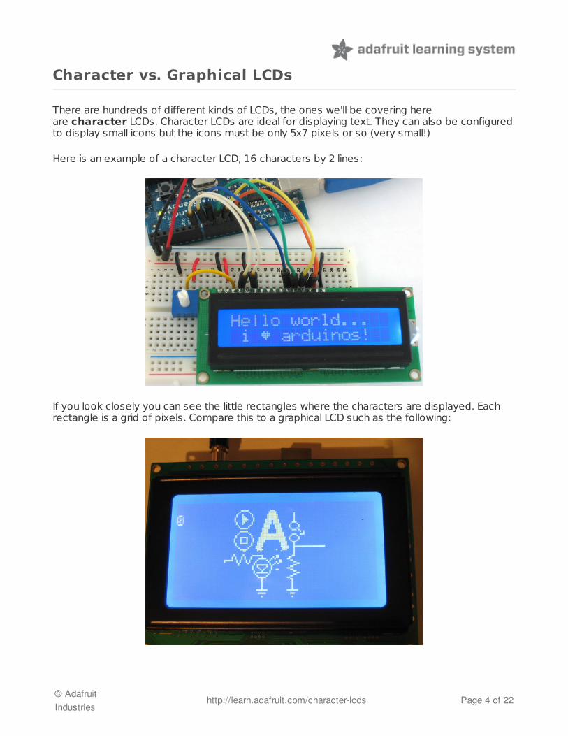
There are hundreds of different kinds of LCDs, the ones we'll be covering hereare character LCDs. Character LCDs are ideal for displaying text. They can also be configuredto display small icons but the icons must be only 5x7 pixels or so (very small!)
Here is an example of a character LCD, 16 characters by 2 lines:
If you look closely you can see the little rectangles where the characters are displayed. Eachrectangle is a grid of pixels. Compare this to a graphical LCD such as the following:
© AdafruitIndustries
http://learn.adafruit.com/character-lcds Page 4 of 22
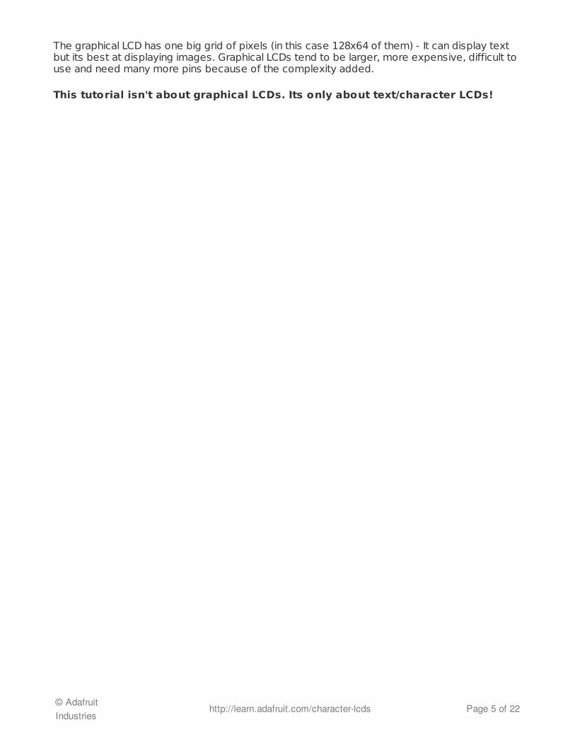
The graphical LCD has one big grid of pixels (in this case 128x64 of them) - It can display textbut its best at displaying images. Graphical LCDs tend to be larger, more expensive, difficult touse and need many more pins because of the complexity added.
This tutorial isn't about graphical LCDs. Its only about text/character LCDs!
© AdafruitIndustries
http://learn.adafruit.com/character-lcds Page 5 of 22

LCD Varieties
OK now that we're clear about what type of LCD we're talking about, its time to also look at thedifferent shapes they come in.
Although they display only text, they do come in many shapes: from top left we have a 20x4with white text on blue background, a 16x4 with black text on green, 16x2 with white text onblue and a 16x1 with black text on gray.
The good news is that all of these displays are 'swappable' - if you build your project with oneyou can unplug it and use another size. Your code may have to adjust to the larger size but atleast the wiring is the same!
For this part of the tutorial, we'll be using LCDs with a single strip of 16 pins as shown above.There are also some with 2 lines of 8 pins like so:
© AdafruitIndustries
http://learn.adafruit.com/character-lcds Page 6 of 22

These are much harder to breadboard. If you want some help in wiring these up, check out thispage (http://adafru.it/cl1).
© AdafruitIndustries
http://learn.adafruit.com/character-lcds Page 7 of 22

Wiring a Character LCD
Installing the Header Pins
OK now you've got your LCD, you'll also need a couple other things. First is a 10Kpotentiometer. This will let you adjust the contrast. Each LCD will have slightly different contrastsettings so you should try to get some sort of trimmer. You'll also need some 0.1" header - 16pins long.
If the header is too long, just cut/snap it short!
Next you'll need to solder the header to the LCD.You must do this, it is not OK to justtry to 'press fit' the LCD!
Also watch out not to apply too much heat, or you may melt the underlying breadboard. Youcan try 'tacking' pin 1 and pin 16 and then removing from the breadboard to finish the remainingsolder points
© AdafruitIndustries
http://learn.adafruit.com/character-lcds Page 8 of 22

The easiest way we know of doing this is sticking the header into a breadboard and then sittingthe LCD on top while soldering. this keeps it steady.
Power and Backlight
K now we're onto the interesting stuff!Get your LCD plugged into thebreadboard.
Now we'll provide power to thebreadboard. Connect +5V to the red rail,and Ground to the blue rail.
© AdafruitIndustries
http://learn.adafruit.com/character-lcds Page 9 of 22

Next we'll connect up the backlight forthe LCD. Connect pin 16 to ground andpin 15 to +5V. On the vast majority ofLCDs (including ones from Adafruit) theLCD includes a series resistor for the LEDbacklight.
If you happen to have one that does notinclude a resistor, you'll need to add onebetween 5V and pin 15. To calculate thevalue of the series resistor, look up themaximum backlight current and thetypical backlight voltage drop from thedata sheet. Subtract the voltage dropfrom 5 volts, then divide by the maximumcurrent, then round up to the nextstandard resistor value. For example, ifthe backlight voltage drop is 3.5v typicaland the rated current is 16mA, then theresistor should be (5 - 3.5)/0.016 = 93.75ohms, or 100 ohms when rounded up toa standard value. If you can't find the datasheet, then it should be safe to use a 220ohm resistor, although a value this highmay make the backlight rather dim.
Connect the Arduino up to power, you'llnotice the backlight lights up.
Note that some low-cost LCDs dont come with a backlight. Obviously in this case you shouldjust keep going.
Contrast Circuit
© AdafruitIndustries
http://learn.adafruit.com/character-lcds Page 10 of 22

Next, lets place the contrast pot, it goeson the side near pin 1.
Connect one side of the pot to +5V andthe other to Ground (it doesn't matterwhich goes on what side). The middle ofthe pot (wiper) connects to pin 3 of theLCD.
Now we'll wire up the logic of the LCD -this is seperate from the backlight! Pin 1is ground and pin 2 is +5V.
Now turn on the Arduino, you'll see thebacklight light up (if there is one), andyou can also twist the pot to see the firstline of rectangles appear.
© AdafruitIndustries
http://learn.adafruit.com/character-lcds Page 11 of 22

This means you've got the logic, backlight and contrast all worked out. Don't keep going unlessyou've got this figured out!
Bus WiringNow we'll finish up the wiring by connecting the data lines. There are 11 buslines: D0 through D7 (8 data lines) and RS, EN, and RW. D0-D7 are the pins that have the rawdata we send to the display. TheRS pin lets the microcontroller tell the LCD whether it wants todisplay that data (as in, an ASCII character) or whether it is a command byte (like, changeposistion of the cursor). The EN pin is the 'enable' line we use this to tell the LCD when data isready for reading. The RW pin is used to set the direction - whether we want to write to thedisplay (common) or read from it (less common)
The good news is that not all these pins are necessary for us to connect to the microcontroller(Arduino). RW for example, is not needed if we're only writing to the display (which is the mostcommon thing to do anyways) so we can 'tie' it to ground. There is also a way to talk to the LCDusing only 4 data pins instead of 8. This saves us 4 pins! Why would you ever want to use 8when you could use 4? We're not 100% sure but we think that in some cases its faster to use 8- it takes twice as long to use 4 - and that speed is important. For us, the speed isn't soimportant so we'll save some pins!
So to recap, we need 6 pins: RS, EN, D7, D6, D5, and D4 to talk to the LCD.
We'll be using the LiquidCrystal library to talk to the LCD so a lot of the annoying work ofsetting pins and such is taken care of. Another nice thing about this library is that you canuse any Arduino pin to connect to the LCD pins. So after you go through this guide, you'll find iteasy to swap around the pins if necessary
As mentioned, we'll not be usingthe RW pin, so we can tie it go ground.That's pin 5 as shown here.
Next is the RS pin #4. We'll use a brownwire to connect it to Arduino's digital pin#7.
© AdafruitIndustries
http://learn.adafruit.com/character-lcds Page 12 of 22

Next is the EN pin #6, we'll use a whitewire to connect it to Arduino digital #8.
Now we will wire up the data pins. DB7 ispin #14 on the LCD, and it connects withan orange wire to Arduino #12.
Next are the remaining 3 datalines, DB6 (pin #13 yellow) DB5 (pin#12 green) and DB4 (pin #11 blue)which we connect to Arduino #11,10 and 9.
You should have four 'gap' pinson the LCD between the 4 databus wires and the control wires.
This is what you'll have on your desk.
© AdafruitIndustries
http://learn.adafruit.com/character-lcds Page 13 of 22
Using a Character LCD
Now we must upload some sketch to the Arduino to talk to the LCD. Luckilythe LiquidCrystal library is already built in. So we just need to load one of the examples andmodify it for the pins we used.
If you've changed the pins, you'll want to make a handy table so you can update the sketchproperly.
LCD pin name RS EN DB4 DB5 DB6 DB7
Arduino pin # 7 8 9 10 11 12
Open up the File®®Examples®®LiquidCrystal®®HelloWorld example sketch
Now we'll need to update the pins. Look for this line:
And change it to:
To match the pin table we just made.
Now you can compile and upload the sketch.
LiquidCrystal lcd(12, 11, 5, 4, 3, 2);
LiquidCrystal lcd(7, 8, 9, 10, 11, 12);
© AdafruitIndustries
http://learn.adafruit.com/character-lcds Page 14 of 22

Adjust the contrast if necessary
You can of course use any size or color LCD, such as a 20x4 LCD
© AdafruitIndustries
http://learn.adafruit.com/character-lcds Page 15 of 22

Or a black on green
The nice thing about the black on green ones is you can remove the backlight. Sometimes theydont come with one!
© AdafruitIndustries
http://learn.adafruit.com/character-lcds Page 16 of 22

Multiple LinesOne thing you'll want to watch for is how the LCD handles large messages and multiple lines. Forexample if you changed this line:
To this:
The 16x2 LCD will cut off anything past the 16th character:
lcd.print("hello, world!");
lcd.print("hello, world! this is a long long message");
© AdafruitIndustries
http://learn.adafruit.com/character-lcds Page 17 of 22
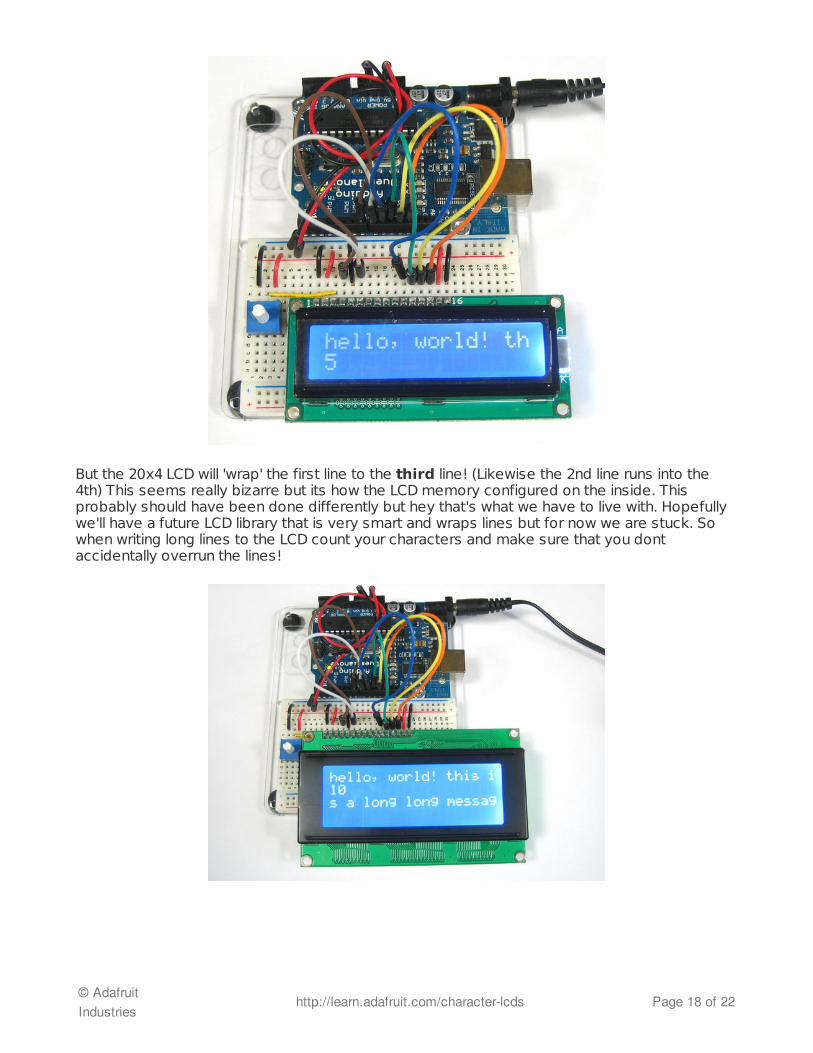
But the 20x4 LCD will 'wrap' the first line to the third line! (Likewise the 2nd line runs into the4th) This seems really bizarre but its how the LCD memory configured on the inside. Thisprobably should have been done differently but hey that's what we have to live with. Hopefullywe'll have a future LCD library that is very smart and wraps lines but for now we are stuck. Sowhen writing long lines to the LCD count your characters and make sure that you dontaccidentally overrun the lines!
© AdafruitIndustries
http://learn.adafruit.com/character-lcds Page 18 of 22
RGB Backlit LCDs
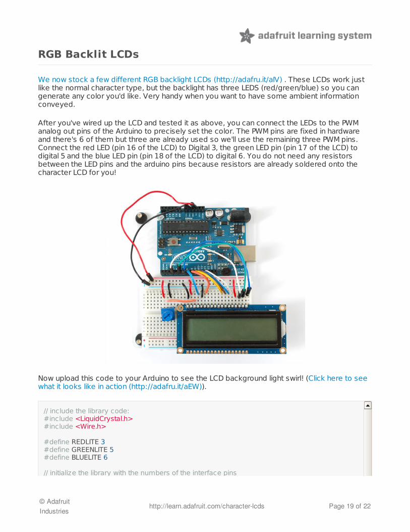
We now stock a few different RGB backlight LCDs (http://adafru.it/aIV) . These LCDs work justlike the normal character type, but the backlight has three LEDS (red/green/blue) so you cangenerate any color you'd like. Very handy when you want to have some ambient informationconveyed.
After you've wired up the LCD and tested it as above, you can connect the LEDs to the PWManalog out pins of the Arduino to precisely set the color. The PWM pins are fixed in hardwareand there's 6 of them but three are already used so we'll use the remaining three PWM pins.Connect the red LED (pin 16 of the LCD) to Digital 3, the green LED pin (pin 17 of the LCD) todigital 5 and the blue LED pin (pin 18 of the LCD) to digital 6. You do not need any resistorsbetween the LED pins and the arduino pins because resistors are already soldered onto thecharacter LCD for you!
Now upload this code to your Arduino to see the LCD background light swirl! (Click here to seewhat it looks like in action (http://adafru.it/aEW)).
// include the library code:#include <LiquidCrystal.h>#include <Wire.h> #define REDLITE 3#define GREENLITE 5#define BLUELITE 6 // initialize the library with the numbers of the interface pins
© AdafruitIndustries
http://learn.adafruit.com/character-lcds Page 19 of 22

// initialize the library with the numbers of the interface pinsLiquidCrystal lcd(7, 8, 9, 10, 11, 12); // you can change the overall brightness by range 0 -> 255int brightness = 255; void setup() { // set up the LCD's number of rows and columns: lcd.begin(16, 2); // Print a message to the LCD. lcd.print("RGB 16x2 Display "); lcd.setCursor(0,1); lcd.print(" Multicolor LCD "); pinMode(REDLITE, OUTPUT); pinMode(GREENLITE, OUTPUT); pinMode(BLUELITE, OUTPUT);
brightness = 100;} void loop() { for (int i = 0; i < 255; i++) { setBacklight(i, 0, 255-i); delay(5); } for (int i = 0; i < 255; i++) { setBacklight(255-i, i, 0); delay(5); } for (int i = 0; i < 255; i++) { setBacklight(0, 255-i, i); delay(5); }} void setBacklight(uint8_t r, uint8_t g, uint8_t b) { // normalize the red LED - its brighter than the rest! r = map(r, 0, 255, 0, 100); g = map(g, 0, 255, 0, 150); r = map(r, 0, 255, 0, brightness); g = map(g, 0, 255, 0, brightness); b = map(b, 0, 255, 0, brightness); // common anode so invert! r = map(r, 0, 255, 255, 0); g = map(g, 0, 255, 255, 0); b = map(b, 0, 255, 255, 0); Serial.print("R = "); Serial.print(r, DEC); Serial.print(" G = "); Serial.print(g, DEC); Serial.print(" B = "); Serial.println(b, DEC); analogWrite(REDLITE, r); analogWrite(GREENLITE, g); analogWrite(BLUELITE, b);}
© AdafruitIndustries
http://learn.adafruit.com/character-lcds Page 20 of 22

© AdafruitIndustries
http://learn.adafruit.com/character-lcds Page 21 of 22
The createChar Command
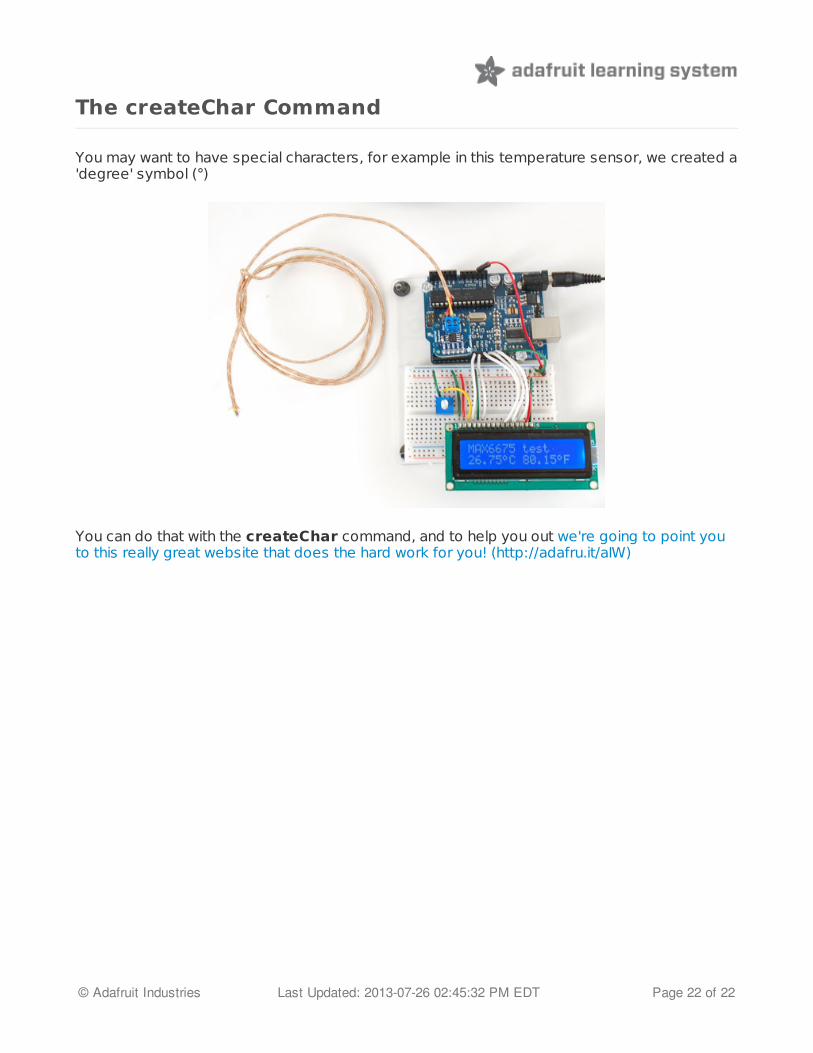
You may want to have special characters, for example in this temperature sensor, we created a'degree' symbol (°)
You can do that with the createChar command, and to help you out we're going to point youto this really great website that does the hard work for you! (http://adafru.it/aIW)
© Adafruit Industries Last Updated: 2013-07-26 02:45:32 PM EDT Page 22 of 22