lcd module product specificationlcd module int018atft version: 1.0 3 2. introduction int018atft is...
TRANSCRIPT
Website: www.displaytech.com.hk
LCD Module Product Specification
Product: INT018ATFT
1.8'' Integrated TFT Display Module (128RGBx160DOTS)
Contents in this document are subject to change without notice. No part of this document may be reproduced or transmitted in any form or by any means, electronic or mechanical, for any purpose, without the express written permission of Displaytech Ltd.
1 April 2011.
Displaytech Ltd LCD MODULE INT018ATFT Version: 1.0
1
1. REVISION RECORD VERSION CHANGES DATE
1.0 Initial revision 1 April 2011

Displaytech Ltd LCD MODULE INT018ATFT Version: 1.0
2
Table of Content
1. REVISION RECORD .......................................................................... 1
2. Introduction .......................................................................................... 3
3. Features ................................................................................................. 3
4. General Specifications .......................................................................... 4
5. Mechanical Drawing ............................................................................. 5
6. Interface Description ............................................................................ 6
7. Absolute Maximum Ratings ................................................................ 7
8. Electrical Characteristics ..................................................................... 7
9. Display Controller /Power Supply Timing ......................................... 7
10. Backlight specification ......................................................................... 8
11. Optical Characteristics ......................................................................... 8
12. Safety Precaution ................................................................................ 11
Displaytech Ltd LCD MODULE INT018ATFT Version: 1.0
3
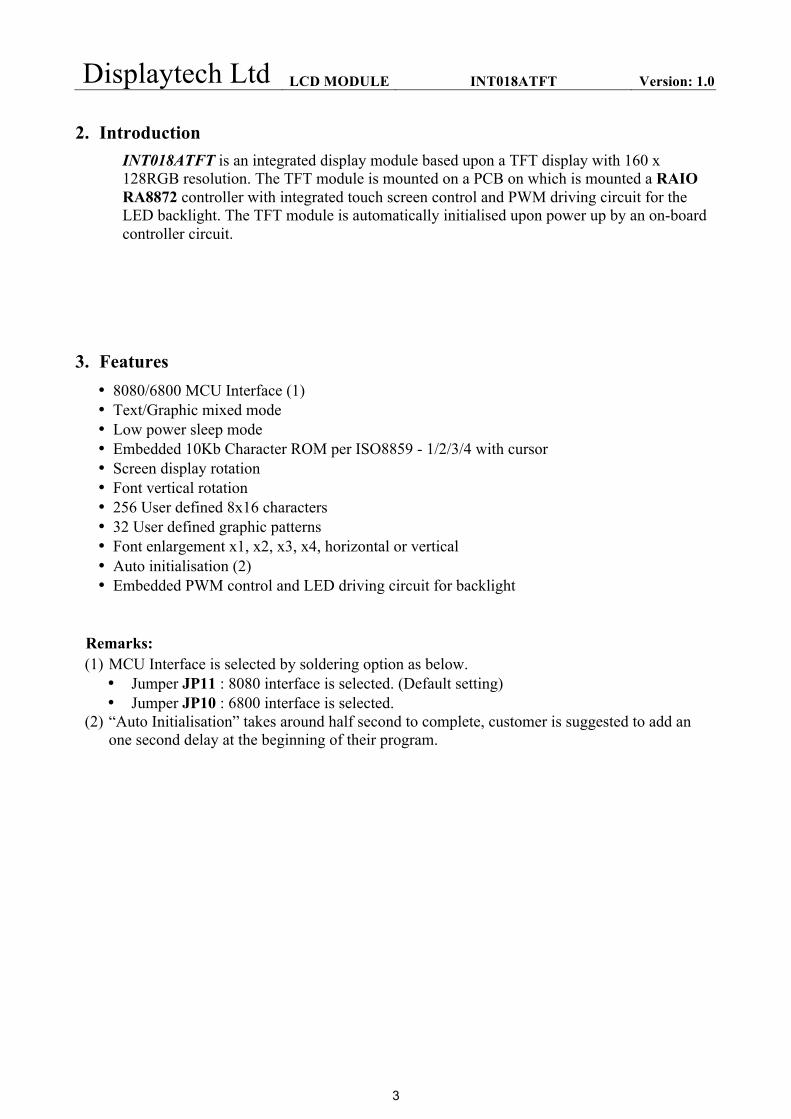
2. Introduction INT018ATFT is an integrated display module based upon a TFT display with 160 x 128RGB resolution. The TFT module is mounted on a PCB on which is mounted a RAIO RA8872 controller with integrated touch screen control and PWM driving circuit for the LED backlight. The TFT module is automatically initialised upon power up by an on-board controller circuit.
3. Features • 8080/6800 MCU Interface (1) • Text/Graphic mixed mode • Low power sleep mode • Embedded 10Kb Character ROM per ISO8859 - 1/2/3/4 with cursor • Screen display rotation • Font vertical rotation • 256 User defined 8x16 characters • 32 User defined graphic patterns • Font enlargement x1, x2, x3, x4, horizontal or vertical • Auto initialisation (2) • Embedded PWM control and LED driving circuit for backlight
Remarks: (1) MCU Interface is selected by soldering option as below.
• Jumper JP11 : 8080 interface is selected. (Default setting) • Jumper JP10 : 6800 interface is selected.
(2) “Auto Initialisation” takes around half second to complete, customer is suggested to add an one second delay at the beginning of their program.

Displaytech Ltd LCD MODULE INT018ATFT Version: 1.0
4
4. General Specifications Item Specification Unit
LCD mode Transmissive ---
Resolution 128(RGB) Line
160 Line Diagonal Size 1.8 Inch
Overall Size 60.00 mm 61.50 mm
Active area 28.03 mm 35.04 mm
Optimum Viewing Direction 6 o’clock --- Controller IC RA8872 ---
Interface type 8080/6800 with 8 Data Bus Width (1) ---
Colours 65K --- Operation temperature range -20~70 °C Storage temperature range -30~80 °C
Remarks: (1) MCU Interface is selected by soldering option as below.
• Jumper JP11 : 8080 interface is selected. (Default setting) • Jumper JP10 : 6800 interface is selected.
(2) Color tune may be changed slightly by temperature and driving voltage. (3) RoHS compliant. Component Life Cycle 1) Storage Life: min. 1 Year 2) Operation Life (*1): min. 43 x 10³ h (24hr/day x 7days/week x 52weeks/year x 5years) (Not include backlight) 3) Storage and Operation Life Times are defined for a temperature of +25°C Notes: *1. Operation life ends when one of the listed faults occurs:
The on/off response-times reach 1.5 times of the max. value specified for a new display
The contrast is reduced to 0.5 of the original contrast value Loss of function The number of cosmetic defects exceeds the maximum defined

Displaytech Ltd LCD MODULE INT018ATFT Version: 1.0
5
5. Mechanical Drawing • INT018ATFT
Displaytech Ltd LCD MODULE INT018ATFT Version: 1.0
6
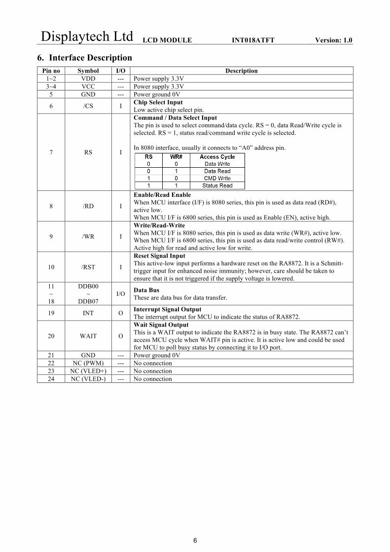
6. Interface Description Pin no Symbol I/O Description
1~2 VDD --- Power supply 3.3V 3~4 VCC --- Power supply 3.3V
5 GND --- Power ground 0V
6 /CS I Chip Select Input Low active chip select pin.
7 RS I
Command / Data Select Input The pin is used to select command/data cycle. RS = 0, data Read/Write cycle is selected. RS = 1, status read/command write cycle is selected. In 8080 interface, usually it connects to “A0” address pin.
8 /RD I
Enable/Read Enable When MCU interface (I/F) is 8080 series, this pin is used as data read (RD#), active low. When MCU I/F is 6800 series, this pin is used as Enable (EN), active high.
9 /WR I
Write/Read-Write When MCU I/F is 8080 series, this pin is used as data write (WR#), active low. When MCU I/F is 6800 series, this pin is used as data read/write control (RW#). Active high for read and active low for write.
10 /RST I
Reset Signal Input This active-low input performs a hardware reset on the RA8872. It is a Schmitt-trigger input for enhanced noise immunity; however, care should be taken to ensure that it is not triggered if the supply voltage is lowered.
11 ~ 18
DDB00 ~
DDB07 I/O Data Bus
These are data bus for data transfer.
19 INT O Interrupt Signal Output The interrupt output for MCU to indicate the status of RA8872.
20 WAIT O
Wait Signal Output This is a WAIT output to indicate the RA8872 is in busy state. The RA8872 can’t access MCU cycle when WAIT# pin is active. It is active low and could be used for MCU to poll busy status by connecting it to I/O port.
21 GND --- Power ground 0V 22 NC (PWM) --- No connection 23 NC (VLED+) --- No connection 24 NC (VLED-) --- No connection
Displaytech Ltd LCD MODULE INT018ATFT Version: 1.0
7
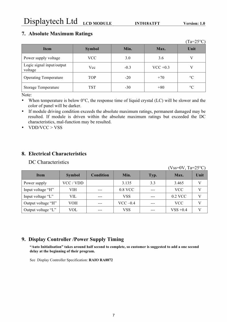
7. Absolute Maximum Ratings (Ta=25°C)
Item Symbol Min. Max. Unit
Power supply voltage VCC 3.0 3.6 V
Logic signal input/output voltage Vcc -0.3 VCC +0.3 V
Operating Temperature TOP -20 +70 °C
Storage Temperature TST -30 +80 °C
Note: • When temperature is below 0°C, the response time of liquid crystal (LC) will be slower and the
color of panel will be darker. • If module driving condition exceeds the absolute maximum ratings, permanent damaged may be
resulted. If module is driven within the absolute maximum ratings but exceeded the DC characteristics, mal-function may be resulted.
• VDD/VCC > VSS
8. Electrical Characteristics DC Characteristics
(Vss=0V, Ta=25°C) Item Symbol Condition Min. Typ. Max. Unit
Power supply VCC / VDD 3.135 3.3 3.465 V Input voltage “H” VIH --- 0.8 VCC --- VCC V Input voltage “L” VIL --- VSS --- 0.2 VCC V Output voltage “H” VOH --- VCC –0.4 --- VCC V Output voltage “L” VOL --- VSS --- VSS +0.4 V
9. Display Controller /Power Supply Timing “Auto Initialisation” takes around half second to complete, so customer is suggested to add a one second delay at the beginning of their program. See Display Controller Specification: RAIO RA8872

Displaytech Ltd LCD MODULE INT018ATFT Version: 1.0
8
10. Backlight specification (Vcc=3.3V, Vss=0V, Ta=25°C)
Item Symbol Condition Min Typ Max Unit Note Supply voltage Vf If=20mA x2 2.9 --- 3.5 V 2 Forward current If --- 40 --- mA 3 Uniformity ΔBp
If=30mA 80 --- --- %
Color coordination X 0.260 --- 0.305 --- Y 0.265 --- 0.305 ---
LED circuit diagram:
Constant current If=20x2mA; Vf=3.2±0.3V(typ) Note:
1) As there has built-in PWM control for the backlight, so the backlight driving specification is only applicable for direct driving.
2) The LED’s driver mode needs to be constant current mode. 3) Permanent damage to the device may occur if maximum values are exceeded. Functional operation should be
restricted to the conditions described under normal operating conditions.
11. Optical Characteristics (Vcc=3.3V, Vss=0V, Ta=25°C)
Item Symbol Condition Min Typ Max Unit Note Brightness Bp θ=0º
Ф=0º 250 280 --- cd/m² 1
Uniformity ΔBp 80 --- --- % 1, 2
Viewing Angle
θ1 (Ф=90° or 270°)
Cr≥10
-65 ~ 65
deg 3 θ2 (Ф=0°
or 180°)
-50 ~ 40
Contrast ratio Cr θ=0º Ф=0º
--- 350 --- --- 4
Response Time Tr --- 30 --- ms 5 Tf
CIE
(x,y
) C
hrom
atic
ity White x
θ=0º Ф=0º
0.2451 0.2951 0.3451
--- 1, 6
y 0.2664 0.3164 0.3664
Red x 0.5333 0.5833 0.6333 y 0.2804 0.3304 0.3804
Green x 0.2913 0.3413 0.3913 y 0.5314 0.5814 0.6314
Blue x 0.1036 0.1536 0.2036 y 0.0465 0.0965 0.1465
NTSC Ratio S --- 51 --- %
Displaytech Ltd LCD MODULE INT018ATFT Version: 1.0
9
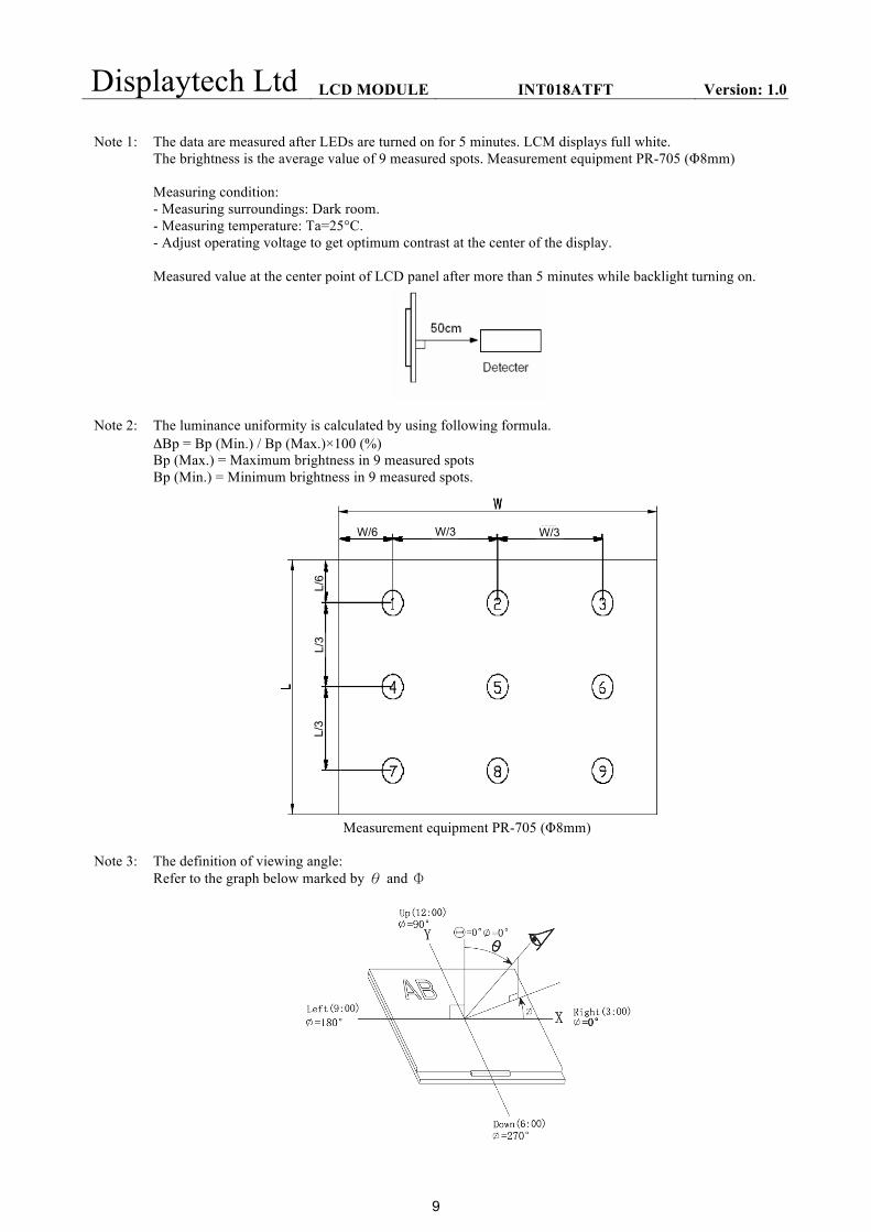
Note 1: The data are measured after LEDs are turned on for 5 minutes. LCM displays full white.
The brightness is the average value of 9 measured spots. Measurement equipment PR-705 (Φ8mm) Measuring condition: - Measuring surroundings: Dark room. - Measuring temperature: Ta=25°C. - Adjust operating voltage to get optimum contrast at the center of the display. Measured value at the center point of LCD panel after more than 5 minutes while backlight turning on.
Note 2: The luminance uniformity is calculated by using following formula. ΔBp = Bp (Min.) / Bp (Max.)×100 (%) Bp (Max.) = Maximum brightness in 9 measured spots Bp (Min.) = Minimum brightness in 9 measured spots.
Measurement equipment PR-705 (Φ8mm)
Note 3: The definition of viewing angle: Refer to the graph below marked by θ and Ф
W/6 W/3 W/3
L/6
L/3
L/3
Displaytech Ltd LCD MODULE INT018ATFT Version: 1.0
10
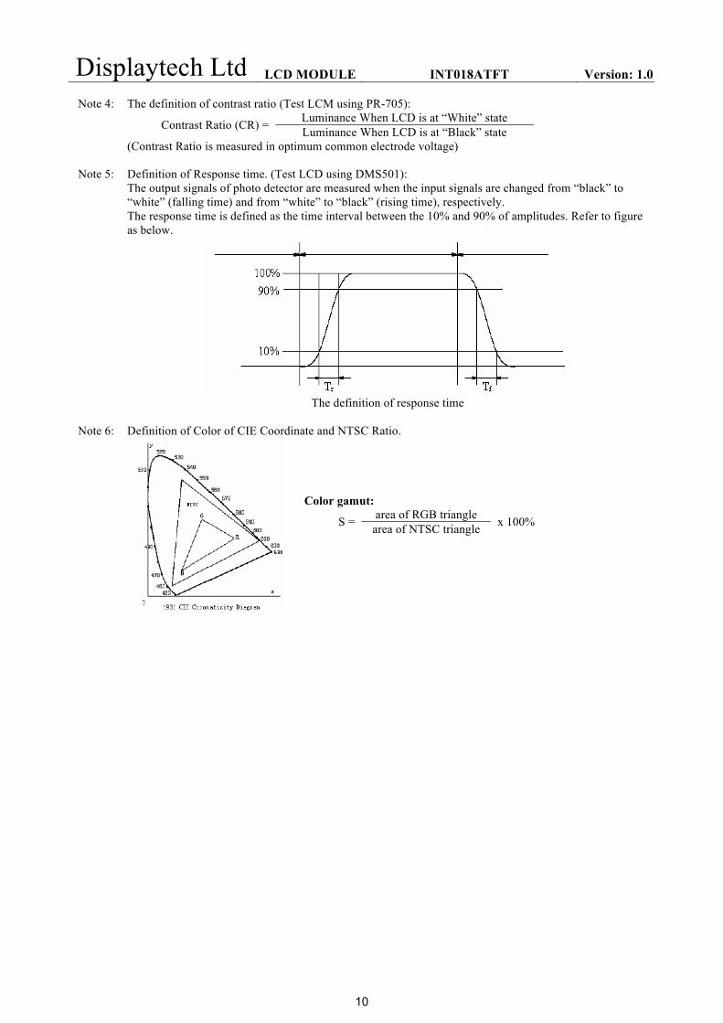
Note 4: The definition of contrast ratio (Test LCM using PR-705):
Contrast Ratio (CR) = Luminance When LCD is at “White” state Luminance When LCD is at “Black” state
(Contrast Ratio is measured in optimum common electrode voltage)
Note 5: Definition of Response time. (Test LCD using DMS501): The output signals of photo detector are measured when the input signals are changed from “black” to “white” (falling time) and from “white” to “black” (rising time), respectively. The response time is defined as the time interval between the 10% and 90% of amplitudes. Refer to figure as below.
The definition of response time
Note 6: Definition of Color of CIE Coordinate and NTSC Ratio.
Color gamut:
S = area of RGB triangle x 100% area of NTSC triangle
Displaytech Ltd LCD MODULE INT018ATFT Version: 1.0
11
12. Safety Precaution
Handling precautions:
• This device is susceptible to Electro-Static Discharge (ESD) damage. Observe Anti-Static precautions.
Power supply precautions:
• Identify and, at all times, observe absolute maximum ratings for both logic and LC drivers. Note that there is some variance between models.
• Prevent the application of reverse polarity to VCC and GND, however briefly.
• Use a clean power source free from transients. Power up conditions are occasionally “jolting” and may exceed the maximum ratings of the modules.
• The VCC power of the module should also supply the power to all devices that may access the display. Don’t allow the data bus to be driven when the logic supply to the module is turned off.
Operating precautions:
• DO NOT plug or unplug the module when the system is powered up.
• Minimize the cable length between the module and host MPU.
• Operate the module within the limits of the modules temperature specifications.
Mechanical/Environmental precautions:
• Improper soldering is the major cause of module difficulty. Use of flux cleaner is not recommended.
• Mount the module so that it is free from torque and mechanical stress.
• Surface of the LCD panel should not be touched or scratched. The display front surface is an easily scratched, plastic polarizer. Avoid contact and clean only when necessary with soft, absorbent cotton dampened with petroleum benzene.
• Always employ anti-static procedure while handling the module.
• Prevent moisture build-up upon the module and observe the environmental constraints for storage temperature and humidity.
• Do not store in direct sunlight
• If leakage of the liquid crystal material should occur, avoid contact with this material, particularly ingestion. If the body or clothing becomes contaminated by the liquid crystal material, wash thoroughly with water and soap