project1.qxd:layout 1 11/12/09 2:33 pm page 1 dl series zif... · 2020. 12. 1. ·...
TRANSCRIPT

Project1.qxd:Layout 1 11/12/09 2:33 PM Page 1

www.ittcannon.com
Cannon, VEAM, BIW
A Historical Achievement of Technology Leadership
Defining and Championing Innovation
Showcasing a portfolio of creativity, ITT’s “Engineered For Life” execution embraces products which havebecome ubiquitous in a broad collection of markets including: Military/Aerospace, Civil Aircraft, IndustrialInstrumentation, Medical, Oil & Gas, Energy, Transportation, Telecom/Handset, Computer, Consumer, andAutomotive.
ITT’s rich interconnect history embraces contributions to both technological breakthroughs and social move-ments. With one of the industry’s broadest product offerings, ITT’s interconnect products have supported:
• Every Free World space mission, bringing the universe to our doorstep.
• Motion picture, radio, and television equipment, serving laughter and entertainment to millions.
• Commercial and military communications systems, linking the voices of the world.
• Computerized tools, reshaping the information highway.
• Aircraft, rapid transit, and automobiles, mobilizing our expanding society.
• Oil and natural gas production, powering the world’s economies.
• Agricultural equipment, attacking the roots of world hunger.
Project1.qxd:Layout 1 11/12/09 2:33 PM Page 2

ITT Interconnect Solutions
ITT Interconnect Solutions is a division of the multi-national ITT Corporation, a $9 billion dollar globalenterprise representing the brands Cannon, VEAM,and BIW. Our connector portfolio remains the mostextensive in the industry offering the most reliable andcost effective range of interconnect solutions. Theseinnovations have enabled ITT to provide products andtechnologies to such markets as:
• Automotive• Computer/Consumer• Industrial/Instrumentation• Military/Aerospace• Oil Fields• Telecom/Handset• Transportation
When you specify a Cannon, VEAM or BIW connector,you can rely on a product designed, developed, andmanufactured to the highest quality and reliabilitystandards. This tradition of excellence is based on ITT’scorporate culture of operating its businesses under theprinciples of Six Sigma. At ITT, Six Sigmais not just a quality philosophy but a completecorporate culture that drives the entire business. OurValue Based Management and Value Based ProductDevelopment systems are two cornerstones that allowfor the development of both leadership and productengineering principles, ensuring the correct industryleading products are developed to the acceptedmarket driven lead times. These principles haveallowed ITT to become the market leader in all of ourbusiness portfolios.
Six Sigma Manufacturing
ITT operates manufacturing facilities in the UnitedStates, Germany, Italy, Mexico, China, Japan and theUK, all of which have particular product area strengthsallowing ITT to offer a truly global footprint to ourcustomers. Our facilities are world class and accom-modate full vertical integration utilizing the latestmanufacturing technologies including: automated androbotic machining centers, Super Market manufactur-ing cells, Kanban pull systems, and automated electri-cal, mechanical, and optical test and inspection equip-ment. The combination of our manufacturing strengthand our advanced manufacturing facilities allows ITT
to offer products at market driven prices. Our capabili-ties, especially in robotics, computerized precision tool-ing, Kaizen Project Management, Six Sigma tools, andtesting, give ITT the most optimized global manufac-turing footprint in the interconnect industry.
The Custom Difference
As the industry leader in harsh environment intercon-nect applications, ITT’s world class engineering teamswill work directly with our customers to design anddevelop cost effective solutions for their applications.In many cases we may modify one of our standarddesigns to ensure a highly reliable solution wheretiming is critical. Yet, in those cases where a completecustom interconnect solution is required, ITT will workwith our customer’s Engineers to design an intercon-nect solution which will be cost effective yet highlyreliable. As professional consultants, our Engineeringteams will provide a thorough systems and mechani-cal analysis of any proposed solution. These analysesprovide our customers with sophisticated electricalsignal and mechanical characterizations to determinethe best solution for their application.
RoHS Compliance Information
ITT has implemented a strict parts control plan for allITT electronics plants worldwide that allows theCannon, VEAM, and BIW connector product portfoliosto meet the requirements of European Union Directive2002/95/EC better know as the Reduction ofHazardous Substances initiative. As appropriate,specific Cannon, VEAM, and BIW products may beordered with an R prefix number which insures ourcustomers will receive RoHS compliant parts for theircommercial electronics applications and equipment.Since most RoHS hazardous substances center aroundspecific metal plating and lead solder coatings, ITT'sproducts for RoHS compliance are available in the fol-lowing plating finishes: black zincelectroless nickel,stainless steel, Anodize over aluminum and Gold plat-ing. It should be noted that gold plating would be rec-ommended as the replacement for tin-lead solderwhen ordering board mount connectors.
Project1.qxd:Layout 1 11/12/09 2:33 PM Page 3
4
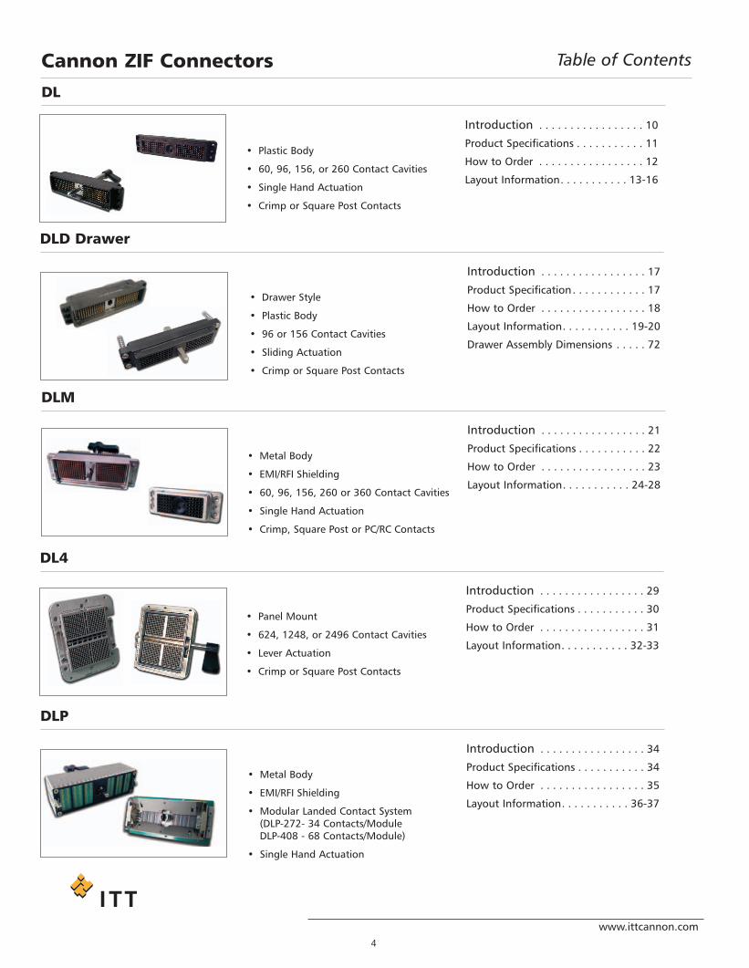
Introduction . . . . . . . . . . . . . . . . . 10
Product Specifications . . . . . . . . . . . 11
How to Order . . . . . . . . . . . . . . . . . 12
Layout Information. . . . . . . . . . . 13-16
• Plastic Body
• 60, 96, 156, or 260 Contact Cavities
• Single Hand Actuation
• Crimp or Square Post Contacts
DL
Introduction . . . . . . . . . . . . . . . . . 21
Product Specifications . . . . . . . . . . . 22
How to Order . . . . . . . . . . . . . . . . . 23
Layout Information. . . . . . . . . . . 24-28
• Metal Body
• EMI/RFI Shielding
• 60, 96, 156, 260 or 360 Contact Cavities
• Single Hand Actuation
• Crimp, Square Post or PC/RC Contacts
DLM
Introduction . . . . . . . . . . . . . . . . . 17
Product Specification. . . . . . . . . . . . 17
How to Order . . . . . . . . . . . . . . . . . 18
Layout Information. . . . . . . . . . . 19-20
Drawer Assembly Dimensions . . . . . 72
• Drawer Style
• Plastic Body
• 96 or 156 Contact Cavities
• Sliding Actuation
• Crimp or Square Post Contacts
DLD Drawer
Introduction . . . . . . . . . . . . . . . . . 29
Product Specifications . . . . . . . . . . . 30
How to Order . . . . . . . . . . . . . . . . . 31
Layout Information. . . . . . . . . . . 32-33
• Panel Mount
• 624, 1248, or 2496 Contact Cavities
• Lever Actuation
• Crimp or Square Post Contacts
DL4
Introduction . . . . . . . . . . . . . . . . . 34
Product Specifications . . . . . . . . . . . 34
How to Order . . . . . . . . . . . . . . . . . 35
Layout Information. . . . . . . . . . . 36-37
• Metal Body
• EMI/RFI Shielding
• Modular Landed Contact System(DLP-272- 34 Contacts/ModuleDLP-408 - 68 Contacts/Module)
• Single Hand Actuation
DLP
www.ittcannon.com
Cannon ZIF Connectors Table of Contents
Project1.qxd:Layout 1 11/12/09 2:33 PM Page 4

5
www.ittcannon.com
Introduction . . . . . . . . . . . . . . . . . 40
Selection Guide . . . . . . . . . . . . . . . . 40
Junction Shells, Plastic . . . . . . . . 41-42
Backshells, Metal . . . . . . . . . . . . . . . 43
Actuating Handles . . . . . . . . . . . . . . 44
Protective Covering. . . . . . . . . . . 44-45
Polarizing Posts . . . . . . . . . . . . . . . . 46
Shells (EMI/RFI) . . . . . . . . . . . . . . . . 47
• Cannon offers a large selection ofaccessories to meet a variety ofapplication requirements
• Allows customization using standardcomponents
Accessories
Introduction . . . . . . . . . . . . . . . . . 48
Buss Contacts . . . . . . . . . . . . . . . . . 49
Crimp Contacts-Loose / Reeled . . . . 50• Crimp and Buss contacts are available
loose or reeled
• Accommodates wire sizes #42-#18AWG
• Customer installed. Fieldinstallable/removable
Introduction . . . . . . . . . . . . . . . . . 51
Hand Crimp Tools . . . . . . . . . . . . . . 51
Extraction Tools . . . . . . . . . . . . . . . . 52
Assembly Instructions. . . . . . . . . 53-55
Lease Automatic Tooling. . . . . . . 56-57
• Cannon offers hand crimp tooling forlow volume applications
• Contact extraction tools
• Automatic tooling can be leased forlarge volume applications
Tools and Assembly
Introduction . . . . . . . . . . . . . . . . . 38
Product Specifications . . . . . . . . . 38Layout Information. . . . . . . . . . . . 39
• Metal Body
• EMI / RFI Shielding
• 260 Contacts
• Small form factor. For portable equipment
QLC
Cannon ZIF Connectors Table of Contents
Contacts
PCB Hole Pattern and Pad Layout . . . . . . . . . . . . . . . . . . . . . . . . . . . . . . . . . . . . . . . . . . . 58-65Panel Cutouts . . . . . . . . . . . . . . . . . . . . . . . . . . . . . . . . . . . . . . . . . . . . . . . . . . . . . . . . . . 66-68Contact Cavity Arrangements. . . . . . . . . . . . . . . . . . . . . . . . . . . . . . . . . . . . . . . . . . . . . . 69-71
Project1.qxd:Layout 1 11/12/09 2:33 PM Page 5

6
Cannon ZIF Connectors Product Overview Guide
www.ittcannon.com
DDLL DDLLDD DDLLMM DDLL44 DDLLPP 113366 -- 227722 DDLLPP 440088 QQLLCC
TTyyppee Plug & Receptacle Plug & Receptacle Plug & Receptacle Plug & Receptacle Plug & Receptacle Plug & Receptacle Plug & ReceptacleBBooddyy Plastic Plastic Metal Metal Metal Metal Metal
BBooddyy MMaatteerriiaall Thermoplastic Thermoplastic Aluminum Aluminum Aluminum Zinc Alloy ZincAAvvaaiillaabbllee LLaayyoouuttss
60; 96; 156; and260 signal
96 and 156 signal 60; 96; 156 260and 360 signal
624 and 1248signal
136, 204 and 272signal
408 signal 260 signal
CCrriimmpp CCoonnttaaccttss yes yes yes yes - - -SSqquuaarree PPoossttCCoonnttaaccttss yes yes yes yes - - -
PPCC//RRCC CCoonnttaaccttss - - yes - - - -PPrreessssffiitt CCoonnttaaccttss yes (1) - yes (2) - no yes no
CCuurrrreennttRRaattiinngg
5 A max. (3) 5 A max. (3) 5 A max. (3) / 4 Amax. (4)
5 A max. (3) 0,5 A max. 0,3 A max 0,5A max
CCoonnttaacctt RReessiissttaannccee
15 milliohms max. 15 milliohmsmax.
15 milliohmsmax.
15 milliohmsmax.
30 milliohmsmax. (Initial)
30 milliohmsmax. (Initial)
100 milliohmsmax (includesbulk resistance)
20 milliohms max.(5)
20 milliohmsmax. (5)
20 milliohmsmax. (5)
20 milliohmsmax. (5)
30 milliohmmsmax. (4)
CCoonnttaacctt MMaatteerriiaall20 or 50 inches
gold plated copper alloy
50 inches goldplated
copper alloy
20 or 50 inchesgold plated copper alloy
20 or 50 inchesgold plated copper alloy
Gold plated copper Alloy
Gold plated copper Alloy
40 inch goldplated copper
alloyOOppeerraattiinngg
tteemmppeerraattuurree -55°C to 105°C-55°C to 105°C
-55°C to 105°C -55°C to 71°C -55°C to 85°C -55°C to 85°C -55°C to 85°C
RRooHHSS ccoommpplliiaanntt yes yes yes yes yes yes yes
FFaaccttoorryy tteerrmmiinnaatteedd
Solder to PCBThrough Hole
Solder to PCBThrough Hole
Solder to PCBThrough Hole
Solder to PCBThrough Hole
Solder to PCBThrough Hole Press-fit
Solder to PCBthrough hole
MMaattiinngg ccyycclleess 10.000 min. 100,000 min. 10.000 min. 20,000 min. 10,000 max 10,000 max 20,000 max
EEMMII//RRFFII sshhiieellddiinngg - - yes yes yes yes yesAAcccceessssoorriieess See Pages 40-47Actuating handles yes - yes included yes yes yesProtective Cover(Rubber) (6) yes
-yes yes
- - -
Protective Cover(Plastic) (7) yes
-yes -
yes - -
Metals Shell forEMI/RFI shielding yes (5)
-- -
- - -
Plastic Junction Shell yes-
yes -- - -
Cable Clamps yes - yes - - - -
Metals Backshell yes - yes - - - -
Polarizing Posts yes - yes - - - -PPaaggee nnuummbbeerr 1100--1166 1177--2200 2211--2288 2299--3333 3344--3366 3377 3388--3399
Notes:(1) DL5 only(2) DLM5 only(3) Crimp or Square Post Contacts(4) PC/RC contact(5) Specification for Crimp Contacts smaller than 28 AWG
Project1.qxd:Layout 1 11/12/09 2:33 PM Page 6

7www.ittcannon.com
Dimensions shown in mm (inch)Specifications and dimensions subject to change
Product FeaturesCannon ZIF Connectors
Our DLP connector uses our landed contact system. Modules of 34 or 68 contacts each are populated in tothe receptacle to the customer’s requirements. These contacts are positioned to land on pads that aredesigned into the customer supplied PCB and mounted to the plug connector housing. When mated, thecontacts do not touch the pads on the plug PCB. Once the handle is rotated and locked, the shape of thereceptacle contact generates a slight wipe on the plug PCB pads.
The mechanical function of the new DLP ZIF connectorA quarter turn of knob (shaft) mates all the contact at once by the function of cam and bearing.
Contact
Plug side PCB
Bearing
Cam shaft
Project1.qxd:Layout 1 11/12/09 2:33 PM Page 7

8www.ittcannon.com
Dimensions shown in mm (inch)Specifications and dimensions subject to change
Cannon ZIF Connectors Product Features
The long life and rapid mating are achieved through the use of our Zero Insertion Force design.Contact in the plug and receptacle do not touch each other while the connector halves are beingengaged.
Step 1:The plug is placed over the receptacle.
Step 2:A “quarter turn” of an actuatingshaft mates all contacts at once.
Step 3:The same “quarter turn” alsophysically locks the connectorhalves together.
Connector engagement force is zero, and the only wear on the contacts occurs as they arepressed together and lightly wiped past each other during the camming and locking operation.
Project1.qxd:Layout 1 11/12/09 2:33 PM Page 8
9www.ittcannon.com
Dimensions shown in mm (inch)Specifications and dimensions subject to change
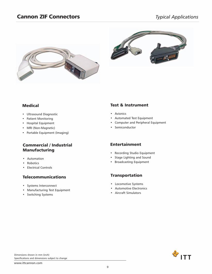
Cannon ZIF Connectors Typical Applications
Medical
• Ultrasound Diagnostic• Patient Monitoring• Hospital Equipment
• MRI (Non-Magnetic)
• Portable Equipment (Imaging)
Test & Instrument
• Avionics• Automated Test Equipment• Computer and Peripheral Equipment
• Semiconductor
Commercial / Industrial Manufacturing
• Automation• Robotics• Electrical Controls
Entertainment
• Recording Studio Equipment• Stage Lighting and Sound• Broadcasting Equipment
Telecommunications
• Systems Interconnect• Manufacturing Test Equipment• Switching Systems
Transportation
• Locomotive Systems• Automotive Electronics• Aircraft Simulators
Project1.qxd:Layout 1 11/12/09 2:33 PM Page 9

10www.ittcannon.com
Dimensions shown in mm (inch)Specifications and dimensions subject to change
Cannon ZIF Connectors DL - Plastic Body
The Cannon DL Series of Zero Insertion Force (ZIF) connectors fill the need in the medical, commercial / indus-trial, computer, and peripheral equipment market places forlow-cost, high performance, multiple-wire power and signalconnectors.DL connectors feature: a minimum rated life of 10,000 complete mating and unmating cycles with no performanceloss; can be mated and unmated in less than two secondseven with as many as 2496 contacts; and they cost less(often as much as 25% less) per mated line than singular
Simple. Effective. Reliable. Durable
Combining their special deign with commercial-grade materials and low cost crimp, PCB, and wrappable hermaph-roditic contacts, that may be hand or machine terminated,makes the DL Series of ZIF connectors the finest low-cost-per-mated-line I/0 connectors available today.
The ambient temperature curves shown represent the rated current carrying capacity of the CannonDL1/2/3/4, electrical connectors, derated to 80%of the values recorded during the methods specified byInternational Electro-Technical Commission Document 48 (1975).Current was applied to the total connector (all contacts) in one-half ampere increments and maintained ateach current level until thermal stability was achieved. A thermocouple inserted into the “hottest area” ofeach connector then measured the connector temperature at the same time that an ambient temperaturereading was taken. The difference between the two measured values is the heat rise or self-heating createdsolely by the current flow, and this temperature rise for the current level was deducted from the insulatormaterial rated temperature. These values were then derated to 80% to obtain the curves shown.
DL1 DL2 DL3
high-density rack-and-panel connectors.
Derating Curves
Project1.qxd:Layout 1 11/12/09 2:33 PM Page 10

Performance DataCurrent Rating: 5 A max - Crimp/Square Post/PCB contact
10 A, 20 A, 30 A, 40 A, 50 A, 60 A max - Buss contact
Dielectric Withstanding Voltage: 1200 VAC RMS - Crimp/Square Post Contact
Operating Temperature: -55°C to 105°C (DL/DLM/DLD)
Insulation Resistance: 5000 Megaohms minimum
Durability: 10,000 Cycles minimum
Contact Resistance: 15 mΩ max. - Crimp/Square Post Contact20 mΩ max. - Crimp #32 AWG - #30 AWG Contact
Insulation Resistance: 5000 MΩ min.
Wire Accommodation: #42 AWG - #18 AWG
Contact Retention: 8 lb (35.585 N) minimum
11
www.ittcannon.com
Cannon ZIF Connectors DL - Plastic Body
Standard Materials and FinishesDL Housing: Glass Filled Thermoplastic, UL 94V-1 rated, Color: Black
Crimp Contacts and - Copper alloy, 20 or 50 microinches gold over 50 microinches nickel in mated area, Square Post Contacts: gold flash on balance
Actuating Camshaft: Stainless steel, Passivated
Insulator Retainer (Plug Only) Stainless steel, Passivated
Electrical DataNo. of Contacts: 60, 96, 156, and 260 signal
Wire Size: #18 AWG through #42 AWG
Contact Termination: - Crimp- Square Post- Wrap Post- Buss- Pressfit
Mechanical DataActuation: Single Hand
Coupling: Rotating latch
Polarization: Polarizing Posts
Contact Spacing: 2,54 (0.100) Square Grid
Shell Styles: Plug and Receptacle
Dimensions shown in mm (inch)Specifications and dimensions subject to change
Project1.qxd:Layout 1 11/12/09 2:33 PM Page 11

12www.ittcannon.com
Dimensions shown in mm (inch)Specifications and dimensions subject to change
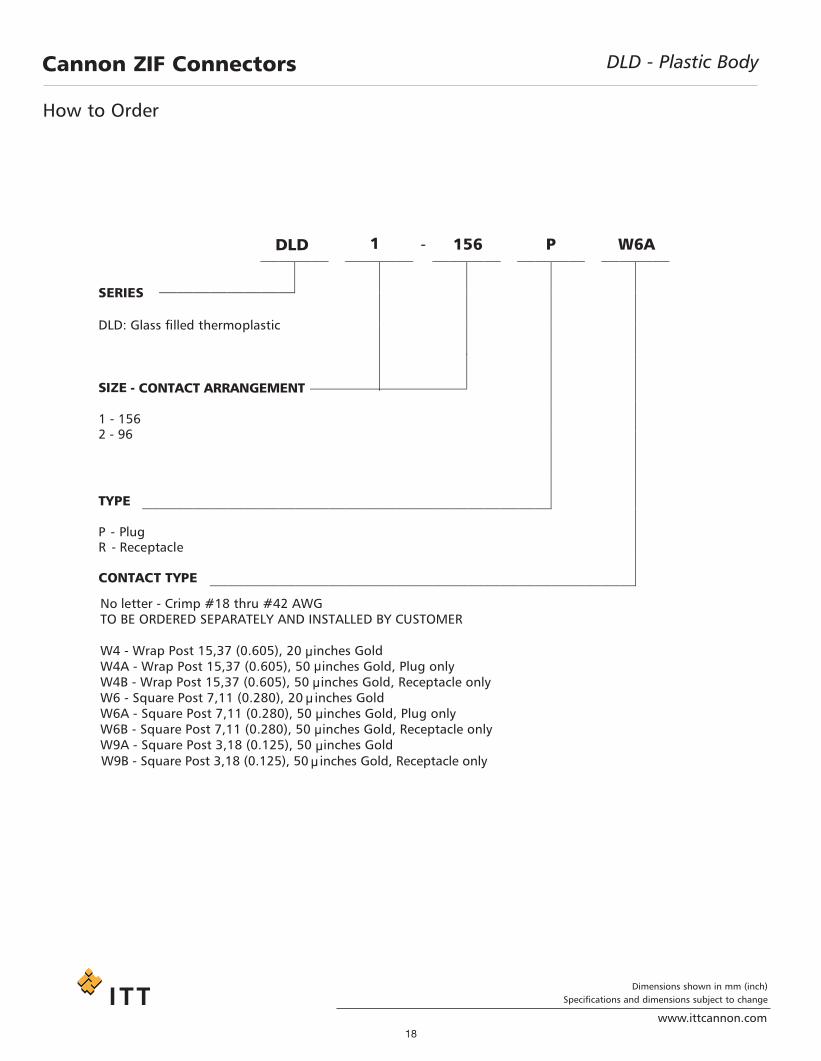
DL - Plastic BodyCannon ZIF Connectors
DL 1 - 156 P
W6
SERIES
DL : Thermo filled thermoplastic
1 - 156
2 - 96 3 - 60 5 - 260
TYPE
P - PlugR - Receptacle
CONTACT TYPE
SIZE - CONTACT ARRANGEMENT
No letter - Crimp #18 thru #42 AWG TO BE ORDERED SEPARATELY AND INSTALLED BY CUSTOMER
W4 - Wrap Post 15,37 (0.605), 20 inches GoldW4A - Wrap Post 15,37 (0.605), 50 inches Gold, Plug onlyW4B - Wrap Post 15,37 (0.605), 50 inches Gold, Receptacle onlyW6 - Square Post 7,11 (0.280), 20 inches GoldW6A - Square Post 7,11 (0.280), 50 inches Gold, Plug onlyW6B - Square Post 7,11 (0.280), 50 inches Gold, Receptacle only
F - Pressfit, 20 inches Gold, DL5 Receptacle only
W9A - Square Post 3,18 (0.125), 50 inches Gold, Plug onlyW9B - Square Post 3,18 (0.125), 50 inches Gold, Receptacle only
How to Order
Project1.qxd:Layout 1 11/12/09 2:33 PM Page 12

13
www.ittcannon.com
Dimensions shown in mm (inch)Specifications and dimensions subject to change
DL - Plastic Body - Crimp ContactsCannon ZIF Connectors
Description A B C D E F G HDL3-60P 65,80 57,91 50,55 11,89 24,90 39,19 24,90 49,02
(2.592) (2.280) (1.992) (0.466) (0.981) (1.543) (0.981) (1.931)DL2-96P 65,80 57,91 50,60 19,38 28,12 39,19 24,05 50,60
(2.592) (2.280) (1.994) (.763) (1.108) (1.543) (0.947) (1.994)DL1-156P 108,00 100,03 92,26 16,26 24,90 54,81 20,10 92,10
(4.255) (3.938) (3.631) (0.640) (0.980) (2.158) (0.792) (3.626)DL5-260P 108,00 100,03 92,26 26,00 35,00 54.26 30,30 92,10
(4.255) (3.938) (3.631) (1.024) (1.378) (2.136) (1.193) (3.626)
Description A B C D E G HDL3-60R 65,80 57,91 50,50 11,89 24,90 19,18 49,02
(2.592) (2.280) (1.988) (0.468) (0.981) (0.755) (1.931)DL2-96R 65,80 57,91 50,60 19,38 28,12 24,05 50,60
(2.592) (2.280) (1.994) (.763) (1.108) (0.947) (1.994)DL1-156R 108,00 100,03 92,10 16,26 24,90 20,10 92,10
(4.255) (3.938) (3.622) (0.640) (0.980) (0.792) (3.626)DL5-260R 108,00 100,03 92,10 26,00 35,00 30,30 92,10
(4.255) (3.938) (3.622) (1.024) (1.378) (1.193) (3.626)Notes:Crimp contacts are to be ordered separately and to be installed by customer, see pages 49-50.
A
4X Ø 3,03 (.119)
7,92 (.312)
6,35(.250)
23,10(.910)
C AMSHAF TTURNING DIRE C TIO N
B
C D
E F
G
H
4X Ø 3,03 (.119)
7,75 (.305)
6,35 (.250)
20,32 (.800)
A
B
CD
E
G
H
• Order Actuating Handle Kit sold separately, see page 44.• Crimp Contacts are to be ordered separately and to be
installed by customer, see pages 48-50.
• For contact cavity arrangements see pages 69-70.• For panel cutout and mounting hole pattern, see page 66.• For PC hole pattern, see pages 59-61.
• Crimp Contacts are to be ordered separately and to be installed by customer, see pages 48-50.
• For contact cavity arrangements see pages 69-70.
• For panel cutout and mounting hole pattern, see page 66.
• For PC hole pattern, see pages 59-61.
Plug
Receptacle
Project1.qxd:Layout 1 11/12/09 2:33 PM Page 13

Dimensions shown in mm (inch)Specifications and dimensions subject to change
www.ittcannon.com14
Cannon ZIF Connectors DL - Plastic Body - Square / Wrap Post Contacts
Description A B C D E F G H I J LDL3-60PW4DL3-60PW4A
65,80 57,91 50,55 11,89 24,90 34,54 19,94 49,02 5 4 15,37(2.592) (2.280) (1.992) (.468) (.981) (1.360) (.785) (1.931) spaces spaces (.605)
DL3-60PW6DL3-60PW6A
65,80 57,91 50,55 11,89 24,90 34,54 19,94 49,02 5 4 7,11(2.592) (2.280) (1.992) (.468) (.981) (1.360) (.785) (1.931) spaces spaces (.280)
DL3-60PW9A 65,80 57,91 50,55 11,89 24,90 34,54 19,94 49,02 5 4 3,18(2.592) (2.280) (1.992) (.468) (.981) (1.360) (.785) (1.931) spaces spaces (.125)
DL2-96PW4DL2-96PW4A
65,80 57,91 50,60 19,38 28,12 34,54 24,05 50,60 7 6 15,37(2.592) (2.280) (1.994) (.763) (1.108) (1.360) (.947) (1.994) spaces spaces (.605)
DL2-96PW6DL2-96PW6A
65,80 57,91 50,60 19,38 28,12 34,54 24,05 50,60 7 6 7,11(2.592) (2.280) (1.994) (.763) (1.108) (1.360) (.947) (1.994) spaces spaces (.280)
DL2-96PW9A 65,80 57,91 50,60 19,38 28,12 34,54 24,05 50,60 7 6 3,18(2.592) (2.280) (1.994) (.763) (1.108) (1.360) (.0947) (1.994) spaces spaces (.125)
DL1-156PW4DL1-156PW4A
108,00 100,03 92,26 16,26 24,90 50,16 20,10 92,10 5 12 15,37(4.255) (3.983) (3.631) (.640) (.981) (1.975) (0.792) (3.626) spaces spaces (.605)
DL1-156PW6DL1-156PW6A
108,00 100,03 92,26 16,26 24,90 50,16 20,10 92,10 5 12 7,11(4.255) (3.983) (3.631) (.640) (.981) (1.975) (.792) (3.626) spaces spaces (.380)
DL1-156PW9A 108,00 100,03 92,26 16,26 24,90 50,16 20,10 92,10 5 12 3,18(4.255) (3.983) (3.631) (.640) (.981) (1.975) (.792) (3.626) spaces spaces (.125)
DL5-260PW4DL5-260PW4A
108,00 100,03 92,26 26,00 35,00 49,61 30,30 92,10 9 12 15,37(4.255) (3.983) (3.631) (1.024) (1.378) (1.953) (1.193) (3.626) spaces spaces (.604)
DL5-260PW6DL5-260PW6A 108,00 100,03 92,26 26,00 35,00 49,61 30,30 92,10 9 12 7,11
(4.255) (3.983) (3.631) (1.024) (1.378) (1.953) (1.193) (3.626) spaces spaces (.280)
DL5-260PW9A 108,00 100,03 92,26 26,00 35,00 49,61 30,30 92,10 9 12 3,18(4.255) (3.983) (3.631) (1.024) (1.378) (1.953) (1.193) (3.626) spaces spaces (.125)
Notes:Front removable 0,64 (0.025) square posts 2,54 (0.100) Centers.1 space at 2,54 (0.100)
D
B
4X Ø 3,03 (.119)
A
C
E
7,92 (.312)
F0,64 (.025)
L
6,35 (.250)
27,75(1.093)
I @ 2,54 (.100) = 12,70 (.500)
J @ 2,54 (.100) = 30,48 (1.200)
C AMSHAF TTURNING DIRE C TIO N G
H
J @ 2,54 (.100) = 30,48 (1.200)
• Order Actuating Handle Kit sold separately, see page 44.
• For contact cavity arrangements see pages 69-70.
• For panel cutout and mounting hole pattern, see page 66.
• For PC hole pattern, see pages 59-61.
Plug
Project1.qxd:Layout 1 11/12/09 2:33 PM Page 14

Dimensions shown in mm (inch)Specifications and dimensions subject to change
www.ittcannon.com15
Cannon ZIF Connectors DL - Plastic Body - Square / Wrap Post Contacts
Description A B C D E G H I J LDL3-60RW4DL3-60RW4B
65,80 57,91 50,50 11,89 24,90 19,94 49,02 5 4 15,37(2.592) (2.280) (1.988) (.466) (.980) (0.785) (1.931) spaces spaces (.605)
DL3-60RW6DL3-60RW6B
65,80 57,91 50,50 11,89 24,90 19,94 49,02 5 4 7,11(2.592) (2.280) (1.988) (.466) (1.360) (.785) (1.931) spaces spaces (.280)
DL3-60RW9B 65,80 57,91 50,50 11,89 24,90 19,94 49,02 5 4 3,18(2.592) (2.280) (1.988) (0.466) (1.360) (.785) (1.931) spaces spaces (.125)
DL2-96TW4DL2-96RW4B
65,80 57,91 50,60 19,38 28,12 24,05 50,60 7 6 15,37(2.592) (2.280) (1.994) (.763) (1.108) (,947) (1.994) spaces spaces (.605)
DL2-96RW6DL2-96RW6B
65,80 57,91 50,60 19,38 28,12 24,05 50,60 7 6 7,11(2.592) (2.280) (1.994) (.763) (1.108) (,947) (1.994) spaces spaces (.280)
DL2-96RW9B 65,80 57,91 50,60 19,38 28,12 24,05 50,60 7 6 3,18(2.592) (2.280) (1.994) (.763) (1.108) (,947) (1.994) spaces spaces (.125)
DL1-156RW4DL1-156RW4B
108,00 100,03 92,00 16,26 24,90 20,10 92,10 5 12 15,37(4.255) (3.983) (3.622) (.640) (.980) (.792) (3.626) spaces spaces (.605)
DL1-156RW6DL1-156RW6B
108,00 100,03 92,00 16,26 24,90 20,10 92,10 5 12 7,11(4.255) (3.983) (3.622) (.640) (.980) (.792) (3.626) spaces spaces (.380)
DL1-156RW9B 108,00 100,03 92,00 16,26 24,90 20,10 92,10 5 12 3,18(4.255) (3.983) (3.622) (.640) (.980) (.792) (3.626) spaces spaces (.125)
DL5-260RW4DL5-260RW4B
108,00 100,03 92,00 26,00 35,00 30,30 92,10 9 12 15,37(4.255) (3.983) (3.622) (1.024) (1.378) (1.193) (3.626) spaces spaces (.604)
DL5-260RW6DL5-260RW6B
108,00 100,03 92,00 26,00 35,00 30,30 92,10 9 12 7,11(4.255) (3.983) (3.622) (1.024) (1.378) (1.193) (3.626) spaces spaces (.280)
DL5-260RW9B 108,00 100,03 92,00 26,00 35,00 30,30 92,10 9 12 3,18(4.255) (3.983) (3.622) (1.024) (1.378) (1.193) (3.626) spaces spaces (.125)
Notes:
Front removable 0,64 (0.025) square posts 2,54 (0.100) Centers.
1 space at 2,54 (0.100)
D
B
4X Ø 3,03 (.119)
A
C
E
7,75 (.305)
0,64 (.025)
L
6,35 (.250)
24,97 (.983)
I @ 2,54 (.100)= 12,70 (.500)
J @ 2,54 (.100)= 30,48 (1.200)
J @ 2,54 (.100)= 30,48 (1.200)
G
H
• For contact cavity arrangements see pages 69-70.
• For panel cutout and mounting hole pattern, see page 66.
• For PC hole pattern, see pages 59-61.
Receptacle
Project1.qxd:Layout 1 11/12/09 2:33 PM Page 15

Dimensions shown in mm (inch)Specifications and dimensions subject to change
www.ittcannon.com16
Cannon ZIF Connectors DL5 - Plastic Body - Pressfit Contacts
Receptacle only
• For contact cavity arrangements see page 70.
• For panel cutout and mounting hole pattern, see page 66.
• For PC hole pattern, see page 62.
Part Number Nomenclature11987-0008 DL5-260R-F
4.283
3.620
3.937
3.343
Project1.qxd:Layout 1 11/12/09 2:33 PM Page 16

Dimensions shown in mm (inch)Specifications and dimensions subject to change
www.ittcannon.com17
DLD - Plastic BodyCannon ZIF Connectors Cannon has combined Zero Insertion Force (ZIF) technologywith remote electrical engagement. The DLD Drawer allows themovement of a drawer or panel to effortlessly mate/unmate theconnector halves. As an example: electrical sub-systems can beeasily removed for service, interchangability, or portability.By specifying DLD Drawer interconnect systems, your packagingdesign is simplified as the need for expensive, complicated, andspace-consuming manual actuation mechanisms is eliminated.TIght space requirements no longer restrict your use of ZIF con-nectors.The contacts in the DLD Drawer product line do not touch eachother while the connector halves are mating. This unique ZIFtechnology, introduced in the Cannon DL series in the early1970’s, has time-tested proven reliability and durability.The DLD Drawer’s remote mating feature utilizes the axial thrustof a cam to move and mate the contacts. At the end of the camtravel, the cam ramps on a flat surface thereby negating anyuncoupling forces.This rack-and-panel connector is available with crimp or square post contacts, allowing cable, PCB, or flat-flex termination.
Standard Materials and FinishesDLD Housing: Glass Filled Thermoplastic, UL 94V-1 rated, Color: Black
Crimp Contacts: Copper alloy, 20 or 50 microinches gold over 50 microinches nickel in mated area, gold flash on balance
Insulator Retainer (1): Stainless steel, Passivated
Actuating Camshaft (2): Stainless steel
Spring Mounting Screw (2): Stainless steel, Passivated
Electrical DataNo. of Contacts: 96 and 156 signal
Wire Size: #18 AWG through #42 AWGContact Termination: Crimp, Square Post, Wrap Post, Buss
Mechanical DataActuation: Sliding
Coupling: Guide Cam
Polarization: Polarizing Posts
Contact Spacing: 2,54 (.100) Square Grid
Shell Styles: Plug and Receptacle
Performance DataDielectric Withstanding
Voltage: 1200 VAC RMS - Crimp/Square Post Contact
Insulation Resistance 5000 Megaohms minimum
Durability: 100,000 Cycles minimum
Contact Resistance: - 15 milliohms maximum - Crimp/Square Post Contact- 20 milliohms maximum - Crimp #30- #32 AWG contact
Contact Retention: 6 lb (35,564 N) minimum
Project1.qxd:Layout 1 11/12/09 2:33 PM Page 17
18www.ittcannon.com
Dimensions shown in mm (inch)Specifications and dimensions subject to change
DLD - Plastic BodyCannon ZIF Connectors
- 156 P
W6A
SERIES
DLD: Glass filled thermoplastic
SIZE
1 - 156
2 - 96
TYPE
P - Plug R - Receptacle
CONTACT TYPE
DLD 1
- CONTACT ARRANGEMENT
No letter - Crimp #18 thru #42 AWG TO BE ORDERED SEPARATELY AND INSTALLED BY CUSTOMER
W4 - Wrap Post 15,37 (0.605), 20 inches GoldW4A - Wrap Post 15,37 (0.605), 50 inches Gold, Plug onlyW4B - Wrap Post 15,37 (0.605), 50 inches Gold, Receptacle onlyW6 - Square Post 7,11 (0.280), 20 inches GoldW6A - Square Post 7,11 (0.280), 50 inches Gold, Plug onlyW6B - Square Post 7,11 (0.280), 50 inches Gold, Receptacle onlyW9A - Square Post 3,18 (0.125), 50 inches GoldW9B - Square Post 3,18 (0.125), 50 inches Gold, Receptacle only
How to Order
Project1.qxd:Layout 1 11/12/09 2:33 PM Page 18

19www.ittcannon.com
Dimensions shown in mm (inch)Specifications and dimensions subject to change
DLD - Plastic Body Crimp Contacts Cannon ZIF Connectors
Description A B C D E F G HDLD2-96R 65,80 57,91 50,60 19,38 28,12 46,87 24,05 50,60
(2.592) (2.280) (1.994) (.763) (1.108) (1.845) (0.947) (1.994)DLD-156R 108,00 100,03 92,00 16,26 24,90 46,86 20,10 92,10
(4.255) (3.983) (3.622) (0.640) (0.980) (1.845) (0.792) (3.626)
Description A B C D E G HDLD2-96P 65,80 57,91 50,60 19,38 26,12 24,05 50,60
(2.592) (2.280) (1.994) (0.763) (1.108) (0.947) (1.994)DLD1-156P 108,00 100,03 92,26 16,26 24,90 20,10 92,10
(4.255) (3.983) (3.631) (0.640) (0.980) (0.792) (3.626)
A
C
E
B D
4X Ø 3,03(.119)
7,92 (.312)
23,10(.910)
6,35 (.250)
G
H
CB
D
E
127,81 (5.032) RE FA
7,75 (.305)
6,35 (.250)
F
2,03 (.080) RE F3,18 (.125) RE F
C AM, AC TUATO RRE C E PTAC LE C O NNE C TO R
ASSE MBLY
4X SC RE W, SPRINGMO UNTING
F RO NT MO UNTINGPLATE -ASSE MBLY
[SUPPLIE D BY C USTO ME R]RE AR PANE L, MO UNTING
[STATIO NARY][SUPPLIE D BY C USTO ME R]
4X SPRING ,C O MPRE SSIO N
NO. 4-40 UNC SC RE W[SUPPLIE D BY C USTO ME R]
20,32 (.800)
G
H
Plug
Receptacle
• Crimp contacts are to be ordered separately and to be installed by customer, see pages 48-50.
• For contact cavity arrangements see page 69.• For panel cutout and mounting hole pattern, see pages 67-68.
• Crimp contacts are to be ordered separately and to be installed by customer, see pages 48-50.
• For contact cavity arrangements see page 69.• For panel cutout and mounting hole pattern, see pages 67-68.
Project1.qxd:Layout 1 11/12/09 2:33 PM Page 19

Dimensions shown in mm (inch)Specifications and dimensions subject to change
www.ittcannon.com20
DLD - Plastic Body - Square / Wrap Post ContactsCannon ZIF Connectors
Description A B C D E G H I J LDLD2-96PW4DLD2-96PW4A
65,80 57,91 50,60 19,38 28,12 24,05 50,60 7 6 15,37(2.592) (2.280) (1.994) (.763) (1.108) (,947) (1.994) spaces spaces (.605)
DLD2-96PW6DLD2-96PW6A
65,80 57,91 50,60 19,38 28,12 24,05 50,60 7 6 7,11(2.592) (2.280) (1.994) (.763) (1.108) (,947) (1.994) spaces spaces (.280)
DLD2-96PW9A 65,80 57,91 50,60 19,38 28,12 24,05 50,60 7 6 3,18(2.592) (2.280) (1.994) (.763) (1.108) (,947) (1.994) spaces spaces (.125)
DLD1-156PW4DLD1-156PW4A
108,00 100,03 92,26 16,26 24,80 20,10 92,10 5 12 15,37(4.255) (3.983) (3.631) (.640) (.977) (.792) (3.626) spaces spaces (.605)
DLD1-156PW6DLD1-156PW6A
108,00 100,03 92,26 16,26 24,90 20,10 92,10 5 12 7,11(4.255) (3.983) (3.631) (.640) (.980) (.792) (3.626) spaces spaces (.280)
DLD1-156PW9A 108,00 100,03 92,26 16,26 24,90 20,10 92,10 5 12 3,18(4.255) (3.983) (3.631) (.640) (.980) (.792) (3.626) spaces spaces (.125)
Description A B C D E F G H I J LDLD2-96RW4DLD2-96RW4B
65,80 57,91 50,60 19,38 28,12 57,03 24,05 50,60 7 6 15,37(2.592) (2.280) (1.994) (.763) (1.108) (1.245) (,947) (1.994) spaces spaces (0.605)
DLD2-96RW6DLD2-96RW6B
65,80 57,91 50,60 19,38 26,12 57,03 24,05 50,60 7 6 7,11(2.592) (2.280) (1.994) (.763) (1.108) (1.245) (,947) (1.994) spaces spaces (0.280)
DLD1-156RW4DLD1-156RW4B
108,00 100,03 92,26 16,26 24,80 57,03 20,10 92,10 5 12 15,37(4.255) (3.983) (3.631) (.640) (.977) (1.245) (.792) (3.626) spaces spaces (0.605)
DLD1-156RW6DLD1-156RW6B
108,00 100,03 92,00 16,26 24,90 57,03 20,10 92,10 5 12 7,11(4.255) (3.983) (3.622) (.640) (.980) (1.245) (.792) (3.626) spaces spaces (0.380)
DLD1-156RW9A 108,00 100,03 92,00 16,26 24,90 57,03 20,10 92,10 5 12 7,11(4.255) (3.983) (3.622) (.640) (.980) (1.245) (.792) (3.626) spaces spaces (0.380)
E
DB
4X Ø 3,03(.119)
7,92 (.312)
27,75(1.093)
0,64 (.025)
L
6,35 (.250)
32
1A
45
6
BCDEFGHJKLMNS PRU TVWXYZ
A
bc
BCDEFGHJKLMNS PRU TVWXYZbc a
H
I @ 2,54 (.100)= 12,70 (.500)
12 SPAC E S @ 2,54 (.100)= 30,48 (1.200)
G
J @ 2,54 (.100)= 30,48 (1.200)
A
C
C D
127,81 (5.032) RE F
BA
E
7,75 (.305)
0,64 (.025)
F
2,03 (.080) RE F
3,18 (.125) RE F
4X SC RE W, SPRINGMO UNTING
NO. 4-40 UNC SC RE W
[SUPPLIE D BY C USTO ME R]
L
C AM, AC TUATO RRE C E PTAC LE C O NNE C TO R
ASSE MBLY
6,35 (.250)
24,97 (.983)
F RO NT MO UNTINGPLATE -ASSE MBLY
[SUPPLIE D BY C USTO ME R]
RE AR PANE L, MO UNTING[STATIO NARY]
[SUPPLIE D BY C USTO ME R]
4X SPRING ,C O MPRE SSIO N
C O NTAC T,WRAP PO ST
A
3 2
1
BCDEFGHJKLMNS PRU TVWXYZ
A
bc
BCDEFGHJKLMNS PRU TVWXYZbc a
64
5
H
G I @ 2,54 (.100)
= 12,70 (.500)
12 SPAC E S @ 2,54 (.100)= 30,48 (1.200)
J @ 2,54 (.100)= 30,48 (1.200)
Plug • For contact cavity arrangements see page 69.
• For panel cutout and mounting hole pattern, see pages 67-68.
• For PC hole pattern, see pages 60-61.
• For contact cavity arrangements see page 69.
• For panel cutout and mounting hole pattern, see pages 67-68.
• For PC hole pattern, see pages 60-61.
Receptacle
Project1.qxd:Layout 1 11/12/09 2:33 PM Page 20

Dimensions shown in mm (inch)Specifications and dimensions subject to change
www.ittcannon.com21
Cannon ZIF Connectors DLM - Metal Body
Cannon has expanded the DL-ZIF series offeringwith the addition of the DLM (Metal Shell) versions. The DLM uses a rugged nickel platedaluminum housing. THe Shield-LockingMechanism feature (see illustration below)ensures uniform mating pressure around theperimeter of the mated connector to create anEMI/RFI shield which facilities compliance ofequipment to CE EMC directives.
The DLM Series connectors are intermateable to the DL(Plastic) versions for backwards/forwards compatibility. The DLM Series are offered with all of the DL plastic contactsfrom crimp, square post, and round PL/RC tail contacts.
The ambient temperature curves shown represent the rated current carrying capacity of the CannonDL1/2/3/4, DLM1/2/3 and DLD1/2 electrical connectors, derated to 80% of the values recorded during themethods specified by International Electro-Technical Commission Document 48 (1975).Current was applied to the total connector (all contacts) in one-half ampere increments and maintained ateach current level until thermal stability was achieved. A thermocouple inserted into the “hottest area” ofeach connector then measured the connector temperature at the same time that an ambient temperaturereading was taken. The difference between the two measured values is the heat rise or self-heating createdsolely by the current flow, and this temperature rise for the current level was deducted from the insulatormaterial rated temperature. These values were then derated to 80% to obtain the curves shown.
DLM1 DLM2 DLM3
Derating Curves
Project1.qxd:Layout 1 11/12/09 2:33 PM Page 21

Dimensions shown in mm (inch)Specifications and dimensions subject to change
www.ittcannon.com22
Standard Materials and Finishes
DLM Housing: Aluminum alloy, nickel plated
DLM Insulator Copper alloy, 20 or 50 microinches gold over 50 microinches nickel in mated area,Crimp Contacts and gold flash on balanceSquare Post Contacts:
PC/RC Contacts: Copper alloy, 20 microinches gold over nickel in mated area, Sn over Nickel in tail area
Actuating Camshaft: Stainless steel, Passivated
Insulator Retainer (Plug only): Stainless steel, Passivated
Electrical Data
No. of Contacts: 60. 96,156, 260 and 360 signal
Wire Size: #18 AWG through #42 AWG
Contact Termination: - PC/RC- Crimp- Square Post- Wrap Post- Buss- Pressfit
Mechanical Data
Actuation: Single Hand
Coupling: Rotating Latch
Polarization: Polarizing Posts
Contact Spacing: 2,54 (.100) Square Grid
Shell Styles: Plug and Receptacle
Actuation: Single Hand
Performance Data
Dielectric Withstanding Voltage: 1200 VAC RMS - Crimp/Square Post Contact
1000 VAC RMS - PC/RC Contacts
Insulation Resistance 5000 Megaohms minimum
Durability: 10,000 Cycles minimum
Contact Resistance: - 15 milliohms maximum - Crimp/Square Post Contact- 20 milliohms maximum - Crimp #30- #32 AWG contact- 30 milliohms maximum - PC/RC Contact
Contact Retention: 8 lb (35,585 N) minimum
DLM - Metal BodyCannon ZIF Connectors
Project1.qxd:Layout 1 11/12/09 2:33 PM Page 22

Dimensions shown in mm (inch)Specifications and dimensions subject to change
www.ittcannon.com23
Cannon ZIF Connectors DLM - Metal Body
SERIES
DLM: Glass filled thermoplastic in nickel plating aluminum housing
SIZE AND CONTACT ARRANGEMENTS
1 - 1562 - 963 - 605 - 2606 - 260
TYPE
P - PlugR - Receptacle
CONTACT TYPE
No letter - Crimp #18 thru #42 AWG. TO BE ORDERED SEPARATELY AND INSTALLED BY CUSTOMER
W4 - Wrap Post 15,37 (0.605) 20 µinches GoldW4A - Wrap Post 15,37 (0.605) 50 µinches Gold, Plug onlyW4B - Wrap Post 15,37 (0.605) 50 µinches Gold, Receptacle onlyW6 - Square Post 7,11 (0.260) 20 µinches GoldW6A - Square Post 7,11 (0.260) 50 µinches Gold, Plug onlyW6B - Square Post 7,11 (0.260) 50 µinches Gold, Receptacle onlyW9A - Square Post 3,18 (0.125), 50 µiinches Gold, Plug onlyW9B - Square Post 3,18 (0.125), 50 µinches Gold, Receptacle onlyC -F - PC / RC 4,50 (0.177), 20 µinches GoldPF- Pressfit - DLM5 Plug and Receptacle only
DLM 2 96 R C
How to Order
Project1.qxd:Layout 1 11/12/09 2:33 PM Page 23

24www.ittcannon.com
Dimensions shown in mm (inch)Specifications and dimensions subject to change
DLM - Metal Body - Crimp ContactsCannon ZIF Connectors
Description A B C D E F G H K
DLM3-60P 65,80 57,91 50,55 11,89 24,90 38,85 24,90 49.02 74,75(2.592) (2.280) (1.992) (.468) (.981) (1.530) (.981) (1.931) (2.945)
DLM2-96P 65,80 57,91 50,60 19,38 28,12 38,85 24,05 50,60 74,75(2.592) (2.280) (1.994) (.763) (1.108) (1.530) (.947) (1.994) (2.945)
DLM1-156P 108,00 100,03 92,00 16,26 24,80 54,10 20,10 92,10 90,00(4.255) (3.983) (3.622) (.640) (.977) (2.132) (0.792) (3.626) (3.546)
DLM5-260P 108,00 100,03 92,00 26,00 35,00 54,81 26,00 92,00 90,00(4.255) (3.983) (3.622) (1.024) (1.378) (2.158) (1.024) (3.626) (3.546)
DLM6-360P 125,00 115,00 104,30 29,00 42,60 69,00 37,80 107,30 104,70(4.921) (4.528) (4.106) (1.142) (1.677) (2.717) (1.488) (4.224) (4,122)
Description A B C D E G H
DLM3-60R 65,80 57,91 50,55 11,89 24,90 19,94 49,02(2.592) (2.280) (1.992) (.468) (.981) (.785) (1.931)
DLM2-96PR 65,80 57,91 50,60 19,38 28,12 24,05 50,60(2.592) (2.280) (1.994) (.763) (1.108) (.947) (1.994)
DLM1-156R 108,00 100,03 92,00 16,26 24,80 20,10 92,10(4.255) (3.983) (3.622) (.640) (.977) (.792) (3.629)
DLM5-260R 108,00 100,03 92,00 26,00 35,00 30,30 92,10(4.255) (3.983) (3.626) (1.024) (1.378) (1.193) (3.629)
DLM6-360R 125,00 115,00 104,30 29,00 42,60 37,80 107,30(4.921) (4.528) (4.106) (1.142) (1.677) (1.488) (4.224)
• Crimp contacts are to be ordered separately and to be installed by customer, see pages 48-50.
• For contact cavity arrangement see pages 69-70.• For panel cutout and mounting hole pattern, see page 66.
Receptacle
Plug • Order Actuating Handle Kit sold separately, see page 44.• Crimp contacts are to be ordered separately and to be
installed by customer, see pages 48-50.
• For contact cavity arrangements see pages 69-70.• For panel cutout and mounting hole pattern, see page 66.
Project1.qxd:Layout 1 11/12/09 2:33 PM Page 24

Dimensions shown in mm (inch)Specifications and dimensions subject to change
www.ittcannon.com25
DLM - Metal Body - Square / Wrap Post ContactsCannon ZIF Connectors
Description A B C D E F G H I J LDLM3-60PW4DLM3-60PW4A
65,80 57,91 50,55 11,89 24,90 34,20 19,94 49,02 5 4 15,37(2.592) (2.280) (1.992) (.468) (.981) (1.347) (.785) (1.931) spaces spaces (.605)
DLM3-60PW6DLM3-60PW6A
65,80 57,91 50,55 11,89 24,90 34,20 19,94 49,02 5 4 15,37(2.592) (2.280) (1.992) (.468) (.981) (1.347) (.785) (1.931) spaces spaces (.605)
DLM3-60PW9A 65,80 57,91 50,55 11,89 24,90 34,20 19,94 49,02 5 4 7,11(2.592) (2.280) (1.992) (.468) (.981) (1.347) (.785) (1.931) spaces spaces (.280)
DLM2-96PW4DLM2-96PW4A
65,80 57,91 50,60 19,38 26,12 34,20 24,05 50,60 7 6 15,37(2.592) (2.280) (1.994) (.763) (1.108) (1.347) (,947) (1.994) spaces spaces (.605)
DLM2-96PW6DLM2-96PW6A
65,80 57,91 50,60 19,38 26,12 34,20 24,05 50,60 7 6 7,11(2.592) (2.280) (1.994) (.763) (1.108) (1.347) (,947) (1.994) spaces spaces (.280)
DLM2-96PW9A 65,80 57,91 50,60 19,38 26,12 34,20 24,05 50,60 7 6 3,18(2.592) (2.280) (1.994) (.763) (1.108) (1.347) (,947) (1.994) spaces spaces (.125)
DLM1-156PW4DLM1-156PW4A
108,00 100,03 92,00 16,26 24,90 49,45 20,10 92,10 5 12 15,37(4.255) (3.983) (3.622) (.640) (.981) (1.948) (.792) (3.626) spaces spaces (.605)
DLM1-156PW6DLM1-156PW6A
108,00 100,03 92,00 16,26 24,90 49,45 20,10 92,10 5 12 7,11(4.255) (3.983) (3.622) (.640) (.981) (1.948) (.792) (3.626) spaces spaces (.280)
DLM1-156PW9A 108,00 100,03 92,00 16,26 24,90 49,45 20,10 92,10 5 12 3,18(4.255) (3.983) (3.622) (.640) (.981) (1.948) (.792) (3.626) spaces spaces (.125
DLM5-260PW4DLM5-260PW4A 108,00 100,03 92,00 26,00 35,00 49,90 30,30 92,10 9 12 15,37
(4.255) (3.983) (3.622) (1.024) (1.378) (1.965) (1.193) (3.626) spaces spaces (.604)
DLM5-260PW6DLM5-260PW6A
108,00 100,03 92,00 26,00 35,00 49,90 30,30 92,10 9 12 7,11(4.255) (3.983) (3.622) (1.024) (1.378) (1.965) (1.193) (3.626) spaces spaces (.280)
DLM5-260PW9A 108,00 100,03 92,00 26,00 35,00 49,90 30,30 92,10 9 12 3,18(4.255) (3.983) (3.622) (1.024) (1.378) (1.965) (1.193) (3.626) spaces spaces (.125)
DLM6-260PW4DLM6-360PW4A
125,00 115,00 104,30 29,00 42,60 64,30 37,80 107,30 9 14 15,37(4.291) (4.528) (4.106) (1.142) (1.677) (2.531) (1.488) (4.224) spaces spaces (.604)
DLM6-360PW6DLM6-360PW6A
125,00 115,00 104,30 29,00 42,60 64,30 37,80 107,30 9 14 7.11(4.291) (4.528) (4.106) (1.142) (1.677) (2.531) (1.488) (4.224) spaces spaces (.280)
DLM6-360PW9A 125,00 115,00 104,30 29,00 42,60 64,30 37,80 107,30 9 14 3,18(4.291) (4.528) (4.106) (1.142) (1.677) (2.531) (1.488) (4.224) spaces spaces (.125)
Notes:Front removable 0,64 (0.025) square posts 2,54 (0.100) Centers.1 space at 2,54 (0.100)
• Order Actuating Handle Kit sold separately, see page 44.
• For contact cavity arrangements see pages 69-70
• For panel cutout and mounting hole pattern, see page 66.
• For PC hole pattern, see pages 59-61.
Plug
Project1.qxd:Layout 1 11/12/09 2:33 PM Page 25

Dimensions shown in mm (inch)Specifications and dimensions subject to change
www.ittcannon.com26
Cannon ZIF Connectors DLM - Metal Body -Square / Wrap Post Contacts
Description A B C D E G H I J LDLM3-60RW4DLM3-60RW4B
65,80 57,91 50,55 11,89 24,80 19,94 49,02 5 4 15,37(2.592) (2.280) (1.992) (.466) (.980) (.785) (1.931) spaces spaces (.605)
DLM3-60RW6DLM3-60RW6B
65,80 57,91 50,55 11,89 24,80 19,94 49,02 5 4 7,11(2.592) (2.280) (1.992) (.466) (1.360) (.785) (1.931) spaces spaces (.280)
DLM3-60RW9B 65,80 57,91 50,55 11,89 24,80 19,94 49,02 5 4 3,18(2.592) (2.280) (1.992) (.466) (1.360) (.785) (1.931) spaces spaces (.125)
DLM2-96RW4DLM2-96RW4B
65,80 57,91 50,60 19,38 28,12 24,05 50,60 7 6 15,37(2.592) (2.280) (1.994) (.763) (1.108) (,947) (1.994) spaces spaces (.605)
DLM2096RW6DLM2-96RW6B
65,80 57,91 50,60 19,38 28,12 24,05 50,60 7 6 7,11(2.592) (2.280) (1.994) (.763) (1.108) (,947) (1.994) spaces spaces (.280)
DLM2-96RW9B 65,80 57,91 50,60 19,38 28,12 24,05 50,60 7 6 3,18(2.592) (2.280) (1.994) (.763) (1.108) (,947) (1.994) spaces spaces (.125)
DLM1-156RW4DLM1-156RW4B
108,00 100,03 92,00 16,26 24,80 20,10 92,10 5 12 15,37(4.255) (3.983) (3.622) (.640) (.976) (.792) (3.626) spaces spaces (.605)
DLM1-156RW6DLM1-156RW6B
108,00 100,03 92,00 16,26 24,80 20,10 92,10 5 12 7,11(4.255) (3.983) (3.622) (.640) (.976) (.792) (3.626) spaces spaces (.380)
DLM1-156RW9B 108,00 100,03 92,00 16,26 24,80 20,10 92,10 5 12 3,18(4.255) (3.983) (3.622) (.640) (.976) (.792) (3.626) spaces spaces (.125)
DLM5-260RW4DLM5-260RW4B
108,00 100,03 92,00 26,00 49,61 30,30 92,10 9 12 15,37(4.255) (3.983) (3.622) (1.024) (1.953) (1.193) (3.626) spaces spaces (.604)
DLM5-260RW6DLM5-260RW6B
108,00 100,03 92,00 26,00 49,61 30,30 92,10 9 12 7,11(4.255) (3.983) (3.622) (1.024) 1.953) (1.193) (3.626) spaces spaces (.280)
DLM5-260RW9B 108,00 100,03 92,00 26,00 49,61 30,30 92,10 9 12 3,18(4.255) (3.983) (3.622) (1.024) (1.953) (1.193) (3.626) spaces spaces (.125)
DLM6-360RW4DLM6-360RW4B
125,00 115,00 104,30 29,00 42,60 37,80 107,30 11 14 15,37(4.291) (4.528) (4.106) (1.142) (1.677) (1.488) (4.224) spaces spaces (.604)
DLM6-360RW6DLM6-360RW6B
125,00 115,00 104,30 29,00 42,60 37,80 107,30 11 14 7,11(4.291) (4.528) (4.106) (1.142) (1.677) (1.488) (4.224) spaces spaces (.280)
DLM360RW9B 125,00 115,00 104,30 29,00 42,60 37,80 107,30 11 14 3,18(4.291) (4.528) (4.106) (1.142) (1.677) (1.488) (4.224) spaces spaces (.125)
Notes:Front removable 0,64 (0.025) square posts 2,54 (0.100) Centers.1 space at 2,54 (0.100)
2X Ø 2,30(.091)
4X Ø 3,20(.126)
7,75 (.305)
25,20(.992)
6,35(.250)
0,64 (.025)
A
3 2 1
BCDEFGHJKLMNS PRU TVWXYZ
A
bc
BCDEFGHJKLMNS PRU TVWXYZbc a
64
5
G
H
I SPAC E S @ 2,54 (.100)= 12,70 (.500)
J SPAC E S @ 2,54 (.100)= 30,48 (1.200)
J SPAC E S @ 2,54 (.100)= 30,48 (1.200)
ABC D
E
L
• For contact cavity arrangements see pages 69-70.
• For panel cutout and mounting hole pattern, see page 66.
• For PC hole pattern, see pages 59-61.
Receptacle
Project1.qxd:Layout 1 11/12/09 2:34 PM Page 26
Dimensions shown in mm (inch)Specifications and dimensions subject to change
www.ittcannon.com27
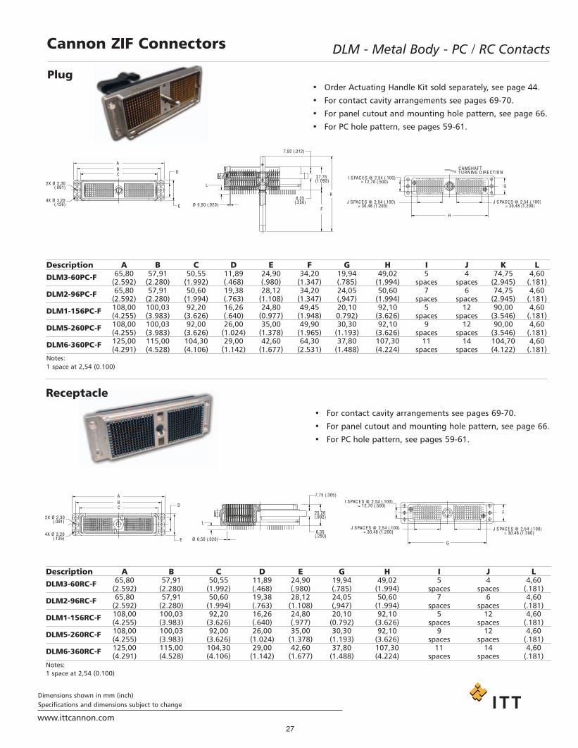
Cannon ZIF Connectors DLM - Metal Body - PC / RC Contacts
Description A B C D E F G H I J K LDLM3-60PC-F 65,80 57,91 50,55 11,89 24,90 34,20 19,94 49,02 5 4 74,75 4,60
(2.592) (2.280) (1.992) (.468) (.980) (1.347) (.785) (1.994) spaces spaces (2.945) (.181)
DLM2-96PC-F 65,80 57,91 50,60 19,38 28,12 34,20 24,05 50,60 7 6 74,75 4,60(2.592) (2.280) (1.994) (.763) (1.108) (1.347) (,947) (1.994) spaces spaces (2.945) (.181)
DLM1-156PC-F 108,00 100,03 92,20 16,26 24,80 49,45 20,10 92,10 5 12 90,00 4,60(4.255) (3.983) (3.626) (.640) (0.977) (1.948) 0.792) (3.626) spaces spaces (3.546) (.181)
DLM5-260PC-F 108,00 100,03 92,00 26,00 35,00 49,90 30,30 92,10 9 12 90,00 4,60(4.255) (3.983) (3.626) (1.024) (1.378) (1.965) (1.193) (3.626) spaces spaces (3.546) (.181)
DLM6-360PC-F 125,00 115,00 104,30 29,00 42,60 64,30 37,80 107,30 11 14 104,70 4,60(4.291) (4.528) (4.106) (1.142) (1.677) (2.531) (1.488) (4.224) spaces spaces (4.122) (.181)
Notes:1 space at 2,54 (0.100)
Description A B C D E G H I J LDLM3-60RC-F 65,80 57,91 50,55 11,89 24,90 19,94 49,02 5 4 4,60
(2.592) (2.280) (1.992) (.468) (.980) (.785) (1.994) spaces spaces (.181)
DLM2-96RC-F 65,80 57,91 50,60 19,38 28,12 24,05 50,60 7 6 4,60(2.592) (2.280) (1.994) (.763) (1.108) (,947) (1.994) spaces spaces (.181)
DLM1-156RC-F 108,00 100,03 92,20 16,26 24,80 20,10 92,10 5 12 4,60(4.255) (3.983) (3.626) (.640) (.977) (0.792) (3.626) spaces spaces (.181)
DLM5-260RC-F 108,00 100,03 92,00 26,00 35,00 30,30 92,10 9 12 4,60(4.255) (3.983) (3.626) (1.024) (1.378) (1.193) (3.626) spaces spaces (.181)
DLM6-360RC-F 125,00 115,00 104,30 29,00 42,60 37,80 107,30 11 14 4,60(4.291) (4.528) (4.106) (1.142) (1.677) (1.488) (4.224) spaces spaces (.181)
Notes:1 space at 2,54 (0.100)
A
C
2X Ø 2,30(.091)
B
4X Ø 3,20(.126)
7,92 (.312)
F
K6,35
(.250)
27,75(1.093)
Ø 0,50 (.020)
L
32
1
A
45
6
BCDEFGHJKLMNS PRU TVWXYZ
A
bc
BCDEFGHJKLMNS PRU TVWXYZbc c
G
H
I SPAC E S @ 2,54 (.100)= 12,70 (.500)
C AMSHAF TTURNING DIRE C TIO N
J SPAC E S @ 2,54 (.100)= 30,48 (1.200)
J SPAC E S @ 2,54 (.100)= 30,48 (1.200)
D
E
2X Ø 2,30(.091)
4X Ø 3,20(.126)
7,75 (.305)
25,20(.992)
6,35(.250)
Ø 0,50 (.020)
ABCDEFGHJKLMN
ABCDEFGHJKLMNS PRU TVWXYZbc a
45
6
12
3
S PRU TVWXYZbc a
I SPAC E S @ 2,54 (.100)= 12,70 (.500)
J SPAC E S @ 2,54 (.100)= 30,48 (1.200)
J SPAC E S @ 2,54 (.100)= 30,48 (1.200)
A
CB
D
E
L
G
F
• Order Actuating Handle Kit sold separately, see page 44.
• For contact cavity arrangements see pages 69-70.
• For panel cutout and mounting hole pattern, see page 66.
• For PC hole pattern, see pages 59-61.
• For contact cavity arrangements see pages 69-70.
• For panel cutout and mounting hole pattern, see page 66.
• For PC hole pattern, see pages 59-61.
Plug
Receptacle
Project1.qxd:Layout 1 11/12/09 2:34 PM Page 27

Dimensions shown in mm (inch)Specifications and dimensions subject to change
www.ittcannon.com28
Cannon ZIF Connectors DLM - Metal Body - Pressfit Contacts
• Order Actuating Handle Kit sold separately, see page 44.
• For contact cavity arrangements see page 61.
• For panel cutout and mounting hole pattern, see page 66.
• For PC hole pattern, see page 62.
• For contact cavity arrangements see page 61
• For panel cutout and mounting hole pattern, see page 66
• For PC hole pattern, see page 62
Plug
Receptacle
Part Number Nomenclature127050-0378 DLM5-260P-PF-F
Part Number Nomenclature127050-0313 DLM5-260R-PF
Project1.qxd:Layout 1 11/12/09 2:34 PM Page 28
Dimensions shown in mm (inch)Specifications and dimensions subject to change
www.ittcannon.com29
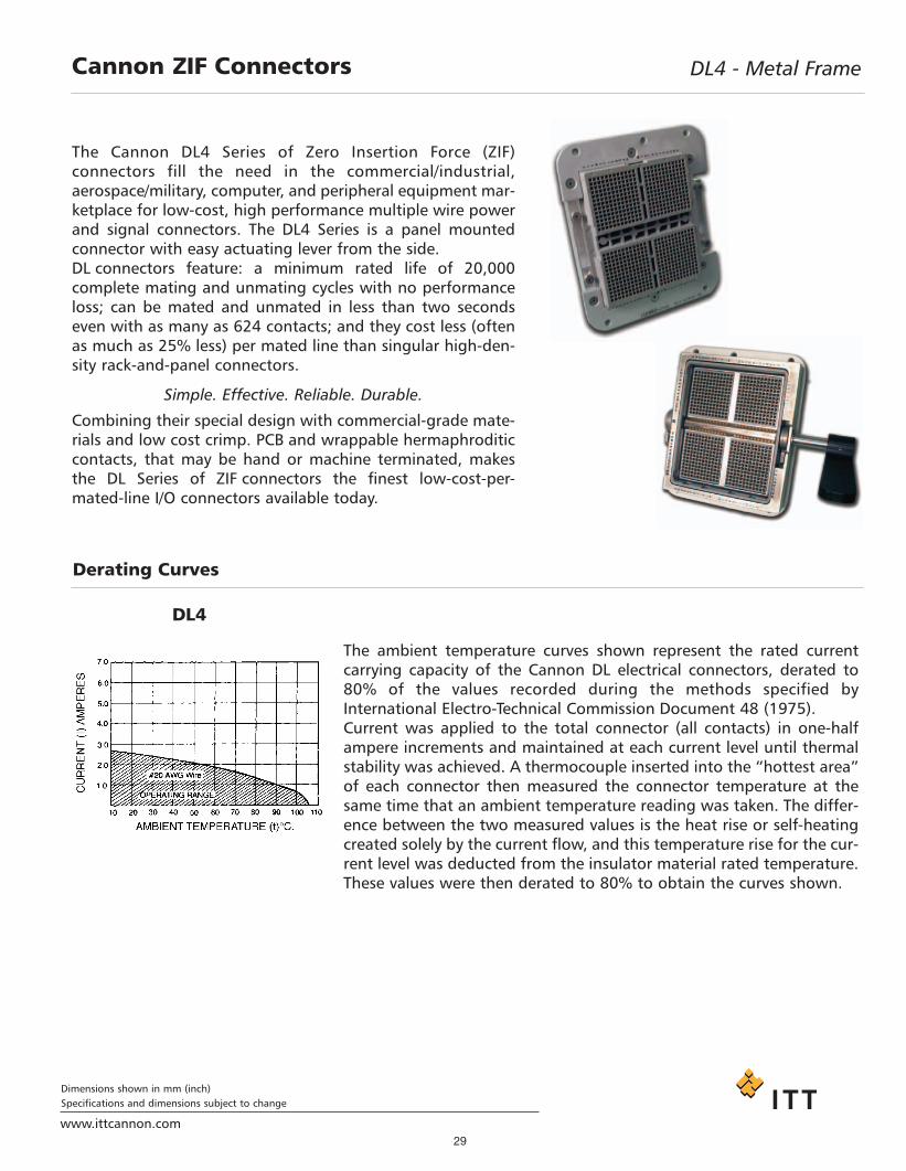
The ambient temperature curves shown represent the rated currentcarrying capacity of the Cannon DL electrical connectors, derated to80% of the values recorded during the methods specified byInternational Electro-Technical Commission Document 48 (1975).Current was applied to the total connector (all contacts) in one-halfampere increments and maintained at each current level until thermalstability was achieved. A thermocouple inserted into the “hottest area”of each connector then measured the connector temperature at thesame time that an ambient temperature reading was taken. The differ-ence between the two measured values is the heat rise or self-heatingcreated solely by the current flow, and this temperature rise for the cur-rent level was deducted from the insulator material rated temperature.These values were then derated to 80% to obtain the curves shown.
Cannon ZIF Connectors DL4 - Metal Frame
The Cannon DL4 Series of Zero Insertion Force (ZIF) connectors fill the need in the commercial/industrial,aerospace/military, computer, and peripheral equipment mar-ketplace for low-cost, high performance multiple wire powerand signal connectors. The DL4 Series is a panel mountedconnector with easy actuating lever from the side.DL connectors feature: a minimum rated life of 20,000 complete mating and unmating cycles with no performanceloss; can be mated and unmated in less than two secondseven with as many as 624 contacts; and they cost less (oftenas much as 25% less) per mated line than singular high-den-sity rack-and-panel connectors.
Simple. Effective. Reliable. Durable.
Combining their special design with commercial-grade mate-rials and low cost crimp. PCB and wrappable hermaphroditiccontacts, that may be hand or machine terminated, makesthe DL Series of ZIF connectors the finest low-cost-per-mated-line I/O connectors available today.
DL4
Derating Curves
Project1.qxd:Layout 1 11/12/09 2:34 PM Page 29
www.ittcannon.com
Dimensions shown in mm (inch)Specifications and dimensions subject to change
30
DL4 - Metal FrameCannon ZIF Connectors
Standard Materials and Finishes
Insulator: Glass filled thermoplastic, UL 94V-1 rated, Color: Black
Housing Frame: Aluminum alloy, nickel plated
Mounting Plate: Aluminum alloy, clear anodized
Crimp Contacts and Copper alloy, 20 or 50 inches gold over 50 inches nickel in mated area,Square Post Contacts: gold flash on balance
Actuating Camshaft: Stainless steel, Passivated
Insulator Retainer(Plug only): Stainless steel, Passivated
Electrical Data
No. of Contacts: 624, 1248*, and 2496* signal
Wire Size: #18 AWG through #42 AWG
Contact Termination: - Crimp- Square Post- Wrap Post- Buss
Mechanical Data
Actuation: Lever
Coupling: Dual Latch
Polarization: -
Contact Spacing: 2,54 (.100) Square Grid
Shell Styles: Plug and Receptacle
Performance Data
Dielectric Withstanding Voltage: 750 VAC RMS - DL4
Insulation Resistance 5000 Megaohms minimum
Durability: 20,000 Cycles minimum
Contact Resistance: - 15 milliohms maximum - Crimp/Square Post Contact- 20 milliohms maximum - Crimp #30- #32 AWG contact
Contact Retention: 8 lb (35,585 N) minimum
* Contact Factory for availability
Project1.qxd:Layout 1 11/12/09 2:34 PM Page 30

31www.ittcannon.com
Dimensions shown in mm (inch)Specifications and dimensions subject to change
DL4 - Metal FrameCannon ZIF Connectors
/ /
DL4 - 624 R
C
SERIES
DL4: Glass filled thermoplas plated aluminium housing frame
CONTACT ARRANGEMENT
624 1248 *
TYPE
P - P lug R - R eceptacle
CONTACT TYPE
No letter - Crimp # 18 thru # 42 AWG TO BE OR DER ED S E P ER ATALY AND INS TALLED BY C US TOMER W4 - Wrap P ost 15,37 (0.605), 20 inches Gold W4A - Wrap Post 15,37 (0.605), 50 inches Gold, P lug only W4B - Wrap Post 15,37 (0.605), 50 inches Gold, R eceptacle only W6 - Square Post 7,11 (0.280), 20 inches Gold W6A - Square Post 7,11 (0.280), 50 inches Gold, P lug only W6B - Square Post 7,11 (0.280), 50 inches Gold, R eceptacle only
W9B - Square Post 3,18 (0.125), 50 inches Gold, Receptacle onlyW9A - Square Post 3,18 (0.125), 50 inches Gold, Plug only
* Contact Factory for availability
2496 *
tic nickel
How to Order
Project1.qxd:Layout 1 11/12/09 2:34 PM Page 31

32www.ittcannon.com
Dimensions shown in mm (inch)Specifications and dimensions subject to change
Cannon ZIF Connectors DL4 - Metal Frame - Crimp Contacts
76,20(3.000)89,28
(3.515)MAX
111,76 (4.400)104,14 (4.100)
MAX
122,44 (4.820)MAX
5X Ø 4,60-4,19(.181-.165)
101,85(4.010)MAX
18,42 (.725)MAX
12,70(.500)
44,45(1.750)
5,08 (.200)9,14 (.360)
4X R 12,70 (.500)
41,40(1.630)
MAX
2,16 (.085)MIN
9,52 (.375)MAX
6,35 (.250)MAX
R 7,62(.300) MAX
20,32 (.800)MAX
3,18 (.125)
10,01 (.394)
R 76,84 (3.025)MAX
R 19,30 (.760)MAX
76,20(3.000)
111,76 (4.400)
122,44 (4.820)MAX
12,70(.500)5X Ø 4,60-4,19
(.181-.165)
101,85(4.010)
MAX
5,08 (.200)
44,45(1.750)
4X R 12,70 (.500)
95,76(3.770)MAX
104,14 (4.100)MAX
9,14 (.360)
21,59 (.850)MAX
9,65 (.380)MAX
3,18 (.125)
Part Number Nomenclature
110959-0002 DL4-624P
Part Number Nomenclature
110960-0002 DL4-624R
• Crimp contacts are to be ordered separately and to be installed by customer, see pages 48-50.
• For contact cavity arrangements see page 70.• For panel cutout and mounting hole pattern, see page 66.
Plug
Receptacle
• Actuating Handles are part of the completed assembly.
• Crimp contacts are to be ordered separately and to be installed by customer, see pages 48-50.
• For contact cavity arrangements see page 70.• For panel cutout and mounting hole pattern, see page 66.
Project1.qxd:Layout 1 11/12/09 2:34 PM Page 32

33www.ittcannon.com
Dimensions shown in mm (inch)Specifications and dimensions subject to change
DL4 - Metal Frame - Square / Wrap Post ContactsCannon ZIF Connectors
76,20(3.000)
89,28(3.515)
MAX
111,76 (4.400)104,14 (4.100)
MAX
122,44 (4.820)MAX
5X Ø 4,52-4,19(.181-.165)
101,85(4.010)
MAX
18,42 (.725)MAX
4X R 12,70 (.500)
9,14 (.360)5,08 (.200)
12,70(.500)
44,45(1.750)
11 SPAC E S @ 2,54 (.100)= 27,94 (1.100)
11 SPAC E S @ 2,54 (.100)= 27,94 (1.100)
66,04(2.600)
2,16 (.085)MIN
41,40(1.630)
MAX
9,52 (.375)MAX
6,35 (.250)MAX
10,01 (.394)
R 7,62(.300) MAX
12 SPAC E S @ 2,54 (.100)= 30,48 (1.200)
12 SPAC E S @ 2,54 (.100)= 30,48 (1.200) 80,64
(3.175)
0,64 (.025)
20,32 (.800)MAX
L 3,18 (.125)
R 19,30 (.760)MAXR 76,84 (3.025)
MAX
76,20(3.000)
101,85(4.010)
MAX
111,76 (4.400)
122,44 (4.820)MAX
12,70(.500)5X Ø 4,60-4,19
(.181-.165)
44,45(1.750)
5,08 (.200)
4X R 12,70 (.500)
95,76(3.770)MAX
11 SPAC E S @ 2,54 (.100)= 27,94 (1.100)
11 SPAC E S @ 2,54 (.100)= 27,94 (1.100)
66,04(2.600)
104,14 (4.100)MAX
12 SPAC E S @ 2,54 (.100)= 30,48 (1.200)
0,64 (.025)12 SPAC E S @ 2,54 (.100)
= 30,48 (1.200)80,64(3.175)
9,65 (.380) MAX
3,18 (.125)
9,14 (.360)21,59 (.850)
MAX
L
Nomenclature L
DL4-624-PW4DL4-624PW4A 15,37 (.605)
DL4-624PW6DL4-624PW6A
7,11 (.280)
DL4-624PW9A 3,18 (.125)Front removable 0,64 (0.025) square posts 2,54 (0.100)Centers.
Plug
Receptacle
Nomenclature L
DL4-624RW4DL4-624RW4A 15,37 (.605)
DL4-624RW6DL4-624RW6A 7,11 (.280)
DL4-624RW9B 3,18 (1.125)Front removable 0,64 (0.025) square posts 2,54 (0.100)Centers
• Actuating handles are part of the completed assembly.
• For contact cavity arrangements see page 70.
• For panel cutout and mounting hole pattern, see page 66.
• For contact cavity arrangement see page 70.
• For panel cutout and mounting hole pattern, see page 66.
Project1.qxd:Layout 1 11/12/09 2:34 PM Page 33

34www.ittcannon.com
Dimensions shown in mm (inch)Specifications and dimensions subject to change
Cannon ZIF Connectors DLP - Metal Shell
Cannon has developed a ‘Resilient Contact’ that provides reliable performance with contact wiping actiondirectly on a PCB pad. A high density contact moduleenables a high pin count connector and flexibility. The nickel plated aluminum housing along withthe embedded grounding springs offer superior perform-ance under the harshest EMI conditions. The DLP, likethat of the DL, is capable of over 10,000 mating cycles. WIth the PCB acting as the mated contacts, electronics can be mounted at the signalsource, thus reducing cross talk and minimizing real-estate. The DLP-408 is offered with mechanical shuttersto meet the IEC requirements for finger protection.
Housing Aluminum Alloy (DLP136, 204, 272). Zinc Alloy (DLP408) Nickel Plated
Actuating Camshaft Stainless Steel, Passivated
Materials and Finishes
Electrical Data
No. of Contacts: 136, 204, 272, 408
Wire Size: N/A
Contact Termination: ReceptacleDIP Soldering to PCB - DLP 136, 204, 272 Pressfit to PCB (408)
PlugCable termination to PCBDirect soldering to daughter board stacked to PCBInterface connector between cable and PCB
Mechanical DataActuation: Single Hand
Coupling: Rotating Latch
Polarization: Polarizing Posts
Contact Spacing: 1.9 (0.075 Pitch (DLP136 204, 272), 1.6 (0.063) Pitch (DLP408)
Shell Styles: Plug and Receptacle
Performance Data
Dielectric Withstanding Voltage: 500 VAC RMS
Insulation Resistance 1000 Megaohms minimumDurability: 10,000 Cycles minimum
Contact Resistance: 30 milliohms maximum (Initial)Contact Retention: 4.9N (1.1 LBS)
Project1.qxd:Layout 1 11/12/09 2:34 PM Page 34

35www.ittcannon.com
Dimensions shown in mm (inch)Specifications and dimensions subject to change
DLP - Metal ShellCannon ZIF Connectors
DLP - 408 - * SERIES
DLP : Metal shell
CONTACT ARRANGEMENT
- P (Plug)- R (Receptacle)
408
P
TYPE AND MODIFICATION CODE
How to Order
SERIESDLP: Metal shell
TYPE
P - PlugR - Receptacle
CONTACT ARRANGEMENT - NUMBEROF CONTACT MODULES - LOCATION DUMMY - MOD. CODE
136 - 4 AB204 - 6 A272 - 8 NONE
DLP R 272 - 8 - *
Project1.qxd:Layout 1 11/12/09 2:34 PM Page 35

Dimensions shown in mm (inch)Specifications and dimensions subject to change
www.ittcannon.com36
DLP - Metal ShellCannon ZIF Connectors
Plug
Receptacle
Part Number Nomenclature127050-0299 DLP-P
Part Number Nomenclature127050-0444 DLP-R204-6-A-F127050-0391 DLP-R272-8-F
• For PC hole pattern, see page 64.
• For contact cavity arrangements, see page 71
• Order Protective cover, sold separately. See page 45.
• For PC pad layout, see page 64.
• Not including backshell, handle, and screw.
• For contact cavity arrangements, see page 71.
Part Number Description127000-2721 DLP PWB Plate 8127000-2721 DLP PWB Plate 6M2.5 x 15mm PWB Plate Mounting Screw
Note: Flat head screw length dependent on customerbackshell design
Project1.qxd:Layout 1 11/12/09 2:34 PM Page 36

Dimensions shown in mm (inch)Specifications and dimensions subject to change
www.ittcannon.com37
Cannon ZIF Connectors DLP - Metal Shell
Part Number Nomenclature
127050-0516 DLP408P127059-0053 PWB Plate Screws (center)*127059-0054 PWB Plate Screws (corners)*** Two Center plate screws required.** Four Corner plate screws required.
Part Number Nomenclature
127050-0452 DLP408R
Plug• Order Actuating Handle Kit, sold separately. See page 44.
• For Contact Cavity arrangements, see page 71.
• For PC pad layout, see page 65.
• PWB Protective Plate included. Screws sold separately.
• For PC hole pattern, see page 65.
• For contact cavity arrangements, see page 71.
Receptacle
Project1.qxd:Layout 1 11/12/09 2:34 PM Page 37

QLCCannon ZIF Connectors
ITT Expands its DL Family of Connectors with theMiniature QLC Device to Meet Size, Reliability, andMating Requirements for Portable Medical EquipmentSimilar to the DL Series connectors, the QLC connectoris highly reliable, easily assembled during harness andmating, and features a high pin count—up to 260 contacts in PC board-mount style. The QLC connectoremploys rugged nickel-plated aluminum housings andfeatures a minimum rated life of 20,000 complete mating cycles with no performance loss. The interfaceof the QLC connector utilizes EMI springs and a shield-locking mechanism to ensure uniform mating pressurearound the perimeter of the mated connector, creatingan EMI/RFI shield.
With technology advances for small portable imaging equipment, the demand for a smaller, higher pin count,shielded, reliable connector proves essential.Consequently, ITT reduced the spacing from the standard DL to 0.8mm, thus reducing the overall size by morethan 60% with the same number of contacts. The high pin count allows the engineer to utilize variousgrounding schemes to maintain signal integrity. The reduction in size, coupled with the superior shield designof the QLC, creates a sound interconnect choice for today’s portable market.
QLC Housing: Zinc, Nickel plated
Contacts: Copper Alloy, 40 inches gold over nickel in mating area, gold flash over nickel in tail area
Shaft Assembly: Stainless steel and plastic
Ground Spring: Stainless steel
Insert Mold: Plastic
Materials and Finishes
Electrical Data
No. of Contacts: 260
Wire Size: N/A
Contact Termination: Receptacle - DIP Solder to PCBPlug - Solder to Daughter Board
Mechanical DataActuation: Roating Handle
Coupling: Quad Latch
Polarization: Polarizing Posts
Contact Spacing: 0.8mm
Shell Styles: Plug and Receptacle
Performance Data
Dielectric Withstanding Voltage: 1000 VAC RMS
Insulation Resistance 1000 Megaohms minimumDurability: 20,000 Cycles maximum
Contact Resistance: 100 milliohms maximum (including bulk resistance)Contact Retention: N/A
www.ittcannon.com38
Dimensions shown in mm (inch)Specifications and dimensions subject to change
Project1.qxd:Layout 1 11/12/09 2:34 PM Page 38

www.ittcannon.com39
Dimensions shown in mm (inch)Specifications and dimensions subject to change
Cannon ZIF Connectors QLC
Plug
Receptacle
Part Number Nomenclature127050-0529 QLC260P127059-0067 Insulator Retaining Screw (2 required)
Part Number Nomenclature127050-0530 QLC260R
• Insulator retaining screw sold separately.
• For PC hole pattern, see page 65.
• Order actuating handle kit, sold separately. See page 44.
• For contact cavity arrangements, see page 71.
• For PC pad layout, see page 65.
Project1.qxd:Layout 1 11/12/09 2:34 PM Page 39

Cannon ZIF Connectors Accessories - Overview
40www.ittcannon.com
Dimensions shown in mm (inch)Specifications and dimensions subject to change
Cannon offers a wide selection of accessoriesthat allow the design engineers to configurethe product for their exact needs. The acces-sories range from the simple actuating handleto junction and backshells, as well as polarizing posts and protective covers for the contacts.
Actuating handles are the same for the DL1/2/3and DLM1/2/3 series. The DL5/DLM5 and DLM6series have specific handles. Handles are soldseparately since many applications require theconnector to be attached or removed only byan authorized technician.
Plastic junction shells are available for theDL1/2/3 series for encasement of the crimp contacts after complete installation into the connector. These shells also make it possible forthe DL to be used as a cable-to-cable mating connector as they can be used both on the plug and the receptacle. The DL1/2/3plastic junction shells have optional secondarycable entry capability by removing the moldingin the cable entry plugs. Cable clamp kits areavailable to affix the cable to the second entry.This second entry option is very useful in applications where the large wire sizes makethe cable diameter too large to be handled from a single entry port.
Metal Backshells are available for the entireDL/DLM series. The metal backshells are constructed from die cast aluminum with anickel plating to facilitate in EMI/RFI shieldingof the connector systems. Shielding hasbecome a driving force because of the everincreasing stringent EMI/RFI regulations
Polarizing posts ar available to offer akeying feature for both the DL andDLM connectors. The polarizing postscan be installed in specific orientationso that plugs of the same size connectors can only be mated in pre-determined receptacles. This featureoffers the designer the ability to fool-proof the attachment possibilities toprotect accidental damage to the system. Protective covers of plasticand anti-static rubber are available to
offer contact protection from physicaldamage or dust. Since the DL series hasa high density of contacts in anexposed area, these covers are very use-ful for many applications. For example,where systems have multiple connec-tors, or when the connections are oftenleft unattached, or when the systemparts are put into storage.
Accessory Selection Guide
Project1.qxd:Layout 1 11/12/09 2:34 PM Page 40

Dimensions shown in mm (inch)Specifications and dimensions subject to change
www.ittcannon.com41
Accessories - Plastic Junction ShellsCannon ZIF Connectors
Product Features• Stainless steel cable clamps• Thermoplastic UL 94V-1 rated• Straight 90 or 45 cable entry
• Accommodates up to 22,22 (.875) cable
• For use with crimp contact connectors• Knockout plug provides alternate second entry• Complete with 4 attaching screws and nuts• Complete with one cable clamp kit
DL1 / DLM1Description Part A B C D E F G H I Max
Number Cable Entry110,74 62,36 68,58 86,36 43,94 57,78 63,50 27,69 50,44(4.360) (2.455) (2.700) (3.400) (1.730) (2.275) (2.500) (1.090) (1.988)MAX MAX MAX MAX MAX MAX MAX MAX MAX
Note: Single Piece Shell
DL-1-J/S 249-1950-00022,23(0.875)
DL2 / DLM2DL3 / DLM3Description Part A B C D E F G H I Max
Number Cable Entry68,83 46,81 52,45 71,04 30,05 36,45 39,29 31,75 44,04(2.710) (1.843) (2.065) (2.797) (1.183) (1.435) (2.500) (1.547) (1.250)MAX MAX MAX MAX MAX MAX MAX MAX MAX68,83 46,81 52,45 71,04 30,05 36,45 39,29 31,75 44,04(2.710) (1.843) (2.065) (2.797) (1.183) (1.435) (2.500) (1.547) (1.250)MAX MAX MAX MAX MAX MAX MAX MAX MAX68,83 46,81 52,45 71,04 30,05 36,45 39,29 31,75 44,04(2.710) (1.843) (2.065) (2.797) (1.183) (1.435) (2.500) (1.547) (1.250)MAX MAX MAX MAX MAX MAX MAX MAX MAX68,83 46,81 52,45 71,04 30,05 36,45 39,29 31,75 44,04(2.710) (1.843) (2.065) (2.797) (1.183) (1.435) (2.500) (1.547) (1.250)MAX MAX MAX MAX MAX MAX MAX MAX MAX68,83 46,81 52,45 71,04 30,05 36,45 39,29 31,75 44,04(2.710) (1.843) (2.065) (2.797) (1.183) (1.435) (2.500) (1.547) (1.250)MAX MAX MAX MAX MAX MAX MAX MAX MAX68,83 46,81 52,45 71,04 30,05 36,45 39,29 31,75 44,04(2.710) (1.843) (2.065) (2.797) (1.183) (1.435) (2.500) (1.547) (1.250)MAX MAX MAX MAX MAX MAX MAX MAX MAX
Note: Two Piece Shell
DL2-J/S 249-1985-000 14,20(0.560)
DL2-2-J/S 249-2238-000 15,90(0.625)
DL2-4-J/S 249-2238-001 22,23(0.875)
DL2-3-J/S 249-2060-00014,20(0560)
DL3-3-J/S 249-2237-00015,90(0.625)
DL3-4-J/S 249-2237-001 22,23(0.875)
DL2 / DLM2DL3 / DLM3Description
PartA B C D E F G H I Max
Number Cable Entry68,83 46,81 52,45 71,04 30,05 36,45 39,29 31,75 44,04
DL2-1-J/S 249-1985-001 (2.710) (1.843) (2.065) (2.797) (1.183) (1.435) (2.500) (1.547) (1.250)15,90
MAX MAX MAX MAX MAX MAX MAX MAX MAX(0.625)
68,83 46,81 52,45 71,04 30,05 36,45 39,29 31,75 44,04DL3-2-J/S 249-2060-001 (2.710) (1.843) (2.065) (2.797) (1.183) (1.435) (2.500) (1.547) (1.250)
15,90
MAX MAX MAX MAX MAX MAX MAX MAX MAX(0.625)
Note: Two Piece Shell
Junction Shell Kit (Straight or 90º Mounting)
Junction Shell Kit (45º Mounting)
Project1.qxd:Layout 1 11/12/09 2:34 PM Page 41

42 www.ittcannon.com
Dimensions shown in mm (inch)Specifications and dimensions subject to change
Accessories - Cable Clamp KitsCannon ZIF Connectors
DL1 / DL2 / DL3
DescriptionPart Max
Number Cable EntryMounting
DL1-C/C 218-0179-00022,23 Straight or 90°(0.875)
DL1-C/C (1) 218-0180-00014,20 Straight or 90°(0.680)
DL2-2-C/C (1) 218-0180-00115,90 Straight or 90°(0.625)
DL2-3-C/C (1) 218-0200-00022,23 Straight or 90°(0.875)
Cable Clamp Kit for optional second entry (Straight or 90º Mounting)
DL2
Description Part MaxNumber Cable Entry
Mounting
DL2-1-C/C (1) 218-0181-000 15,90 45°(0.625)
Note: (1) Also suitable for DL3 Connectors
Cable Clamp Kit for optional second entry (45º Mounting)
Project1.qxd:Layout 1 11/12/09 2:34 PM Page 42

43www.ittcannon.com
Dimensions shown in mm (inch)Specifications and dimensions subject to change
Cannon ZIF Connectors Accessories - Metal Backshells
Standard Materials and FinishesShell: Nickel over die cast aluminum
Hardware: Stainless Steel
Used PartA B C D E F
MaxOn Number Cable Entry
77,8 33,0 65,8 36,3 24,5 28.1DL2 / DLM2 (1) 249-4517-000 (3.06) (1.30) (2.59) (1.43) (.96) (1.11)19,05(0.750)
77,8 33,0 65,8 36,3 24,5 28.1DL3 / DLM3 (1) 249-4518-000 (3.06) (1.30) (2.59) (1.43) (.96) (1.11)19,05(0.750)
Note: Kit consists of 2 shells, 9 screws, 1 wire hood, 1 wire clamp, 1 lock/open indication seal.
Two Piece Shell Design (Straight or 90º Mounting)
One Piece Shell Design (Straight or 90º Mounting)
Used PartA B C D E F
MaxOn Number Cable Entry
123,4 48,6 111,4 N/A 24,0 28,12 19,05DL1/ DLM1 (2) 249-4520-000 (4,86) (1.91) (4.38) (0.945) (1.11) (0.750)49,0 115,8 7,6 30,0 42,6 22,3
DL5/ DLM5 (3) 249-4501-000 N/A (1.93) (4.56) (0,30) (1.18) (1.68) (0.875)63,0 125,0 7,6 30,0 42,6 28,00
DL5/ DLM5 (3) 249-4515-000 N/A (2.48) (4.92) (0,30) (1.18) (1.68) (1.102)Notes: (2) Kit consists of 2 shells, 10 screws, 1 wire hood, 1 wire clamp, 1 lock/open indication seal.
(3) Kit consists of 1 shell, 8 screws, 1 wire hood, 1 wire clamp, 4 nuts.
DL2 / DLM2DL3 / DLM3
DL1/DLM1DL5/DLM5DLM6
Project1.qxd:Layout 1 11/12/09 2:34 PM Page 43
Dimensions shown in mm (inch)Specifications and dimensions subject to change
www.ittcannon.com44
Cannon ZIF Connectors Accessories - Actuating Handle Kits
Product Features
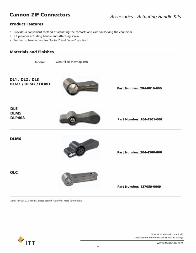
• Provides a convenient method of actuating the contacts and cam for locking the connector.• Kit provides actuating handle and attaching screw.• Pointer on handle denotes “locked” and “open” positions.
Materials and Finishes
Handle: Glass filled thermoplastic
DL1 / DL2 / DL3DLM1 / DLM2 / DLM3
DL5DLM5DLP408
DLM6
Part Number: 204-0016-000
Part Number: 204-4501-000
Part Number: 204-4500-000
QLC
Part Number: 127059-0069
Note: For DLP 272 Handle, please consult factory for more information.
Project1.qxd:Layout 1 11/12/09 2:34 PM Page 44

Dimensions shown in mm (inch)Specifications and dimensions subject to change
www.ittcannon.com45
Accessories - Protective CoversCannon ZIF Connectors
Protective Covers - Plastic
Materials and Finishes
Cover: Polyethylene
Cover for Part NumberDL1-156P 025-0852-000DL2-96P 025-0857-000DL3-60P 025-0850-000
Cover for Part NumberDL1-156R 025-4506-000DL2-96R 025-4505-000DL3-60R 025-4509-000DL5-260R 025-1218-000
DL / DLM Receptacle
DL / DLM Plug
Note: Must remove/cut secondary cap from DL5 cover
Nomenclature Part Number
DLP PWB Protect 6A/H 127000-2721DLP PWB Protect 8 127000-2720DLP Plug Dust Cap 127000-2719DLP Receptacle Dust Cap 127000-2732
DLP 272
Product Features• Fits snugly over mating faces• Prevents foreign matter from permeating contact cavities
Protective Covers - RubberMaterials and Finishes
Cover: Anti-static synthetic rubber
Cover for Part NumberDL1-156P 039-0242-000DL2-96P 039-0244-000DL3-60P 039-0246-000DL4-624P 039-0239-000
DL / DLM Plug
Cover for Part NumberDL1-156R 039-0243-000DL2-96R 039-0245-000DL3-60R 039-0247-000DL4-624R 039-0240-000
DL / DLM Receptacle
Protective Covers
Project1.qxd:Layout 1 11/12/09 2:34 PM Page 45

46www.ittcannon.com
Dimensions shown in mm (inch)Specifications and dimensions subject to change
Accessories - Polarizing PostsCannon ZIF Connectors
Center Mounting
Materials and Finishes
Post: Zinc, copper over nickel
Screw: Stainless Steel
DL1 / DL2DLM1 / DLM2
Corner Mounting
Materials and Finishes
Post: Zinc, nickel
Screw: Stainless Steel
Kit consists of Part Number2 posts and 2 No. 4-40x9/32 320-0021-006
DL1 / DL2 / DL3DLM6
Kit consists of Part Number4 posts and 4 M2.5x10 screws 320-4505-000
DL5DLM5
DLM1 / DLM2 / DLM3
Kit consists of Part Number2 posts and 2 no, 2- 56 X3/16fil. Head screws
320-0021-005
Kit consists of Part Number4 posts and 4 M3x8 screws 320-4502-000
Project1.qxd:Layout 1 11/12/09 2:34 PM Page 46

47
www.ittcannon.com
Dimensions shown in mm (inch)Specifications and dimensions subject to change
Cannon ZIF Connectors Accessories - EMI / RFI Shielding Shells
Materials and Finishes
Shell: Steel, Nickel Finish
Description Part NumberPlug Shell 248-4500-000
Metal Shells (DL5 only)
Plug
Description Part NumberReceptacle Shell 248-4501-000
Receptacle
Project1.qxd:Layout 1 11/12/09 2:34 PM Page 47
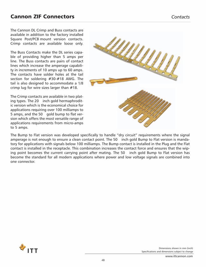
Dimensions shown in mm (inch)Specifications and dimensions subject to change
www.ittcannon.com48
Cannon ZIF Connectors Contacts
The Cannon DL Crimp and Buss contacts areavailable in addition to the factory installedSquare Post/PCB mount version contacts.Crimp contacts are available loose only.
The Buss Contacts make the DL series capa-ble of providing higher than 5 amps perline. The Buss contacts are pairs of contactlines which increase the amperage capabili-ty in increments of 10 amps up to 60 amps.The contacts have solder holes at the tailsection for soldering #30-#18 AWG. Thetail is also designed to accommodate a 1/8crimp lug for wire sizes larger than #18.
The Crimp contacts are available in two plat-ing types. The 20 inch gold hermaphrodit-ic version which is the economical choice forapplications requiring over 100 milliamps to5 amps, and the 50 gold bump to flat ver-sion which offers the most versatile range ofapplications requirements from micro-ampsto 5 amps.
The Bump to Flat version was developed specifically to handle “dry circuit” requirements where the signalamperage is not enough to ensure a clean contact point. The 50 inch gold Bump to Flat version is manda-tory for applications with signals below 100 milliamps. The Bump contact is installed in the Plug and the Flatcontact is installed in the receptacle. This combination increases the contact force and ensures that the wip-ing point becomes the current carrying point after mating. The 50 inch gold Bump to Flat version hasbecome the standard for all modern applications where power and low voltage signals are combined intoone connector.
Project1.qxd:Layout 1 11/12/09 2:34 PM Page 48

Dimensions shown in mm (inch)Specifications and dimensions subject to change
www.ittcannon.com49
Contacts - Buss ContactsCannon ZIF Connectors
• Designed for power distribution of more than 5 amps.• Accommodates #30-#18 AWG in hole ∅ 1,29-1,14
(.051-.045) for wire soldering.• Accommodates 1/8 crimp lugs for larger wire sizes.
Material: Copper Alloy
Finish: 20 inch in mating area / gold flash on balance (terminating end)
Wire Termination - Solder Wire Termination - Crimp Lug
Buss Contact
Description Part Number1 Pair 030-7380-0012 Pair 030-7380-0023 Pair 030-7380-0034 Pair 030-7380-0045 Pair 030-7380-0056 Pair 030-7380-006
Note: For more information on tools and assembly, see pages
Note: Contacts must be installed in the vertical position.
1 Pair
Project1.qxd:Layout 1 11/12/09 2:34 PM Page 49

50www.ittcannon.com
Dimensions shown in mm (inch)Specifications and dimensions subject to change
Contacts - Crimp ContactsCannon ZIF Connectors
• Recommended for all applications• Offer the broadest amperage range• Mandatory for low current applications, less than 100 milliamps.
50 inch Gold Contacts
Materials and Finishes
Material: Copper Alloy
Finish: 50 inch Gold over Nickel in mated area, Gold flash on balance (terminating end)
Wire Loose ReeledType Part Number Part Number
28 thru 32 AWG 030-2416-003 110238-048224 thru 26 AWG 030-2410-003 110238-048020 thru 22 AWG 030-2409-003 110238-047918 thru 20 AWG (1) 030-2415-003 110238-0481
Plug (Bump)
Wire Loose ReeledType Part Number Part Number
28 thru 32 AWG 030-2494-001 110238-048624 thru 26 AWG 030-2492-001 110238-048420 thru 22 AWG 030-2491-001 110238-048318 thru 20 AWG (1) 030-2493-001 110238-0485
Receptacle (Flat)
20 inch Gold Contacts
Materials and Finishes
Material: Copper Alloy
Finish: 20 inch Gold over Nickel, in mated area, Gold flash on balance (terminating end)
Wire Loose ReeledType Part Number Part Number
36 thru 38 AWG (2) 127000-2207 127000-127128 thru 32 AWG 030-2416-005 110238-103024 thru 26 AWG 030-2415-005 110238-102920 thru 22 AWG 030-2410-005 110238-102818 thru 20 AWG 030-2409-005 110238-1027
Plug and Receptacle (Bump) (3)
Note: (1) Non insulation support(2) 20 inch gold in mating area/Gold flash on balance (terminating end), RoHS compliant, sold in lots of 100 pieces.(3) 20 nch gold Bump contact are used for both Plug and Receptacle
Note: Contact can be used in both plug and receptacle for appli-cations above 100 MA.
Caution: Flat contacts can only be used in the receptacle
Project1.qxd:Layout 1 11/12/09 2:34 PM Page 50

51www.ittcannon.com
Dimensions shown in mm (inch)Specifications and dimensions subject to change
Tools and AssemblyCannon ZIF Connectors
A key feature of the Cannon DL connector series iseasy contact termination, both in the field and inhigh-volume production. An ergonomicallydesigned hand crimp tool is available for the lowvolume (loose contact) applications and will accom-modate two different crimp contact sizes. To reduceoverall costs, the crimp jaws are replaceable.
Automatic crimp and strip/crimp machines are avail-able for high volume applications requiring a largenumber of crimps (50,000 crimps per year or more).These machines are leased to customers to eliminatethe need for heavy investment. They also improveproductivity for large pin count applications.
DL Crimp contacts are designed to be hand installedinto the connector, no tooling is needed for theinsertion process. Extraction tools are available forthe removal of Crimp contacts for easy repair even infield applications. Extraction tools are also availablefor the Buss contacts, as well as the factory installedSquare Post contacts.
Crimp tensile strength is a measure ofhow hard a wire can be pulled withoutbreaking or separating from the contact.This is the best way to verify that the wireis properly terminated to the contact.Periodic crimp tensile measurements arerecommended to insure the integrity ofthe crimp. The table below contains theappropriate values for DL crimp contacts.
Hand Crimp Tool
Crimp Tensile Strength
Wire Trim Dimension
Hand Crimp Tool with Replaceable Jaw SetHand Tool Description Part Number
1 CHDLT 28-32 112108-00022 CHDLT 20-26 112108-00013 CHDLT 18-20 112108-0000
Wire Size (AWG) 32 30 28 26 24 22 20 18Tensile Min. (lbs) 1 1.5 3 7 10 15 19 30Wire Trim Dimension “A” 3,30 (.130) 3,30 (.130) 3,30 (.130) 3,30 (.130) 3,30 (.130) 3,30 (.130) 4,06 (.160) 4,06 (.160)Insulation Dia. Max 1,35 (.053) 1,35 (.053) 1,35 (.053) 1,65 (.065) 1,65 (.065) 1,88 (.074) 1,88 (.074) 1,88 (.074)
Project1.qxd:Layout 1 11/12/09 2:34 PM Page 51

Dimensions shown in mm (inch)Specifications and dimensions subject to change
www.ittcannon.com52
Contacts - Crimp Contacts - ReeledCannon ZIF Connectors
Extraction Tool - Crimp, Square Post, PC/RC Contacts
Description Part Number Contact Type PC Tail ExtensionCET-DL10 274-7029-007 Crimp -CET-ECP 274-7045-000 Wrap Post 15,37 (.605)CET-ECP-1 274-7045-001 Square Post 7,11 (.280)
CET-DL10 CET-ECP CET-ECP-1
Extraction Tool for Buss ContactDescription Contacts Part Number
CET-DL3 1 pair 274-7029-003CET-DL4 2 pair 274-7029-004CET-DL4 3 pair 274-7029-004CET-DL5 4 pair 274-7029-005CET-DL6 5 pair 274-7029-006CET-DL6 6 pair 274-7029-006
Extraction Tool - Buss Contacts
Project1.qxd:Layout 1 11/12/09 2:34 PM Page 52

Dimensions shown in mm (inch)Specifications and dimensions subject to change
www.ittcannon.com53
Tools and Assembly - Crimp ContactsCannon ZIF Connectors
Assembly Instructions for Crimp Contacts
Contact Insertion:All crimp contacts inserted by hand. Notooling is required for either the plug orreceptacle.
Caution: Do not force contacts into contact cavities. If contact encountersexcessive resistance during installationremove and re-insert using a slight up anddown motion. This will assure positive cavity alignment. Do not install contact ifplug is in the closed or actuated position.
Plug:Step 1. Prior to inserting contacts, turn theshaft counter-clockwise to its maximumopen position.Step 2. WIth the retention lance positionedaway from the shaft, insert contacts fromthe rear of the contact plug.
Receptacle:
Step 1. With the retention lance positionedtoward the shaft hole, insert contacts fromthe rear of the receptacle.
Contact Removal for Crimp Contacts
Tool: CET-DL10
Release retention lance by inserting tip ofextraction tool into cavity until it bottomson insulator shoulder. Gently pull wire indirection of arrow, see illustration, toremove contact from insulator.
Project1.qxd:Layout 1 11/12/09 2:34 PM Page 53

54www.ittcannon.com
Dimensions shown in mm (inch)Specifications and dimensions subject to change
Cannon ZIF Connectors Tools and Assembly - Buss Contacts
Assembly Instructions for Buss Contacts
Contact Insertion:All buss contacts are inserted by hand. Notooling is required for either the plug orreceptacle.
Caution: Do not force contacts into contact cavities. If contact encountersexcessive resistance during installationremove and re-insert using a slight up anddown motion. This will assure positive cavity alignment. Do not install contact ifplug is in the closed or actuated position.
Plug:Step 1. Prior to inserting contacts, turn theshaft counter-clockwise to its maximumopen position.Step 2. WIth the retention lance positionedaway from the shaft, insert contacts fromthe rear of the contact plug.
Receptacle:
Step 1. With the retention lance positionedtoward the shaft hole, insert contacts fromthe rear of the receptacle.
Contact Removal for Buss Contacts
Tool: CET-DL3/4/5/6
Release retention lance by inserting tip ofextraction tool into cavity until it bottoms oninsulator shoulder. Gently remove buss con-tact in direction of arrow, see illustration, toremove contact from insulator.
Project1.qxd:Layout 1 11/12/09 2:34 PM Page 54

www.ittcannon.com
Dimensions shown in mm (inch)Specifications and dimensions subject to change
55
Cannon ZIF Connectors Tools and Assembly - Square / Wrap Post Contacts
Assembly Instructions for Square Post Contacts
Contact Removal for Square Post Contacts
Project1.qxd:Layout 1 11/12/09 2:35 PM Page 55

Dimensions shown in mm (inch)Specifications and dimensions subject to change
www.ittcannon.com56
Tools and AssemblyCannon ZIF Connectors
Lease Automatic Tooling - North America*
ABT-620 UCCS
The ABT-620 Universal Cannon Crimper /Stripper is a pneumatic powered, microproces-sor controlled machine. It is designed to semi-automatically strip insulation from stranded orsingle conductor electrical wire and attach astamped and formed contact by crimping. Themachine will accommodate 34 thru 12 AWGwire. Primary application of the machine is thetermination of jacketed cable where the individual leads cannot be stripped by fullyautomated equipment. The ABT-620 UCCSoperates automatically upon insertion of a wireor it can be switched over to a foot pedal operation as desired.
Machined Strip / Crimp Rate:1200+ per hour
Power Requirements: Electrical = 115 VAC, 60 Hz, 20APneumatic = 80 psi, 3 cu. ft per min.
* For other geographical regions, contact Cannon for details.
Mini Applicators are interchangeable modulesthat will fit into many standard crimpingmachines. They are available for all sizes ofstamped and reeled contacts
Mini Applicator DL-T 18-20 DL-T 20-22 DL-T 24-26 DL-T 28-32Applicator p/n 112211-0002 112211-0003 112211-0009 112211-0010
Wire Size 18 20 20 22 24 26 28 30 32
Strip Length Reference 4.00 (0.160)
4.00 (0.160)
3.3 (0.130)
3.3(0.130)
3.3(0.130)
3.3 (0.130)
3.3 (0.130)
3.3 (0.130)
3.3 (0.130)
Conductor Crimp Width -Max
1,80(0.071)
1,80(0.071)
1,710(0.067)
1,710(0.067)
1,5(0.059)
1,5(0.059)
1,5(0.059)
1,5(0.059)
1,5(0.059)
Conductor Crimp Height +/- 0,03 (0.001)
1,52(0.060)
1,34(0.053)
1,25(0.049)
1,22(0.048)
1,04(0.041)
0,96(0.038)
0,84(0.033)
0,79(0.031)
0,74(0.029)
Insulation crimp Heigh -Max
N/A N/A 1,88(0.074)
1,88(0.074)
1,65(0.065)
1,65(0.065)
1,35(0.053)
1,35(0.053)
1,35(0.053)
Tensile Pull Minimum(Newtons) 133 (30) 84 (19) 84 (19) 67 (15) 44 (10) 31 (7) 13 (3) 7 (1.5) 4 (1)
Wire Size AWG 18-20 20-22 24-36 28-32
20 inches Gold 110238-0402* 110238-0400 110238-0401 110238-040350 inches Gold (Bump) 110238-0481* 110238-0479 110238-0480 110238-0482
50 inches Gold (Flat) 110238-0485* 110238-0483 110238-0484 110238-0486* Without Insulation support
Project1.qxd:Layout 1 11/12/09 2:35 PM Page 56
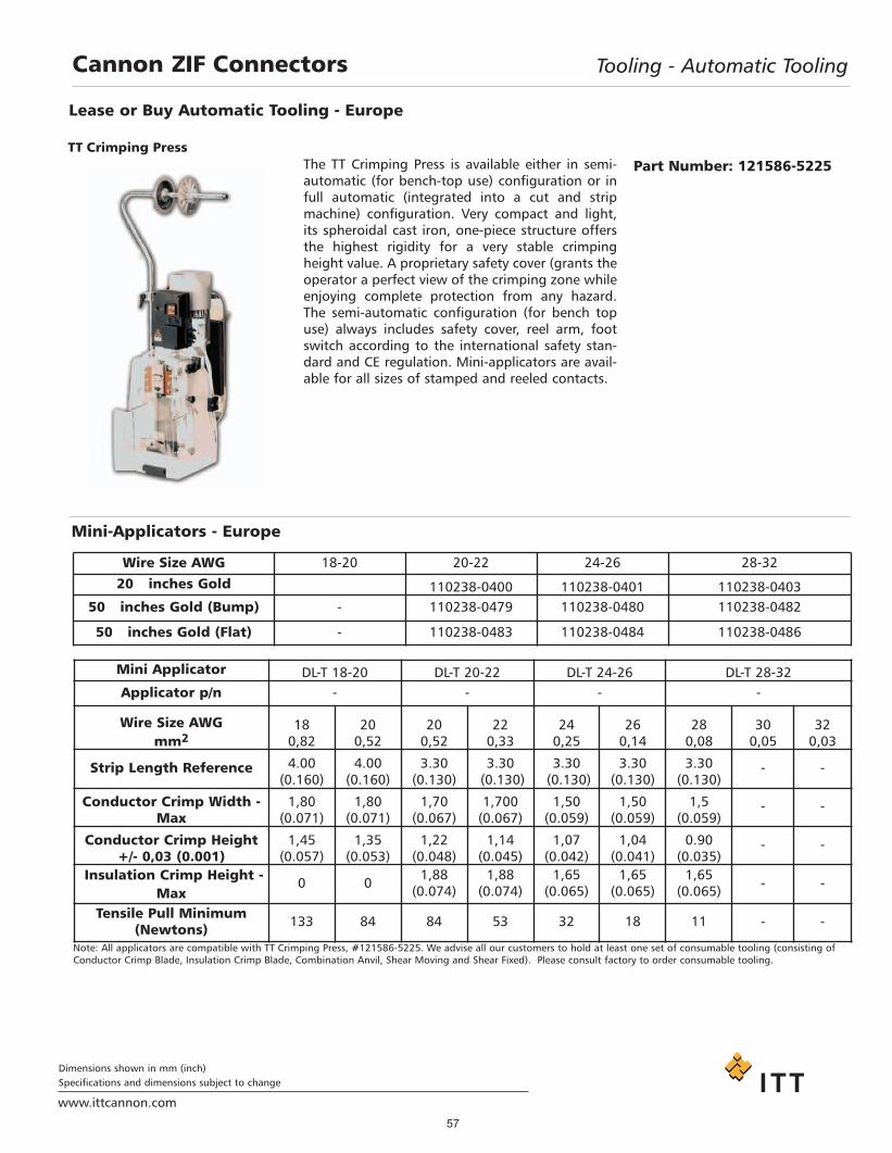
Dimensions shown in mm (inch)Specifications and dimensions subject to change
www.ittcannon.com
57
Cannon ZIF Connectors Tooling - Automatic Tooling
The TT Crimping Press is available either in semi-automatic (for bench-top use) configuration or infull automatic (integrated into a cut and stripmachine) configuration. Very compact and light,its spheroidal cast iron, one-piece structure offersthe highest rigidity for a very stable crimpingheight value. A proprietary safety cover (grants theoperator a perfect view of the crimping zone whileenjoying complete protection from any hazard.The semi-automatic configuration (for bench topuse) always includes safety cover, reel arm, footswitch according to the international safety stan-dard and CE regulation. Mini-applicators are avail-able for all sizes of stamped and reeled contacts.
Lease or Buy Automatic Tooling - Europe
TT Crimping PressPart Number: 121586-5225
Mini-Applicators - Europe
Mini Applicator DL-T 18-20 DL-T 20-22 DL-T 24-26 DL-T 28-32Applicator p/n - - - -
Wire Size AWGmm2
180,82
200,52
200,52
220,33
240,25
260,14
280,08
300,05
320,03
Strip Length Reference 4.00 (0.160)
4.00 (0.160)
3.30 (0.130)
3.30(0.130)
3.30(0.130)
3.30(0.130)
3.30 (0.130)
- -
Conductor Crimp Width -Max
1,80(0.071)
1,80(0.071)
1,70(0.067)
1,700(0.067)
1,50(0.059)
1,50(0.059)
1,5(0.059)
- -
Conductor Crimp Height +/- 0,03 (0.001)
1,45(0.057)
1,35(0.053)
1,22(0.048)
1,14(0.045)
1,07(0.042)
1,04(0.041)
0.90(0.035)
- -
Insulation Crimp Height -Max
0 0 1,88(0.074)
1,88(0.074)
1,65(0.065)
1,65(0.065)
1,65(0.065) - -
Tensile Pull Minimum(Newtons) 133 84 84 53 32 18 11 - -
Wire Size AWG 18-20 20-22 24-26 28-32
20 inches Gold 110238-0400 110238-0401 110238-040350 inches Gold (Bump) - 110238-0479 110238-0480 110238-0482
50 inches Gold (Flat) - 110238-0483 110238-0484 110238-0486
Note: All applicators are compatible with TT Crimping Press, #121586-5225. We advise all our customers to hold at least one set of consumable tooling (consisting ofConductor Crimp Blade, Insulation Crimp Blade, Combination Anvil, Shear Moving and Shear Fixed). Please consult factory to order consumable tooling.
Project1.qxd:Layout 1 11/12/09 2:35 PM Page 57

58
www.ittcannon.com
Dimensions shown in mm (inch)Specifications and dimensions subject to change
Cannon ZIF Connectors PCB Hole Pattern and Pad Layout
PCB Pad Layout
For the PC/RC Versions: The contact tail design has been modified from a 0,64(.025) square pin to a 0,05 (.020) diameter round pin. The change enables adecrease in the diameter of the through holes as well as the solder mounds onPCB’s (d1 and d2 can be wider than D1 and D2). This can reduce the crosstalkin RF circuits and enhance the dielectric withstanding voltage in high voltagecircuits.
The soldering of contacts into through (THRU) holes on a PC Board has becomestandard for medical equipment and test equipment for semi-conductors. As aresult of the narrow spacing between the solder pad and circuit pattern,crosstalk between signals increases. A solution to this problem is to make thediameter of the contacts and solder lands smaller to provide more spacebetween the lands and the patterns. However a smaller diameter contact results in higher impedance.
Cannon designed a solution with a smaller diameter contact tail. This designapplication allows the use of a smaller through-hole diameter.
Project1.qxd:Layout 1 11/12/09 2:35 PM Page 58

59www.ittcannon.com
Dimensions shown in mm (inch)Specifications and dimensions subject to change
Cannon ZIF Connectors PCB Hole Pattern and Pad Layout
DL1 / DLM1 / DLD1 Printed Circuit Board Hole Patterns
Notes:1. Contact hold cavity identifications shown are typical as viewed from top surface of P.C. board.2. All plug layout dimensions not shown are similar to the receptacle dimensions3. Plated through (THRU) hole diameters shown are for 0,64 (.025) post contacts. PC/RC contact plated through (THRU) hole diameters are 0,79 - 0,64(.031-.025). For PCB pad layout configuration see page
Project1.qxd:Layout 1 11/12/09 2:35 PM Page 59

www.ittcannon.com
Dimensions shown in mm (inch)Specifications and dimensions subject to change
Cannon ZIF Connectors PCB Hole Pattern
Notes:1. Contact hold cavity identifications shown are typical as viewed from top surface of P.C. board.2. All plug layout dimensions not shown are similar to the receptacle dimensions3. Plated through (THRU) hole diameters shown are for 0,64 (.025) post contacts. PC/RC contact plated through (THRU) hole diameters are 0,79 - 0,64(.031-.025). For PCB pad layout configuration see page
DL2 / DLM2 / DLD2 Printed Circuit Board Hole Patterns
60
Project1.qxd:Layout 1 11/12/09 2:35 PM Page 60

61www.ittcannon.com
Dimensions shown in mm (inch)Specifications and dimensions subject to change
Cannon ZIF Connectors PCB Hole Pattern and Pad Layout
Notes:1. Contact hold cavity identifications shown are typical as viewed from top surface of P.C. board.2. All plug layout dimensions not shown are similar to the receptacle dimensions3. Plated through (THRU) hole diameters shown are for 0,64 (.025) post contacts. PC/RC contact plated through (THRU) hole diameters are 0,79 - 0,64(.031-.025). For PCB pad layout configuration see page
DL3 / DLM3 / DL5 / DLM5 Printed Circuit Board Hole Patterns
Project1.qxd:Layout 1 11/12/09 2:35 PM Page 61

62www.ittcannon.com
Dimensions shown in mm (inch)Specifications and dimensions subject to change
Cannon ZIF Connectors PCB Hole Pattern and Pad Layout
DLM5 Press-Fit Printed Circuit Board Hole Patterns
Plug
Receptacle
DL5 Plastic Press-Fit (Receptacle only)
Project1.qxd:Layout 1 11/12/09 2:35 PM Page 62

63www.ittcannon.com
Dimensions shown in mm (inch)Specifications and dimensions subject to change
Cannon ZIF Connectors PCB Hole Pattern and Pad Layout
DLM6 Printed Circuit Board Hole Patterns
Notes:1. Contact hold cavity identifications shown are typical as viewed from top surface of P.C. board.2. All plug layout dimensions not shown are similar to the receptacle dimensions3. Plated through (THRU) hole diameters shown are for 0,64 (.025) post contacts. PC/RC contact plated through (THRU) hole diameters are 0,79 - 0,64(.031-.025). For PCB pad layout configuration see page
PlugReceptacle
Project1.qxd:Layout 1 11/12/09 2:35 PM Page 63

64www.ittcannon.com
Dimensions shown in mm (inch)Specifications and dimensions subject to change
Cannon ZIF Connectors PCB Hole Pattern and Pad Layout
DLP-272 Printed Circuit Board Pad Layout
DLP-272 Printed Circuit Board Hole Pattern
Receptacle
Plug
Project1.qxd:Layout 1 11/12/09 2:35 PM Page 64

65www.ittcannon.com
Dimensions shown in mm (inch)Specifications and dimensions subject to change
Cannon ZIF Connectors PCB Pad Layout
DLP 408 Printed Circuit Board Pad Layout / Hole Patterns
ReceptaclePlug
QLC Printed Circuit Board Pad Layout / Hole Patterns
ReceptaclePlug
Note: PWB Pad plating Gold 5 m up over nickel 6 m up
Project1.qxd:Layout 1 11/12/09 2:35 PM Page 65
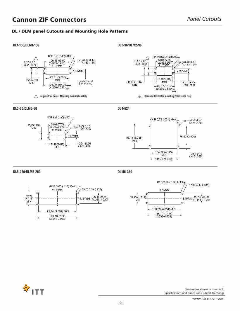
66www.ittcannon.com
Dimensions shown in mm (inch)Specifications and dimensions subject to change
Cannon ZIF Connectors Panel Cutouts
DL / DLM panel Cutouts and Mounting Hole Patterns
Project1.qxd:Layout 1 11/12/09 2:35 PM Page 66
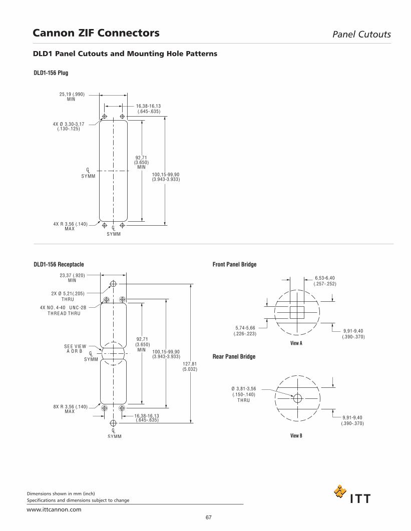
67www.ittcannon.com
Dimensions shown in mm (inch)Specifications and dimensions subject to change
Cannon ZIF Connectors Panel Cutouts
DLD1 Panel Cutouts and Mounting Hole Patterns
Project1.qxd:Layout 1 11/12/09 2:35 PM Page 67

68www.ittcannon.com
Dimensions shown in mm (inch)Specifications and dimensions subject to change
Panel Cutouts
DLD2 Panel Cutouts and Mounting Hole Patterns
Cannon ZIF Connectors
Project1.qxd:Layout 1 11/12/09 2:35 PM Page 68
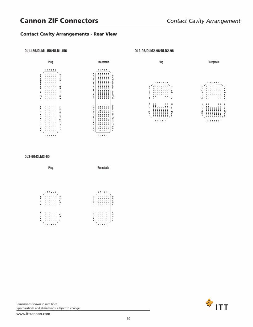
69www.ittcannon.com
Dimensions shown in mm (inch)Specifications and dimensions subject to change
Cannon ZIF Connectors Contact Cavity Arrangement
Contact Cavity Arrangements - Rear View
Project1.qxd:Layout 1 11/12/09 2:35 PM Page 69

70www.ittcannon.com
Dimensions shown in mm (inch)Specifications and dimensions subject to change
Cannon ZIF Connectors Contact Cavity Arrangement
Contact Cavity Arrangements - Rear View
Project1.qxd:Layout 1 11/12/09 2:35 PM Page 70

71www.ittcannon.com
Dimensions shown in mm (inch)Specifications and dimensions subject to change
Cannon ZIF Connectors Contact Cavity Arrangement
Contact Cavity Arrangements
Front View Rear View
Front View Rear View
Front View Rear View
DLP 272
DLP 408
QLC
Project1.qxd:Layout 1 11/12/09 2:35 PM Page 71

72
Appendix
www.ittcannon.com
Cannon ZIF Connectors
DLD Drawer - Assembly Dimensions
DLD Drawer -Mating Sequence
Contacts Aligned Contacts Aligned Contacts Aligned
Shell Size Contact Type A REF B REFDLD1 Crimp 46,86 (1.845) 31,75 (1.250)DLD1 Square Post 57,03 (2.245) 41,91 (1.650)DLD2 Crimp 46,86 (1.845) 31,75 (1.250)DLD2 Square Post 57,03 (2.245) 41,91 (1.650)
The DLD Drawer features ZIF assembly forgreater contact life and eliminates the rodnormally used in such products.
Project1.qxd:Layout 1 11/12/09 2:35 PM Page 72

73www.ittcannon.com
Product Safety InformationCannon ZIF Connectors
11.. MMAATTEERRIIAALL CCOONNTTEENNTT AANNDD PPHHYYSSII--CCAALL FFOORRMMElectrical connectors do not usually containhazardous materials. They contain conduct-ing and non-conducting materials and canbe divided into two groups.a) Printed circuit types and low cost audiotypes which employ all plastic insulators andcasings.b) Rugged, Fire Barrier and High Reliabilitytypes with metal casings and either naturalrubber, synthetic rubber, plastic or glassinsulating materials. Contact materials varywith type of connector and also applicationand are usually manufactured from either:Copper, copper alloys, nickel, alumel,chromel or steel. In special applications,other alloys may be specified.
22.. FFIIRREE CCHHAARRAACCTTEERRIISSTTIICCSS AANNDD EELLEECC--TTRRIICC SSHHOOCCKK HHAAZZAARRDDTThheerree iiss nnoo ffiirree hhaazzaarrdd wwhheenn tthheeccoonnnneeccttoorr iiss ccoorrrreeccttllyy wwiirreedd aanndduusseedd wwiitthhiinn tthhee ssppeecciiffiieedd ppaarraammee--tteerrss.. IInnccoorrrreecctt wwiirriinngg oorr aasssseemmbbllyyooff tthhee ccoonnnneeccttoorr oorr ccaarreelleessss uussee ooffmmeettaall ttoooollss oorr ccoonndduuccttiivvee fflluuiiddss,, oorrttrraannssiitt ddaammaaggee ttoo aannyy ooff tthhee ccoomm--ppoonneenntt ppaarrttss mmaayy ccaauussee eelleeccttrriiccsshhoocckk oorr bbuurrnnss.. LLiivvee cciirrccuuiittss mmuussttnnoott bbee bbrrookkeenn bbyy sseeppaarraattiinngg mmaatteeddccoonnnneeccttoorrss aass tthhiiss mmaayy ccaauussee aarrcc--iinngg,, iioonniizzaattiioonn aanndd bbuurrnniinngg.. Heat dis-sipation is greater at maximum resistance ina circuit. Hot spots may occur when resist-ance is raised locally by damage, e.g. crackedor deformed contacts, broken strands ofwire. Local overheating may also result fromthe use of the incorrect application tools orfrom poor quality soldering or slack screwterminals. Overheating may occur if the rat-ings in the product Data Sheet/Catalog areexceeded and can cause breakdown of insu-lation and hence electric shock. If heating isallowed to continue it intensifies by furtherincreasing the local resistance through lossof temper of spring contacts, formation ofoxide film on contacts and wires and leakagecurrents through carbonization of insulationand tracking paths. Fire can then result inthe presence of combustible materials andthis may release noxious fumes. Overheatingmay not be visually apparent. Burns mayresult from touching overheated compo-nents.33.. HHAANNDDLLIINNGGCare must be taken to avoid damage to any component parts of electrical connec-tors during installation and use. Althoughthere are normally no sharp edges, caremust be taken when handling certain com-ponents to avoid injury to fingers. Electricalconnectors may be damaged in transit to thecustomers, and damage may result in cre-ation of hazards. Products should thereforebe examined prior to installation/use andrejected if found to be damaged.
44.. DDIISSPPOOSSAALLIncineration of certain materials may releasenoxious or even toxic fumes.
55.. AAPPPPLLIICCAATTIIOONNConnectors with exposed contacts shouldnot be selected for use on the current supplyside of an electrical circuit, because an elec-tric shock could result from touchingexposed contacts on an unmated connector.Voltages in excess of 30 V ac or 42.5 V dc arepotentially hazardous and care should betaken to ensure that such voltages cannot betransmitted in any way to exposed metalparts of the connector body. The connectorand wiring should be checked, before mak-ing live, to have no damage to metal parts orinsulators, no solder blobs, loose strands,conducting lubricants, swarf, or any otherundesired conducting particles. Circuitresistance and continuity check should bemade to make certain that there are no highresistance joints or spurious conductingpaths. Always use the correct applicationtools as specified in the Data Sheet/Catalog.Do not permit untrained personnel to wire,assemble or tamper with connectors. Foroperation voltage please see appropriatenational regulations.
IIMMPPOORRTTAANNTT GGEENNEERRAALL IINNFFOORRMMAATTIIOONN((ii )) AAiirr aanndd ccrreeeeppaaggeeppaatthhss//OOppeerraattiinngg vvoollttaaggee.. The admissi-ble operating voltages depend on the indi-vidual applications and the valid nationaland other applicable safety regulations.For this reason the air and creepage pathdata are only reference values. Observereduction of air and creepage paths due toPC board and/or harnessing.
((ii ii)) TTeemmppeerraattuurreeAll information given are temperature limits.The operation temperature depends on theindividual application.
((ii iiii)) OOtthheerr iimmppoorrttaanntt iinnffoorrmmaattiioonnCannon continuously endeavors to improvetheir products. Therefore, Cannon productsmay deviate from the description, technicaldata and shape as shown in this catalog anddata sheets.
ITT Interconnect Solutions, a Division of ITTCorporation manufactures the highest qual-ity products available in the marketplace;however these products are intended to beused in accordance with the specifications inthis publication. Any use or application thatdeviates from the stated operating specifica-tions is not recommended and may beunsafe. No information and data containedin this publication shall be construed to cre-ate any liability on the part of Cannon. Anynew issue of this publication shall automati-cally invalidate and supersede any and all
previous issues.
PPrroodduucctt WWaarrrraannttyyA limited warranty applies to Cannon prod-ucts. In general, except for obligationsassumed by Cannon under this warranty,Cannon shall not be liable for any loss, dam-age, cost of repairs, incidental or consequen-tial damages of any kind, whether or notbased on express or implied warranty, con-tract, negligence or strict liability arising inconnection with the design, manufacture,sale, use or repair of the products. Productavailability, prices and delivery dates areexclusively subject to our respective orderconfirmation form; the same applies toorders based on development samples deliv-ered. Please refer to www.ittcannon.com(General Terms of Sale) for the complete textof Cannon’s applicable Terms andConditions, including Warranty.
This publication is not to be construed as anoffer. It is intended merely as an invitation tomake an offer. By this publication, Cannondoes not assume responsibility or any liabili-ty for any patent infringements or otherrights of third parties which may result fromits use.
Reprinting this publication is generally per-mitted, indicating the source. However,Cannon's prior consent must be obtained inall cases. “Engineered for life” is a registeredtrademark of ITT Corporation ©2006. Allother trademarks or registered trademarksare property of their respective owners. Alldates subject to change without notice.
Commodities in this catalog may be controlled for export by the InternationalTraffic in Arms Regulations (ITAR) and ExportAdministration Regulations (EAR) whenspecifically designed modified, or configuredfor articles controlled by the United StatesGovernment.
Project1.qxd:Layout 1 11/12/09 2:35 PM Page 73

www.ittcannon.com/micro
D-Subminiature Connectors
Rack and Panel Connectors
Microminiature Connectors
Circular/Filter/Hermetic/Fiber Optic Connectors
Initially pioneered by Cannon during the 1930s, InterconnectSolutions is the world leader in rack and panel connectors, offeringunmatched variety of shell configurations and insert arrangements,materials, plating, and contact options. Many of our standard andcustom designs meet the stringent requirements of ARINC 600,ARINC 404 (MIL-C-81659), and MIL-DTL-83733 standards.
As a world leader in circular, filter, and hermetic connectors, ITT canleverage its design and manufacturing expertise to fit virtually anyapplication. Our expertise includes fast positive mating for a widerange of military applications, as well as numerous sizes and contact configurations for various harsh environments. Our widevariety of fiber optic products include hybrid contacts, multi-channel,rack and panel, and hi-rel assemblies, including MIL and ARINCstandard solutions.ITT can meet numerous specs, includingNATO and MIL standards.
Cannon invented D-sub connectors in 1952. Our family of D-Subs now includes combinations of signal, power and RF, aswell as severe service sealed connectors. Cannon D-Subs areavailable with an extensive line of backshells and accessories andare one of the most economical shielded connector solutionsavailable. ITT D-Sub connectors are qualified to the MIL-DTL-24308 specification.
Developed first by Cannon in the 1960’ s, Interconnect Solutionsmicrominiature connectors offer high performance and reliabilitywith exceptional versatility. Available in rectangular, circular,and strip configurations for countless applications, many of ourconnectors meet or exceed applicable requirements of the MIL-DTL-83513 specification.
www.ittcannon.com/rackandpanel
RF ConnectorsITT Interconnect Solutions has been providing interconnect products to the Microwave and RF industry since 1963 (formerlyThe Sealectro Corporation). The RF 50 & 75 Ohm product linescover UHF band through Ku band requirements. These connectorsand cable assemblies are available with a thread type, snap type,bayonet type or slide on coupling method. The frequencies rangefrom DC to 18+ GHz.
www.ittcannon.com/RF50 • www.ittcannon.com/RF75
www.ittcannon.com/circulars • www.ittcannon.com/filter • www.ittcannon.com/hermetics • www.ittcannon.com/fiberoptics
www.ittcannon.com/dsubs
TransportationThe ITT ICS interconnect range includes sealed circular and rectangularconnectors in metal or plastic shells. These configurations include board tocable or cable to cable/ bulkhead applications. Both signal and power con-tacts can be combined in various layouts. All product lines within theTransportation segment offer very low contact resistance providing maxi-mum signal integrity.
www.ittcannon.com/transportation
ITT Interconnect Solutions is an international manufacturer and supplier of connectorsincluding circular, rectangular, fiber optic, RF, power and high voltage, audio, PMCIA,Compact Flash Card, enclosures, cable assemblies, and application specific customsolutions. The Interconnect Solutions portfolio includes the brands Cannon, VEAM, andBIW. As a worldwide leader in connector technology for nearly a century, ITT offers oneof the broadest product offerings, six sigma manufacturing capability, Value BasedProduct Development with exceptional engineering capability, and an extensive sales,distribution, and customer support network.
Project1.qxd:Layout 1 11/12/09 2:35 PM Page 74

Customer Support Locations
CHINATuopandun Industrial Area, Jinda Cheng,Xiner Village, Shajing Town,Baoan District, Shenzhen City,Guangdong, China 518125Phone: +86.755.2726.7238Fax: +86.755.2726.7515
GERMANYCannonstrasse 1Weinstadt, 71384phone: +49.7151.699.0fax: +49.7151.699.217
FRANCE15, Boulevard Robert ThiboustSerris, France 77700phone: +33.1.60.04.93.93fax: +33.1.60.04.93.90
HONG KONGUnits 2405-6, 24/F, ING Tower308 Des Voeux RoadCentralHong Kongphone: +852.2732.2720fax: +852.2732.2919
ITALYCorso Europa 41/43Lainate (MI), Italy 20020phone: +39.02938721fax: +39.0293872300
JAPAN11-3, 5 Chome, Hibarigaoka, Zama-shiKanagawa, Japan 228-0003phone: +52.631.311.0050fax: + 52.631.314.0060
UKJays Close, Viables EstateBasingstoke, RG22 4BAphone: +44.1256.311200fax: +44.1256.323356
USA666 East Dyer RoadSanta Ana, CA 92705toll free: 1.800.854.3028phone: 1.714.557.4700fax: 1.714.628.2142
www.ittcannon.com
©2009 ITT Corporation. “ITT,” “Engineered for Life,” the ITT Engineered Blocks Logo,“Cannon,” “BIW Connector Systems,” and “VEAM” are trademarks of ITT Corporation.Specification and other data are based on information available at the time of printing,and are subject to change without notice.
Space Connectors January 2009
www.ittcannon.com/circulars • www.ittcannon.com/filter • www.ittcannon.com/hermetics • www.ittcannon.com/fiberoptics
Project1.qxd:Layout 1 11/12/09 2:35 PM Page 75