lav ria wat r istri t op rations manualclaveriacagayanwaterdistrict.gov.ph/wp-content/... ·...
TRANSCRIPT

CLAVERIA WATER DISTRICT
OPERATIONS MANUAL
TECHNICAL SERVICES

2 | P a g e C W D O p e r a t i o n s M a n u a l
OPERATING PROCEDURE
Management procedures are documented manuals of actions to be taken when the
system is operating under normal conditions and incident situations. Operational procedures
are usually step-by-step actions to be applied as standard operating procedures in any
circumstances or events. It is also routine good practices aimed to improved present set-ups
in order to achieve a more reliable, efficient and economy-wise solutions to persistent
problems in the water system.
This chapter provides reference on the daily operations of the water district.
Basically, the daily operation of the Claveria Water District is consisting of Water Production
and Distribution, Administrative and Financial Aspects and Commercial Operations.
1. Water Production and Distribution
The Claveria Water District (CWD primary concern is the operation and maintenance
of the pump equipment, repair of pipe service connections, leakages, defective meters,
installation of service connections and the maintenance of water sources and reservoir tank.
The pump motors are mostly operating 24hours. The water is pumped directly into
the water distribution system and excess goes directly to the reservoir tank. The CWD
personnel conducts cleaning operations of the distribution and transmission lines, as well as
the flushing of water through the hydrants, blow-off valves and flushing points to remove
undesirable elements that are accumulated during low pressure and power interruption.
A. Wells
1. Pumping Tests
A pumping test is a field experiment in which a well is pumped at a controlled
rate and water-level response (drawdown) is measured in one or more surrounding
observation wells and optionally in the pumped well (control well) itself; response
data from pumping tests are used to estimate the hydraulic properties of aquifers,
evaluate well performance and identify aquifer boundaries. Aquifer test and aquifer
performance test (APT) are alternate designations for a pumping test.
The pumping test is actually done by the well drilling contractors who are
knowledgeable and who possess the required tools and equipment for the tests. It
only becomes necessary for the water district to conduct the test for monitoring
purposes. Once the pumping level is established, it should be compared with the
design pump curves of the equipment to be used. This will guide the operational
parameters for pumping water from well. The importance and vital nature of the work
of professional well drillers is underscored by the NWRB, which imposes standards
for their activities, regulating and requiring registering with it.

3 | P a g e C W D O p e r a t i o n s M a n u a l
24 Hours Constant Rate Pumping Test Procedure
I. Required Tools and Equipment
- Pumping unit (submersible pump with a capacity greater than the yield
requirement by at least 20%)
- Water Level Indicator
- Stopwatch
- Containers for volumetric measurement of discharge
II. Terminologies
Static Water Level- The vertical distance from ground level (or known
measuring point) to the water surface point in the well during pumping
Pumping Water Level- The vertical distance from ground level (or known
measuring point) to the water surface in the well during pumping
Drawdown- The difference between the pumping water level and the static
water level
Well Yield- The volume of water per unit time that could be pumped from the
well as determined by the pumping test.
III. Discharge Measurements
Discharge measurements are usually measured by a flow meter. If
there is no device to measure the flow, then volumetric measurements will be
resorted to.
The volumetric method consists of noting down the time required to fill
a container (bucket or a drum). Better results are obtained with a larger
container. For more accurate results, several trial measurements should be
done and the average of these trials taken.
IV. Procedure
1. Prior to starting pump, measure and record the static water level.
2. After starting the pump, measure the corresponding water levels.
Discharge should be greater than the required yield and should be
maintained at a constant rate during the entire duration of the test for 24
hours.
Measurement intervals should be as follows:
Time from start of pumping
(min)
Time intervals between
measurements (min)
0-15 0.5-1
10-15 1
15-60 5
60-300 30
300- end of test 60

4 | P a g e C W D O p e r a t i o n s M a n u a l
3. Simultaneous with the water level measurements, take measurements of
discharged.
4. Monitor nearby wells to determine effects during pumping.
5. Right after the end of the pumping test, measure the water level recovery
6. Plot data obtained from the test on a semi-logarithmic paper showing the
time in the abscissa (x-axis) and the drawdown in the ordinate axis (y
axis).
2. Major Causes of deteriorating Well Performance
At the outset, in designing and constructing a well, care should be
taken to prevent the major causes of eventual well deterioration. Following
are five of the main causes of deterioration in well performance. Consider that
the first four of these major causes of well deterioration are greatly influenced
by the care taken in constructing the well.
2.1 Well yield reduction due to the incrustation and growth of iron bacteria;
2.2 Plugging of well screen due to buildup of fine particles;
2.3 Sand Pumping;
2.4 Structural collapse of the well casing and screen; and
2.5 Condition of the pump.
3. Prevention and Remedial Causes
a. Prevention and Treatment of Iron Bacteria
1. Care should be taken to avoid introducing iron bacteria into the well
during drilling and repair work. For this purpose, equipment and
materials (drill rods, filter pack) should be chlorinated prior to drilling or
repair;
2. Chemical treatment (application of strong oxidizing agent such as
chlorine and chlorine compounds) to clear contaminating bacteria; and
3. Physical treatment (jetting, air or surge block surging, air lift pumping)
to clear blockages.
B. Pump in General
1. Manufacturers Recommendations
Pump manufacturers always provide a manual for the operation and
maintenance of their pumps. The instructions in these manuals, including the
recommended maintenance schedule, should be followed.
If during inspection a defect is found, it should be repaired immediately. The
operator should pay attention even to small defects, and not wait for them to worsen,
5 | P a g e C W D O p e r a t i o n s M a n u a l
as these could cause other parts or units to fail, resulting in larger damage and more
costly repairs.
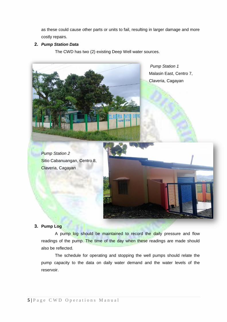
2. Pump Station Data
The CWD has two (2) existing Deep Well water sources.
Pump Station 1
Malasin East, Centro 7,
Claveria, Cagayan
Pump Station 2
Sitio Cabanuangan, Centro 8,
Claveria, Cagayan
3. Pump Log
A pump log should be maintained to record the daily pressure and flow
readings of the pump. The time of the day when these readings are made should
also be reflected.
The schedule for operating and stopping the well pumps should relate the
pump capacity to the data on daily water demand and the water levels of the
reservoir.
6 | P a g e C W D O p e r a t i o n s M a n u a l
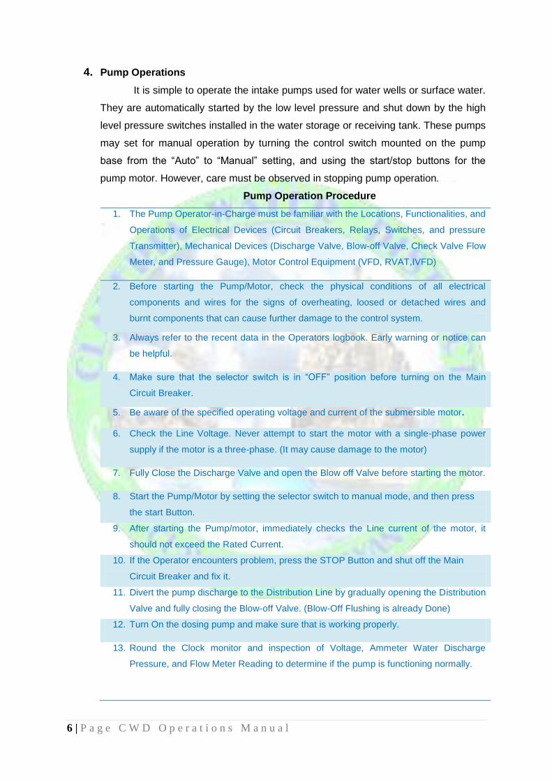
4. Pump Operations
It is simple to operate the intake pumps used for water wells or surface water.
They are automatically started by the low level pressure and shut down by the high
level pressure switches installed in the water storage or receiving tank. These pumps
may set for manual operation by turning the control switch mounted on the pump
base from the “Auto” to “Manual” setting, and using the start/stop buttons for the
pump motor. However, care must be observed in stopping pump operation.
Pump Operation Procedure
1. The Pump Operator-in-Charge must be familiar with the Locations, Functionalities, and
Operations of Electrical Devices (Circuit Breakers, Relays, Switches, and pressure
Transmitter), Mechanical Devices (Discharge Valve, Blow-off Valve, Check Valve Flow
Meter, and Pressure Gauge), Motor Control Equipment (VFD, RVAT,IVFD)
2. Before starting the Pump/Motor, check the physical conditions of all electrical
components and wires for the signs of overheating, loosed or detached wires and
burnt components that can cause further damage to the control system.
3. Always refer to the recent data in the Operators logbook. Early warning or notice can
be helpful.
4. Make sure that the selector switch is in “OFF” position before turning on the Main
Circuit Breaker.
5. Be aware of the specified operating voltage and current of the submersible motor.
6. Check the Line Voltage. Never attempt to start the motor with a single-phase power
supply if the motor is a three-phase. (It may cause damage to the motor)
7. Fully Close the Discharge Valve and open the Blow off Valve before starting the motor.
8. Start the Pump/Motor by setting the selector switch to manual mode, and then press
the start Button.
9. After starting the Pump/motor, immediately checks the Line current of the motor, it
should not exceed the Rated Current.
10. If the Operator encounters problem, press the STOP Button and shut off the Main
Circuit Breaker and fix it.
11. Divert the pump discharge to the Distribution Line by gradually opening the Distribution
Valve and fully closing the Blow-off Valve. (Blow-Off Flushing is already Done)
12. Turn On the dosing pump and make sure that is working properly.
13. Round the Clock monitor and inspection of Voltage, Ammeter Water Discharge
Pressure, and Flow Meter Reading to determine if the pump is functioning normally.

7 | P a g e C W D O p e r a t i o n s M a n u a l
14. Frequent and accurate recording of Line Voltage, Line Current, KWHR Reading,
Discharged Capacity , pressure and Flow Meter Reading. Always examine and
analyze if these valves are in accordance with normal operation.
15. Record in the logbook all the important and events relevant to the smooth and efficient
operation to b endorse to the next operator.
16. Operators are duty-bound to maintain cleanliness and orderliness inside and outside
water pumping station premises.
17. Stop the Pump Operation as per required pump schedule.
18. Press the STOP Button to stop the Pump/Motor.
19. Fully Close the Discharge Valve right after the Pump/Motor stops.
20. Record all the important Data, Time, KWHR Reading, Flow Meter Reading, Motor
Running Hour, and Engine Hour and pressure Reading when the Pump/Motor stops.
21. Turn OFF the Main Circuit Breaker at the Main Control Panel.
22. On-Time Submission of Reports (Monthly Production and Flushing Report).
Standard Operating Procedures for Standby Generator Sets
Standby generator sets are used specifically during power outages and
interruptions; therefore proper handling and maintenance are required in every
operator to ensure that generator sets are always in running conditions as follows:
1. Before starting the generator set, be sure to check the following:
a. Engine Oil Level
b. Radiator Fluid (Coolant/ Water)
c. Fuel Level
d. Battery Condition
e. Air Cleaner
2. Upon starting the generator set, observe the sound that produce by the
generator set during “No load” condition, immediately report to the authorized
mechanic if you hear unusual sound, like “cranking” sound.
3. Before shifting the power to generator set, measure or read the following:
a. Line Voltage Output
b. Frequency
4. Regular warm-up (5minutes) for at least twice a week is also necessary to
prevent clogging to the fuel and also re-charge the battery.
5. Record the latest change oil date which serve as reference to the next one
(every 500 running-hours for brand new gen-set and 300 running –hours for
others).
6. Always maintain minimum fifty percent (50% fuel levels of fuel tank.

8 | P a g e C W D O p e r a t i o n s M a n u a l
5. Pump Trouble Checklist
The manufacturer or supplier of the pump always provides the pump design
curve which is the basic reference for evaluating actual performance. In addition to
the comparison of actual performance against the design curve, the operator should
be alert to the following indications of pump problems:
1. Excessive heating of the motor;
2. Change in the bearing noise level;
3. Change in the pattern of oil consumption of the motor;
4. Excessive vibration;
5. Change in amperage or voltage load;
6. Cavitation noise or other unusual noise; and
7. Presence of cracks or uneven settlement of the pad or ground around
the pump.
Repair and Maintenance of Dosing Pump
1. The Water Resources Operator B will verify and check the brand, date of
purchased (CWD Property Sticker) and operation condition of the dosing
pump.
2. Check every day if the whole system is working from the current source to the
dosing pump to the injection point.
3. Monitor the design strokes of the dosing pump.
4. Check if there is leak and clogging in the system (pump, hose and injector).
5. Referring to previous records of cleaning of pumps, injector valve, and
replacement of delivery tube must be adopted in that pumping station
depending of what kind of disinfectant being used.
6. Always provide a stock of spare dosing pump, repair kit and delivery tube to
avoid any stoppage of operation.
Repair and Maintenance of Pump House and Security Fence
1. Inspect all structure in the pumping station and record all defects to be
address.
2. Repair all deteriorating parts of the structure to ensure its soundness and
beauty.
3. Repaint the structure if necessary.
4. Restore immediately of any damage after calamities.
5. Maintain cleanliness of surroundings and beautify the area

9 | P a g e C W D O p e r a t i o n s M a n u a l
Security Measures of Pumping Station Facilities
1. Secure all gates and equipment rooms with heavy-duty padlocks and overhead
barbwires to all perimeter fences.
2. Ensure all perimeter lights “On” during night time.
3. Daily checking and inventory of all pumping station facilities and equipment.
4. Secure all well opening with threaded caps to prevent contamination from all
sorts (physical, chemical and bacteriological).
5. Every site, visit, inspection and educational trips should be properly documented
and coordinated with concerned personnel.
6. Secure all maintenance tools, materials and machine use during and after
preventive maintenance activities.
7. Only authorized personnel are allowed to enter Water Pumping Stations and
premises.
8. Always use protective gear during and after preventive maintenance activities
and during preparation of chlorine solution and during disinfection.
C. Chlorine Disinfection
This section details the procedures for using chlorine safely as a disinfectant
and the methods of calculating the chlorine dosages required in the water system.
1. General
Disinfection is necessary to ensure that drinking water is free from disease-
causing microorganisms. Water disinfection means the removal, deactivation or
killing of pathogenic (Disease causing microorganisms, such as bacteria, fungi and
viruses) microorganisms. Disinfection is often universally employed by water
distribution systems, even when water at the source is deemed already potable- as
precautionary measure to control the spread of waterborne diseases. In Local Water
Districts, this precautionary is particularly important because of the risk of
contamination due to breaks and other types of seepages anywhere throughout the
extensive pipe network, and the magnified impact of this risk due to the number of
users.
2. Chlorination
Chlorination is the process of adding the element chlorine to water to make it
safe for human consumption as drinking water. Chlorine (and its compound) is the
most widely used disinfectant for water systems because of its effectiveness, cheap
cost and availability.
Chlorination has the advantage of oxidizing bacteria and viruses even after
the point of application due to its residual action. Hence any bacteria introduced to
the system after the point of chlorination can still be eliminated by the residual
chlorine in the water.

10 | P a g e C W D O p e r a t i o n s M a n u a l
Chlorinating Procedures for CWD Production Wells passing the PNSDW
Limits:
c. Chlorine Dioxide Disinfectant
1. 500 grams (1 pack) of Dioxide is dissolved in a fifty (50) liters container of clean
water.
2. Prepared solution must stir thoroughly until particulates are dissolved.
3. Dosing pump foot-valve must have to be suspended a few inches from the
bottom of the container.
4. Dosing pump strokes and adjustments varies on each particular well based on
chlorine residual measurements taken from starting point, midpoints and
endpoints of distribution lines.
d. Calcium Hypochlorite
1. 750 grams of Calcium Hypochlorite is poured in 10liter pail of clean water and
stirred vigorously and letting particulates settled at the bottom.
2. The cleared aqueous solution is to be transferred to a 50 liter container and filled
for until partly full.
3. Dosing pump foot-valve must have to be suspended a few inches from the
bottom of the container.
4. Dosing pump strokes and adjustments varies on each particular well based on
chlorine residual measurements taken from starting point, midpoints and
endpoints of distribution lines.
5. Decanted calcium hypochlorite un-dissolved particulates are to be dispose
properly.
3. Determinants of Chlorine Effectiveness
1. Contact Time (CT & Dosage) - refers to the period of time allowed for the
disinfectant to react with the microorganisms that may be in the water. Dosage
refers to the amount of chlorine in relation to the volume of the water being
treated.
2. The Type of Microorganism – Chlorine is quite effective in destroying the most
significant pathogenic organisms that are dangerous to humans and are
commonly borne in water. Different pathogens and parasites, however, have
different levels of resistance to it. Thus the dosages, the CT, and other conditions
of the water that intensify or inhibit the oxidizing action of chlorine such as
temperature and pH (acidity or alkalinity) need to be considered in order to be
sure that the harmful organisms and undesirable substances are eliminated.
3. Characteristics of the Source Water – The nature of the water that requires
treatment influences the disinfection. Materials in the water, for example, iron,
manganese, hydrogen sulfide and nitrates often react with disinfectants,
effectively increasing the chlorine demand. Turbidity of the water also reduces

11 | P a g e C W D O p e r a t i o n s M a n u a l
the effectiveness of disinfection. Usually, the tests on the water from new source
are the basis for prescribing the dosage and CT needed to eliminate the harmful
and undesirable substances. Additional tests on the water at source need to be
conducted when there are indications that the source water have changed. The
possibility of contaminants (whether pathogens or minerals that change its acidity
or turbidity) in the path of the water or in the proximity of the spring box or
reservoir needed to be checked.
4. Temperature of Water – Higher temperatures usually increase the speed of
reactions and of disinfection.
4. Terminology and Definitions
1. Available Chlorine Content – is amount of chlorine in a chlorine compound, which
determines its potential disinfecting power.
2. Chlorine Demand – is the total amount of chlorine needed to oxidize all the
materials in the water that react with chlorine within a given period. After all the
reactions within that period are completed, the pathogens and undesirable
organic substances, as well as the soluble iron, manganese and hydrogen
sulfides are deemed to have been destroyed, neutralized, or eliminated. Chlorine
demand is the difference between the amount of chlorine added to water and the
amount of residual (remaining) chlorine at the end of a specific contact period. If
no residual chlorine is detected, it means that the chlorine demand was so great
it exhausted the chlorine; thus the chlorine infused into the water (dosage) was
insufficient.
3. Chlorine Residual - the total amount of chlorine (combined and free available
chlorine) remaining in water at the end of a specific contact period following the
infusion of chlorine. The chlorine residual is an important indicator of safe water
because as long as the residual chlorine is present in the water disinfection is
continuing process.
4. Dosage of Chlorine – the quantity of chlorine applied to a specific quantity of
water. Dosage is expressed in milligrams per liter (mg/l) of chlorine.
5. Dosage Rate – is the amount of chlorine applied per unit time. It is usually in
grams/day or kg/day.
6. Super chlorination –this means applying the chlorine at very higher than the usual
dosages. If a system design or requirements do not allow adequate contact time
for the normal dosages of chlorine to eliminate the pathogens and undesirable
substances in the water, super chlorination could be resorted to. Super
chlorination provides a chlorine residual of 3.0-5.0 mg/l, which is 10 times the

12 | P a g e C W D O p e r a t i o n s M a n u a l
recommended minimum breakpoint chlorine concentration. (Breakpoint
chlorination uses the continual addition of chlorine to the water to the point where
chlorine demand is met and all ammonia is oxidized, so that only free chlorine
remains) Retention time for super chlorination is approximately 5 minutes.
7. Dechlorination – removes excessive levels of chlorine from the water.
Dechlorination is considered necessary phase after super chlorination in order to
remove the odor, taste and the other objectionable traces of excess chlorine in
the water. Dechlorination commonly involves the use of an activated carbon filter.
8. Shock Chlorination (dosage of 200 mg/l for 3-4 hours) is recommended whenever
a well, reservoir or pipeline is new, repaired, or found to be contaminated. This
treatment introduces high levels of chlorine to the water. Unlike super
chlorination, shock chlorination is one time only occurrence, and chlorine is
depleted as water flows or is flushed through the system. If bacteriological
problems persists the following shock chlorination, the source of the
contamination of the system should be determined and eliminated.
5. Chlorine Dosages
The commonly used dosages for various disinfection requirements are as
follows:
1. For disinfection of water supplies:
Dosage: 0.5 – 2.0 mg/l
Contact Time: 24-30 minutes
2. For disinfection of newly constructed/ repaired wells, storage tanks, pipelines:
Dosage: 50 mg/l
Contact Time: 24 hours or
6. Measuring Chlorine Residual
CWD checks and maintains
chlorine residuals throughout its water
system to ensure that any
microorganism entering the system
through cross connection will be
killed automatically. The water district
maintains chlorine residuals set in the
Philippine National Standards of Drinking
Water (PNSDW) with values ranging from
1.5 ppm at the pump station to 0.3 ppm at critical
points in the distribution system such as but not limited to dead-end. As part of the

13 | P a g e C W D O p e r a t i o n s M a n u a l
routine water quality maintenance procedures, the CWD takes readings of chlorine
residuals at different distribution points using the Comparator Test Kit.
Measuring Chlorine Residual using Comparator Test Kit
1. Fill a viewing tube with 5 ml sample water and place this tube in the top left opening
of the comparator;
2. Fill a second viewing tube with 5 ml sample water;
3. Add 5 drops of the Orthotolidine Solution (yellow cover) to the yellow test tube;
4. Place the tube to the comparator, and hold up to a light source (sky, window or
lamp);
5. Compare the color of the water to the provided test points (the comparison must be
done one within one minute after adding the solution)
6. If the result is above or below the set (as per DOH Administrative Order No. 2017-
0010), it is needed to lessen or add Chlorine to the water.
7. Water Quality
One of the standards established by Local Water Utilities Administration
(LWUA) for compliance by Local Water Districts, pursuant to Section 62 of PD 198,
as amended, is the regular monitoring of the water quality in terms of bacteriological,
chemical and physical parameters including uniform testing procedures and
submission of water analysis result. It is mandatory for this water to meet at least the
minimum standards specified by the PNSDW. The CWD is doing the best to perform
the regular monitoring to maintain water quality conforming to standards.
a. Bacteriological Water
Analysis
It is a method of analyzing water to
estimate the numbers of bacteria
present and, if needed, to find out
what sort of bacteria they are.
Water samples from various water
sources are examined in the
laboratory facilities of Metro
Tuguegarao Water District (MTWD) or Ilocos Norte Water District (INWD).
When a sample test positive for coli forms, immediately a re-sampling is done
and, without waiting for the results, take the actions needed to determine the
possible source of contamination in order to eliminate the cause.

14 | P a g e C W D O p e r a t i o n s M a n u a l
Sampling points include the pumping stations, reservoir and
concessionaires taps. Sampling is done based on the population served by
the District:
Population
Served
Minimum Frequency of
Sampling for Total Coliform and
Thermotolerant Coliform/ E. coli
Minimum Frequency of
Sampling for Heterotrophic
Plate Count
Less than
5,000
2 samples monthly 2 samples monthly
5,000 –
100,000
1 sample per 5, 000 population
+2 additional samples monthly
1 sample per 5, 000 population
+2 additional samples monthly
More than 100,
000
1 sample per 100, 000
population + 12 additional
samples monthly
Required at least 40% of the
sampling points
Methods of Detection and Standard Values Being Observed
Parameters Method of Determination PNSDW Limit
Total Coliform Multiple Tube Fermentation Technique <1.1 mpn / 100mL
Fecal Coliform Multiple Tube Fermentation Technique <1.1 mpn / 100mL
Heterotrophic
Plate Count Pour Plate Method <500 CFU/ mL
Water Sample Collection for Bacteriological Test
1. The sampling bottle should be kept unopened until the moment it is filled. Care
must be exercised to take samples that will we representative of the water being
used and tested and to avoid contamination of the sample at the time of collection
and in the period before examination;
2. Flame the tap for 2 to 3 months;
3. Open the tap fully allow the water to run to waste for 2 to 3 minutes;
4. Restrict the flow from the tap to one that will permit filling the bottle without
splashing;
5. Hold the bottle near the base, remove the cover and head as a unit, taking care to
avoid soiling;
6. Do not rinse the bottle. Fill it just below the neck to provide ample air space for
mixing purposes;
7. Replace the cap immediately and secure the hood around the neck of the bottle;
8. Submit the water sample immediately after collection to MTWD or INWD within six
(6) hours accompanied by complete and accurate identifying and descriptive data.
9. The use of iced coolers for storage of water samples during transport to laboratory
is must. The bottles with water sample for testing should not have a direct contact to
the water of the storage box.

15 | P a g e C W D O p e r a t i o n s M a n u a l
b. Physical and Chemical Quality Analysis
The Physical and Chemical Analysis is administered annually by the
Platinum Research Laboratory Inc. Although water samples shows presence
of manganese, iron and problems in color, odor and turbidity, it is still within
the permissible limits by the PNSDW.
The required water to be analysed is one (1) liter in every pump station.
Sample containers must be carefully cleaned to remove all extraneous
surface dirt, thoroughly rinsed with distilled water and drained before use.
Date and Time of Sampling, Source of Sample and Name of collector must be
provided in the container.
D. Distribution System
The purpose of distribution system is to deliver water to consumer with
appropriate quality, quantity and pressure. Distribution system is used to describe
collectively the facilities used to supply water from its source to the point of usage.
The distribution system is directed at the following general objectives:
To ensure adequate pressure in the system 24/7
To minimize Non-Revenue Water (NRW);
To ensure that the delivered water is potable
The Distribution System consists of four (4) components, whose operation
and maintenance are based on their unique characteristics as well as their function
and contribution to the total system. They are:
a. Distribution Pipelines
- A water pipe is any pipe or tube designed to transport treated drinking
water to consumers. The varieties include large
diameter main pipes, which supply entire
towns, smaller branch lines that supply a
street or group of buildings, or small
diameter pipes located within individual
buildings.
The distribution pipeline of CWD has about
17.417km of piping with pipe diameters ranging
50mm to 200mm. The pipe materials are Cast Iron (CI)
and Unplastic Poly Vinyl Chloride (uPVC) pipe class 100 and High Density
Poly Ethylene (HDPE) SDR 11.

16 | P a g e C W D O p e r a t i o n s M a n u a l
Water Distribution Lines per Kilometer per Pipe Diameter Size
Pipe Diameter Pipe Material Length
50mm uPVC Pipe 8.231 km
75mm uPVC Pipe 4.944 km
100mm uPVC Pipe 1.519 km
150mm uPVC Pipe 1.548 km
200mm Steel Coated 1.175 KM
Transmission and Distribution Lines Leak Repair
1. Verify and inspect the service request received from the commercial division its
truthfulness and its condition.
2. Prepare the necessary tools or equipment needed to address the repair.
3. If the site condition is a concrete road/sidewalk, prepare the concrete saw for
square holing, jackhammer with compressor for concrete breaking and dewatering
pump for water draining; if it is an ordinary soil use common excavation tools.
4. Inform the public before closing the gate valves of the affected area. Provide
necessary early warning device to avoid accident.
5. In the excavation process, it needs care to avoid damage in the pipeline and
continuous dewatering to avoid intrusion of contaminants inside the pipeline.
6. After repair work is done, open gate valves and proceed to flushing activity to the
nearest flushing point until the water clears.
7. Upon build-up of pressure in the system, observe the repaired portion of the
pipeline if there is a leak. If none, restore the affected area to its original condition.
In backfilling, use other backfill materials if necessary and always compact layer by
layer about 20 cm thick.
8. Fix the warning devices before leaving the area.
Operation and Maintenance of Distribution System (Fire Hydrant, Blow-Off Assembly,
Pipelines and Valves)
1. Only designated personnel (Pump Operators) and BFP (Bureau of Fire Protection)
are authorized for the usage of fire hydrants and blow-off points during flushing
activities and fire events, respectively.
2. Limit or suspend all flushing activities during low water pressure situations,
especially during power outages and interruptions.
3. Conduct flushing activities right after the commercial power resumes eliminating
effects or varying water pressure.
4. Strictly follow all regulars flushing intervals and schedules for every area.
5. Do not leave valve fully open or fully close, but back of 1 ½ turns.
6. Clean valve box and clear hydrant surroundings.
7. Inspect operability of air release valves, special valves.
8. All exposed pipes and mechanical fittings should be inspected for deterioration due
to corrosion or rusting.
9. Replace all malfunction/leaking valves and repaint all exposed pipes and fittings to
weather once a year to avoid rusting.

17 | P a g e C W D O p e r a t i o n s M a n u a l
Fire Fighting Facilities
Hydrant Type Number Location Status
Angle Hydrant-150mm 3 Centro 2, Centro 4 Operational
Angle Hydrant-100mm 8 Centro 1, Centro 2,
Centro 3, Centro 4,
Centro 5, Centro 6,
Centro 7, Centro 8
Operational
b. Storage Tank or Reservoir
Water for distribution is
pumped from the water source to the
system’s water tank or reservoir, from
which it is delivered to the consumers
through the pipelines. The reservoir is
designed, based on the requirements
of the system, to distribute the water
by pumping.
Operation and Maintenance of Elevated Water Reservoir
1. Ensure security of the utility entry point and opening of reservoir.
2. Daily checking of water level of reservoirs.
3. Weekly collection of raw and treated water samples for presence/absence of
coliforms and chlorine residual analysis.
4. Observe for crack/leaks and implement repair the soonest
5. Strictly implement periodic cleaning and maintenance of reservoir inner chamber
as per schedule.
6. Keep reservoir roof ladders free of dirt, debris or grease to prevent slipping
contamination.
7. Never enter a closed reservoir alone without someone standing by to help you in
trouble.
8. Complete cleaning and disinfection are recommended.

18 | P a g e C W D O p e r a t i o n s M a n u a l
Cleaning of Reservoir
The quality of water coming from the reservoir must be maintained
within the standards for potable water. To ensure the quality of water supply,
the reservoir of the District is annually cleaned and disinfected to avoid
accumulation of solids and proliferation of bacteria in the tank, making unsafe
for drinking.
1. Scheduling of date of Cleaning. Coordination with the CAGELCO II
regarding their schedules of power interruption to avoid same day of service
interruption, communicating to schools and cooperatives if they had
programs and activities in the tentative dates of cleaning.
2. Preparation of water service interruption advisory, and distribution of
notices, posting at the District’s Website
(claveriacagayanwaterdistrict.gov.ph), Facebook Page
(https://www.facebook.com/Claveria-Water-District-Cagayan-Valley-Region-
02), and airing at Claveria Radio Station, and TV (via Agri-based Cable TV).
3. Preparation of materials to be used.
4. Hiring of laborers to do the cleaning.
5. Stoppage of pumping operations and draining the reservoir.
6. The cleaning proper.
7. Filling up of the tank then flushing twice to wash the cleaned reservoir.
8. Flushing of distribution end points.
9. Back to normal operation.
c. Service Connections
A pipeline or lateral tap at the Water District mains leading to an
individual household with provisions of water meter, outlet, valve and meter
stand. The systematic inspection and replacement of consumption meters is
an important aspect of routine maintenance. Representative pothole checking
of service connections within 5 years of service (avoid leaks due to
deterioration) should also be done. The water service connection is a small
water pipe connecting the distribution water main to residential, commercial or
industrial buildings. The District
takes responsibility of leakages
from the main lines up to the water
meter while concessionaires is from
the “after the meter” up to inside of
his house.
19 | P a g e C W D O p e r a t i o n s M a n u a l
Operation and Maintenance of Service Connections and Meters
1. Follow established installation procedure for new connection
2. All service connection pipes should be embedded to prevent potential
damage due to exposure
3. Repair of all service connections leaks should be accomplished immediately
to minimize NRW (Non-Revenue Water) and increase Water System
Pressure
4. Maintain accuracy of all water meters by regular maintenance and periodic
cleaning
5. Replacement of water meters should be done every five years
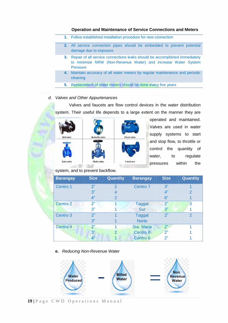
d. Valves and Other Appurtenances
Valves and faucets are flow control devices in the water distribution
system. Their useful life depends to a large extent on the manner they are
operated and maintained.
Valves are used in water
supply systems to start
and stop flow, to throttle or
control the quantity of
water, to regulate
pressures within the
system, and to prevent backflow.
Barangay Size Quantity Barangay Size Quantity
Centro 1 2”
3”
4”
2
4
2
Centro 7 3”
4”
6”
1
2
1
Centro 2 2”
3”
1
1
Taggat
Sur
2”
3”
3
1
Centro 3 2”
3”
1
1
Taggat
Norte
2” 2
Centro 4 2”
3”
4”
1
2
1
Sta. Maria
Centro 8
Centro 6
2”
2”
2”
1
1
1
e. Reducing Non-Revenue Water

20 | P a g e C W D O p e r a t i o n s M a n u a l
Non-Revenue Water (NRW) is water that has been produced but does not
result in revenue for the District. NRW is a result of leaks and wastage, meter
inaccuracies and sometimes theft. NRW is typically measured as the volume of water
“lost” as a share of net water produced.
NRW can be analyzed on whether they are physical or actual losses due to
commercial policies or deficiencies:
a. Physical Losses
Leaks/ Breaks
Illegal Connections
Water Usage by the District (Flushing, etc.)
b. Commercial Losses
Non-metered connections
Under-registration of meters
Poor collection performance
Performance audit to water meters being used by customers to ensure
accuracy is being done; defective water meters are immediately attended to minimize
revenue losses; and distribution Pipes/Lines are being monitored. These routines are
conducted periodically to maintain and even decrease the percentage of the Non-
Revenue Water.
The percentage of NRW can be determined by the formula:
NRW (%) =
Production (m³) - Billed Consumption (m³) x 100
Production (m³)
FABRICATION SHOP
The CWD has different kinds of Maintenance equipment which usually they
fabricate it in our store room which is under our reservoir tanks.
Hand Tools
Welding Machine
Air Compressor
Battery Charger
Portable Grinder
Electric Grill
The Agency acquired different units of equipment generator sets and 1 motor service vehicle that are used for the operation of the district, to wit;
TMX Single Motor Submersible Pump Motor
40 KVA Generator Set: Isuzu (4JB1) Portable Motor Pump
25KVA Generator Set: Denyo Portable Generator Set

21 | P a g e C W D O p e r a t i o n s M a n u a l