latamchilechina - oko association
DESCRIPTION
LATAMCHILECHINA, ha concretado una Alianza Estratégica con OKO ASSOCIATION, entidad de origen Ucraniano, con el propósito de llevar adelante la Difusión, Comercialización y Distribución de sus productos en el Mercado Chileno y Latinoamericano, siendo LATAMCHILECHINA quien estará facilitando la gestión de importación de los interesados en estos productos. Las empresas asociadas a OKO ASSOCIATION, están especializadas en la producción de equipos para la inspección de Pruebas No Destructivas, de equipos críticos, de distintos rubros industriales, tales como, calderas de agua, vapor, recipientes a presión, tubería de agua caliente, grúas, depósitos de petróleo y productos derivados del petróleo, oleoductos y equipamientos tecnológicos de procesamiento de gas, petroquímica y química.TRANSCRIPT

"OKOASSOCIATION"
Ukrainian scientific research institute for
non-destructive testing
"Ultracon-Service"
"Promprylad"
NNOONN--
DDEESSTT
RRUUCCTT
IIVVEE
TTEESSTT
IINNGG

OK
O A
SSO
CIA
TIO
N
"Promprylad"P.O.Box 43, Kiev 080, Ukraine,tel./fax: (044)467-51-38(39),E-mail:[email protected] www.promprilad.com.ua
Operating frequency range _ _ _ _ _ _ _ _ _ _ _ _ _ _ _ _ _ _ _ _ _ _from 0,4 to 15 MHzInspection range (in steel) _ _ _ _ _ _ _ _ _ _ _ _ _ _ _ _ _ _ _ _ _ _ _ _ _ _ _0…6000 mmGain dynamic range _ _ _ _ _ _ _ _ _ _ _ _ _ _ _ _ _ _ _ _ _ _ _ _ _ _ _ _ _ _ _ _ _ _100 dBAbsolute error when measuring the Hx flaw depth _ _ _ _ _ _ _ _ _ _ _ _ _ _ _ _ _ _ _ _ _ _ _ _ _ _±(0,1+0,005 Hx) mmAbsolute error when measuring the Nx signal amplitudes ratio _ _ _ _ _ _ _ _ _ _ _ _ _ _ _ _ _ _ _ _± (0,2+0,03 Nx) dBWeight, up to _ _ _ _ _ _ _ _ _ _ _ _ _ _ _ _ _ _ _ _ _ _ _ _ _ _ _ _ _ _ _ _ _ _ _ _ _ _0,8 kgDimensions _ _ _ _ _ _ _ _ _ _ _ _ _ _ _ _ _ _ _ _ _ _ _ _ _ _ _ _ _ _ _105 x 190 x 80 mm
IS INTENDED FOR:• Discontinuities and irregularities detections
in materials, items, semi-products, welded and soldered joints;
• Flaw depth and coordinates measurement;• Echo-signals amplitudes ratio measurement;• Defect equivalent size measurement;• Item thickness measurement;• Sound velocity measurement;• Defect equivalent and conditional sizes measurement;MAIN FEATURES:• All thickness gauge functions;• A - scan and B - scan;• Rectifier: RF/full wave/+ half wave/- half wave;• Gain control function set, including AGC, TCG;• Automatic probe and test piece parameters calibration interface;• Several DGS diagrams operating modes;• Two independent tree-level measuring gates;• Coupling control system;• Flaw detection alarm system on all gate's levels;• Bright three-color alarm LEDs;• Advanced peak curve mode;• Mode of current signal overlaying an earlier frozen one ("freeze and live" mode);• Dynamic control of the pulser parameters depending on the probe frequency;• Reflections highlight mode;• Special program interface option;• "User", "Expert" menu modes;• Results and settings storage;• Communication with PC via USB port.
BASIC TECHNICAL CHARACTERISTICS:
Ultrasonic Flaw Detector - ThicknessGauge UD3-71UD3-71
3

"OK
O A
SS
OC
IAT
ION
"
"Promprylad"P.O.Box 43, Kiev 080, Ukraine,
tel./fax: (044)467-51-38(39),E-mail:[email protected]
www.promprilad.com.ua
4
GENERAL FEATURES
U L T R A S O N I C F L A W D E T E C T O R
U D 4 - 7 6U D 4 - 7 6
Operating frequency range _ _ _ _ _ _ _ _ _ _ _ _ _ _ _ _ _ _ _ _from 0,4 to 15MHzInspection range (in steel) _ _ _ _ _ _ _ _ _ _ _ _ _ _ _ _ _ _ _ _ _ _ _0…12 000 mmGain dynamic range _ _ _ _ _ _ _ _ _ _ _ _ _ _ _ _ _ _ _ _ _ _ _ _ _ _ _ _ _ _ _100 dBAbsolute error when measuring the Hx flaw depth _ _ _ _ _ _ _ _ _ _ _ _ _ _ _ _ _ _ _ _ _ _ _ _±(0,1+0,005 Hx) mmAbsolute error when measuring the Nx signal amplitudes ratio _ _ _ _ _ _ _ _ _ _ _ _ _ _ _ _ _ _±(0,2+0,03 Nx) dBDimensions (without handle) _ _ _ _ _ _ _ _ _ _ _ _ _ _ _ _ _ _ _ _247x147x80 mm
Weight, up to _ _ _ _ _ _ _ _ _ _ _ _ _ _ _ _ _ _ _ _ _ _ _ _ _ _ _3,5 kg
• Operating with any type of piezo-electric transducers;
• Defect equivalent and conditionalsizes measurement;
• Thickness measurement;• A - scan and B - scan;• Synchronization: internal, exter-
nal, from coder;• Scanning speed control;• Rectifier: RF/full wave/+ half
wave/- half wave;• Gain control function set, includ-
ing AGC, TCG;• Automatic probe and test piece
parameters calibration interface;• Several DGS diagrams operating
modes;
BASIC TECHNICAL SPECIFICATIONS:
Is intended for manual and mechanized ultrasonictesting of materials, items, products
and equipment; acquiring and saving tomograms.
• Two independent tree-level meas-uring gates;
• Two more special gates;• Coupling control system;• Flaw detection alarm system on all
gate's levels;• Bright three-color alarm LEDs;• Advanced peak curve mode;• Mode of current signal overlaying
an earlier frozen one ("freeze andlive" mode);
• Signals spectrum display;• Dynamic control of the pulser
parameters depending on theprobe frequency;
• Reflections highlight mode;• "User", "Expert" menu modes;• Voice comments recording
referred to all data types;• Large, high contrast TFT display;• Results and settings storage;• Communication with PC via USB
port.

"OK
O A
SS
OC
IAT
ION
"
"Promprylad"P.O.Box 43, Kiev 080, Ukraine,tel./fax: (044)467-51-38(39),E-mail:[email protected] www.promprilad.com.ua
5
Fast ultrasonic, eddy-current and complex testingof products and equipment
•Real - time processing, saving and visualization of the testing results;•100% testing process and results registration;•Flexible hardware configuration allows to build the testing systemwith required number of ultrasonic or eddy-current channels;•Operation with remotely controlled and manual scanners;•2 coder inputs;•Replaceable compact flash card for instrument software and data storage;•Possibility of specialized software development in conformity with any testing task;•Number of UT channels: 8/16/24/32 - depending on user requirements;•Number of ET channels: up to 128 - depending on user requirements;•All ensonification schemes realization in manual or automatic modes (UT);
INFORMATION REPRESENTATION:
1. A-scan (UT)2. B-scan (UT)3. Orthogonal views (UT)4. Signals imaging on a complex plane (ET)5. Bar diagram (ET)6. Vector presentation (ET)7. Triggered sweep (ET)8. C-scan (ET)9. Gain dynamic range: 0 - 80 dB (UT) / 0 - 65 dB (ET) with 1 dB step;
10. Digital filters can be selected according to a testing task (UT, ET);
11. Creation of signals mixtures (ET);12. Multi-channel, multi-frequency testing (ET);13. ET channels frequency range: 100 Hz - 2 MHz.
UNIVERSAL FLAWDETECTOR OKO - 01OKO - 01(ultrasonic and eddy - current options)

"OK
O A
SS
OC
IAT
ION
"
"Promprylad"P.O.Box 43, Kiev 080, Ukraine,
tel./fax: (044)467-51-38(39),E-mail:[email protected]
www.promprilad.com.ua
6
EDDY-CURRENTFLAW DETECTOR
VD3 - 71VD3 - 71Universal portable eddy-current flaw detector is a solu-
tion for a variety of eddy-current testing tasks:
• Welded joints testing;• Acceptance testing of pipes, rods, wires, bars, etc;
• Testing of power generating equipment elements including heat exchangers
with encircling coil probes;• Acceptance and in service testing of vehicles;
• Tanks and vessels testing in chemicals, oil-and-gas and other industry branches;
• Usage of different probe types;• Multi-frequency (2 frequencies) testing;• Signal imaging on the complex plane
(signal hodograph), signal vector imaging, signal time function representation;
• 5 algorithms of signals mixing from 2 channels;• Signal phase correction;
• Automatic measurement of signal's amplitude and phase;
• Evaluation of defect size (in millimeters, % of wall thickness, etc) in accordance with selected or recorded calibration curve;
• Digital filtering - 5 types of filters: low-frequency, high-frequency, band-pass, differential, averaging;
• Intellectual signal scaling; • Recording and storage of up to 100 flaw detector settings sets;
• Recording and storage of up to 100 testing results depending on testing duration;
• Communication with PC through the USB port; • LED’s and sound flaw alarm system;
• Headphones output; • Color high-resolution high-contrast TFT-display;
• Ergonomic case; • Integrated accumulator power supply;
• Intellectual charging device in delivery set.
Operating frequency range _ _ _ _ _ _ _ _ _ _ _ _ _ _from 500 Hz to 6 MHzGenerator output voltage _ _ _ _ _ _ _ _ _ _ _ _ _ _ _ _ _ _ _from 0,5 to 8 VGain setting range _ _ _ _ _ _ _ _ _ _ _ _ _ _ _ _ _ _ _ _ _ _ _ _ _ _ _ _52 dBSignals scaling range _ _ _ _ _ _ _ _ _ _ _ _ _ _ _ _ _ _ _ _ _ _ _ _ _ _0,1…10Sampling frequency _ _ _ _ _ _ _ _ _ _ _ _ _ _ _ _ _ _to 3000 samples/sec.
BASIC TECHNICAL CHARACTERISTICS:

"OK
O A
SS
OC
IAT
ION
"
"Promprylad"P.O.Box 43, Kiev 080, Ukraine,tel./fax: (044)467-51-38(39),E-mail:[email protected] www.promprilad.com.ua
7
INFORMATION REPRESENTATION:• A-scan (UT)• Orthogonal views (UT)• B-scan (UT)• Thickness map
EDDY-CURRENT OPTION
• Signal display:• XY/ YT/ XT/ V - one-channel mode• MULTY / 2D - multi-channel• Signal digital processing:
1. mixing2. filtration
• Possibility of 16 exterior modules input: one-channel, multi-channel, specialized;• Eddy-current channels frequency range: 500 Hz - 6 MHz;• External synchronization.
BASIC FUNCTIONALITIES:
• Large, high contrast color TFT display;• Flaw detection alarm system: 16 bright three-color LED's, alarm system;• Options convenient control with the help of handle;• Operation with different scanners;• Possibility of audio comments creation to all the types of saved data;• Communication with computer network Ethernet;• Possibility of keyboard and mouse PS/2 input;• USB 2.0. maintenance.
ULTRASONIC OPTION• 5 coders inputs;• Software realization in different testing tasks: ring welded joints testing, rolled products testing; • All ensonification schemes realization in manual or automatic modes (UT);• Rectifier: RF/full wave/+ half wave/- half wave; creeping wave;• Dynamic characteristics change of gain depending onfrequency filters;• Possibility of module input for phased array operating.
MULTI-CHANNELFLAW DETECTORSOKO-2OKO-2

TDM-1 TDM-2• Measurement results correction + +
according to probe's space position (00, 450, 900, 1350, 1800) (00, 900,1800)• Calibration option + +• Statistic measurement mode + (from 3 to 99) + (3 and 5)• Automatic translation of hardness
to the ultimate tensile strength (according to GOST 22761); + —• Battery discharge level control + +• Automatic alarm system of measured sound
value overrunning the user preset limits and visual visual• Measurement results storage + (2000) —• Communication with PC through
RS232 port; testing report generation option + —• Non-stop operating time with full batteries, at least 1 hour 25 25• Operating temperatures range — 10…+ 40 0С — 20…+ 50 0С• Case protection level according to GOST 14254 IP40 IP65• Electronic unit dimensions 158 х 85 х 32 85 х 126 х 35• Unit weight, up to kg. 0,4 0,4
DYNAMIC HARDNESS TESTERS TDM-1 TDM-1 andand TDM-2TDM-2
Dynamic hardness testers TDM-1 and TDM-2 areintended for express hardness measurements of structural, carbon and stainless steels and nonferrous alloys under laboratory and field conditions
TECHNICAL SPECIFICATIONS:
TDM-1Hardness Measurements Absolute Resolutionscale limits error capabilityHB 90...450 ±15 1.0HRC 20...70 ±2,0 0.1HRA 70...85 0.1HRB 30...99.9 0.1HV 375...850 ±15 1.0HRN 20...90 0.1HRT 20...90 0.1HSD 30...99.9 ±2,0 0.1HSC 30...99.9 0.1HL 300...900 1.0SP1 0...99.9 0.1SP2 0...99.9 0.1SP3 0...100 1.0SP4 0...100 1.0
TDM-2HB 90...450 ±15 1.0HRC 20...70 ±2,0 0.1
"Promprylad"P.O.Box 43, Kiev 080, Ukraine,tel./fax: (044)467-51-38(39),E-mail:[email protected] www.promprilad.com.ua
9
"OK
O A
SS
OC
IAT
ION
"

"OK
O A
SS
OC
IAT
ION
"
"Promprylad"P.O.Box 43, Kiev 080, Ukraine,
tel./fax: (044)467-51-38(39),E-mail:[email protected]
www.promprilad.com.ua
10
MAIN TECHNICAL FEATURES
FLAW DETCTOR MD-4KMMD-4KM(ON PERMANENT MAGNETS)
Flaw Detector MD-4KM is modification of MD-4K, intended for local areatesting of large-size ferromagnetic parts using magnetic particle system.
Flaw detector is outfitted with terminal caps set and cable bridge, whichallow to test the parts with various shape and it facilitates the work ofdefectoscopist.
BASIC TECHNICAL SPECIFICATIONS
BASIC TECHNICAL SPECIFICATIONS
FLAW DETECTOR MD-4KMD-4K(ON PERMANENT MADNETS)
This instrument is intended for detection of surface and subsurface defectssuch as discontinuities and irregularities in metals using magnetic particlemethod on large-sized items local areas by creating an impressed magneto-staticfield.
Permanent magnets are used as magnetizing elements; therefore flaw detec-tor doesn't require power supply that allows to use it on explosive - and firerisk areas, building areas, assembly and weld areas and in field conditions.
This instrument is intended for detection of surface and subsurface defectssuch as discontinuities and irregularities in metals using magnetic particle
method on large-sized items local areas by creating an impressed variablemagnetic field and magnetostaticfield.
• Flaw detector type _ _ _ _ _ _ _ _ _ _ _ _ _ _ _ _ _ _ _ _ _ _ _ _ _ _ _ _ _ _ _ _ _ _ _ _portable;• Size of tested object while inspecting the item surface area _ _ _ _ _ _ _ _ _0 — 320 mm;• Maximum operational current _ _ _ _ _ _ _ _ _ _ _ _ _ _ _ _ _ _ _ _ _ _ _ _ _ _ _ _ _ _ _ _5 A;• Operating voltage _ _ _ _ _ _ _ _ _ _ _ _ _ _ _ _ _ _ _ _ _ _ _ _ _ _ _ _ _ _ _ _ _ _ _ _ _ _230 V;• Frequency _ _ _ _ _ _ _ _ _ _ _ _ _ _ _ _ _ _ _ _ _ _ _ _ _ _ _ _ _ _ _ _ _ _ _ _ _ _50 — 60 Hz;• Dimensions _ _ _ _ _ _ _ _ _ _ _ _ _ _ _ _ _ _ _ _ _ _ _ _ _ _ _ _ _ _ _ _185 x 175 x 65 mm;• Operating temperature range _ _ _ _ _ _ _ _ _ _ _ _ _ _ _ _ _ _ _ _ _ _ _ _ _ _—400 to +500;• Flaw detector weight in set, up to _ _ _ _ _ _ _ _ _ _ _ _ _ _ _ _ _ _ _ _ _ _ _ _ _ _ _ _3 kg;
MANUAL MAGNETIZER MD-01 PK IIIMD-01 PK III (MAGNETIC PLIERS)
••Flaw detector type _ _ _ _ _ _ _ _ _ _ _ _ _ _ _ _ _ _ _ _ _ _ _ _ _ _ _portable;••Magnetizing units are equipped with round permanent magnets.••Middle size of testing object
when defect detection on part surface _ _ _ _ _ _ _ _ _ _ _ _ _ _ _120 mm;••Maximum field density of magnetization poles
units, at least _ _ _ _ _ _ _ _ _ _ _ _ _ _ _ _ _ _ _ _ _ _ _ _ _ _ _ _1100 A/см;••Breakout force of magnetizing unit
from ferromagnetic surface _ _ _ _ _ _ _ _ _ _ _ _35 — 40 kilogram-force;••Flaw detector, weight _ _ _ _ _ _ _ _ _ _ _ _ _ _ _ _ _ _ _ _ _ _ _ _ _ _ _ _7 kg;
••Flaw detector type _ _ _ _ _ _ _ _ _ _ _ _ _ _ _ _ _ _ _ _ _ _ _ _ _ _ _portable;••Magnetizing units are equipped with round permanent magnets.••Middle size of testing object
when defect detection on part surface _ _ _ _ _ _ _ _ _ _ _ _ _ _ _120 mm;••Maximum field density of magnetization poles
units, at least _ _ _ _ _ _ _ _ _ _ _ _ _ _ _ _ _ _ _ _ _ _ _ _ _ _ _ _ _1100 A/см;••Breakout force of magnetizing unit
from ferromagnetic surface _ _ _ _ _ _ _ _ _ _ _ _ _ _35-40 kilogram-force;••Flaw detector, weight _ _ _ _ _ _ _ _ _ _ _ _ _ _ _ _ _ _ _ _ _ _ _ _ _ _ _ _7 kg;
"OK
O A
SS
OC
IAT
ION
"
• Flaw detector type _ _ _ _ _ _ _ _ _ _ _ _ _ _ _ _ _ _ _ _ _ _ _ _ _ _ _ _ _ _portable;• Magnetizing units are equipped
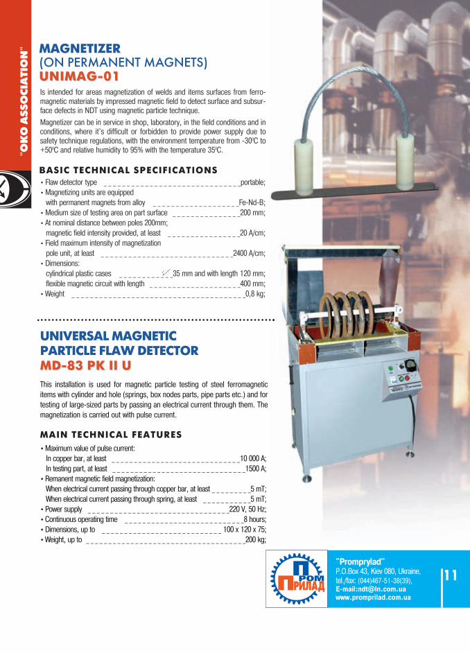
with permanent magnets from alloy _ _ _ _ _ _ _ _ _ _ _ _ _ _ _ _ _ _ _Fe-Nd-B;• Medium size of testing area on part surface _ _ _ _ _ _ _ _ _ _ _ _ _ _ _200 mm;• At nominal distance between poles 200mm;
magnetic field intensity provided, at least _ _ _ _ _ _ _ _ _ _ _ _ _ _ _ _20 A/cm;• Field maximum intensity of magnetization
pole unit, at least _ _ _ _ _ _ _ _ _ _ _ _ _ _ _ _ _ _ _ _ _ _ _ _ _ _ _ _ _2400 A/cm;• Dimensions:
cylindrical plastic cases _ _ _ _ _ _ _ _ _ _ _ _35 mm and with length 120 mm;flexible magnetic circuit with length _ _ _ _ _ _ _ _ _ _ _ _ _ _ _ _ _ _ _ _400 mm;
• Weight _ _ _ _ _ _ _ _ _ _ _ _ _ _ _ _ _ _ _ _ _ _ _ _ _ _ _ _ _ _ _ _ _ _ _ _ _ _0,8 kg;
MAGNETIZER(ON PERMANENT MAGNETS)UNIMAG-01UNIMAG-01Is intended for areas magnetization of welds and items surfaces from ferro-magnetic materials by impressed magnetic field to detect surface and subsur-face defects in NDT using magnetic particle technique.
Magnetizer can be in service in shop, laboratory, in the field conditions and inconditions, where it's difficult or forbidden to provide power supply due tosafety technique regulations, with the environment temperature from -300C to+500C and relative humidity to 95% with the temperature 350C.
MAIN TECHNICAL FEATURES
UNIVERSAL MAGNETIC PARTICLE FLAW DETECTOR MD-83 PK II UMD-83 PK II U
BASIC TECHNICAL SPECIFICATIONS
••Maximum value of pulse current:In copper bar, at least _ _ _ _ _ _ _ _ _ _ _ _ _ _ _ _ _ _ _ _ _ _ _ _ _ _ _ _ _10 000 A;In testing part, at least _ _ _ _ _ _ _ _ _ _ _ _ _ _ _ _ _ _ _ _ _ _ _ _ _ _ _ _ _ _1500 A;
••Remanent magnetic field magnetization:When electrical current passing through copper bar, at least _ _ _ _ _ _ _ _ _5 mT;When electrical current passing through spring, at least _ _ _ _ _ _ _ _ _ _ _5 mT;
••Power supply _ _ _ _ _ _ _ _ _ _ _ _ _ _ _ _ _ _ _ _ _ _ _ _ _ _ _ _ _ _ _ _220 V, 50 Hz;••Continuous operating time _ _ _ _ _ _ _ _ _ _ _ _ _ _ _ _ _ _ _ _ _ _ _ _ _ _ _8 hours;••Dimensions, up to _ _ _ _ _ _ _ _ _ _ _ _ _ _ _ _ _ _ _ _ _ _ _ _ _ _ _ 100 x 120 x 75;••Weight, up to _ _ _ _ _ _ _ _ _ _ _ _ _ _ _ _ _ _ _ _ _ _ _ _ _ _ _ _ _ _ _ _ _ _ _ _200 kg;
This installation is used for magnetic particle testing of steel ferromagneticitems with cylinder and hole (springs, box nodes parts, pipe parts etc.) and fortesting of large-sized parts by passing an electrical current through them. Themagnetization is carried out with pulse current.
"Promprylad"P.O.Box 43, Kiev 080, Ukraine,tel./fax: (044)467-51-38(39),E-mail:[email protected] www.promprilad.com.ua
11

Device is intended to detect surface cracks in cylindri-cal rolls with diameter 32 mm and length 52 mm, a part
of rolling bearings No2726 used in axel-boxes of pas-senger and freight cars.
•Minimum defect dimensions:
Crack length, at least _ _ _ _ _ _ _ _ _ _ _ _ _ _ _ _ _ _ _ _ _ _ _ _ _ _ _ _3 mm
Crack opening, at least _ _ _ _ _ _ _ _ _ _ _ _ _ _ _ _ _ _ _ _ _ _ _ _0,002 mm
Crack depth _ _ _ _ _ _ _ _ _ _ _ _ _ _ _ _ _ _ _ _ _ _ _ _ _ _ _ _ _ _ _ _0,1 mm
•Settling time of flaw detector operating mode, at least _ _ _ _ _ _ _ _10 min.
•Testing productivity, at least _ _ _ _ _ _ _ _ _ _ _ _ _ _ _ _ _ _ _ _ _ 120 roll/hour
•One cassette with 15 rollers testing time, up to _ _ _ _ _ _ _ _ _ _ _ _10 min.
•Storage of inspected rollers sets testing results, at least _ _ _ _ _ _250 x 15
•Communication with PC.
•Flaw detector mains power supply:
voltage _ _ _ _ _ _ _ _ _ _ _ _ _ _ _ _ _ _ _ _ _ _ _ _ _ _ _ _ _220 V +\-10%
frequency _ _ _ _ _ _ _ _ _ _ _ _ _ _ _ _ _ _ _ _ _ _ _ _ _ _ _ _50 Hz +\- 1%
•Power, up to _ _ _ _ _ _ _ _ _ _ _ _ _ _ _ _ _ _ _ _ _ _ _ _ _ _ _ _ _ _ _ _ _ _60 VA
•Non-stop operating time, at least _ _ _ _ _ _ _ _ _ _ _8 hours
•Dimensions _ _ _ _ _ _ _ _ _ _ _ _ _ _ _ _880 x 250 x 435 mm
•Weight, up to _ _ _ _ _ _ _ _ _ _ _ _ _ _ _ _ _ _ _ _ _ _ _21 kg.
•Operating temperature range _ _ _ _ _ _ _ _ _ _ _ _ _0…+350C
EDDY-CURRENTAUTOMATED FLAW
DETECTOR VD - 131ND "INSPECTOR"
TECHNICAL SPECIFICATIONS:
"OK
O A
SS
OC
IAT
ION
"
"Promprylad"P.O.Box 43, Kiev 080, Ukraine,
tel./fax: (044)467-51-38(39),E-mail:[email protected]
www.promprilad.com.ua
12

"OK
O A
SS
OC
IAT
ION
"
• channels pre setup;• possibility of operating setups creation on the basis ofpredefined setups;• embedded memory for test results registration for all thechannels;• the traveled distance and velocity registration duringcontinuous inspection;• large color high resolution display;• testing results display as symbolic circuit. A and B scans
display in real time;• visual and sound flaw alarm system;• possibility of manual UT of welds and switches;• data collect mode;• simultaneous use of different sounding schemes;• full functionality of a universal flaw detector;• functions of automated high-speed UT means;• possibility of channels number increasing.
“ULTRACON-SERVICE”P.O.Box 31, Kiev 111, Ukraine, tel./fax: +380 44 531-37-26(27); E-mail: [email protected]
17
Ultrasonic rail flaw detector UDS2-73 is intended for continues mechanized testing at a speed up to 4 km/h for defectsdetection in both rails along the running surface and rail cross-section, excepting rail foot wings, manual sampling test ofwelded joints and separate rails cross-sections, characterization of detected defects and for testing results storage in perma-nent memory.
General features:
BASIC TECHNICAL SPECIFICATIONS:•Number of channels, _ _ _ _ _ _ _ _ _ _ _ _ _ _ _ _ _ _ _ _ _ _ _ _ _ _ _ _ _ _ _ _ _ _ _ _ _ _ _ _ _ _ _ _ _ _ _ _ _ _ _ _ _ _ _total 28• for continues testing _ _ _ _ _ _ _ _ _ _ _ _ _ _ _ _ _ _ _ _ _ _ _ _ _ _ _ _ _ _ _ _ _ _ _ _ _ _ _ _ _ _ _ _ _ _ _ _ _ _ _ _ _ _ _ _ _ _22• for manual testing _ _ _ _ _ _ _ _ _ _ _ _ _ _ _ _ _ _ _ _ _ _ _ _ _ _ _ _ _ _ _ _ _ _ _ _ _ _ _ _ _ _ _ _ _ _ _ _ _ _ _ _ _ _ _ _ _ _ _ _2• rail head test techniques and zones:1. pulse echo technique with angle-beam probe for the testing of the central part, running and non-running rail head edgealong and against movement;2. echo images technique with angle-beam probe for the testing of the rail head central part along and against movement;3. echo images technique for the testing of running and non-running rail head edge along and against movement;• techniques and testing zones of the rail web and its projections onto base:1. pulse echo and echo images techniques using straight beam double crystal probe;2. pulse echo techniques with angle-beam probe along and against movement for base and bolt holes testing;•probes operating frequencies… _ _ _ _ _ _ _ _ _ _ _ _ _ _ _ _ _ _ _ _ _ _ _ _ _ _ _ _ _ _ _ _ _ _ _ _ _ _ _ _ _ _ _ _ _ _ _ _2,5 MHz•operating temperature range… _ _ _ _ _ _ _ _ _ _ _ _ _ _ _ _ _ _ _ _ _ _ _ _ _ _ _ _ _ _ _ _ _ _ _ _ _ _ _ _ _ _ _ _ _ _-30…+50 °C
PIEZOELECTRIC RESONATORSAND PROBES FOR MANUALTESTING FOR ULTRASONICRAIL FLAW DETECTORS
Probes (resonators) are intended for:• in service non-destructive testing of railway track quality by the railway services;• assemblage in probes blocks for demountable rail flaw detectors and mobile means of ultrasonic rail testing;• manual testing;
Different types of probes can be produced: • straight beam single crystal; • angle beam single crystal;• multi-element angle beam single crystal; • straight beam double crystal;
DISTINCTIVE FEATURE OF THESE TRANSDUCERS IS HIGH ENDURANCE OFTHEIR WORKING SURFACE.
Probe Probe angle Probe double Directivity Probe type for steel according conversion pattern frequency
to SO-3R coefficient, width0 dB 0 MHz
ПР-0 0 ± 3 - 41+14-2 15 ± 5 2,5 ± 0,25
ПР-РС-0* 0 ± 3 - 52+14-2 15 ± 5 2,5 ± 0,25
ПР-РС-0-01 0 ± 3 - 53+14-2 15 ± 5 2,5 ± 0,25
ПР-42 42 ± 2 - 44+14-2 7 ± 2 2,5 ± 0,25
ПР-45* 45+1-3 - 44+14
-2 7 ± 2 2,5 ± 0,25ПР-50* 50+1
-3 - 50+14-2 9 ± 3 2,5 ± 0,25
ПР-55* 55+3-1 - 50+14
-2 9 ± 3 2,5 ± 0,25ПР-58* 58 ± 2 - 53+14
-2 9 ± 2 2,5 ± 0,25ПР-65* 65+1
-3 - 53+14-2 12 ± 4 2,5 ± 0,25
ПР-70* 70+1-3 - 53+14
-2 12 ± 4 2,5 ± 0,25ПР-2x42 42 ± 2 - 48+14
-2 10± 2 2,5 ± 0,25ПР-2x45 45+1
-3 - 48+14-2 10 ± 2 2,5 ± 0,25
ПР-41/49 41 ± 2 - 48+14-2 12 ± 4 2,5 ± 0,25
49 ± 2 - 53+14-2 12 ± 4 2,5 ± 0,25
ПР-2x58-68 58 ± 2 - 53+14-2 10 ± 4 2,5 ± 0,25
ПР-2x58-112 58 ± 2 - 53+14-2 10 ± 4 2,5 ± 0,25
*these probes are also produced for manual testing Operating temperature range is from - 40 to +50 0C
BASIC TECHNICAL SPECIFICATIONS:
Rail Flaw Detector UDS2-73UDS2-73

ULTRASONICTHICKNESS
GAUGES TUZ-1TUZ-2
Is intended for thickness measurement of various items,including those that could be accessed only from one side.
Basic technical specifications:
• Measurement range (in steel) _ _ _ _ _ _ _ _ _ _ _ _0,6…300• Resolution of thickness measurement, mm _ _ _ _ _ _ _ _.0,
TUZ-1 TUZ-2• Differentional mode
(thickness deviation measurement) + —• Scanning + —• Lower thickness limit overrun alarm + —• Probe zero calibration manual automatic• Measurements results built in memory (2400 measurements) —• PC interface and reports generation + —• Time of continues operation powered from
fully charged batteries, at least, hours 25 20• Operating temperature range -10…+ 45 0С -30…+ 50 0С• Case protection level according to GOST 14254 IP53 IP65• Dimensions of electronic unit, mm 164 х 84 х 30 126 х 85 х 35• Weight of electronic unit, up to, kg 0,4 0,35
ADDITIONAL MEASUREMENT MODES
"OK
O A
SS
OC
IAT
ION
"
“ULTRACON-SERVICE”P.O.Box 31, Kiev 111, Ukraine,
tel./fax: +380 44 531-37-26(27); E-mail: [email protected]
www.ultracon-service.com.ua
18

“ULTRACON-SERVICE”P.O.Box 31, Kiev 111, Ukraine, tel./fax: +380 44 531-37-26(27); E-mail: [email protected]
19
"OK
O A
SS
OC
IAT
ION
"
· operating temperatures range is from 10 to +50°C; · M - small sized, "MM" - miniature; * on MD2-0-1 sample
Test range on Probe angle Probe Signal/noise Overall Designation sample SO-1, on sample Effective zero, ratio, not worse dimensions,
SO-2 frequency up to than up toGOST 14782-86,
mm mm MHz mm dB mmП121-1,25-40-М-003 5...50 40±2 1,25±0,13 12 16 40 х 23 х 30
П121-1,25-45-М-003 5...50 45±2 1,25±0,13 15 16 40 х 23 х 30П121-1,25-50-М-003 5...50 50±2 1,25±0,13 15 16 40 х 23 х 30П121-1,25-60-М-003 5...50 60±2 1,25±0,13 15 16 40 х 23 х 30
П121-1,8-40-М-003 5...50 40±2 1,8±0,18 10 16 40 х 23 х 30П121-1,8-45-М-003 5...50 45±2 1,8±0,18 12 16 40 х 23 х 30П121-1,8-50-М-003 5...50 50±2 1,8±0,18 12 16 40 х 23 х 30П121-1,8-60-М-003 5...50 60±2 1,8±0,18 14 16 40 х 23 х 30
П121-2,5-40-М-003 5...50 40±2 2,5±0,25 10 16 40 х 23 х 30П121-2,5-45-М-003 5...50 45±2 2,5±0,25 10 16 40 х 23 х 30П121-2,5-50-М-003 5...50 50±2 2,5±0,25 12 16 40 х 23 х 30П121-2,5-60-М-003 5...45 60±2 2,5±0,25 12 16 40 х 23 х 30П121-2,5-65-М-003 5...45 65±2 2,5±0,25 13 16 40 х 23 х 30П121-2,5-68-М-003 5...40 68±2 2,5±0,25 13 16 40 х 23 х 30П121-2,5-70-М-003 5...40 70±2 2,5±0,25 14 16 40 х 23 х 30
П121-5-40-М-003 5...30 40±2 5±0,5 6 16 25 х 20 х 20П121-5-45-М-003 5...30 45±2 5±0,5 6 16 25 х 20 х 20П121-5-50-М-003 5...30 50±2 5±0,5 7 16 25 х 20 х 20П121-5-60-М-003 5...20 60±2 5±0,5 8 16 25 х 20 х 20П121-5-65-М-003 5...20 65±2 5±0,5 8 16 25 х 20 х 20П121-5-68-М-003 5...15 68±2 5±0,5 8 16 25 х 20 х 20П121-5-70-М-003 5...15 70±2 5±0,5 8 16 25 х 20 х 20П121-5-73-М-003 5...15 73±2 5±0,5 9 16 25 х 20 х 20П121-5-50-ММ-003 5...25 50±2 5±0,5 6 16 20 х 12 х 17П121-5-65-ММ-003 5...20 65±2 5±0,5 6 16 20 х 12 х 17П121-5-70-ММ-003 5...15 70±2 5±0,5 7 16 20 х 12 х 17
П121-10-65-М-003 0,7...25* 65±2 10±1 5 16 20 х 12 х 17П121-10-70-М-003 0,7...20* 70±2 10±1 5 16 20 х 12 х 1
ULTRASONIC CONTACT ANGLED-BEAM SINGLE CRYSTAL SMALL-SIZED TRANSDUCERS
ULTRASONIC PROBES FOR FLAW DETECTORS UD4-76, UD3-71, UD2-70, AND UD2-12*
APPEARANCE
Designation Effective frequency, Overall dimensions, up toMHz mm
П121-1,25-90-М-003 1,25 ± 0,13 40 х 23 х 30П121-1,8-90-М-003 1,8 ± 0,18 40 х 23 х 30П121-2,5-90-М-003 2,5 ± 0,25 40 х 23 х 30П121-5-90-М-003 5 ± 0,5 25 х 20 х 20
CONTACT ANGLE BEAM SINGLE CRYSTAL SURFACE WAVE PROBES
ULTRASONIC CONTACT STRAIGHT BEAM DOUBLE CRYSTAL PROBES· operating temperatures range is from -10 to +50°C
* These probes can be delivered at extra cost by customer's request.**for UD2-12 flaw detector the final three figures of probe - 002 designation (for example: P121-1,25-40-M-002)-operating temperatures range is from -10 to +50°C
Designation Reflector Test range on Probe Signal/Noise ratio at depths of Working surface diameter, MD4 samples, frequency, testing range, not worse than dimensions
mm mm MHz dB mmП112-2,5-12-003 1,6 2 - 30 2,5 ±0,25 16 ̆16П112-5-12-003 1,2 1 - 30 5 ± 0,5 16 ̆16П112-5-6-003 1,2 1 - 25 5 ± 0,5 16 ̆9П112-5-3х4-003 1,2 1 - 25 5 ± 0,5 16 13 х 18П112-2,5-10х4-003* 1,6 2 - 30 2,5 ± 0,25 16 15 х 13П112-2,5-4х10-003* 1,6 2 - 30 2,5 ± 0,25 16 25 х 9П112-2,5-4х15-003* 1,6 2 - 30 2,5 ± 0,25 16 35 х 9П112-1,25-20х6-003* 3,2 10 - 90 1,25 ± 0,13 16 ̆32П112-2,5-20х6-003* 1,6 10 - 70 2,5 ± 0,25 16 ̆32П112-5-20х6-003* 1,2 10 - 70 5 ±0,5 16 ̆32
Appearance
Appearance

SPECIAL CONTACT DOUBLE CRYSTAL CREEPING WAVE PROBESTest range Probe angle Effective Probe Overall
Designation on sample on sample frequency, zero, dimensions,SO-1 SO-2, up to up to
mm MHz mm*П122-2,5-65-ГВ-003 5-50 65 ± 2 2,5 ± 0,25 14 35 х 23 х 28
ULTRASONIC CONTACT STRAIGHT BEAM DOUBLE CRYSTAL PROBES FOR THICKNESS GAUGING OF TURBINE BLADES
* These probes can be delivered at extra cost.-operating temperatures range is from -10 to +50°C
ULTRASONIC CONTACT ANGLE BEAM DOUBLE CRYSTAL PROBES FOR UT OF SMALL DIAMETERS PIPES WITH THIN WALLS
* These probes can be delivered at extra cost
Wedge Pipes Testing Effective S/N Overall Designation angle, diameters range frequency, ratio, dimensions,
(хх)0 mm mm MHz dB mm
П122-5-51-dхх-003* 51 25; 28; 30; 32; 36; 38; 42; 45; 2…5 10 ± 1 16 25 х 20 х 20 П122-5-53-dхх-003* 53 48; 50; 57; 60; 76; 83; 89; 2…5 10 ± 1 16 25 х 20 х 20 П122-5-55-dхх-003* 55 102; 108; 114;133; 159; 219 2…5 10 ± 1 16 25 х 20 х 20
Wedge Testing Effective Pipes S/N Overall Designation angle, range frequency, diameters ratio, dimensions,
(хх)0 mm MHz mm dB mm
П121-5-40-dхх-003 40 9…14 5 ± 0,5 25; 28; 30; 32; 36; 38; 16 25 х 20 х 20
П121-5-51-dхх-003 51 9…12 5 ± 0,5 42; 45; 48; 50;57; 60; 16 25 х 20 х 20П121-5-53-dхх-003 53 6…9 5 ± 0,5 76; 83; 89;102; 108; 114; 16 25 х 20 х 20П121-5-55-dхх-003 55 3,5…6 5 ± 0,5 133; 159; 219 16 25 х 20 х 20П121-5-58-dхх-003* 58 4…6,5 5 ± 0,5 16 25 х 20 х 20
ULTRASONIC CONTACT ANGLE BEAM SINGLE CRYSTAL PROBES FOR UT OF SMALL DIAMETERS AND PIPES
*is intended for welds from austenitic steel
Thicknesses MinimumDesignation Probe measurement curvature Overall
frequency range, radius dimensions,40 x 13
MHz mm mm mm mmП112-10-2х3-003* 10±1 0,5-4,0 2,0 10,0 2 х 6
* These probes can be delivered at extra cost by customer's request.- PROBES WITH THE REQUIRED PROBE FREQUENCY, CRYSTAL DIAMETER AND WEDGE ANGLE CAN BE PRODUCED.- operating temperatures range is from -10 to +50°C
Probe Thicknesses Working OverallDesignation frequency measurement range, surface dimensions,
40 x 13 dimensions,MHz mm mm mm
П112-10-6/2-Т-003* 10 ± 1 0,6 - 20 ˘ 9 ˘ 22 х 39П112-5-10/2-Т-003* 5 ± 0,5 1-100 ˘ 14 ˘ 22 х 42П112-2.5-12/2-Т-003* 2,5 ± 0,25 3-300 ˘ 16 ˘ 24 х 42
ULTRASONIC CONTACT STRAIGHT BEAM DOUBLE CRYSTAL PROBES FOR THICKNESS GAUGING
* These probes can be delivered at extra cost by customer's request.- operating temperatures range is from -10 to +50°C**- for UD2-12 flaw detector the final three figures of probe -002 designation (for example: P121-1,25-40-M-002).
Appearance
Appearance
Appearance
Appearance
Appearance
Salient, Concave,
"OK
O A
SS
OC
IAT
ION
"
“ULTRACON-SERVICE”P.O.Box 31, Kiev 111, Ukraine,
tel./fax: +380 44 531-37-26(27); E-mail: [email protected]
www.ultracon-service.com.ua
20

SPECIAL ULTRASONIC CONTACT ASSEMBLED PROBES FOR PIPES BENDINGS TESTING
•operating temperatures range is from -10 to +50°C**-for UD2-12 flaw detector the final three figures of probe -002 designation (for example: P121-1,25-40-M-002).
Testing range Conversion Signal / Noise ratio WorkingDesignation Reflector on the samples maximum in the testing range, surface
diameter, MD4, MD18 frequency not worse than dimensions
mm mm MHz dB mmП111-1,25-К20-003 3,2 15-180 1,25±0,13 16 ̆22
П111-2,5-К12-003 1,6 10-180 2,5±0,25 16 ̆14П111-2,5-К20-003 1,6 25-400 2,5±0,25 16 ̆22П111-5-К6-003 1,2 5-70 5±0,5 16 ̆8П111-5-К12-003 1,2 15-200 5±0,5 16 ̆14П111-10-К4-003 1,0 5-30 10±1 16 ̆6
ULTRASONIC CONTACT STRAIGHT BEAM DOUBLE CRYSTAL PROBES
SPECIAL ULTRASONIC CONTACT ANGLE BEAM ASSEMBLED PROBES
DEMOUNTABLE PROBE PROBE
Test range Probe angle Probe Effective Diameter Designation on sample on sample designation frequency, of piezoelectric
SO-1 SО-2 cell,mm 0 MHz mm
П121-2,5-40-Р-003* 5-50 40 ±2 П111-2,5-П12-Р-003 2,5 ± 0,25 12П121-2,5-45-Р-003* 5-50 45 ±2 П111-2,5-П12-Р-003 2,5 ± 0,25 12П121-2,5-50-Р-003* 5-50 50 ±2 П111-2,5-П12-Р-003 2,5 ± 0,25 12П121-2,5-60-Р-003* 5-45 60 ±2 П111-2,5-П12-Р-003 2,5 ± 0,25 12П121-2,5-65-Р-003* 5-45 65 ±2 П111-2,5-П12-Р-003 2,5 ± 0,25 12П121-2,5-70-Р-003* 5-40 70 ±2 П111-2,5-П12-Р-003 2,5 ± 0,25 12
ASSEMBLED PROBE WEDGEPROBE
Resonator Effective Diameter of Wedge Working surfaceDesignation Designation frequency, piezoelectric angle diameter
cell ( XX ) ( YY )MHz mm 0 mm
*П121-2,5-хх-dyy-Р-003* П111-2,5-П12-Р-003 2,5±0,25 12 30, 40 57, 60, 76, 89,108, 114, *П121-5-хх-dyy-Р-003* П111-5-П8-Р-003 5±0,5 8 133, 159, 219, 273, 325, 426
* These probes can be delivered at extra cost by customer's request. - operating temperatures range is from -10 to +500C
Reflector Testing Conversion Signal / Noise ratio WorkingDesignation diameter, range maximum in the testing range, surface
frequency not worse than dimensionsmm mm MHz dB mm
П111-1,25-20П-003* 4,0 30-180 1,25 ± 0,13 10 ˘ 23П111-2,5-12П-003* 1,6 20-180 2,5 ± 0,25 10 ˘ 16П111-2,5-20П -003* 1,6 30-400 2,5 ± 0,25 10 ˘ 23П111-5-6П -003* 1,2 15-70 5 ± 0,5 10 ˘ 16П111-5-12П -003* 1,2 15-130 5 ± 0,5 10 ˘ 16
* These probes can be delivered at extra cost by customer's request. - operating temperatures range is from -10 to +500C
ULTRASONIC CONTACT STRAIGHT BEAM SINGLE CRYSTAL WITH ELASTIC PROTECTOR FOR WORK ON ROUGH SURFACES
* These probes can be delivered at extra cost by customer's request - operating temperatures range is from -10 to +500C
* These probes can be delivered at extra cost by customer's request - operating temperatures range is from -10 to +50°C
Reflector Testing range Conversion Signal / Noise ratio WorkingDesignation diameter, on the samples maximum in the testing range, surface
MD4, MD18 frequency not worse than dimensionsmm mm MHz dB mm
П112-1,25-20x6-П-003* 3,2 90-180 1,25 ± 0,13 16 ˘ 32П112-2,5-20x6-П-003* 1,6 30-90 2,5 ± 0,25 16 ˘ 32П112-5-20x6-П-003* 1,2 10-70 5 ± 0,5 16 ˘ 32
ULTRASONIC CONTACT STRAIGHT BEAM DOUBLE CRYSTAL PROBES WITH ELASTIC PROTECTOR FOR WORK ON ROUGH SURFACES
Appearance
Appearance
Appearance
Appearance
Appearance
“ULTRACON-SERVICE”P.O.Box 31, Kiev 111, Ukraine, tel./fax: +380 44 531-37-26(27); E-mail: [email protected]
21
"OK
O A
SS
OC
IAT
ION
"

ULTRASONIC
CALIBRATIONCALIBRATIONBLOCKSBLOCKS
• Set of calibration blocks KOU2-M
according to GOST 14782-86 for
measurement of main parameters
of ultrasonic welds testing.
• Ultrasonic calibration blocks V1 and V2
according to ISO 7963, B.S. 2704, DSTU
4002-2000
• Calibration blocks from the MD4-0 and
MD2-0 sets with the "flat-bottom hole"
reflectors according to GOST 23667-85
• Calibration blocks SО-1R and SО-3R
from the KGSO-R set according to GOST
18576-85 for the rail flaw detectors
setup.
• Enterprise calibration blocks (SOP) with
the notch type reflectors for ultrasonic
flaw detectors parameters setup when
testing the welds according
to SOU-NMPE 40.1.17.302:2005,
VSN 012-88, RD 22-205 and №23 SD-80
etc.
"OK
O A
SS
OC
IAT
ION
"
“ULTRACON-SERVICE”P.O.Box 31, Kiev 111, Ukraine, tel./fax: +380 44 531-37-26(27); E-mail: [email protected]
23

Ukrainian scientific research institute for non-destructive testing
P.O.Box 43, Kiev 04080, Ukrainetеl./fax: (044) 531-37-26 (27)
Е-mail:[email protected]
24
SYSTEM OF AUTOMATED ACCEPTANCE NDT
OF RAILWAY WHEELSOF RAILWAY WHEELS
PURPOSESystem is intended for automated testing of solid
railway wheels in accordance with RD 32.144-2000.
•Testing productivity _ _ _ _ _ _ _ _60 wheels/hour•Ultrasonic channels quantity _ _ _ _ _ _ _ _ _ _ _21•Probes frequencies _ _ _ _ _ _ _ _ _2,5 and 5 MHz•Testing schemes:
- D1 wheel rim testing with longitudinal waves inradial direction from rolling surface;- D2 wheel rim testing with longitudinal waves inaxial direction from rim internal lateral surface;- H wheel hub testing with longitudinal waves from internal lateral surface;- D2b metal structure testing by echo imagestechnique;- W wheel disk testing with longitudinal waves indirection normal to surface.
•Express calibration;•Operative short-form of testing results imaging;•Paper report printing for each inspected or each
rejected wheel by operator's request;•Complete testing results storage for each
inspected wheel in electronic form;•Possibility of their review, analysis and printing;•Reports creation;•Testing results can be archived on DVD.
Functionality and technical specifications
"OK
O A
SS
OC
IAT
ION
"

100% complex ultrasonic and eddy current testing;• Testing time (not accounting for axle transfer time), up to - 6 min.• Paper report printing for every inspected or every rejected
axle by operator's request;• Operative short-form of testing results imaging;• Complete testing results storage for every inspected axle in electronic
form, with the possibility of further review, analysis and printing;• Statistical reports creation;• Testing results can be archived on DVDs.
Ukrainian scientific research institute for non-destructive testingP.O.Box 43, Kiev 04080, Ukrainetеl./fax: (044) 531-37-26 (27)Е-mail:[email protected]
25
FUNCTIONALITY AND TECHNICAL SPECIFICATIONS
SYSTEM SYSTEM OF AUTOMATED ACCEPTANCE NDT OF AUTOMATED ACCEPTANCE NDT OF RAIL AXELS
EDDY CURRENT OPTION:• Number of eddy-current channels _ _ _ _ _ _ _ _28—32;• Eddy current probes type _ _ _ _ _ _ _multi-differential;• Eddy current probes
operating frequencies _ _ _ _ _ _ _ _ _ _ _100-300 kHz;• Design of eddy current probes
permits to detect flaws such as cracks, folds with following geometry:Relative extent _ _ _ _ _ _ _ _ _ _ _ _ _ _ _at least 4 mm,Depth _ _ _ _ _ _ _ _ _ _ _ _ _ _ _ _ _ _ _at least 0.2 mm,Opening _ _ _ _ _ _ _ _ _ _ _ _ _ _ _ _ _ _at least 10 µm(it meets the requirements of magnetic particles testing for B class)
ULTRASONIC OPTION• Ultrasonic channels quantity _ _ _ _ _ _ _ _ _ _ _ _ _ _ _ _ _ _ _ _ _ _ _16;• Operating probe frequency _ _ _ _ _ _ _ _ _ _ _ _ _ _ _ _ _ _2.5, 5 MHz;• Testing schemes:
- A1 and T1 testing from end surfaces for flaw detection and metalstructure testing;- A2 and T2 testing from cylindrical surfaces for flaw detection andmetal structure uniformity testing ;- A3 testing by angle-beam probe for flaw detection in areas underhollow chamfers;
"OK
O A
SS
OC
IAT
ION
"

• Complex ultrasonic and eddy current testing of body and end sections of welded and seamless pipes of major and medium diameters;
• 100% testing process and results registration;• end sections testing time
of flawless pipe is _ _ _ _ _ _ _ _ _ _ _ _ _ _up to 2 min.;pipe body testing rate (for pipe with diameter 1422 mm)is, at least _ _ _ _25 running meters of pipes per hour;
• test fact marking and marking of defective regions coordinates;
• sound and light automatic flaw alarm system;• possibility of video observation system integration
for distant testing process control;• data transmission via Ethernet channel;• possibility of axial weld ultrasonic testing;
Ukrainian scientific research institute for non-destructive testing
P.O.Box 43, Kiev 04080, Ukrainetеl./fax: (044) 531-37-26 (27)
Е-mail:[email protected]
26
SYSTEM SYSTEM OF AUTOMATED NDT OF PIPES ENDSOF AUTOMATED NDT OF PIPES ENDSON THE BASIS OF MULTI-CHANNEL FLAW DETECTOR"UNISCAN LUCH" "UNISKAN LUCH КТ-7"
FUNCTIONALITY AND TECHNICAL SPECIFICATIONSUltrasonic option• flaws types - flat flaws such as delaminations
and longitudinal cracks;• number
of ultrasonic channels _ _ _ _up to 48 (36 by default);• ultrasonic probes
operating frequencies _ _ _ _ _ _ _ _ _ _ _ _ _1-10 MHz;• individual acoustic coupling control of each probe;• testing results presentation both in the form
of overall diagram in real time and B-scans image in different projections for post factum review.
Eddy current option• flaws types - surface flaws such as cracks,
fold, void etc.• number of eddy
current channels _ _ _ _ _ _ _up to 128 (24 by default);• eddy-current probes type — multi-differential;• testing results presentation in the form of overall diagram
in real time, single channel signals presentations on complex plane;
"OK
O A
SS
OC
IAT
ION
"

"OK
O A
SS
OC
IAT
ION
"
•Maximum channels quantity in system: _ _ _ _ _ _ _ _ _ _ _ _ _ _ _ _ _ _ _ _ _ _ _up to 100.•Maximum distance from synchronizer to channel _ _ _ _ _ _ _ _ _ _ _ _ _ _ _ _ _ _100 m.•Maximum distance from synchronizer to PC _ _ _ _ _ _ _ _ _ _ _ _ _ _ _ _ _ _ _ _ _100 m.•Maximum distance between synchronizers _ _ _ _ _ _ _ _ _ _ _ _ _ _ _ _ _ _ _ _ _ _100 m.•System performance:
AE signals registration with one channel: _ _ _ _ _ _ _ _ _ _ _ _ _ _ _ _ _up to 1000 sig/s;AE signals registration with the whole system: _ _ _ _ _ _ _ _ _ _ _ _ _ _up to 15700 sig/s
•Gain range _ _ _ _ _ _ _ _ _ _ _ _ _ _ _ _ _ _ _ _ _ _ _ _ _ _ _ _ _ _ _ _ _ _ _ _ _ _ _ _15-68 dB.•Noise level recalculated to the channel input, _ _ _ _ _ _ _ _ _ _ _ _ _ _ _ _ _ _up to 5 mV•Operating frequency range of AE signals reception _ _ _ _ _ _ _ _ _ _ _ _ _ _ _20-800 kHz •Amplitude-frequency characteristic irregularity in pass band _ _ _ _ _ _ _ _ _ _ _ _1,5 dB•ADC _ _ _ _ _ _ _ _ _ _ _ _ _ _ _ _ _ _ _ _ _ _ _ _ _ _ _ _ _ _ _ _ _ _ _ _ _ _ _ _2,5 MHz, 16 bit•Range of noise cutoff level (threshold level) change _ _ _ _ _ _ _ _ _ _from -32 to 123 dB•Range of adjustable and measurable time parameters _ _ _ _ _ _ _ _ _ _ _ _1 ms - 65 ms •Measurement error of AE signal amplitude _ _ _ _ _ _ _ _ _ _ _ _ _ _ _ _ _ _ _ _ _ _ _±1 dB•Measurement error of AE signals arrival time difference _ _ _ _ _ _ _ _ _ _ _ _ _ _±0,5 ms•Conversion frequency of ADC in parametric channels _ _ _ _ _ _ _ _ _ _ _ _ _ _ _ _ _50 Hz•Amplitude measurement error in parametric channels _ _ _ _ _ _ _ _ _ _ _ _ _ _ _ _±2,5%•AE module operation conditions:
Protection level of AE module (channel) case from water and solid bodies penetration according to GOST 14254 _ _ _ _IP65
•Environment temperature range _ _ _ _ _ _ _ _ _ from -200C to +500C.•Relative humidity at temperature 250 _ _ _ _ _ _ _ _ _ _ _ _ _up to 95%.•Atmospheric pressure _ _ _ _ _ _ _ _at least 460 mm mercury column.
• Arbitrary (within maximum) quantity of AE channels and parametric channels.• Possibility of system growing through additional channels gaining.• Time graphs and diagrams construction (in real time and post-processing).• Time graphs and diagrams construction of interrelation of AE signals
and events parameters (in real time and post-processing).• AE events and sources location (in real time and post-processing).• Built-in digital oscilloscope in each AE channel.• Built-in software-controlled AE signals simulator in each channel.• Procedures of speed measurement and channels
auto-location on test object.
Is intended for NDT and technical state evaluation of critical objects. The aim of AE testing is coordinates definition and monitoring of AE signal sources(flaws) of objects being tested - pressure vessels, oil storages, pipelines, bridges,cast parts of railway car trucks and others engineering and technological structuresand parts.
GALS-1GALS-1AE TESTING SYSTEM
SYSTEM FEATURES
BASIC TECHNICAL SPECIFICATIONS
PURPOSE
Ukrainian scientific research institute for non-destructive testingP.O.Box 43, Kiev 04080, Ukrainetеl./fax: (044) 531-37-26 (27)Е-mail:[email protected]
27

"OK
O A
SS
OC
IAT
ION
"
Ukrainian scientific research institute for non-destructive testing
P.O.Box 43, Kiev 04080, Ukrainetеl./fax: (044) 531-37-26 (27)
Е-mail:[email protected]
SYSTEM OF SOUND VELOCITY MEASUREMENTUISU-01UISU-01
Is intended for measurementof longitudinal waves
velocity in samples with plane-parallel
edges.
•Measurable velocity range _ _ _ _ _ _ _ _ _ _ _ _ _ _ _ _ _ _ _ _ _ _ _ _ _ _ _ _ _ _ _ _ _ _ _ _ _ _ _ _from 1700 to 7000 m/s•Nominal frequencies _ _ _ _ _ _ _ _ _ _ _ _ _ _ _ _ _ _ _ _ _ _ _ _ _ _ _ _ _ _ _ _ _ _ _ _ _ _ _ _ _ _ _ _1,25; 2,5; 5; 10 MHz•Diffraction correction taking into account•Limit of main permissible relative measurement error of
longitudinal wave velocity _ _ _ _ _ _ _ _ _ _ _ _ _ _ _ _ _ _ _ _ _ _ _ _ _ _ _ _ _ _ _ _ _ _ _ _ _ _ _ _ _ _ _ _ _ _ _up to 0,2 %• Initial pulse amplitude _ _ _ _ _ _ _ _ _ _ _ _ _ _ _ _ _ _ _ _ _ _ _ _ _ _ _ _ _ _ _ _ _ _ _ _(with resolution 50 V)…50 - 300 V•Gain range _ _ _ _ _ _ _ _ _ _ _ _ _ _ _ _ _ _ _ _ _ _ _ _ _ _ _ _ _ _ _ _ _ _ _ _ _ _ _ _ _ _ _ _ _ _ _ _(with step 1 dB) 100 dB
Basic technical specifications:
28

"OK
O A
SS
OC
IAT
ION
"
Ukrainian scientific research institute for non-destructive testingP.O.Box 43, Kiev 04080, Ukrainetеl./fax: (044) 531-37-26 (27)Е-mail:[email protected]
29
UNIVERSAL MULTI-CHANNEL MULTI-FREQUENCY SYSTEMOF EDDY-CURRENT TESTING
•Channels quantity (according to consumer order) _ _ _ _ _ _ _ _ _ _from 4 to 32•Generator output voltage (with 6 dB decrease step) _ _ _ _ _ _ _ _ _ _ _ _ _ _ _8V•Maximum generator output current _ _ _ _ _ _ _ _ _ _ _ _ _ _ _ _ _ _ _ _ _100 mA•Frequency range _ _ _ _ _ _ _ _ _ _ _ _ _ _ _ _ _ _ _ _ _ _ _ _ _ _ _100 Hz… 1MHz•Gain factor for differential probe _ _ _ _ _ _ _ _ _ _ _ _ _ _ _ _ _ _ _ _ _20 - 86 dB•Gain factor of absolute probe _ _ _ _ _ _ _ _ _ _ _ _ _ _ _ _ _ _ _ _ _ _ _ _0 - 80 dB•ADC _ _ _ _ _ _ _ _ _ _ _ _ _ _ _ _ _ _ _ _ _ _ _ _ _ _ _ _ _ _ _ _ _ _ _ _ _ _ _ _12 bits
Is intended for highly-productive eddy-current testing of products and equipment
•100% results testing storage with possibility of their viewing after testing.
•Self-diagnostics system.•Peripheral devices control (mechanical motion
transducers, scanning devices etc.)•Production of scanners according
to the testing task.
Basic technical specifications:

"OKO"ASSOCIATION