laser series c15 alarms
DESCRIPTION
Alarms lists for Amada CNC laser machineTRANSCRIPT
LASER-AMNC-F ALARM-E03-200901
CNC LASER MACHINE (AMNC-F)
ALARM LISTS
2
CONTENTS
1. Description ........................................................................3 2. Machine alarms.................................................................4 3. Executor alarms ...............................................................32 4. Alarm details.....................................................................39
4-1. Details of machine alarm No. 2507 (INTERLOCK–Z) and No. 2527 (SENSING ALARM), and NC alarm (OVERTRAVEL–Z) ...........................39
4-1-1. Cutting near material edge and near already cut edge .................................39 4-1-2. Cutting from material edge (narrow strips, etc.) .40 4-1-3. Cutting or passing over already cut portion........40 4-1-4. Clearance in cutting end position .......................41 4-1-5. Step around cutting area ....................................41 4-1-6. Occurrence of plasma during cutting..................42 4-1-7. Cutting inclined surface ......................................42 4-1-8. Cutting bowed or vibrating material ....................42
Printed in Japan
Alarm Lists: CNC Laser Machine (AMNC-F) © 2009 by AMADA CO., LTD. No part of this publication may be photocopied or otherwise reproduced with-out the prior written permission of AMADA CO., LTD.
Jan. 2009
3
1. DESCRIPTION This machine has the following two types of alarms and displays them by different methods. These alarms are described on the pages that follow. Machine alarms: Alarms and warnings caused by the operation of the component parts and safety devices of the machine Executor alarms: Alarms related to regular-shaped hole macro commands The machine alarms come in two types: alarms that stop the operation of the machine and warnings that do not stop the operation of the machine.
NOTE
For the alarm numbers that appear on the MESSAGE display but not described in this manual, refer to the following manuals attached to the machine:
Alarm numbers 4xxx: Maintenance manual of Fanuc Laser C Series Other alarm numbers: Maintenance manual of Fanuc Series 160i-Model B
Some optional units have their own alarms. For these alarms, refer to the operation manuals of such optional units.
4
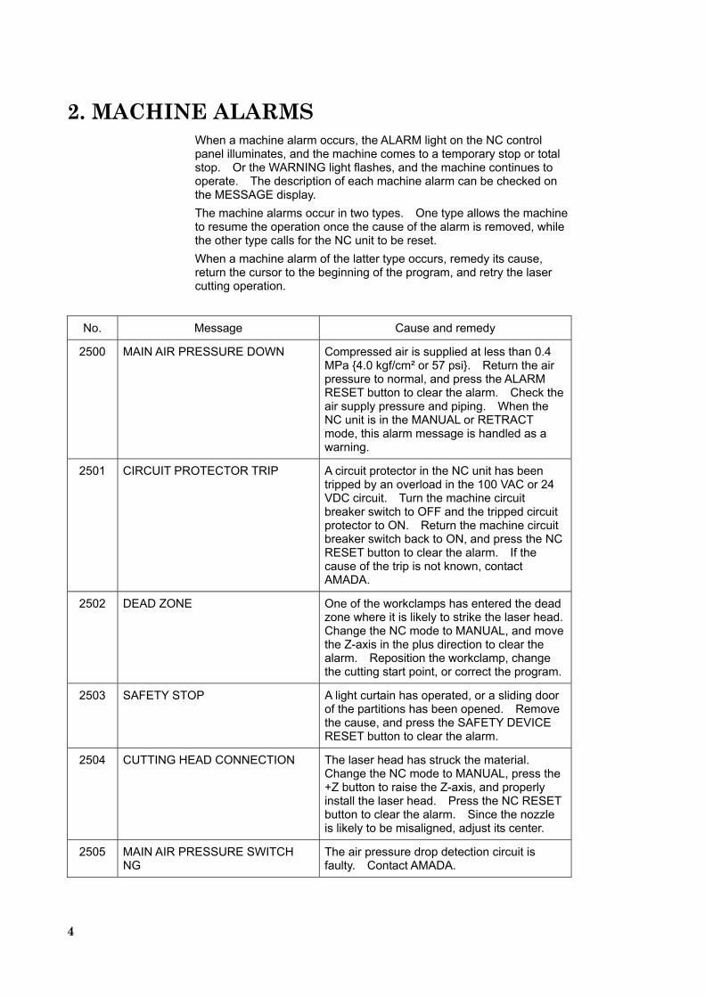
2. MACHINE ALARMS When a machine alarm occurs, the ALARM light on the NC control panel illuminates, and the machine comes to a temporary stop or total stop. Or the WARNING light flashes, and the machine continues to operate. The description of each machine alarm can be checked on the MESSAGE display. The machine alarms occur in two types. One type allows the machine to resume the operation once the cause of the alarm is removed, while the other type calls for the NC unit to be reset. When a machine alarm of the latter type occurs, remedy its cause, return the cursor to the beginning of the program, and retry the laser cutting operation.
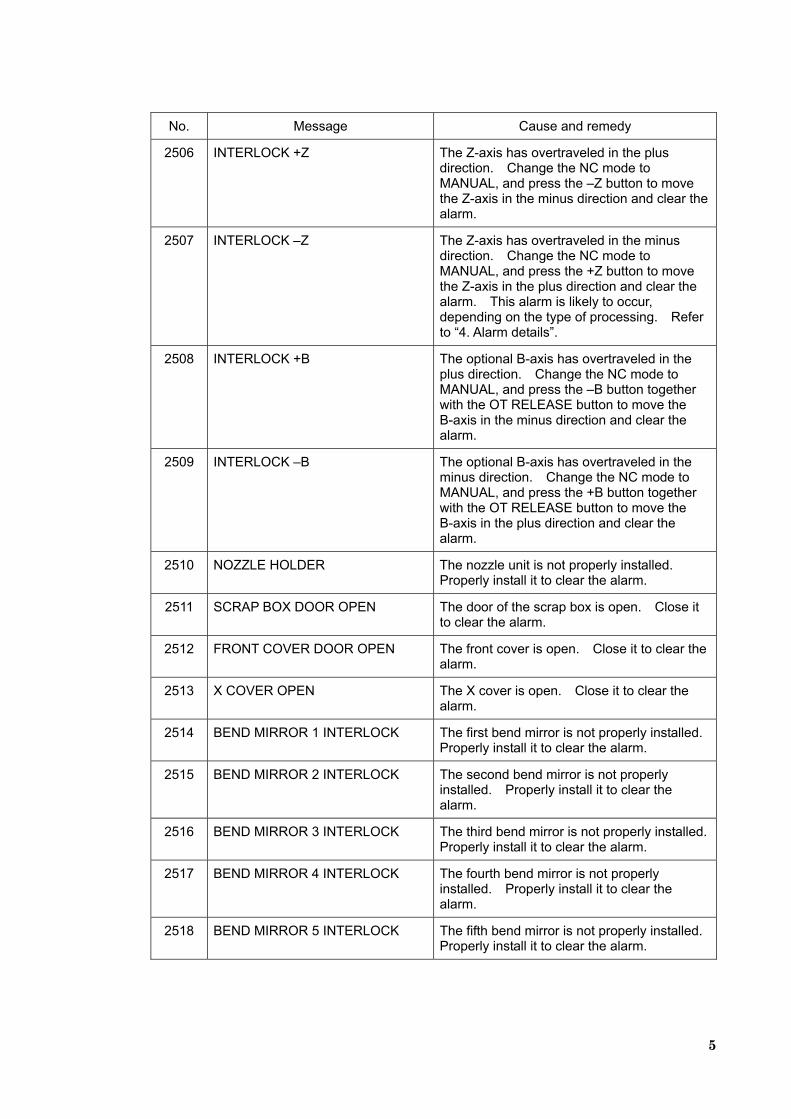
No. Message Cause and remedy
2500 MAIN AIR PRESSURE DOWN Compressed air is supplied at less than 0.4 MPa {4.0 kgf/cm² or 57 psi}. Return the air pressure to normal, and press the ALARM RESET button to clear the alarm. Check the air supply pressure and piping. When the NC unit is in the MANUAL or RETRACT mode, this alarm message is handled as a warning.
2501 CIRCUIT PROTECTOR TRIP A circuit protector in the NC unit has been tripped by an overload in the 100 VAC or 24 VDC circuit. Turn the machine circuit breaker switch to OFF and the tripped circuit protector to ON. Return the machine circuit breaker switch back to ON, and press the NC RESET button to clear the alarm. If the cause of the trip is not known, contact AMADA.
2502 DEAD ZONE One of the workclamps has entered the dead zone where it is likely to strike the laser head. Change the NC mode to MANUAL, and move the Z-axis in the plus direction to clear the alarm. Reposition the workclamp, change the cutting start point, or correct the program.
2503 SAFETY STOP A light curtain has operated, or a sliding door of the partitions has been opened. Remove the cause, and press the SAFETY DEVICE RESET button to clear the alarm.
2504 CUTTING HEAD CONNECTION The laser head has struck the material. Change the NC mode to MANUAL, press the +Z button to raise the Z-axis, and properly install the laser head. Press the NC RESET button to clear the alarm. Since the nozzle is likely to be misaligned, adjust its center.
2505 MAIN AIR PRESSURE SWITCH NG
The air pressure drop detection circuit is faulty. Contact AMADA.
5
No. Message Cause and remedy
2506 INTERLOCK +Z The Z-axis has overtraveled in the plus direction. Change the NC mode to MANUAL, and press the –Z button to move the Z-axis in the minus direction and clear the alarm.
2507 INTERLOCK –Z The Z-axis has overtraveled in the minus direction. Change the NC mode to MANUAL, and press the +Z button to move the Z-axis in the plus direction and clear the alarm. This alarm is likely to occur, depending on the type of processing. Refer to “4. Alarm details”.
2508 INTERLOCK +B The optional B-axis has overtraveled in the plus direction. Change the NC mode to MANUAL, and press the –B button together with the OT RELEASE button to move the B-axis in the minus direction and clear the alarm.
2509 INTERLOCK –B The optional B-axis has overtraveled in the minus direction. Change the NC mode to MANUAL, and press the +B button together with the OT RELEASE button to move the B-axis in the plus direction and clear the alarm.
2510 NOZZLE HOLDER The nozzle unit is not properly installed. Properly install it to clear the alarm.
2511 SCRAP BOX DOOR OPEN The door of the scrap box is open. Close it to clear the alarm.
2512 FRONT COVER DOOR OPEN The front cover is open. Close it to clear the alarm.
2513 X COVER OPEN The X cover is open. Close it to clear the alarm.
2514 BEND MIRROR 1 INTERLOCK The first bend mirror is not properly installed. Properly install it to clear the alarm.
2515 BEND MIRROR 2 INTERLOCK The second bend mirror is not properly installed. Properly install it to clear the alarm.
2516 BEND MIRROR 3 INTERLOCK The third bend mirror is not properly installed. Properly install it to clear the alarm.
2517 BEND MIRROR 4 INTERLOCK The fourth bend mirror is not properly installed. Properly install it to clear the alarm.
2518 BEND MIRROR 5 INTERLOCK The fifth bend mirror is not properly installed. Properly install it to clear the alarm.
6
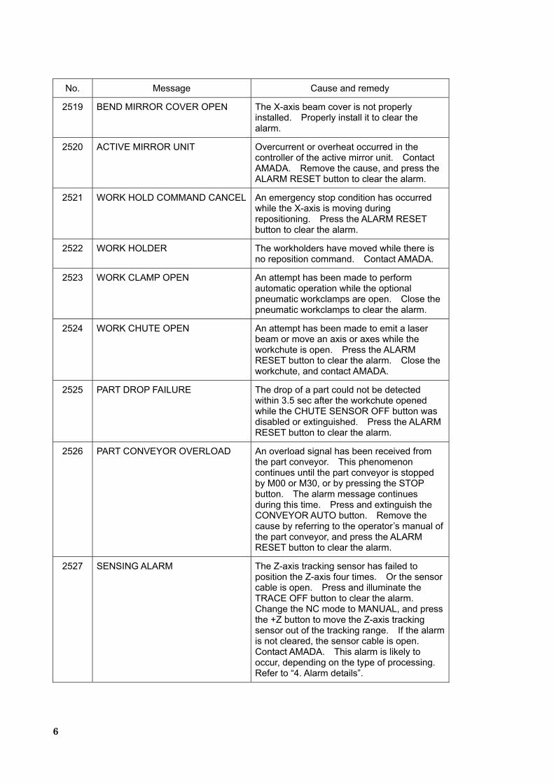
No. Message Cause and remedy
2519 BEND MIRROR COVER OPEN The X-axis beam cover is not properly installed. Properly install it to clear the alarm.
2520 ACTIVE MIRROR UNIT Overcurrent or overheat occurred in the controller of the active mirror unit. Contact AMADA. Remove the cause, and press the ALARM RESET button to clear the alarm.
2521 WORK HOLD COMMAND CANCEL An emergency stop condition has occurred while the X-axis is moving during repositioning. Press the ALARM RESET button to clear the alarm.
2522 WORK HOLDER The workholders have moved while there is no reposition command. Contact AMADA.
2523 WORK CLAMP OPEN An attempt has been made to perform automatic operation while the optional pneumatic workclamps are open. Close the pneumatic workclamps to clear the alarm.
2524 WORK CHUTE OPEN An attempt has been made to emit a laser beam or move an axis or axes while the workchute is open. Press the ALARM RESET button to clear the alarm. Close the workchute, and contact AMADA.
2525 PART DROP FAILURE The drop of a part could not be detected within 3.5 sec after the workchute opened while the CHUTE SENSOR OFF button was disabled or extinguished. Press the ALARM RESET button to clear the alarm.
2526 PART CONVEYOR OVERLOAD An overload signal has been received from the part conveyor. This phenomenon continues until the part conveyor is stopped by M00 or M30, or by pressing the STOP button. The alarm message continues during this time. Press and extinguish the CONVEYOR AUTO button. Remove the cause by referring to the operator’s manual of the part conveyor, and press the ALARM RESET button to clear the alarm.
2527 SENSING ALARM The Z-axis tracking sensor has failed to position the Z-axis four times. Or the sensor cable is open. Press and illuminate the TRACE OFF button to clear the alarm. Change the NC mode to MANUAL, and press the +Z button to move the Z-axis tracking sensor out of the tracking range. If the alarm is not cleared, the sensor cable is open. Contact AMADA. This alarm is likely to occur, depending on the type of processing. Refer to “4. Alarm details”.
7
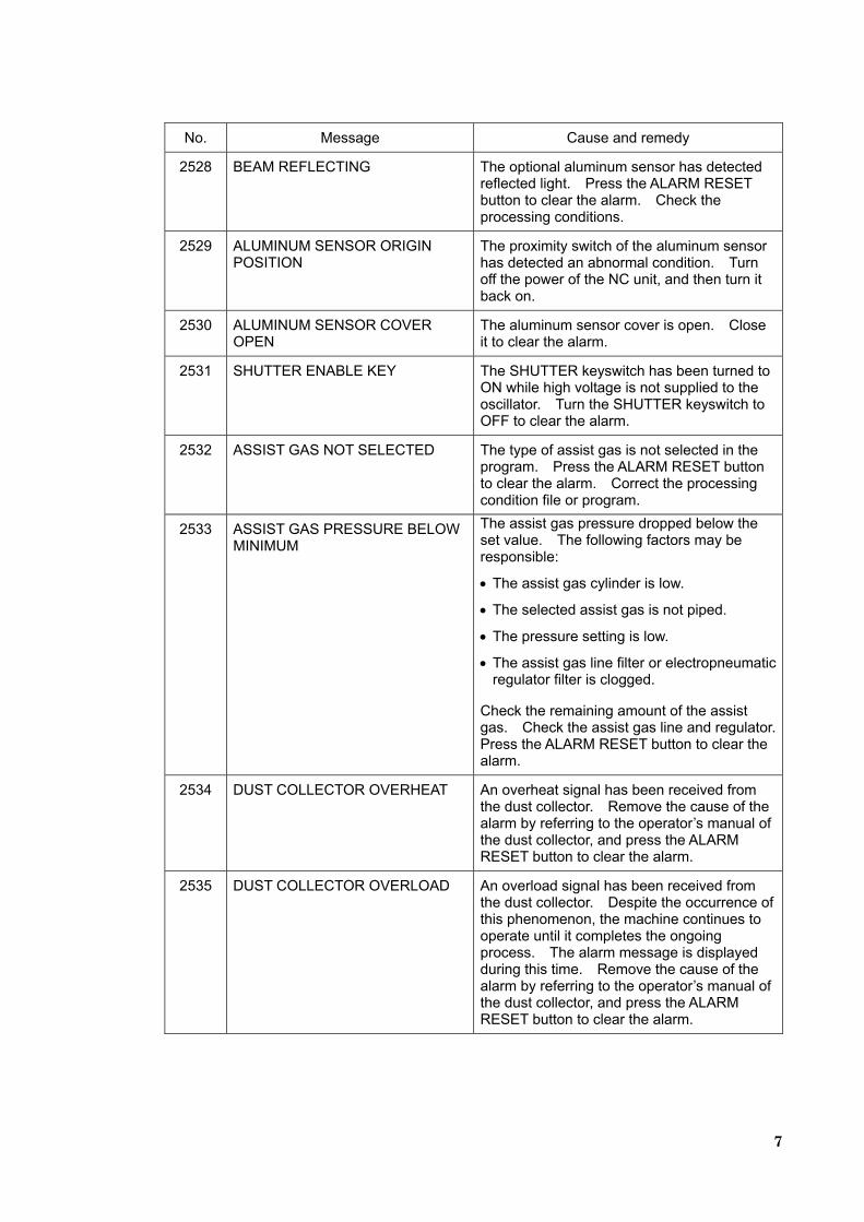
No. Message Cause and remedy
2528 BEAM REFLECTING The optional aluminum sensor has detected reflected light. Press the ALARM RESET button to clear the alarm. Check the processing conditions.
2529 ALUMINUM SENSOR ORIGIN POSITION
The proximity switch of the aluminum sensor has detected an abnormal condition. Turn off the power of the NC unit, and then turn it back on.
2530 ALUMINUM SENSOR COVER OPEN
The aluminum sensor cover is open. Close it to clear the alarm.
2531 SHUTTER ENABLE KEY The SHUTTER keyswitch has been turned to ON while high voltage is not supplied to the oscillator. Turn the SHUTTER keyswitch to OFF to clear the alarm.
2532 ASSIST GAS NOT SELECTED The type of assist gas is not selected in the program. Press the ALARM RESET button to clear the alarm. Correct the processing condition file or program.
2533 ASSIST GAS PRESSURE BELOW MINIMUM
The assist gas pressure dropped below the set value. The following factors may be responsible:
• The assist gas cylinder is low.
• The selected assist gas is not piped.
• The pressure setting is low.
• The assist gas line filter or electropneumatic regulator filter is clogged.
Check the remaining amount of the assist gas. Check the assist gas line and regulator. Press the ALARM RESET button to clear the alarm.
2534 DUST COLLECTOR OVERHEAT An overheat signal has been received from the dust collector. Remove the cause of the alarm by referring to the operator’s manual of the dust collector, and press the ALARM RESET button to clear the alarm.
2535 DUST COLLECTOR OVERLOAD An overload signal has been received from the dust collector. Despite the occurrence of this phenomenon, the machine continues to operate until it completes the ongoing process. The alarm message is displayed during this time. Remove the cause of the alarm by referring to the operator’s manual of the dust collector, and press the ALARM RESET button to clear the alarm.
8
No. Message Cause and remedy
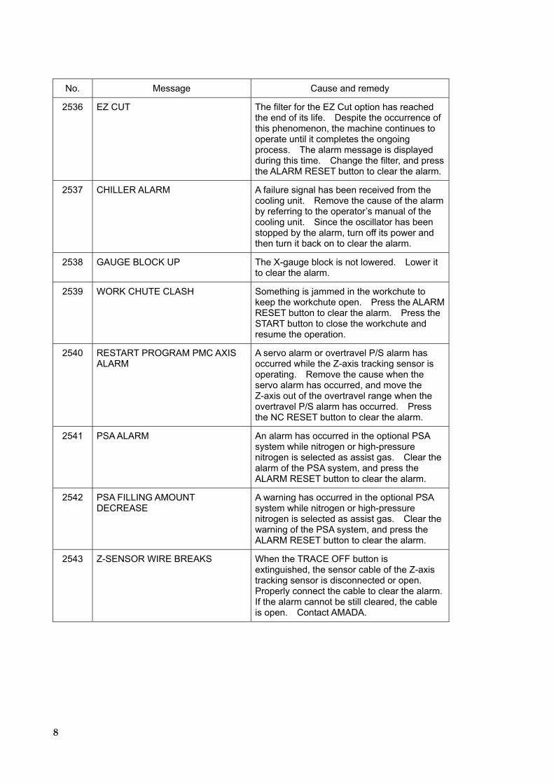
2536 EZ CUT The filter for the EZ Cut option has reached the end of its life. Despite the occurrence of this phenomenon, the machine continues to operate until it completes the ongoing process. The alarm message is displayed during this time. Change the filter, and press the ALARM RESET button to clear the alarm.
2537 CHILLER ALARM A failure signal has been received from the cooling unit. Remove the cause of the alarm by referring to the operator’s manual of the cooling unit. Since the oscillator has been stopped by the alarm, turn off its power and then turn it back on to clear the alarm.
2538 GAUGE BLOCK UP The X-gauge block is not lowered. Lower it to clear the alarm.
2539 WORK CHUTE CLASH Something is jammed in the workchute to keep the workchute open. Press the ALARM RESET button to clear the alarm. Press the START button to close the workchute and resume the operation.
2540 RESTART PROGRAM PMC AXIS ALARM
A servo alarm or overtravel P/S alarm has occurred while the Z-axis tracking sensor is operating. Remove the cause when the servo alarm has occurred, and move the Z-axis out of the overtravel range when the overtravel P/S alarm has occurred. Press the NC RESET button to clear the alarm.
2541 PSA ALARM An alarm has occurred in the optional PSA system while nitrogen or high-pressure nitrogen is selected as assist gas. Clear the alarm of the PSA system, and press the ALARM RESET button to clear the alarm.
2542 PSA FILLING AMOUNT DECREASE
A warning has occurred in the optional PSA system while nitrogen or high-pressure nitrogen is selected as assist gas. Clear the warning of the PSA system, and press the ALARM RESET button to clear the alarm.
2543 Z-SENSOR WIRE BREAKS When the TRACE OFF button is extinguished, the sensor cable of the Z-axis tracking sensor is disconnected or open. Properly connect the cable to clear the alarm. If the alarm cannot be still cleared, the cable is open. Contact AMADA.
9
No. Message Cause and remedy
2544 TRACE ERROR The laser head has risen more than 30 mm {1.2 in.} from the specified material surface during the Z-axis tracking operation, or has tried to emit the laser beam at more than 30 mm {1.2 in.} above the specified material surface. Press the ALARM RESET button to clear the alarm.
2545 LASER ALARM A failure signal has been received from the oscillator. Press the ALARM RESET button to clear the alarm. If the alarm recurs, contact AMADA.
2546 REPOSITIONING PROGRAM ERROR
Reposition is commanded when the workchute or laser shutter is open or when the laser head is located in the dead zone. Press the ALARM RESET button to clear the alarm. Correct the program.
2547 SHUTTER OPEN PROGRAM ERROR
M00 or M01 is commanded while the laser beam is emitted. Press the ALARM RESET button to clear the alarm. Correct the program.
2548 OVS PROGRAM ERROR An AIV program has an error. Press the ALARM RESET button to clear the alarm. Correct the program. An AIV command might have been specified while the workchute was open, or reposition might have been commanded while the AIV workholder was lowering.
2549 CALIBRATION FAILED The creation of the calibration data table for the Z-axis tracking sensor has failed. Press the NC RESET button to clear the alarm.
2550 CALIBRATION TIME OVER The calibration of the Z-axis tracking sensor has not been completed within the specified time. Press the NC RESET button to clear the alarm.
2551 BEAM PURGE UNIT ALARM An alarm occurred in the optional beam purge unit. Clear it to clear this alarm.
2552 OVS DEAD ZONE AIV measurement is commanded in the dead zone. Press the NC RESET button to clear the alarm. Correct the program to change the AIV measurement position.
2553 OVS CUTTING CONDITION IS WRONG
The number of cutting errors counted by the AIV cutting condition monitoring function exceeded the set value. Press the ALARM RESET button to clear the alarm. Remove the cause of the cutting errors. Before restarting the operation, reset the Allowable Bad Cut Freq. field on the AIV display.
10
No. Message Cause and remedy
2554 OVS SCRAP DROP FAILURE A scrap dropping failure has been detected by the AIV scrap drop judgment function. Press the ALARM RESET button to clear the alarm. Remove the scrap, and restart the operation.
2555 OVS EXCESSIVE ERROR OF MEASUREMENT
The hole pitch error measured with the AIV pitch error measuring function exceeded the error tolerance value. Press the ALARM RESET button to clear the alarm. Compare the Pitch Error X or Y field with the Tolerance Value field on the AIV display. Measure the amount of error by another method to check that there actually is the pitch error. The operation can be restarted.
2556 Z-AXIS NOT ORIGIN An attempt has been made to make a pallet change when the Z-axis or the ZD-axis of the optional PR-FO carriage is not at the origin. Zero-return the Z-axis or the ZD-axis, and press the ALARM RESET button to clear the alarm.
2557 WORK HOLD FAILED The workholders did not normally move down within the specified time. Contact AMADA. Press the ALARM RESET button to clear the alarm.
2558 WORK CLAMP FAILED AT REPOSITION
The workclamp close and workholder raise signals have not been completed within the specified time of 5 sec during repositioning. Contact AMADA. Press the ALARM RESET button to clear the alarm.
2559 WORK CLAMP FAILED The signal indicating the complete opening and closing of the optional pneumatic workclamps has not returned within the specified time. Contact AMADA. Press the ALARM RESET button to clear the alarm.
2560 RETRACT CLAMP FAILED The signal indicating the complete retraction has not returned within the specified time when the AVOID OFF button is extinguished. Contact AMADA. Press the ALARM RESET button to clear the alarm.
2561 WORK CHUTE CLOSE FAILED The signal indicating the complete closing of the workchute has not returned within the specified time of 8 sec after executing M81. Contact AMADA. Press the ALARM RESET button to clear the alarm.
2562 WORK CHUTE OPEN FAILED The signal indicating the complete opening of the workchute has not returned within the specified time of 8 sec after executing M80. Contact AMADA. Press the ALARM RESET button to clear the alarm.
11
No. Message Cause and remedy
2563 WORK CHUTE CYCLE FAILED The signal indicating the complete opening and closing of the workchute has not returned within the specified time of 8 sec after executing M180. Contact AMADA. Press the ALARM RESET button to clear the alarm.
2564 SHUTTER OPEN FAILED The signal indicating the complete opening of the laser shutter has not returned within the specified time after commanding the laser shutter to open. Contact AMADA. Press the NC RESET button to clear the alarm.
2565 SHUTTER CLOSE FAILED The signal indicating the complete closing of the laser shutter has not returned within the specified time after commanding the laser shutter to close. Stop the oscillator, and contact AMADA.
2566 FREE BEARING SWITCHING FAILED
The signal indicating the complete rising or lowering of the optional free-motion ball bearings has not returned within the specified time after commanding them to rise or lower. Contact AMADA. Press the ALARM RESET button to clear the alarm.
2567 RESTART PROGRAM FAILED The signal indicating the complete retrying of the Z-axis tracking sensor has not returned within the specified time. Contact AMADA. Press and illuminate the TRACE OFF button, and press the ALARM RESET button to clear the alarm.
2568 CHILLER FAILED The signal indicating the complete starting of the cooling unit has not returned with the specified time. Contact AMADA. Turn the LASER keyswitch to OFF to clear the alarm.
2569 OVS FAILED The measurement with the AIV unit has not been completed within the specified time. Press the NC RESET button to clear the alarm. If the alarm recurs, contact AMADA.
2570 DUST COLLECTOR FAILED The signal indicating the complete starting of the dust collector has not returned within the specified time after the start of the dust collector. If this phenomenon occurs during a cutting operation, the alarm is displayed when the cutting command is completed. Contact AMADA. Press the ALARM RESET button to clear the alarm.
2571 BEND MIRROR 1 MICRO SW. WELD
The signal confirming the installation position of the first bend mirror has failed. Remove the cause, and press the ALARM RESET button to clear the alarm.
12
No. Message Cause and remedy
2572 BEND MIRROR 2 MICRO SW. WELD
The signal confirming the installation position of the second bend mirror has failed. Remove the cause, and press the ALARM RESET button to clear the alarm.
2573 BEND MIRROR 3 MICRO SW. WELD
The signal confirming the installation position of the third bend mirror has failed. Remove the cause, and press the ALARM RESET button to clear the alarm.
2574 BEND MIRROR 4 MICRO SW. WELD
The signal confirming the installation position of the fourth bend mirror has failed. Remove the cause, and press the ALARM RESET button to clear the alarm.
2575 BEND MIRROR 5 MICRO SW. WELD
The signal confirming the installation position of the fifth bend mirror has failed. Remove the cause, and press the ALARM RESET button to clear the alarm.
2576 OSCILLATOR MAINTENANCE REQUIRED
The time set by the laser maintenance function has been exceeded. Since this alarm message is handled as a warning, the ongoing operation can be continued, but given the presence of a part or parts requiring maintenance, be sure to contact AMADA. The alarm message will be cleared after the maintenance by AMADA.
2577 TURBO BLOWER OVERHAUL The gas blower must be overhauled. Since this alarm message is handled as a warning, the ongoing operation can be continued, but given the presence of a part or parts requiring maintenance, be sure to contact AMADA. The alarm message will be cleared after the maintenance by AMADA.
2578 TURBO BLOWER OIL CHANGE The oil in the gas blower must be changed. Since this alarm message is handled as a warning, the ongoing operation can be continued, but given the presence of a part or parts requiring maintenance, be sure to contact AMADA. The alarm message will be cleared after the maintenance by AMADA.
2579 OSCILLATOR INTERNAL MIRROR CLEANING
The internal mirrors of the oscillator must be cleaned. Since this alarm message is handled as a warning, the ongoing operation can be continued, but given the presence of a part or parts requiring maintenance, be sure to contact AMADA. The alarm message will be cleared after the maintenance by AMADA.
13
No. Message Cause and remedy
2580 POLARIZING MIRROR CLEANING The polarizing mirror must be cleaned. Since this alarm message is handled as a warning, the ongoing operation can be continued, but given the presence of a part or parts requiring maintenance, be sure to contact AMADA. The alarm message will be cleared after the maintenance by AMADA.
2581 CHILLER COOLING WATER CHANGE
The cooling water in the cooling unit must be changed. Since this alarm message is handled as a warning, the ongoing operation can be continued, but given the presence of a part or parts requiring maintenance, be sure to contact AMADA. The alarm message will be cleared after the maintenance by AMADA.
2582 BEAM PURGE STARTING The optional beam purge unit is started. This message is displayed when the NC mode is MEMORY (DNC), the oscillator has high voltage supplied (H/V ON), the SHUTTER keyswitch is turned to ON, and the beam purge unit is not in an alarm condition. No display of the message does not mean that the beam purge unit is stopped.
2583 BEAM PURGE UNIT WARNING A warning occurred in the optional beam purge unit. Clear it to clear this alarm.
2584 NO CUTTING CONDITION FILE Not a single processing condition file is registered. Read or newly register a processing condition file or files. Press the NC RESET button to clear the alarm.
2585 NO MATERIAL REGISTERED The processing condition file specified by M102 is not registered. Register the processing condition file, or change it to one of the registered files.
2586 EMS DOES NOT SUPPORT The expanded memory is not installed, or the parameter setting is incorrect. Contact AMADA.
2587 DATA RECOVERY The processing condition file is destroyed and being restored. It was damaged by power failure, for example, during access. Wait in that condition. Completion of the restore clears the alarm.
2588 PMC/CNC WINDOW MALFUNC An abnormal condition occurred during window processing between the PMC and the CNC. Turn off the LASER keyswitch and the power of the NC unit, and then turn them back on.
2589 AUTO AGING The oscillator has entered the aging condition. This alarm message is handled as a warning. When the aging condition is completed, the alarm message is cleared.
14
No. Message Cause and remedy
2590 NC BATTERY LOW The voltage of the NC memory backup battery dropped below the specified limit. This alarm message is handled as a warning. Change the battery by referring to “Maintenance” in the operator’s manual. When the voltage returns to normal, the alarm message is cleared.
2591 LASER ALIGNMENT MODE The LASER ALIGNMENT keyswitch in the electrical control unit is turned to ON. This alarm message is handled as a warning. Turn the keyswitch to OFF to clear the alarm message.
2592 MACHINE INSPECTION MODE The MACHINE INSPECTION keyswitch in the NC control unit is turned to ON. This alarm message is handled as a warning. Turn the keyswitch to OFF to clear the alarm message.
2593 LASER WARNING A signal indicating an abnormal condition has been received from the oscillator. This alarm message is handled as a warning. Refer to the operation manual of the oscillator.
2594 EMERGENCY STOP The machine has fallen into the emergency stop condition. Clear the emergency stop condition to clear the alarm message.
2595 LASER GAS EMPTY A low pressure signal has been received from the optional laser gas cylinder residual pressure monitor. This alarm message is handled as a warning. Change the laser gas cylinder to return the laser gas pressure to normal and clear the alarm message.
2596 PROGRAM CHECK MODE The PROGRAM CHECK button is illuminated to enable the program check function. This alarm message is handled as a warning. Press and extinguish the PROGRAM CHECK button to disable the program check function and clear the alarm message.
2597 REFERENCE POSITION UNFIXED The machine has not been zero-returned in the MANUAL mode after changing from the metric mode to the inch mode or vice versa. This alarm message is handled as a warning. Change the NC mode to RETRACT, and zero-return the machine. When all axes return to the origin, the alarm message is cleared. If the machine is equipped with the B-axis, zero-return it too.
2598 MANUAL CUT MODE The MANUAL CUT keyswitch is turned to ON to enable the jog cutting function. This alarm message is handled as a warning. Turn the keyswitch to OFF to clear the alarm message.
15
No. Message Cause and remedy
2599 AMNC ACTION SIGNAL ABNORMAL
The signal indicating the operation of the AMNC has turned off. Despite the display of this alarm message, the current program continues to run. This alarm message is handled as a warning. If the alarm message is not cleared by pressing the NC RESET button, contact AMADA.
2600 PROCESS REOPENING PROHIBITION MODE
An attempt has been made to resume the operation in a mode other than PROGRAM. Close the display opened for resuming the operation, and press the ALARM RESET button to clear the alarm.
2601 LIGHT SAFETY CURTAIN DEACTIVATED
The safety device of the shuttle table has operated during a pallet change (M707 execution). Remove the cause, and press the SAFETY DEVICE RESET button on the control panel of the shuttle table to clear the alarm.
2602 BEAM COVER OPEN On the machine equipped with the optional partition, the beam cover for the alignment of the partition is open. Close the beam cover to clear the alarm.
2603 SCRAP BOX The scrap box is not properly inserted. Properly insert it to clear the alarm.
2604 ACTIVE MIRROR INTERLOCK The Active Cut mirror is not properly installed. Properly install it to clear the alarm.
2605 WORK CLAMP CLOSE An attempt has been made to raise the free-motion ball bearings when the optional pneumatic workclamps are closed. Open the workclamps, and press the ALARM RESET button to clear the alarm.
2606 ALUMINUM SENSOR The Aluminum Cut unit is abnormal when the aluminum sensor command (M734) is executed. The Aluminum Cut board is faulty, or the Aluminum Cut cable is open. Press the NC RESET button to clear the alarm, and contact AMADA.
2607 FREE BEARING UP When the optional free-motion ball bearings are raised in the table, an attempt has been made to close the workclamps or start automatic operation. Lower the free-motion ball bearings, and press the ALARM RESET button to clear the alarm.
2608 CONVEYOR OVERLOAD The conveyor is overloaded. Contact AMADA.
16
No. Message Cause and remedy
2609 PART TILT UP While the pallets are moving on the optional shuttle table, the light beams of the light curtain to detect the interference between the upper and lower pallets have been interrupted. The material on the lower pallet may be bowed. Remove the cause, and press the ALARM RESET button to clear the alarm.
2610 LASER POWER OFF The power of the oscillator is turned off. This alarm message is handled as a warning. Turn the LASER keyswitch to OFF, and turn on the power of the oscillator.
2611 WORK CLAMP AIR COUPLER When the optional pneumatic workclamps open and close, compressed air is not supplied to the air coupler of the pallet. Turn the air coupler to the supply position, supply compressed air to the air coupler, and press the ALARM RESET button to clear the alarm.
2612 INDEXING UNIT NOT ORIGIN When the optional pipe indexing unit is not in the store position, all pallets have not been placed in the shuttle, or an attempt has been made to start jog cutting. Fix the pipe indexing unit in the store position, and press the ALARM RESET button to clear the alarm.
2613 WORK SET NOT READY On the machine equipped with the optional shuttle table, a pallet change (M707) was commanded when the WORK SET READY light is not illuminated on the control panel of the shuttle table. Press the ALARM RESET button to clear the alarm. Press the WORK SET READY button on the control panel of the shuttle table, and command a pallet change.
2614 TABLE EXCHANGE FAILED The signal indicating the completion of pallet change on the optional shuttle table has not returned within the specified time. Contact AMADA. Press the ALARM RESET button to clear the alarm.
2615 PALLET LOCK FAILED ON MACHINE
The signal indicating the completion of pallet origin lock pin operation on the optional shuttle table has not returned within the specified time. Contact AMADA. Press the ALARM RESET button to clear the alarm.
2616 PALLET LOCK FAILED ON SHUTTLE
The signal indicating the completion of pallet home lock pin operation on the optional shuttle table has not returned within the specified time. Contact AMADA. Press the ALARM RESET button to clear the alarm.
17
No. Message Cause and remedy
2617 SHEET LIFT DEVICE FAILED The signal indicating the completion of lifter operation on the optional shuttle table has not returned within the specified time. Contact AMADA. Press the ALARM RESET button to clear the alarm.
2618 SHUTTLE DOOR OPEN/CLOSE FAILED
The signal indicating the completion of safety shutter operation on the optional shuttle table has not returned within the specified time. Contact AMADA. Press the ALARM RESET button to clear the alarm.
2619 CLAMP AIR SUPPLY FAILED ON MACHINE
The signal indicating the completion of clamp air supply block operation on the optional shuttle table has not returned within the specified time. Contact AMADA. Press the ALARM RESET button to clear the alarm.
2620 ACTIVE MIRROR MICRO SW. WELD
The signal confirming the installation of the Active Cut mirror has failed. Contact AMADA. Press the ALARM RESET button to clear the alarm.
2621 PALLET POSITION A command has been specified to raise or lower a pallet when the pallet is not at the origin or home position on the machine equipped with the optional shuttle table, or to move the pallet when the pallet is not at the upper or lower end. Press the ALARM RESET button to clear the alarm. Move the pallet to the origin or home position, or to the upper or lower end, and continue on to the next operation.
2622 INVERTER ALARM The traverser forward/backward inverter of the optional shuttle table has encountered an alarm condition. Contact AMADA. Check the inverter indicator in the electrical control cabinet of the shuttle table, remove the cause of the alarm, and press the NC RESET button to clear the alarm.
2623 WORK STOPPER UP The work stopper is not at the lower end when the free-motion ball bearings are at the lower end on the optional shuttle table. Press the ALARM RESET button to clear the alarm. Move the free-motion ball bearings or work stopper, depending on the purpose of operation.
2624 SHUTTLE DOOR IS OPEN The MEMORY mode has been selected when the safety shutter is open on the machine equipped with the optional shuttle table. Select the MANUAL mode to clear the alarm. Close the safety shutter.
18
No. Message Cause and remedy
2625 SHUTTLE DOOR IS CLOSED An attempt has been made to move the pallet in the MANUAL mode when the safety shutter is closed on the machine equipped with the optional shuttle table. Press the ALARM RESET button to clear the alarm. Open the safety shutter in the MANUAL mode.
2626 SHUTTLE SHORT BAR MISS The short bar setting on the optional shuttle table is abnormal. Remove the cause, and press the ALARM RESET button to clear the alarm.
2627 TABLE CIRCUIT PROTECTOR TRIP
The thermal relay of the lifter or traverser motor on the optional shuttle table has tripped. If the cause of the trip is not known, contact AMADA.
2628 PALLET SHOT PIN IN FAILED The insertion of the LST pallet shot pin has not been completed within the specified time. If the alarm recurs, contact AMADA.
2629 PALLET SHOT PIN OUT FAILED The withdrawal of the LST pallet shot pin has not been completed within the specified time. If the alarm recurs, contact AMADA.
2630 PALLET DOWN OVER TRAVEL The LST pallet has overtraveled in the downward direction. If the alarm recurs, contact AMADA.
2631 SHUTTLE DOOR IS CLOSE An attempt has been made to move the pallet in the MANUAL mode when the safety shutter is closed on the machine equipped with the optional shuttle table. Press the ALARM RESET button to clear the alarm. Open the safety shutter in the MANUAL mode.
2632 THIS MACHINE IS NOT LST The ID recognition jumper of the LST specification is not set. Contact AMADA.
2633 LST PALLET NOT CHANGE The pallet change M-code has never been commanded after execution of the LST schedule start M-code. Correct the program.
2645 X-AXIS SYNCHRONOUS CONTROL OFF
The keep relay for maintenance is turned on. This alarm message is handled as a warning. Contact AMADA.
2646 X-AXIS IS IN SAFE AREA The X-axis has entered the safety area. This alarm message is handled as a warning. Change the NC mode to MANUAL, and press the –X button to move the X-axis out of the safety area and clear the alarm.
2647 PROGRAM FORWARD UNFINISH The START button has been pressed while the program edited on the touch screen is being transferred to the NC unit. This alarm message is handled as a warning. Press the NC RESET button to clear the alarm.
19
No. Message Cause and remedy
2648 LASER ALIGNMENT MODE SWITCH OFF
An attempt has been made to perform the laser beam-out function on the Beam-out display among the UTILITY displays, but the LASER ALIGNMENT keyswitch is turned to OFF. Turn the LASER ALIGNMENT keyswitch to ON, and press the ALARM RESET button to clear the alarm.
2649 PROCESS REOPENING START PROHIBITION
The START button has been pressed to resume the cutting operation when the RESUME button in the Resume box is extinguished. Press the ALARM RESET button to clear the alarm. Press and illuminate the RESUME button, and press the START button.
2650 RETRY START PROHIBITION The START button has been pressed to perform the retry operation when none of the function selection buttons is illuminated on the display where the retry operation is to be performed. Press the ALARM RESET button to clear the alarm. Press and illuminate one of the function selection buttons, and press the START button.
2651 AMNC DATA MAINTENANCE MODE
The AMNC has been placed in the data maintenance mode. This alarm message is handled as a warning. Contact AMADA.
2652 DUST COLLECTOR N2 GAS DECREASE
This warning message occurs when the pressure of the cylinder containing nitrogen gas for use in the dust collector for fire prevention is low. Change the cylinder.
2653 DUST COLLECTOR N2 GAS LOWER LIMIT
This warning message occurs when the pressure of the cylinder containing nitrogen gas for use in the dust collector for fire prevention reaches the lower limit. Change the cylinder.
2654 SCHEDULE INTERRUPT Schedule operation was interrupted. This alarm message is handled as a warning. Press the ALARM RESET button to clear the alarm.
2655 SCHEDULE START EXCLUDING SCHEDULE MODE
The START button has been pressed to perform schedule operation when the SCHEDULE button is not pressed yet. Press the NC RESET button to clear the alarm. Press the SCHEDULE button and the START button.
2656 X-AXIS APERTURE OVERHEAT The X-axis aperture is overheated.
Contact AMADA.
20
No. Message Cause and remedy
2657 Y-AXIS APERTURE OVERHEAT The Y-axis aperture is overheated.
Contact AMADA.
2658 Z-AXIS APERTURE OVERHEAT The Z-axis aperture is overheated.
Contact AMADA.
2659 PC COMMUNICATION ABNORMAL A communication error occurred between the PMC and PC during data processing. Turn off the power of the NC unit, and then turn it back on.
2660 X1 MOTOR OVERHEAT The X-axis front motor is overheated.
Contact AMADA.
2661 X2 MOTOR OVERHEAT The X-axis rear motor is overheated.
Contact AMADA.
2662 Y MOTOR OVERHEAT The Y-axis motor is overheated.
Contact AMADA.
2663 Z MOTOR OVERHEAT The Z-axis motor is overheated.
Contact AMADA.
2664 OVER TRAVEL +X The X-axis exceeded the plus axis travel range.
Change the NC mode to MANUAL, and while pressing the OT RELEASE button, press the –X button to move the X-axis in the minus direction. The alarm is cleared.
2665 OVER TRAVEL -X The X-axis exceeded the minus axis travel range.
Change the NC mode to MANUAL, and while pressing the OT RELEASE button, press the +X button to move the X-axis in the plus direction. The alarm is cleared.
2666 OVER TRAVEL +Y The Y-axis exceeded the plus axis travel range.
Change the NC mode to MANUAL, and while pressing the OT RELEASE button, press the –Y button to move the Y-axis in the minus direction. The alarm is cleared.
2667 OVER TRAVEL -Y The Y-axis exceeded the minus axis travel range.
Change the NC mode to MANUAL, and while pressing the OT RELEASE button, press the +Y button to move the Y-axis in the plus direction. The alarm is cleared.
21
No. Message Cause and remedy
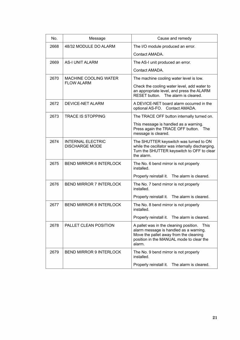
2668 48/32 MODULE DO ALARM The I/O module produced an error.
Contact AMADA.
2669 AS-I UNIT ALARM The AS-I unit produced an error.
Contact AMADA.
2670 MACHINE COOLING WATER FLOW ALARM
The machine cooling water level is low.
Check the cooling water level, add water to an appropriate level, and press the ALARM RESET button. The alarm is cleared.
2672 DEVICE-NET ALARM A DEVICE-NET board alarm occurred in the optional AS-FO. Contact AMADA.
2673 TRACE IS STOPPING The TRACE OFF button internally turned on.
This message is handled as a warning. Press again the TRACE OFF button. The message is cleared.
2674 INTERNAL ELECTRIC DISCHARGE MODE
The SHUTTER keyswitch was turned to ON while the oscillator was internally discharging. Turn the SHUTTER keyswitch to OFF to clear the alarm.
2675 BEND MIRROR 6 INTERLOCK The No. 6 bend mirror is not properly installed.
Properly reinstall it. The alarm is cleared.
2676 BEND MIRROR 7 INTERLOCK The No. 7 bend mirror is not properly installed.
Properly reinstall it. The alarm is cleared.
2677 BEND MIRROR 8 INTERLOCK The No. 8 bend mirror is not properly installed.
Properly reinstall it. The alarm is cleared.
2678 PALLET CLEAN POSITION A pallet was in the cleaning position. This alarm message is handled as a warning. Move the pallet away from the cleaning position in the MANUAL mode to clear the alarm.
2679 BEND MIRROR 9 INTERLOCK The No. 9 bend mirror is not properly installed.
Properly reinstall it. The alarm is cleared.
22
No. Message Cause and remedy
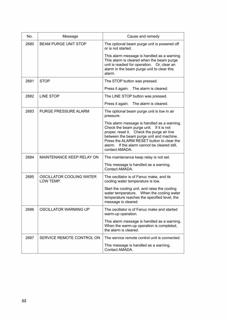
2680 BEAM PURGE UNIT STOP The optional beam purge unit is powered off or is not started.
This alarm message is handled as a warning. This alarm is cleared when the beam purge unit is readied for operation. Or, clear an alarm in the beam purge unit to clear this alarm.
2681 STOP The STOP button was pressed.
Press it again. The alarm is cleared.
2682 LINE STOP The LINE STOP button was pressed.
Press it again. The alarm is cleared.
2683 PURGE PRESSURE ALARM The optional beam purge unit is low in air pressure.
This alarm message is handled as a warning. Check the beam purge unit. If it is not proper, reset it. Check the purge air line between the beam purge unit and machine. Press the ALARM RESET button to clear the alarm. If the alarm cannot be cleared still, contact AMADA.
2684 MAINTENANCE KEEP RELAY ON The maintenance keep relay is not set.
This message is handled as a warning. Contact AMADA.
2685 OSCILLATOR COOLING WATER LOW TEMP.
The oscillator is of Fanuc make, and its cooling water temperature is low.
Start the cooling unit, and raise the cooling water temperature. When the cooling water temperature reaches the specified level, the message is cleared.
2686 OSCILLATOR WARMING UP The oscillator is of Fanuc make and started warm-up operation.
This alarm message is handled as a warning. When the warm-up operation is completed, the alarm is cleared.
2687 SERVICE REMOTE CONTROL ON The service remote control unit is connected.
This message is handled as a warning. Contact AMADA.
23
No. Message Cause and remedy
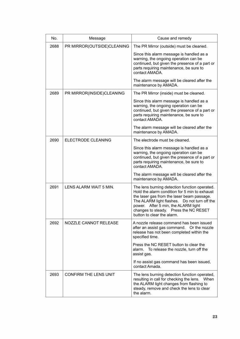
2688 PR MIRROR(OUTSIDE)CLEANING The PR Mirror (outside) must be cleaned.
Since this alarm message is handled as a warning, the ongoing operation can be continued, but given the presence of a part or parts requiring maintenance, be sure to contact AMADA.
The alarm message will be cleared after the maintenance by AMADA.
2689 PR MIRROR(INSIDE)CLEANING The PR Mirror (inside) must be cleaned.
Since this alarm message is handled as a warning, the ongoing operation can be continued, but given the presence of a part or parts requiring maintenance, be sure to contact AMADA.
The alarm message will be cleared after the maintenance by AMADA.
2690 ELECTRODE CLEANING The electrode must be cleaned.
Since this alarm message is handled as a warning, the ongoing operation can be continued, but given the presence of a part or parts requiring maintenance, be sure to contact AMADA.
The alarm message will be cleared after the maintenance by AMADA.
2691 LENS ALARM WAIT 5 MIN. The lens burning detection function operated. Hold the alarm condition for 5 min to exhaust the laser gas from the laser beam passage. The ALARM light flashes. Do not turn off the power. After 5 min, the ALARM light changes to steady. Press the NC RESET button to clear the alarm.
2692 NOZZLE CANNOT RELEASE A nozzle release command has been issued after an assist gas command. Or the nozzle release has not been completed within the specified time.
Press the NC RESET button to clear the alarm. To release the nozzle, turn off the assist gas.
If no assist gas command has been issued, contact Amada.
2693 CONFIRM THE LENS UNIT The lens burning detection function operated, resulting in call for checking the lens. When the ALARM light changes from flashing to steady, remove and check the lens to clear the alarm.
24
No. Message Cause and remedy
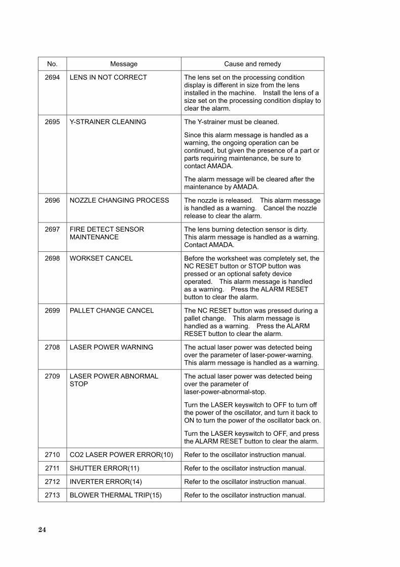
2694 LENS IN NOT CORRECT The lens set on the processing condition display is different in size from the lens installed in the machine. Install the lens of a size set on the processing condition display to clear the alarm.
2695 Y-STRAINER CLEANING The Y-strainer must be cleaned.
Since this alarm message is handled as a warning, the ongoing operation can be continued, but given the presence of a part or parts requiring maintenance, be sure to contact AMADA.
The alarm message will be cleared after the maintenance by AMADA.
2696 NOZZLE CHANGING PROCESS The nozzle is released. This alarm message is handled as a warning. Cancel the nozzle release to clear the alarm.
2697 FIRE DETECT SENSOR MAINTENANCE
The lens burning detection sensor is dirty. This alarm message is handled as a warning. Contact AMADA.
2698 WORKSET CANCEL Before the worksheet was completely set, the NC RESET button or STOP button was pressed or an optional safety device operated. This alarm message is handled as a warning. Press the ALARM RESET button to clear the alarm.
2699 PALLET CHANGE CANCEL The NC RESET button was pressed during a pallet change. This alarm message is handled as a warning. Press the ALARM RESET button to clear the alarm.
2708 LASER POWER WARNING The actual laser power was detected being over the parameter of laser-power-warning. This alarm message is handled as a warning.
2709 LASER POWER ABNORMAL STOP
The actual laser power was detected being over the parameter of laser-power-abnormal-stop.
Turn the LASER keyswitch to OFF to turn off the power of the oscillator, and turn it back to ON to turn the power of the oscillator back on.
Turn the LASER keyswitch to OFF, and press the ALARM RESET button to clear the alarm.
2710 CO2 LASER POWER ERROR(10) Refer to the oscillator instruction manual.
2711 SHUTTER ERROR(11) Refer to the oscillator instruction manual.
2712 INVERTER ERROR(14) Refer to the oscillator instruction manual.
2713 BLOWER THERMAL TRIP(15) Refer to the oscillator instruction manual.
25
No. Message Cause and remedy
2714 EVACUATION FAULT(17) Refer to the oscillator instruction manual.
2715 EVACUATION PUMP THERMAL TRIP(18)
Refer to the oscillator instruction manual.
2716 GAS CHANGE FAULT(LOW)(19) Refer to the oscillator instruction manual.
2717 LASER GAS PRESSURE ERROR(20)
Refer to the oscillator instruction manual.
2718 GAS CHANGE INCOMPLETE(21) Refer to the oscillator instruction manual.
2719 POWER DAMPER ERROR(25) Refer to the oscillator instruction manual.
2720 BEAM ON PROTECT ERR(26) Refer to the oscillator instruction manual.
2721 COOLING UNIT FAULT(30) Refer to the cooling unit instruction manual.
2722 WATER QUALITY ERROR(CONDUCTIVITY)(31)
Refer to the cooling unit instruction manual.
2723 COOLING WATER TEMPERATURE ERROR(33)
Refer to the cooling unit instruction manual.
2724 COLD WATER TEMPERATURE ERROR(34)
Refer to the cooling unit instruction manual.
2725 WAIT FOR RECOVERY WITH ION EXCHANGE(35)
Refer to the cooling unit instruction manual.
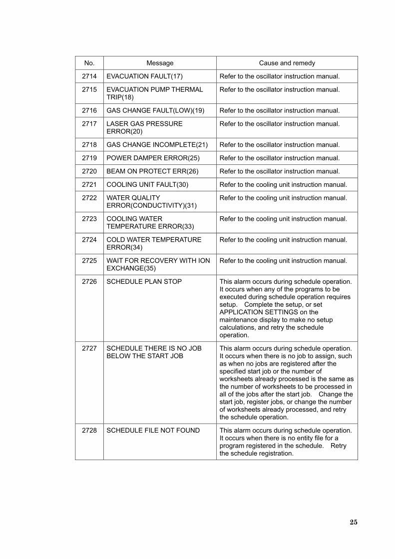
2726 SCHEDULE PLAN STOP This alarm occurs during schedule operation. It occurs when any of the programs to be executed during schedule operation requires setup. Complete the setup, or set APPLICATION SETTINGS on the maintenance display to make no setup calculations, and retry the schedule operation.
2727 SCHEDULE THERE IS NO JOB BELOW THE START JOB
This alarm occurs during schedule operation. It occurs when there is no job to assign, such as when no jobs are registered after the specified start job or the number of worksheets already processed is the same as the number of worksheets to be processed in all of the jobs after the start job. Change the start job, register jobs, or change the number of worksheets already processed, and retry the schedule operation.
2728 SCHEDULE FILE NOT FOUND This alarm occurs during schedule operation. It occurs when there is no entity file for a program registered in the schedule. Retry the schedule registration.
26
No. Message Cause and remedy
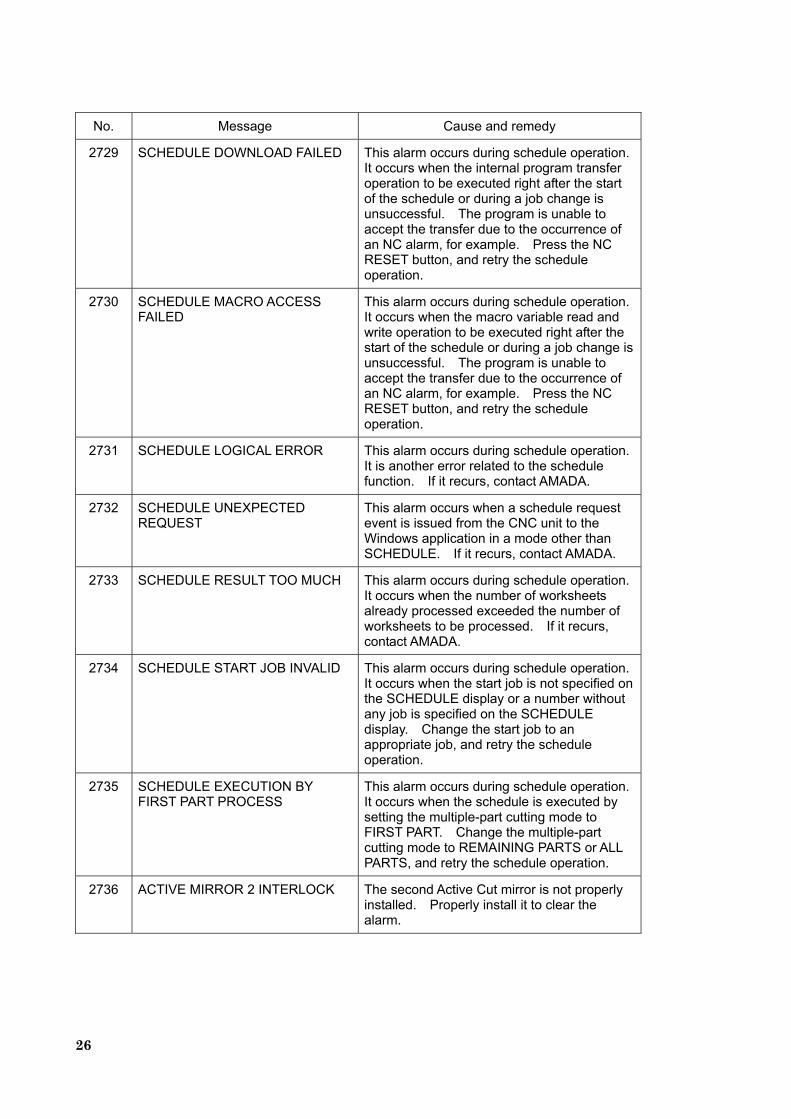
2729 SCHEDULE DOWNLOAD FAILED This alarm occurs during schedule operation. It occurs when the internal program transfer operation to be executed right after the start of the schedule or during a job change is unsuccessful. The program is unable to accept the transfer due to the occurrence of an NC alarm, for example. Press the NC RESET button, and retry the schedule operation.
2730 SCHEDULE MACRO ACCESS FAILED
This alarm occurs during schedule operation. It occurs when the macro variable read and write operation to be executed right after the start of the schedule or during a job change is unsuccessful. The program is unable to accept the transfer due to the occurrence of an NC alarm, for example. Press the NC RESET button, and retry the schedule operation.
2731 SCHEDULE LOGICAL ERROR This alarm occurs during schedule operation. It is another error related to the schedule function. If it recurs, contact AMADA.
2732 SCHEDULE UNEXPECTED REQUEST
This alarm occurs when a schedule request event is issued from the CNC unit to the Windows application in a mode other than SCHEDULE. If it recurs, contact AMADA.
2733 SCHEDULE RESULT TOO MUCH This alarm occurs during schedule operation. It occurs when the number of worksheets already processed exceeded the number of worksheets to be processed. If it recurs, contact AMADA.
2734 SCHEDULE START JOB INVALID This alarm occurs during schedule operation. It occurs when the start job is not specified on the SCHEDULE display or a number without any job is specified on the SCHEDULE display. Change the start job to an appropriate job, and retry the schedule operation.
2735 SCHEDULE EXECUTION BY FIRST PART PROCESS
This alarm occurs during schedule operation. It occurs when the schedule is executed by setting the multiple-part cutting mode to FIRST PART. Change the multiple-part cutting mode to REMAINING PARTS or ALL PARTS, and retry the schedule operation.
2736 ACTIVE MIRROR 2 INTERLOCK The second Active Cut mirror is not properly installed. Properly install it to clear the alarm.

27
No. Message Cause and remedy
2737 OIL SHOT OIL LOWER LIMIT The level of the shot agent No. 9 for the oil shot is low. This message is handled as a warning.
Add the shot agent No. 9 to the shot tank. Press the ALARM RESET button to clear the alarm.
2738 NOZZLE CLEANER FAILED The nozzle cleaner door does not operate properly.
Check the nozzle cleaner door. If something is stuck in the door, turn off the compressed air, and remove it.
If a buildup of dust and the like does not allow the nozzle cleaner door to operate properly, clean the door.
If the air supply pressure is too low for the nozzle cleaner door to operate properly, check that the main air pressure is proper.
If this alarm occurs although the main air pressure is normal, contact AMADA.
Press the ALARM RESET button to clear the alarm.
2739 NOZZLE CLEANER CRASH POSITION
The program operation of the machine was performed with the nozzle cleaner door open.
Change the NC mode to RETRACT, and zero-return the Z-axis. When the zero-return of the Z-axis is completed, the alarm is cleared.
After the alarm is cleared, close the nozzle cleaner door.
2740 COLD WATER TEMPERATURE STABILITY WAIT(36)
Refer to the cooling unit instruction manual.
2741 CONDUCTIVITY WARNING(37) Refer to the cooling unit instruction manual.
2742 CO2 LASER COOLING WATER LEAK(79)
Refer to the oscillator instruction manual.
2743 COOLING WATER TEMPERATURE STABILITY WAIT(80)
Refer to the cooling unit instruction manual.
2744 PATLITE RAN DOWN The light bulb of the oscillator patlite ran down. Replace the light bulb.
28
No. Message Cause and remedy
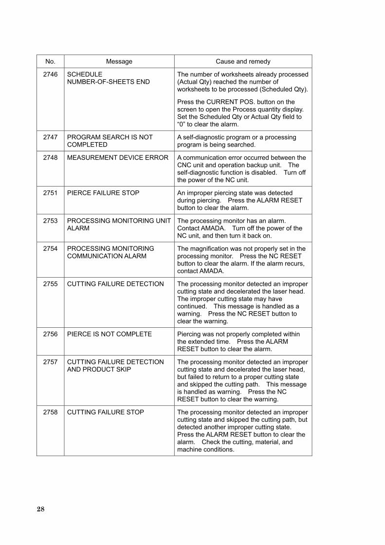
2746 SCHEDULE NUMBER-OF-SHEETS END
The number of worksheets already processed (Actual Qty) reached the number of worksheets to be processed (Scheduled Qty).
Press the CURRENT POS. button on the screen to open the Process quantity display. Set the Scheduled Qty or Actual Qty field to “0” to clear the alarm.
2747 PROGRAM SEARCH IS NOT COMPLETED
A self-diagnostic program or a processing program is being searched.
2748 MEASUREMENT DEVICE ERROR A communication error occurred between the CNC unit and operation backup unit. The self-diagnostic function is disabled. Turn off the power of the NC unit.
2751 PIERCE FAILURE STOP An improper piercing state was detected during piercing. Press the ALARM RESET button to clear the alarm.
2753 PROCESSING MONITORING UNIT ALARM
The processing monitor has an alarm. Contact AMADA. Turn off the power of the NC unit, and then turn it back on.
2754 PROCESSING MONITORING COMMUNICATION ALARM
The magnification was not properly set in the processing monitor. Press the NC RESET button to clear the alarm. If the alarm recurs, contact AMADA.
2755 CUTTING FAILURE DETECTION The processing monitor detected an improper cutting state and decelerated the laser head. The improper cutting state may have continued. This message is handled as a warning. Press the NC RESET button to clear the warning.
2756 PIERCE IS NOT COMPLETE Piercing was not properly completed within the extended time. Press the ALARM RESET button to clear the alarm.
2757 CUTTING FAILURE DETECTION AND PRODUCT SKIP
The processing monitor detected an improper cutting state and decelerated the laser head, but failed to return to a proper cutting state and skipped the cutting path. This message is handled as warning. Press the NC RESET button to clear the warning.
2758 CUTTING FAILURE STOP The processing monitor detected an improper cutting state and skipped the cutting path, but detected another improper cutting state. Press the ALARM RESET button to clear the alarm. Check the cutting, material, and machine conditions.
29
No. Message Cause and remedy
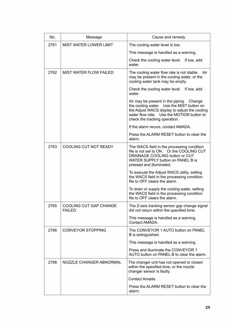
2761 MIST WATER LOWER LIMIT The cooling water level is low.
This message is handled as a warning.
Check the cooling water level. If low, add water.
2762 MIST WATER FLOW FAILED The cooling water flow rate is not stable. Air may be present in the cooling water, or the cooling water tank may be empty.
Check the cooling water level. If low, add water.
Air may be present in the piping. Change the cooling water. Use the MIST button on the Adjust WACS display to adjust the cooling water flow rate. Use the MOTION button to check the tracking operation.
If the alarm recurs, contact AMADA.
Press the ALARM RESET button to clear the alarm.
2763 COOLING CUT NOT READY The WACS field in the processing condition file is not set to ON. Or the COOLING CUT DRAINAGE COOLING button or CUT WATER SUPPLY button on PANEL B is pressed and illuminated.
To execute the Adjust WACS utility, setting the WACS field in the processing condition file to OFF clears the alarm.
To drain or supply the cooling water, setting the WACS field in the processing condition file to OFF clears the alarm.
2765 COOLING CUT GAP CHANGE FAILED
The Z-axis tracking sensor gap change signal did not return within the specified time.
This message is handled as a warning. Contact AMADA.
2766 CONVEYOR STOPPING The CONVEYOR 1 AUTO button on PANEL B is extinguished.
This message is handled as a warning.
Press and illuminate the CONVEYOR 1 AUTO button on PANEL B to clear the alarm.
2768 NOZZLE CHANGER ABNORMAL The changer unit has not opened or closed within the specified time, or the nozzle changer sensor is faulty.
Contact Amada.
Press the ALARM RESET button to clear the alarm.
30
No. Message Cause and remedy
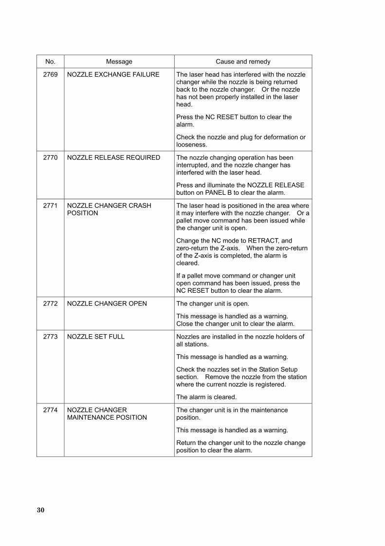
2769 NOZZLE EXCHANGE FAILURE The laser head has interfered with the nozzle changer while the nozzle is being returned back to the nozzle changer. Or the nozzle has not been properly installed in the laser head.
Press the NC RESET button to clear the alarm.
Check the nozzle and plug for deformation or looseness.
2770 NOZZLE RELEASE REQUIRED The nozzle changing operation has been interrupted, and the nozzle changer has interfered with the laser head.
Press and illuminate the NOZZLE RELEASE button on PANEL B to clear the alarm.
2771 NOZZLE CHANGER CRASH POSITION
The laser head is positioned in the area where it may interfere with the nozzle changer. Or a pallet move command has been issued while the changer unit is open.
Change the NC mode to RETRACT, and zero-return the Z-axis. When the zero-return of the Z-axis is completed, the alarm is cleared.
If a pallet move command or changer unit open command has been issued, press the NC RESET button to clear the alarm.
2772 NOZZLE CHANGER OPEN The changer unit is open.
This message is handled as a warning. Close the changer unit to clear the alarm.
2773 NOZZLE SET FULL Nozzles are installed in the nozzle holders of all stations.
This message is handled as a warning.
Check the nozzles set in the Station Setup section. Remove the nozzle from the station where the current nozzle is registered.
The alarm is cleared.
2774 NOZZLE CHANGER MAINTENANCE POSITION
The changer unit is in the maintenance position.
This message is handled as a warning.
Return the changer unit to the nozzle change position to clear the alarm.
31
No. Message Cause and remedy
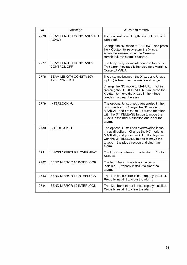
2776 BEAM LENGTH CONSTANCY NOT READY
The constant beam length control function is turned off.
Change the NC mode to RETRACT and press the +X button to zero-return the X-axis. When the zero-return of the X-axis is completed, the alarm is cleared.
2777 BEAM LENGTH CONSTANCY CONTROL OFF
The keep relay for maintenance is turned on. This alarm message is handled as a warning. Contact AMADA.
2778 BEAM LENGTH CONSTANCY AXIS CONFLICT
The distance between the X-axis and U-axis (option) is less than the axis travel range.
Change the NC mode to MANUAL. While pressing the OT RELEASE button, press the – X button to move the X-axis in the minus direction to clear the alarm.
2779 INTERLOCK +U The optional U-axis has overtraveled in the plus direction. Change the NC mode to MANUAL, and press the –U button together with the OT RELEASE button to move the U-axis in the minus direction and clear the alarm.
2780 INTERLOCK –U The optional U-axis has overtraveled in the minus direction. Change the NC mode to MANUAL, and press the +U button together with the OT RELEASE button to move the U-axis in the plus direction and clear the alarm.
2781 U-AXIS APERTURE OVERHEAT The U-axis aperture is overheated. Contact AMADA.
2782 BEND MIRROR 10 INTERLOCK The tenth bend mirror is not properly installed. Properly install it to clear the alarm.
2783 BEND MIRROR 11 INTERLOCK The 11th bend mirror is not properly installed. Properly install it to clear the alarm.
2784 BEND MIRROR 12 INTERLOCK The 12th bend mirror is not properly installed. Properly install it to clear the alarm.
32
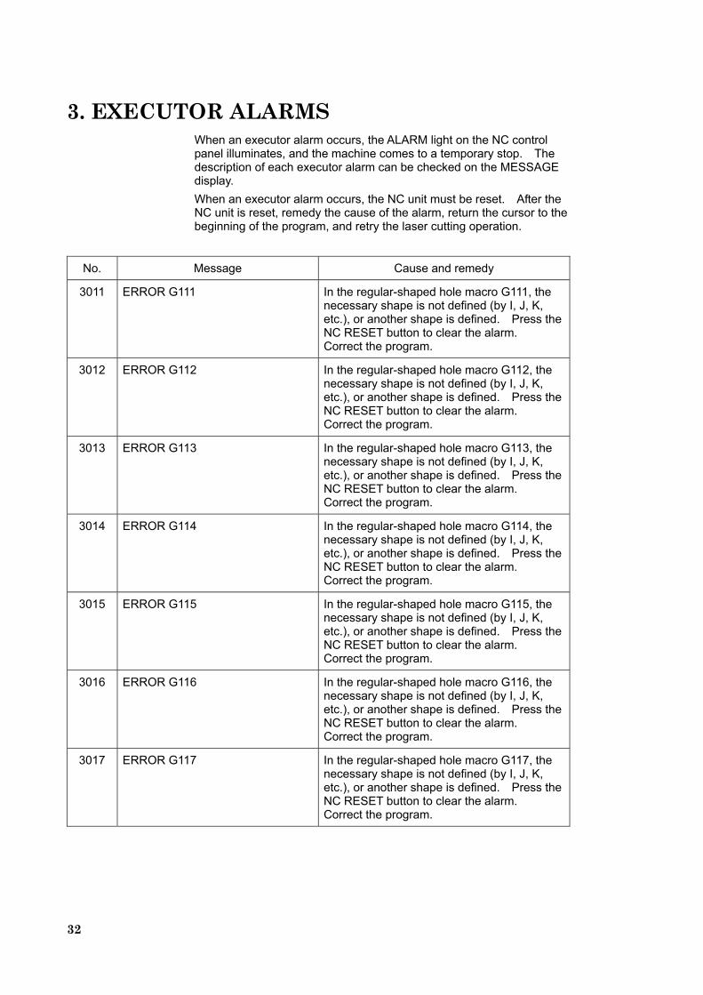
3. EXECUTOR ALARMS When an executor alarm occurs, the ALARM light on the NC control panel illuminates, and the machine comes to a temporary stop. The description of each executor alarm can be checked on the MESSAGE display. When an executor alarm occurs, the NC unit must be reset. After the NC unit is reset, remedy the cause of the alarm, return the cursor to the beginning of the program, and retry the laser cutting operation.
No. Message Cause and remedy
3011 ERROR G111 In the regular-shaped hole macro G111, the necessary shape is not defined (by I, J, K, etc.), or another shape is defined. Press the NC RESET button to clear the alarm. Correct the program.
3012 ERROR G112 In the regular-shaped hole macro G112, the necessary shape is not defined (by I, J, K, etc.), or another shape is defined. Press the NC RESET button to clear the alarm. Correct the program.
3013 ERROR G113 In the regular-shaped hole macro G113, the necessary shape is not defined (by I, J, K, etc.), or another shape is defined. Press the NC RESET button to clear the alarm. Correct the program.
3014 ERROR G114 In the regular-shaped hole macro G114, the necessary shape is not defined (by I, J, K, etc.), or another shape is defined. Press the NC RESET button to clear the alarm. Correct the program.
3015 ERROR G115 In the regular-shaped hole macro G115, the necessary shape is not defined (by I, J, K, etc.), or another shape is defined. Press the NC RESET button to clear the alarm. Correct the program.
3016 ERROR G116 In the regular-shaped hole macro G116, the necessary shape is not defined (by I, J, K, etc.), or another shape is defined. Press the NC RESET button to clear the alarm. Correct the program.
3017 ERROR G117 In the regular-shaped hole macro G117, the necessary shape is not defined (by I, J, K, etc.), or another shape is defined. Press the NC RESET button to clear the alarm. Correct the program.
33
No. Message Cause and remedy
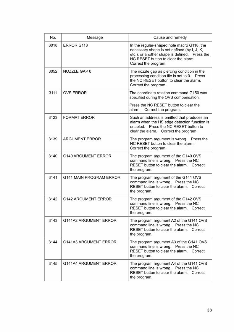
3018 ERROR G118 In the regular-shaped hole macro G118, the necessary shape is not defined (by I, J, K, etc.), or another shape is defined. Press the NC RESET button to clear the alarm. Correct the program.
3052 NOZZLE GAP 0 The nozzle gap as piercing condition in the processing condition file is set to 0. Press the NC RESET button to clear the alarm. Correct the program.
3111 OVS ERROR The coordinate rotation command G150 was specified during the OVS compensation.
Press the NC RESET button to clear the alarm. Correct the program.
3123 FORMAT ERROR Such an address is omitted that produces an alarm when the HS edge detection function is enabled. Press the NC RESET button to clear the alarm. Correct the program.
3139 ARGUMENT ERROR The program argument is wrong. Press the NC RESET button to clear the alarm. Correct the program.
3140 G140 ARGUMENT ERROR The program argument of the G140 OVS command line is wrong. Press the NC RESET button to clear the alarm. Correct the program.
3141 G141 MAIN PROGRAM ERROR The program argument of the G141 OVS command line is wrong. Press the NC RESET button to clear the alarm. Correct the program.
3142 G142 ARGUMENT ERROR The program argument of the G142 OVS command line is wrong. Press the NC RESET button to clear the alarm. Correct the program.
3143 G141A2 ARGUMENT ERROR The program argument A2 of the G141 OVS command line is wrong. Press the NC RESET button to clear the alarm. Correct the program.
3144 G141A3 ARGUMENT ERROR The program argument A3 of the G141 OVS command line is wrong. Press the NC RESET button to clear the alarm. Correct the program.
3145 G141A4 ARGUMENT ERROR The program argument A4 of the G141 OVS command line is wrong. Press the NC RESET button to clear the alarm. Correct the program.
34
No. Message Cause and remedy
3146 G141A5 ARGUMENT ERROR The program argument A5 of the G141 OVS command line is wrong. Press the NC RESET button to clear the alarm. Correct the program.
3147 G141A6 ARGUMENT ERROR The program argument A6 of the G141 OVS command line is wrong. Press the NC RESET button to clear the alarm. Correct the program.
3148 G143 ARGUMENT ERROR The program argument of the G143 OVS command line is wrong. Press the NC RESET button to clear the alarm. Correct the program.
3149 1111 FLAME OUT The detected object overfills the image. Press the NC RESET button to clear the alarm. Place the detected object in the field of view of the CCD camera by reclamping the part, for example. When the alarm recurs, contact AMADA.
3150 1121 LENGTH IS SHORT The contour line of the detected hole is shorter than the tolerance value. Press the NC RESET button to clear the alarm.
・ The detected object is too small. →Change to an on-specification object.
・ The object to be detected is not present in the field of view of the CCD camera.
3151 1122 LENGTH IS OVER The contour line of the detected hole is longer than the tolerance value. Press the NC RESET button to clear the alarm.
・ The detected object is too large. →Change to an on-specification object.
・ The detected object is irregular in contour. →Remove burrs and dust from the detected
object.
3152 1131 AREA IS SMALL The area of the detected hole is smaller than the tolerance value. Press the NC RESET button to clear the alarm.
・ The detected object is improperly processed.
→When the alarm recurs, contact AMADA.
3153 1132 AREA IS BIG The area of the detected hole is larger than the tolerance value. Press the NC RESET button to clear the alarm.
・ The detected object is too large. →Change to an on-specification object.
35
No. Message Cause and remedy
3154 1133 RESULT IS SCATTERING The dispersion of the measured values is larger than the tolerance value. The measured values are dispersed more than 3/100. Press the NC RESET button to clear the alarm.
・ The CCD camera or worksheet is vibrating.→Check the camera for the fixed condition. →Check each lens for looseness. →Adjust the Z- and Y-axis motors.
・ The worksheet is vibrating. →Adjust the X-axis motor.
3155 2001 NO CALIBRATION The offset amount of the CCD camera is not set. Press the NC RESET button to clear the alarm.
→Enter the initial offset amount of the camera in the macro variable.
Calibrate the CCD camera after this entry.
3156 2010 PROTCOL ERROR The communication signal from the NC unit is wrong. Press the NC RESET button to clear the alarm.
・ The NC unit is faulty, or noise has entered the signal cable between the NC unit and controller.
When the alarm recurs, contact AMADA.
3157 9000 DSR SIGNAL OFF There is a communication error from the NC unit.
Press the NC RESET button to clear the alarm.
・ The cable between the NC unit and controller may be open.
If the alarm recurs, contact AMADA.
3158 9001 RS232C ALARM There is a communication error from the NC unit.
Press the NC RESET button to clear the alarm.
・ The cable between the NC unit and controller may be open.
If the alarm recurs, contact AMADA.
36
No. Message Cause and remedy
3160 OVS ALARM This is another OVS alarm.
Press the NC RESET button to clear the alarm.
If the alarm recurs, contact AMADA.
3161 NOZZLE GAP IS WRONG In focus adjustment with the OVS, the nozzle gap is set to 1.5 mm.
Press the NC RESET button to clear the alarm. Correct the nozzle gap.
3162 THE RESULT IS NOT CORRECT 1. Since the two holes measured and compensated by the HS edge detection function are judged to share the same position, the rotation compensation cannot be calculated.
2. In focus adjustment with the OVS, the minimum kerf width cannot be calculated.
Press the NC RESET button to clear the alarm.
1. Check the positions of the holes, and correct the program.
2. Execute focus adjustment once again.
3187 NOZZLE CALIBRATION ERROR An error has occurred during the adjustment of the Z-axis tracking sensor. The nozzle or plug is faulty.
Press the NC RESET button to clear the alarm. Manually change the nozzle or plug.
3188 NOZZLE EXIST IN RETURN ST. There is a nozzle in the station to which the current nozzle is to be returned.
Press the NC RESET button to clear the alarm. Check the station settings, and remove the nozzle.
3189 NOZZLE DATA ERROR There is no nozzle in the station to which the nozzle removed from the laser head was returned. Or the value set in an internal variable is out of the range.
Press the NC RESET button to clear the alarm. Check that the returned nozzle is not out of the nozzle holder.
3190 NOZZLE NOT EXIST There is no nozzle in the changed nozzle station.
Press the NC RESET button to clear the alarm. Check the nozzles set in the Station Setup section, and install a nozzle in the changed nozzle station.
37
No. Message Cause and remedy
3191 NOZZLE TYPE ERROR The next nozzle is not set in the Station Setup section. Or the nozzle type of the next nozzle station is set to “None”.
Press the NC RESET button to clear the alarm. Check the processing conditions, and register the next nozzle in the Station Setup section.
3192 NOZZLE CHANGE NOT READY The changer unit is not in the nozzle change position.
Press the NC RESET button to clear the alarm. Return the changer unit to the nozzle change position.
3193 MACRO VARIABLE ERROR 902 The value of the macro variable #902 is invalid.
Press the NC RESET button to clear the alarm.
Turn off the power of the NC unit, and then turn it back on.
3194 C IS TOO LARGE In the regular-shaped hole macro G114 (regular polygon), the corner chamfer (C) is too large to apply. Press the NC RESET button to clear the alarm. Correct the program.
3195 J NOT SPECIFIED In the regular-shaped hole macro G115 or G116, the width (J) is not specified. Press the NC RESET button to clear the alarm. Correct the program.
3196 POSITIVE R NOT SPECIFIED In the regular-shaped hole macro G115 or G116, the radius (R) is 0 or less. Press the NC RESET button to clear the alarm. Correct the program.
3197 I GREATER THAN 360 In the regular-shaped hole macro G115 or G116, the angle (I) is 360° or more. Press the NC RESET button to clear the alarm. Correct the program.
3198 J IS LESS THAN 3 In the regular-shaped hole macro G114 (regular polygon), the number of angles is less than 3. Press the NC RESET button to clear the alarm. Correct the program.
3199 R IS TOO LARGE In the regular-shaped hole macro G114 (regular polygon), the corner radius (R) is too large to apply. Press the NC RESET button to clear the alarm. Correct the program.

38
No. Message Cause and remedy
3200 R AND C BOTH SPECIFIED In the regular-shaped hole macro G111 or G114, the corner radius (R) and the corner chamfer (C) are both specified. Press the NC RESET button to clear the alarm. Correct the program.
39
4. ALARM DETAILS 4-1. Details of machine alarm No. 2507
(INTERLOCK–Z) and No. 2527 (SENSING ALARM), and NC alarm (OVERTRAVEL–Z)
The Z-axis tracking sensor may be unable to properly follow the material in the cases described below. As a result, the machine alarm No. 2507 (INTERLOCK–Z), the machine alarm No. 2527 (SENSING ALARM), or cutting failure may occur. The machine alarm No. 2507 (INTERLOCK–Z) occurs when the Z-axis moves beyond the travel range in the minus direction as the sensor follows the material.
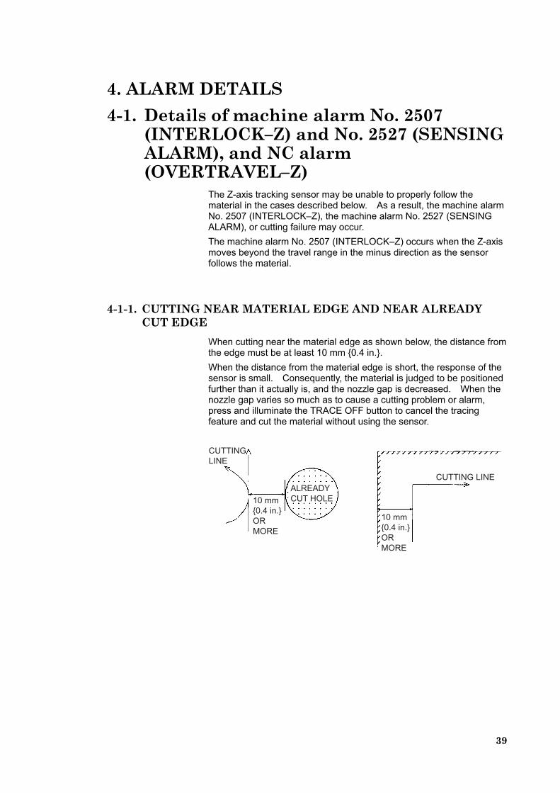
4-1-1. CUTTING NEAR MATERIAL EDGE AND NEAR ALREADY CUT EDGE
When cutting near the material edge as shown below, the distance from the edge must be at least 10 mm {0.4 in.}. When the distance from the material edge is short, the response of the sensor is small. Consequently, the material is judged to be positioned further than it actually is, and the nozzle gap is decreased. When the nozzle gap varies so much as to cause a cutting problem or alarm, press and illuminate the TRACE OFF button to cancel the tracing feature and cut the material without using the sensor.
������� ���
�������
���
� ��
��� ����
��
���
������
��� ���
� ���
��� ����
���
���
40
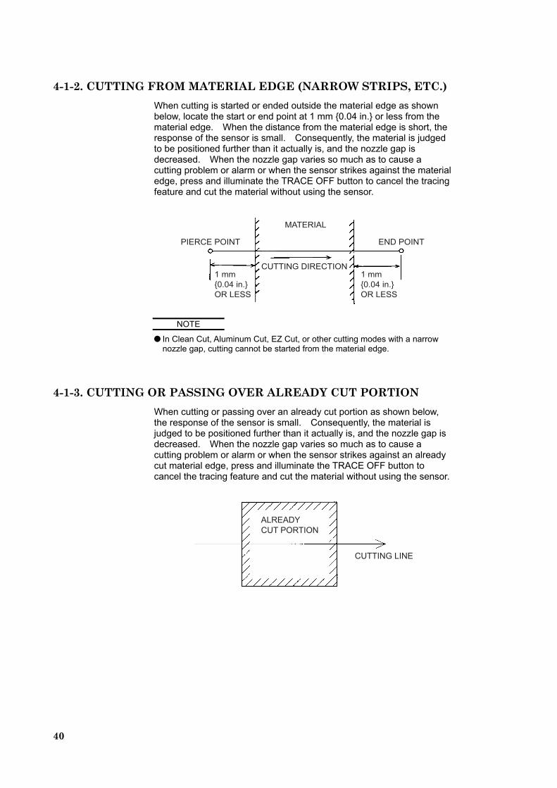
4-1-2. CUTTING FROM MATERIAL EDGE (NARROW STRIPS, ETC.) When cutting is started or ended outside the material edge as shown below, locate the start or end point at 1 mm {0.04 in.} or less from the material edge. When the distance from the material edge is short, the response of the sensor is small. Consequently, the material is judged to be positioned further than it actually is, and the nozzle gap is decreased. When the nozzle gap varies so much as to cause a cutting problem or alarm or when the sensor strikes against the material edge, press and illuminate the TRACE OFF button to cancel the tracing feature and cut the material without using the sensor.
������ ����
���
���� ����
�� ����
��
���� ����
�� ����
�������
����� ��������
��� ����
NOTE
In Clean Cut, Aluminum Cut, EZ Cut, or other cutting modes with a narrow nozzle gap, cutting cannot be started from the material edge.
4-1-3. CUTTING OR PASSING OVER ALREADY CUT PORTION When cutting or passing over an already cut portion as shown below, the response of the sensor is small. Consequently, the material is judged to be positioned further than it actually is, and the nozzle gap is decreased. When the nozzle gap varies so much as to cause a cutting problem or alarm or when the sensor strikes against an already cut material edge, press and illuminate the TRACE OFF button to cancel the tracing feature and cut the material without using the sensor.
CUTTING LINE
ALREADYCUT PORTION
41
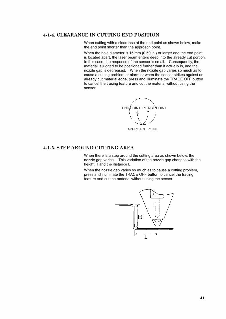
4-1-4. CLEARANCE IN CUTTING END POSITION When cutting with a clearance at the end point as shown below, make the end point shorter than the approach point. When the hole diameter is 15 mm {0.59 in.} or larger and the end point is located apart, the laser beam enters deep into the already cut portion. In this case, the response of the sensor is small. Consequently, the material is judged to be positioned further than it actually is, and the nozzle gap is decreased. When the nozzle gap varies so much as to cause a cutting problem or alarm or when the sensor strikes against an already cut material edge, press and illuminate the TRACE OFF button to cancel the tracing feature and cut the material without using the sensor.
APPROACH POINT
END POINT PIERCE POINT
4-1-5. STEP AROUND CUTTING AREA When there is a step around the cutting area as shown below, the nozzle gap varies. This variation of the nozzle gap changes with the height H and the distance L. When the nozzle gap varies so much as to cause a cutting problem, press and illuminate the TRACE OFF button to cancel the tracing feature and cut the material without using the sensor.
42
4-1-6. OCCURRENCE OF PLASMA DURING CUTTING When plasma occurs during cutting, the electrostatic capacitance-type sensor becomes unstable in its detection function. When a strong flash (of bluish white light) occurs to cause the Z-axis to move unstably, produce an alarm, or touch the material, press and illuminate the TRACE OFF button to cancel the tracing feature and cut the material without using the sensor.
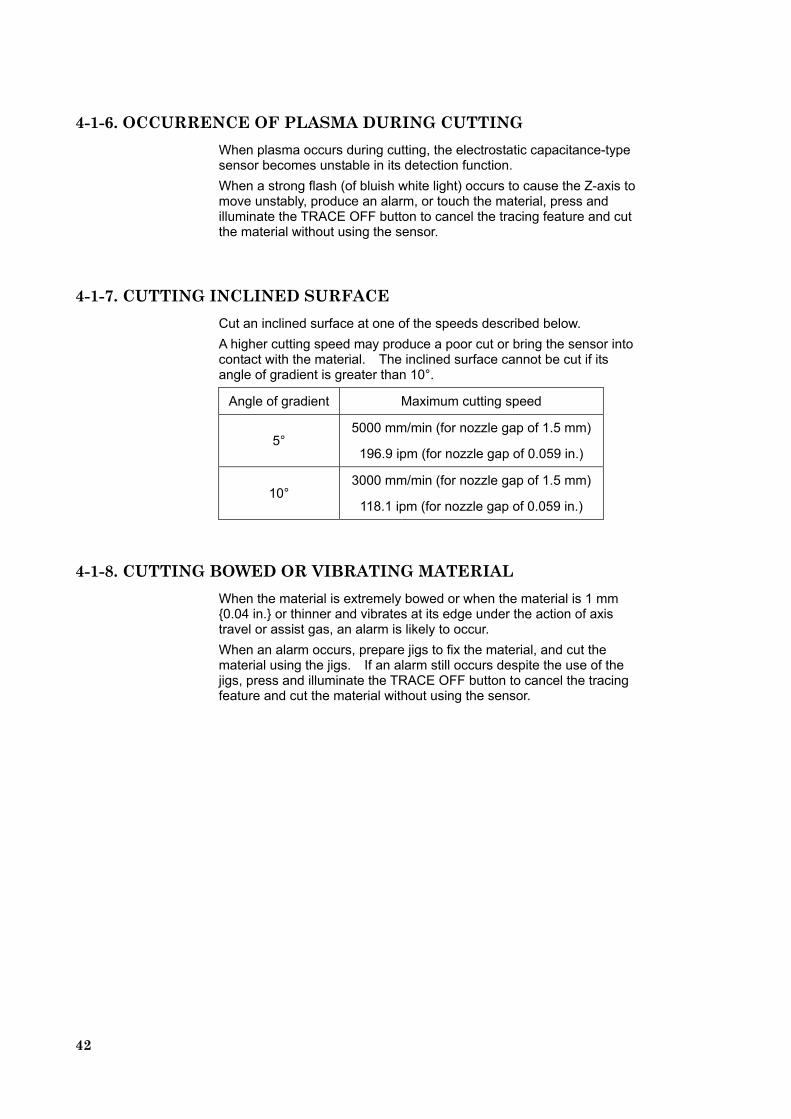
4-1-7. CUTTING INCLINED SURFACE Cut an inclined surface at one of the speeds described below. A higher cutting speed may produce a poor cut or bring the sensor into contact with the material. The inclined surface cannot be cut if its angle of gradient is greater than 10°.
Angle of gradient Maximum cutting speed
5° 5000 mm/min (for nozzle gap of 1.5 mm)
196.9 ipm (for nozzle gap of 0.059 in.)
10° 3000 mm/min (for nozzle gap of 1.5 mm)
118.1 ipm (for nozzle gap of 0.059 in.)
4-1-8. CUTTING BOWED OR VIBRATING MATERIAL When the material is extremely bowed or when the material is 1 mm {0.04 in.} or thinner and vibrates at its edge under the action of axis travel or assist gas, an alarm is likely to occur. When an alarm occurs, prepare jigs to fix the material, and cut the material using the jigs. If an alarm still occurs despite the use of the jigs, press and illuminate the TRACE OFF button to cancel the tracing feature and cut the material without using the sensor.


200, Ishida, Isehara, Kanagawa, JAPAN
Printed on recycled paper.