laser driven plasma wakefield: progation effects -...
TRANSCRIPT

1
B. Cros, JUAS 2012 1
Laser driven plasma wakefield: progation effects
Laser driven plasma wakefield: progation effects
Brigitte CrosLaboratoire de Physique des Gaz et des Plasmas
CNRS-Université Paris Sud, Orsay, France
Propagation effects play an important role in LPA
Propagation effects play an important role in LPA
The ultra-high intensity required fo laser wakefield isusually achieved inside a small volume
Acceleration of electrons to ultra-high energiesrequires to maintain a high acceleration gradient over a long distance
Ultra-intense laser beams interact with matter and give rise to non linear effects, which usually grow withpropagation distance
B. Cros, CAS November 2014 2

2
OutlineOutline
B. Cros, CAS November 2014 3
Laser plasma acceleration characteristics (reminder)Description of laser and plasma wave
Electron acceleration parameters
Optimization of interaction length to achieve the maximum energy gain
Laser guiding by grazing incidence reflectionGuiding properties
Plasma wave excitation
Optical guiding in plasmas
Longitudinal density gradient
Staging
Laser propagation in vacuumLaser propagation in vacuum
Ultra High Intensity, larger than ~1018 W/cm²
The beam has to be focused w0
Typical volume small w0²ZR ~10µmx10µmx300µm
B. Cros, CAS November 2014 4

3
Electric field amplitude described with Gaussian distributions
Electric field amplitude described with Gaussian distributions
Transverse waist
Rayleigh length
B. Cros, CAS November 2014 5
Energy, waist, and duration can be measured experimentally
Energy, waist, and duration can be measured experimentally
Laser power
Intensity
Peak intensity
Laser strength parameter a
a ~ eA/mc² (normalized laser vector potential)
Peak value a0 ~ 8.5x10⁻¹⁰ [µm] I01/2[Wcm-2]
Quasilinear regime a0 ~ 1 , or weakly relativistic regime
B. Cros, CAS November 2014 6

4
Example of energy distribution in the focal plane
Example of energy distribution in the focal plane
UHI beam with adaptative correction
Grey area = 84 % of energy in the focal plane
Good beam quality in the focal plane
B. Cros, CAS November 2014 7Ju et al., Phys. Plasmas 20, 083106 (2013)
The plasma is used as a transformerThe plasma is used as a transformer
Single electrons wiggle in the transverse laser field
In a plasma, the action of the ponderomotive force leads to a plasma wave (time average)
B. Cros, CAS November 2014 8
k0
E
B
kp
Ep
For IL~1018W/cm², |E| ~ 1012V/m: why don’t we use the laser field directly?

5
B. Cros, JUAS 2012 9
Longitudinal electric field associated to a plasma wave
Longitudinal electric field associated to a plasma wave
Accelerating fields > 100 GV/m
ne = Zni
ne +dne
ESpace charge fieldPlasma wavelength
p[µm] ~33 (ne[1018cm-3])1/2
v
x
E
p
Relativistic wave:
phase velocity of the order of the laser group velocity
B. Cros, JUAS 2012 10
Dephasing length for accelerated electrons Dephasing length for accelerated electrons
Energy gain
W = e Ep La
= p / 0
Ep t1 t2 t3v~c
v~cLa < Ldeph = p 2
ne 1017cm-3 1019cm-3
100 10
La 1 m 1 mm
Wmax 20 GeV 200 MeV
W ~ ne-1
Ep ~ ne1/2
La ~ ne-3/2

6
Linear vs NL regime of LPALinear vs NL regime of LPA
2 main regimes:quasilinear regime
bubble or blowout regime
B. Cros, CAS November 2014 11
a =
Importance of transverse structure to define these regimes
12
Laser wakefield: quasilinear regimeLaser wakefield: quasilinear regime
Ponderomotive force ~gradient of laser energy
Independent control of transverse and longitudinal fields
Accelerating structure sine wave: λp~10-100µm
Accelerating field: 1-100 GV/m
It is necessary to inject electrons produced by an external source

7
13
• Compression and self-focusing of the pulse
• Expulsion of electrons: creation of a bubble (ions)
• Electrons self-injected at the back of the bubble by accelerating and focusing fields
• Injected electrons modify the back of the bubble (beam loading)
•Generation of betatronradiation
Non linear wakefield with self-injectionNon linear wakefield with self-injection
W. Lu PRSTAB, 10, 061301 (2007), A. Pukhov et al, Appl. Phys. B 74, 355 (2002)
3 main mechanisms to control electron acceleration distance3 main mechanisms to control electron acceleration distance
Laser diffraction: typically the Rayleigh length
Pump depletion: length over which half of the laser energy is transferred to the plasma wave
Dephasing length: distance over which electronsoutrun the plasma wave and enter a deceleratingphase
B. Cros, CAS November 2014 14

8
Scaling laws in the different regimes
Scaling laws in the different regimes
B. Cros, CAS November 2014 15
W. Lu PRSTAB, 10, 061301 (2007)
Dephasing length
Laser depletion length
Electron energy gain over Ld
Relativistic factor of plasma wave
16
Energy gain in a laser plasma accelerator
Energy gain in a laser plasma accelerator
ΔW = e Ep L
The length of acceleration is determined by eitherThe Rayleigh length
The dephasing of electrons entering a decelerating phase of the plasma : Ldeph 1/ ne
3/2
The damping of laser energy Lam 1/ (a0² ne3/2)
Optimum length: Ldeph~Lam and a0~1
ΔW 1/ne
To increase energy gain requiresTo lower electron density
To increase interaction length
While maintaining a0~1
9
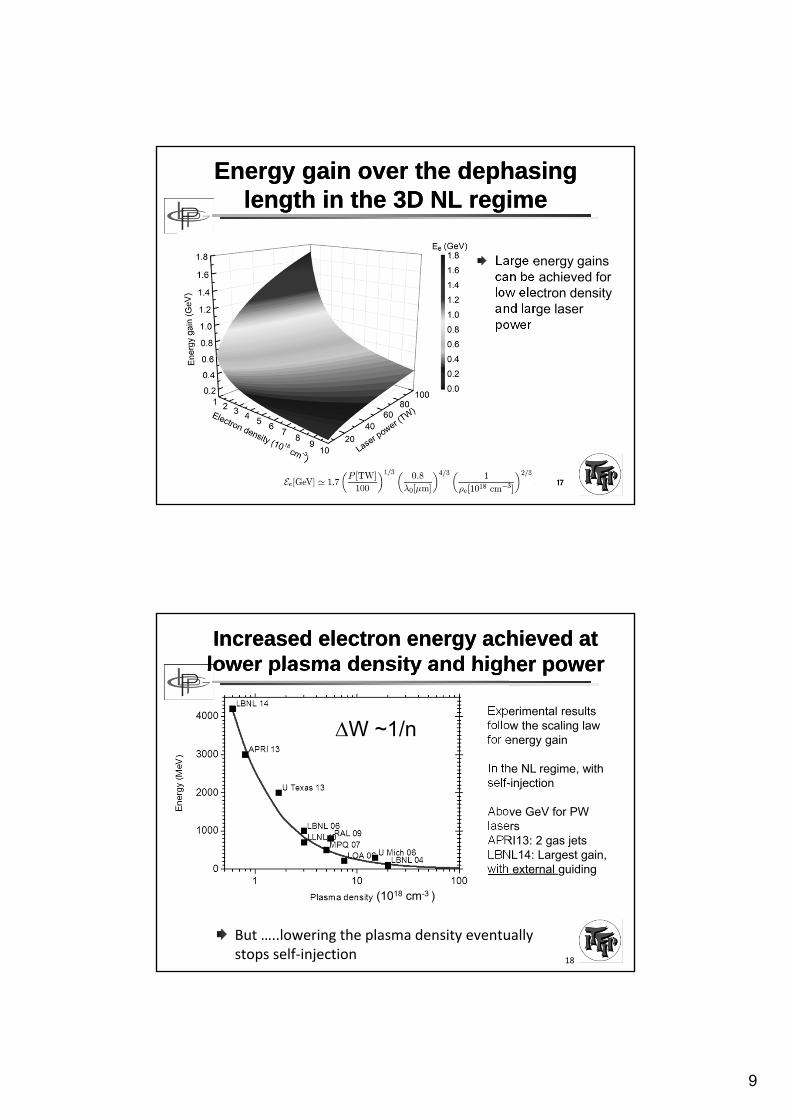
Energy gain over the dephasing length in the 3D NL regime
Energy gain over the dephasing length in the 3D NL regime
Large energy gains can be achieved for low electron density and large laser power
B. Cros, CAS November 2014 17
Increased electron energy achieved atlower plasma density and higher powerIncreased electron energy achieved at
lower plasma density and higher power
But …..lowering the plasma density eventually stops self‐injection 18
Experimental resultsfollow the scaling lawfor energy gain
In the NL regime, withself-injection
Above GeV for PW lasersAPRI13: 2 gas jetsLBNL14: Largest gain, with external guiding
W ~1/n
(1018 cm-3 )

10
OutlineOutline
B. Cros, CAS November 2014 19
Laser plasma acceleration characteristics (reminder)Description of laser and plasma wave
Electron acceleration parameters
Optimization of interaction length to achieve the maximum energy gain
Laser guiding by grazing incidence reflectionGuiding properties in vacuum
Plasma wave excitation
Optical guiding in plasmas
Longitudinal density gradient
Staging
20
Laser guiding to overcome the limitation due to laser diffractionLaser guiding to overcome the
limitation due to laser diffraction
Vacuumor plasma
Glass
Glass
Plasma channel: transverse variation of density yields refractive index profile
A parabolic plasma channel can guide a Gaussian beam with a constant spot size w0 = wm, where wm depends on the curvature of the channel
Plasma channels detailed in S. Hooker talk
Glass capillary tube: Losses are finite, but small if close to grazing incidence
Can couple 98% of Gaussian into EH11 ifw0 = 0.645 Rcap

11
Guiding in capillary tubes at low intensity corresponds to theoryGuiding in capillary tubes at low intensity corresponds to theory
B. Cros, CAS November 2014 21
Rcap/w0=1.47, Lcap=3cm,
Lcap : typically 1-10 cm, scalable to ~1mRcap: from 25µm to 500µm
Veysman et al., JOSAB, 27 1400 (2010)
Eigen mode characteristicsEigen mode characteristics
Solving Maxwell equations with capillary boundary conditions gives hybrid modes solutions (quasi transverse EM modes)
For the mode EH1m, the field amplitude
B. Cros, CAS November 2014 22
B. Cros et al. Phys Rev. E. 65 026405 (2002)

12
Field distribution in the transverse plane for the 3 first modes
Field distribution in the transverse plane for the 3 first modes
For Rcap=50µmB. Cros, CAS November 2014 23
EH11 EH12 EH13
Eigen mode characteristicsEigen mode characteristics
For the mode EH1m, the field amplitude
is multiplied by 1/e over the characteristic damping length
Group velocity:
B. Cros, CAS November 2014 24
Eigen value
Dielectric function of the wall

13
Damping length increases with the cube of capillary radius
Damping length increases with the cube of capillary radius
B. Cros, CAS November 2014 25
Rcap = 35µm
Rcap = 25µm
Ld = 31cm
Ld = 11cm
ZR ~ 0.1cm
Monomode guiding demonstrated experimentally for I ~1016 W/cm²
Dorchies et al., PRL 82, 4655 (1999)
Parameters of the 9 first modes Parameters of the 9 first modes
Mode properties for Rcap = 50µm and laser wavelength 0.8µm
B. Cros, CAS November 2014 26
Eigen valueDamping
lengthGroup velocity
Transverse flux at the wall
Mode number
14
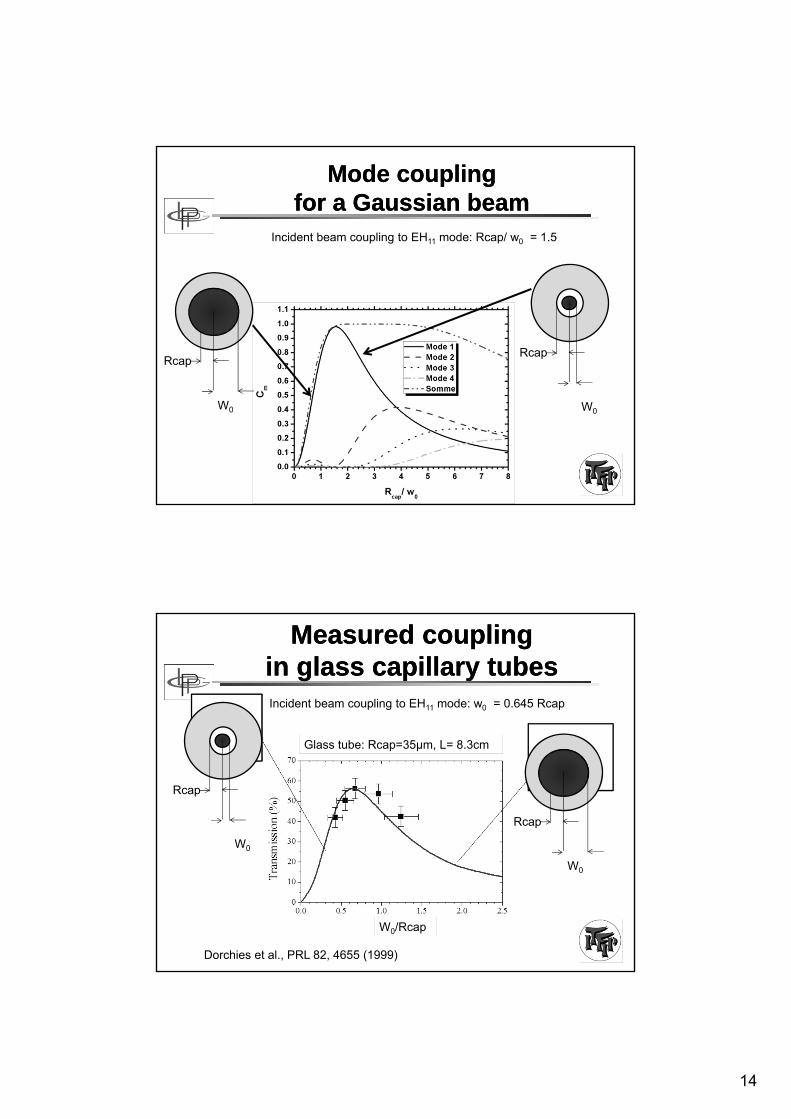
Mode coupling for a Gaussian beam
Mode coupling for a Gaussian beam
Incident beam coupling to EH11 mode: Rcap/ w0 = 1.5
Rcap
W0
Rcap
W0
Measured coupling in glass capillary tubes
Measured coupling in glass capillary tubes
Glass tube: Rcap=35µm, L= 8.3cm
Incident beam coupling to EH11 mode: w0 = 0.645 Rcap
W0/Rcap
Rcap
W0
Rcap
W0
Dorchies et al., PRL 82, 4655 (1999)

15
Monomode output at high intensity (filtering)
Monomode output at high intensity (filtering)
Input:4.2 J @ 0.5µm400 fsw0 = 20 µm
Output:I ~1017 W/cm2
T ~ 30%
Capillary tube: radius 25 µm, L = 12 cm
B. Cros, et al. Physica Scripta T107, 125 (2004).
Monomode EH11 guiding is preferable for LPA
Monomode EH11 guiding is preferable for LPA
B. Cros, CAS November 2014 30
Maximum group velocity
vg c
Minimum damping factor
Ld-1 2.42 2/Rcap3
Smooth gradient of transverse field
E(r) J0 (2.4 r/Rcap)
Single mode excitation

16
OutlineOutline
B. Cros, CAS November 2014 31
Laser plasma acceleration characteristics (reminder)Description of laser and plasma wave
Electron acceleration parameters
Optimization of interaction length to achieve the maximum energy gain
Laser guiding by grazing incidence reflectionGuiding properties in vacuum
Plasma wave excitation
Optical guiding in plasmas
Longitudinal density gradient
Staging
Intense laser guiding in gas filled capillary tube
Intense laser guiding in gas filled capillary tube
B. Cros, CAS November 2014 32
Input focal spotImax 2x10¹⁷W/cm²
Lcap 7 cm, Rcap 50µm
Guiding quality close to monomodefor pressure < 100mbar and a0~1

17
Modification of the laser pulse spectrum during propagationModification of the laser pulse spectrum during propagation
B. Cros, CAS November 2014 3333
AIHT of RAS During the creation of the plasma, the pulse propagates in a rapidly varying medium and its spectrum is modified
Andreev & Chegotov, JETP 101, 56 (2005)
34
Excitation of a plasma wave over a long distance with capillary guidingExcitation of a plasma wave over a
long distance with capillary guiding
Input: Imax = 6.1 1017W/cm2, Rcap=75 µm, L= 71.8 mm,
40 mbar080214_19sp
vacuum080214_02sp
Vacuum40 mbar
Transmission = 0.9
Transmitted spectrum is red-shifted during the excitation of the plasma wave

18
B. Cros, JUAS 2012 35
LPA in the linear regime LPA in the linear regime
Accelerating field in the range (1-10 GV/m) over a long distance (8 cm)
Measured by opticaldiagnostic, excellent agreement with simulation
Capillary tube Rcap ~ 50 µm, L = 8 cm, filled with hydrogenLaser intensity ~ 1017 W/cm2 - 4 TW
Inputlaser
Outputlaser
Andreev et al. New J. Phys. 12 (2010) 045024.
Wojda et al. Phys. Rev. E 80, 066403 (2009)
OutlineOutline
B. Cros, CAS November 2014 36
Laser plasma acceleration characteristics (reminder)Description of laser and plasma wave
Electron acceleration parameters
Optimization of interaction length to achieve the maximum energy gain
Laser guiding by grazing incidence reflectionGuiding properties in vacuum
Plasma wave excitation
Optical guiding in plasmas
Longitudinal density gradient
Staging

19
Optical guiding in plasmasOptical guiding in plasmas
Guiding is achieved when the refractive index decreases radially (similar to optical fibers)
Possible when the plasma density has a minimum on axis
In a plasma channel, for a²<<1:
B. Cros, CAS November 2014 37
Relativistic optical guiding Preformed plasma channel
Self-channeling & self-modulation of laser pulses
Optical guiding in the conditions of resonant wakefield excitationOptical guiding in the conditions of resonant wakefield excitation
B. Cros, CAS November 2014 38
Diffraction is counteracted by a decrease of the refractive index away from the axis
Self-channeling occurs for high enough power and density, P > Pc ~ 17(p/)²
A parabolic density profile is ideal to guide a Gaussian laser pulse (See S. Hooker talk)
Vacuum diffraction
Self-channeling P=Pc
Plasma channel
Evolution of laser spot size as a function of propagation (condition of resonant wakefield)
Sprangle et al. PRL 69, 2200 (1992)

20
Example of guiding in plasma channel for a 40 TW laser
Example of guiding in plasma channel for a 40 TW laser
B. Cros, CAS November 2014 39Leemans et al. Nature Physics 2, 696 (2006) Berkeley+guiding Oxford
3.3 cm long gas filled cap discharge waveguidePlasma density 3.2x1018cm-3Energy transmission 65%
Input Intensity 3 x 10¹⁸ W/cm² Output 1 x 10¹⁸ W/cm²
B. Cros, JUAS 2012 40
Plasma channel extends the acceleration length in the regime of self-injection
Plasma channel extends the acceleration length in the regime of self-injection
Electron bunch with an energy of the order of 1 GeV achieved over a length of 3.3 cm
Longer than dephasing length, the complex pulse evolution has to be taken into account
Leemans et al. Nature Physics 2, 696 (2006) Berkeley+guiding Oxford
L = 33 mm, diam 310µmr spot (1/e²) = 25 µmLaser LBNL 40fs, 1.6J
12 TW, ne = 3.5 1018 cm-3
0.5 GeV, 50pC, dE/E = +/- 5%
40 TW, ne = 4.3 1018 cm-3
1 GeV, 30 pC, dE/E = +/- 2.5%

21
OutlineOutline
B. Cros, CAS November 2014 41
Laser plasma acceleration characteristics (reminder)Description of laser and plasma wave
Electron acceleration parameters
Optimization of interaction length to achieve the maximum energy gain
Laser guiding by grazing incidence reflectionGuiding properties in vacuum
Plasma wave excitation
Optical guiding in plasmas
Longitudinal density gradient
Staging
Density tailoring to overcome dephasing
Density tailoring to overcome dephasing
B. Cros, CAS November 2014 42
Rittershofer et al. PoP 17,063104 ( 2010)
Normalized plasma frequency and channel radius as a function of distance for phase locking the accelerating force
22
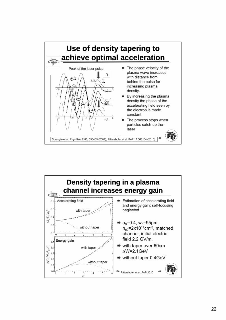
Use of density tapering to achieve optimal acceleration
Use of density tapering to achieve optimal acceleration
The phase velocity of the plasma wave increaseswith distance frombehind the pulse for increasing plasma density.
By increasing the plasma density the phase of the accelerating field seen by the electron is made constant
The process stops whenparticles catch-up the laser
B. Cros, CAS November 2014 43Sprangle et al. Phys Rev E 63, 056405 (2001); Rittershofer et al. PoP 17 063104 (2010)
n
2n
Peak of the laser pulse
Density tapering in a plasma channel increases energy gainDensity tapering in a plasma
channel increases energy gain
B. Cros, CAS November 2014 44
Estimation of accelerating fieldand energy gain; self-focusingneglected
a0=0.4, w0=95µm, ne0=2x1017cm-3, matchedchannel, initial electricfield 2.2 GV/m.
with taper over 60cm W=2.1GeV
without taper 0.4GeV
Rittershofer et al. PoP 2010
with taper
with taper
without taper
without taper
Accelerating field
Energy gain

23
OutlineOutline
B. Cros, CAS November 2014 45
Laser plasma acceleration characteristics (reminder)Description of laser and plasma wave
Electron acceleration parameters
Optimization of interaction length to achieve the maximum energy gain
Laser guiding by grazing incidence reflectionGuiding properties in vacuum
Plasma wave excitation
Optical guiding in plasmas
Longitudinal density gradient
Staging
What’s next?What’s next?
Staging can be used to provide fresh laser and plasma,.... and a new set of issues
46
W ~1/n
(1018 cm-3 )
Increased electron energy is achieved at lower plasma density and higher power
Lowering the plasma density eventually stops self-injection
Dephasing sets the maximum acceleration length in the quasilinear regime

24
B. Cros, JUAS 2012 47
Laser plasma collider conceptLaser plasma collider concept
Challenges for a multi-stage LPAChallenges for a multi-stage LPA
Improve the performance of laser systems:Beam quality, reliability , stability
Average power (10Hz à 10kHz)
Plasma stages in the quasi linear regime to control transverse and longitudinal fields:
provides control of beam dynamics
electron or positron beams
meter scale plasma sources need to be developped at lowdensity
External injection schemesbeam transport and shaping need to be developped for electron and laser beams
Design through European collaboration

25
The preservation of a high average gradient requires compact laser coupling
The preservation of a high average gradient requires compact laser coupling
The large power (~PW) and large spot (~100µm) require several meters to focus laser beams into plasma stages:
Plasma mirrors are promising schemes for compact coupling
Currently used for temporal contrast improvement
Innovative, high repetition rate schemes are beingdevelopped (metallic tape or liquid jet)
B. Cros, CAS November 2014 49
Plasma creationne>ncreflecting plasma
G. Doumy et al., Phys. Rev. E ,2004
Transparent medium
Plasmas mirrors :ultra –fast optical switchesCourtesy of P. Monot, CEA-Saclay
BV
BC
The pedestal goes throughthe transparent medium
10 eV1 eV
Multiphotonic absorption or tunnel effect + avalanche
BV
BC
26
B. Cros, JUAS 2012 51
SummarySummary
LPA currently produce electron bunches of extremely short duration (<10fs), up to several GeV, achieved by operationat lower densityLaser guiding and increased laser energy should produceelectron bunches in the ~10 GeV range in one stage (ex: BELLA project in the USA or APOLLON 10 PW in France)Staging is the next milestone for the development of LPA
Very active and motivating field of research:involving laser, plasma and accelerator physics, several facilites under development, need for students, researchers and engineers