laser beam divergence utilizing a lateral shearing...
TRANSCRIPT

Laser beam divergence utilizing a lateralshearing interferometer
M. E. Riley and M. A. Gusinow
An analysis of the lateral shearing interferometer is given for laser beams. The results enable a simple de-termination of the local radius of curvature of the wavefront. In addition, the presence of phase distortionin the beam may be ascertained.
Introduction
The wedged, lateral shearing interferometer' is veryuseful for measuring laser-beam wavefront curvatureand for inferring beam divergence. Although shearinginterferometers have been used and analyzed for manyyears, there is no derivation in the literature of theformulas for the evaluation of the wavefront radius ofcurvature.
Bates2 first discussed the principle of the lateralshearing interferometer. Important extensions weremade by Drew3 and by Brown.4 The original applica-tion was to measure aberrations produced by opticalelements. These early, relatively complex, devices weredesigned to maintain a zero optical path difference forthe sheared beams. A significant advance in shearinginterferometry was made by Murty 5 who introduced thesimple wedged (or plane parallel) glass plate with anonzero optical path difference. This instrument mustbe used with nearly monochromatic sources, and it is thesubject of this paper. To date there have been few re-ports of laser beam analysis using the Murty-type in-terferometer. Anthes et al. 6 reported an experimentusing a high-power glass laser in which the beam di-vergence was determined by measuring the fringerotation of the interferogram. Lurie7 reported ananalysis but did not give the formulas necessary for in-terpretation of rotated fringe patterns. His results arealso restricted to near-normal incidence on the shearplate.
A general description of shearing interferometry andapplications may be found in Refs. 8 and 9. Analysisof the interferograms is covered in Refs. 10-14 withemphasis on the testing of optical elements. The pur-
The authors are with Sandia Laboratories, Albuquerque, NewMexico 87115.
Received 14 March 1977.
pose of the present work is to present an analysis of theMurty-type instrument relevant to the determinationof laser beam collimation properties.
AnalysisThe principle of the interferometer involves dividing
the initial laser beam into two components of approxi-mately the same intensity and displacing them laterallywith respect to one another. In that region where thetwo beams overlap, interference results. As described,it is seen that the interferogram compares the originalphasefront relative to itself, displaced by the sheardistance.
Figure 1 shows a side and top view of the interfer-ometer with exemplary ray paths. The wedge angle 3has been greatly exaggerated in this schematic drawing.A left-handed coordinate system (x,y,z) is erected withthe origin at the point of intersection of the incidentprincipal ray and the front surface. The z axis lies onthe reflected ray from the front surface; the x axis liesin the plane of incidence; the y axis is upward (out of theplane of the figure in the top view). The reflected beamfrom the front surface is given by
(1)El = 6(x,y,z) exp[-ikz - i(x,y,z)].
The phase will be taken to be of the form
'(xyz) = k (X2
+ y2 ),2RWz
where R(z) is the local radius of curvature of thephasefront. This form of 4) can arise from the paraxialapproximation to a spherical wavefront. The specificform of the amplitude 6 is immaterial for the analysis.It is assumed to be characterized by a transverse di-mension w(z). Aberrations, if present, would manifestthemselves by the presence of additional, spatially de-pendent terms 12 in Eq. (2).
The path of the second reflected principal ray mustbe calculated. The exact solution is easy to obtain, butonly the limiting form for a very small wedge angle 5 is
October 1977 / Vol. 16, No. 10 / APPLIED OPTICS 2753
(2)

In this coordinate system the second reflected beammay be written
E2 = (x',y',z' + D) exp[-ik(z' + D) - iM(x',y',z' + D)],
where D is the optical pathlength difference. Thesecond reflected beam will contain a small amount ofastigmatism introduced by passage through the plate.15This effect is small as long as D << R(O) and has beenneglected. For small , D is given by
D = 2t(n 2 - sin2 a)1/2 .
- _ Top View
Fig. 1. A schematic representation of a lateral shearing interfer-ometer of the Murty type.
(6)
The reflected beams are taken to be of equal intensity.The interference pattern on a plane at distance z fromthe shear plate is given by El + E2 2. If the variationsin the beam amplitude are small over transverse dis-tances of size s, the interference pattern at z is givenby
sin2 [kz - kz' - kD + 'b(x,y,z) - D(x',y',z' + D)]2
(7)
The coordinate transformation, Eq. (5), allows thepattern to be expressed in terms of the x,y,z system. Itis possible to make reasonable approximations con-cerning the tilt displacements and optical path differ-ence: Oz << s < w(z); Oy << R(z); andD << R(z). w(z)and R (z) are measures of the transverse dimension andradius of curvature of the incident electric field. Theresult is an interference pattern at z = L (the observa-tion plane) described by
sin2 I [kOy -kD + 4'(x,y,L) - 4(x -s,y,L)].2
(8)
In the case of a beam with a rotationally symmetricparabolic phasefront as given by Eq. (2), the argumentof Eq. (8) reduces to
ks k O L (2R(L) 2 R(L) (9)
Fig.. 2. A schematic representation of the interference pattern re-sulting from a lateral shearing interferometer.
necessary. In terms of the plate thickness, angle ofincidence, and index of refraction, one finds the lateralshear distance s and the tilt angle 0:
sin2cas =t -- ,(3)(n -sin2a)1/2
0 = 26(n2 - sin2 a)/ 2 . (4)
These quantities are indicated in Fig. 1 in the standardconfiguration of the device. Another coordinate systemis erected with the z' axis along the second reflectedprincipal ray. It is defined by the transformation
x' = x-A,
(y') (cosO sinO y 1_ 0 (5)
z( -sin0 cosO ( ) o<i (-0C1) (YZ)
where o is independent of x and y. By equating thisto multiples of r, the equations for fringe spacing andangle of rotation of the fringes o are obtained:
d = 0[1 - L/R(L)J
sdtanzp=- ;
XR (L)
sKsmnp = - ~R(XR(L)'
(10)
(11)
(12)
d is the spacing perpendicular to the direction of shear,and K is the spacing normal to the fringes.
Figure 2 illustrates the various quantities for a con-verging beam of negative radius of curvature. From Eq.(4), it is seen that the tilt angle has only a slight depen-dence on the angle of incidence for most plate materials.(The interferometer in this work was made of BK-7glass which has n = 1.515 at 6328 A.) The shear dis-tance is maximum at approximately 490 incidence, anda maximum fringe rotation is produced at this angle. Asingle interferogram supplies a measurement of d or Kand . The shear can be either measured or calculatedfrom Eq. (3). These quantities are used in conjunction
2754 APPLIED OPTICS / Vol. 16, No. 10 / October 1977
Side View
A\ FilmShutter
Lateral -Shear-Plate
He-NeLaser
[] t 3 v)Mirror
Beam ExpandingTelescope - PinholeCombination
Fig. 3. The experimental arrangement used to make the radius-of-curvature measurements.
Fig. 5. The interferogram resulting by allowing the laser beam toimpinge on a spherical mirror (R = 38.74 m). The angle of incidence
at the interferometer was 3 °.
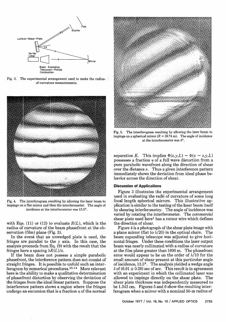
Fig. 4. The interferogram resulting by allowing the laser beam toimpinge on a flat mirror and then the interferometer. The angle of
incidence at the interferometer was 13.5°.
with Eqs. (11) or (12) to evaluate R(L), which is theradius of curvature of the beam phasefront at the ob-servation (film) plane (Fig. 3).
In the event that an unwedged plate is used, thefringes are parallel to the y axis. In this case, theanalysis proceeds from Eq. (9) with the result that thefringes have a spacing XR (L)/s.
If the beam does not possess a simple parabolicphasefront, the interference pattern does not consist ofstraight fringes. It is possible to unfold such an inter-ferogram by numerical procedures. 10-14 More relevanthere is the ability to make a qualitative determinationof phasefront distortion by observing the deviation ofthe fringes from the ideal linear pattern. Suppose theinterference pattern shows a region where the fringesundergo an excursion that is a fraction wi of the normal
separation K. This implies 4)(x,y,L) - 4)(x -- s,y,L)possesses a fraction 11 of a full wave distortion from apure parabolic wavefront along the direction of shearover the distance s. Thus a given interference patternimmediately shows the deviation from ideal phase be-havior across the direction of shear.
Discussion of Applications
Figure 3 illustrates the experimental arrangementused in evaluating the radii of curvature of some longfocal length spherical mirrors. This illustrative ap-plication is similar to the testing of the laser beam itselfby shearing interferometry. The angle of incidence wasvaried by rotating the interferometer. The commercialshear plate used here' has a cursor wire which definesthe direction of shear.
Figure 4 is a photograph of the shear plate image witha plane mirror (flat to X/20) in the optical chain. Thebeam expanding telescope was adjusted to give hori-zontal fringes. Under these conditions the laser outputbeam was nearly collimated with a radius of curvatureat the film plane greater than 1600 m. The phasefronterror would appear to be on the order of X/10 for thesmall amount of shear present at this particular angleof incidence, 13.5°. The analysis yielded a wedge angle6 of (6.91 0.28) sec of arc. This result is in agreementwith an experiment in which the collimated laser wasallowed to impinge directly on the shear plate. Theshear plate thickness was independently measured tobe 1.343 cm. Figures 5 and 6 show the resulting inter-ferogram when a mirror with a nominal 50-m radius of
October 1977 / Vol. 16, No. 10 / APPLIED OPTICS 2755

Fig. 6. The interferogram resulting by allowing the laser beam to impinge on a spherical mirror (R = 38.74 m). The angle of incidence at theinterferometer was 3 0.
curvature was inserted in place of the flat mirror. Theradius of curvature of the laser beam obtained from theinterferogram refers to the curvature at the film plane.An analysis of Figs. 5 and 6, taken at incident angle of30 and 300, respectively, yielded a radius of curvatureof 1719 cm and 1764 cm, respectively, at the film plane.When extrapolated back to the spherical mirror theseradii of curvature became 19.40 m and 19.35 m. Theradius of curvature of the beam at the mirror locationis one-half of the radius of curvature of the mirror sur-face. Hence, the average of these two measurementsyields a radius of curvature of the mirror surface of 38.74m which is to be compared to the manufacturer's claimof 50 m. A similar experiment used a spherical mirrorstated to have a radius of curvature of 10 m; in this caseit was found to have a radius of curvature of (9.97 +0.02) m.
While the experimental work reported here dealt withmeasuring the radius of curvature of spherical mirrors,the intent is to emphasize the use of the lateral shearinginterferometer for the measurement of the radius ofcurvature of a laser beam. From this latter measure-ment, it is possible to infer the divergence (or conver-gence) of a laser at any point along its direction ofpropagation.
The authors acknowledge useful discussions withJohn P. Anthes.
This work was supported by the U.S. Energy Re-search and Development Administration.
References1. Lateral shearing interferometers of the type discussed in this work
are available commercially. Ours was obtained from ContinentalOptical Corporation, Hauppauge, N.Y.
2. W. J. Bates, Proc. Phys. Soc., 59, 940 (1947).3. R. L. Drew, Proc. Phys. Soc. (London) Sect. B 64, 1005 (1951).4. D. Brown, Proc. Phys. Soc. (London) Sect. B 67, 232 (1954).5. M. V. R. K. Murty, Appl. Opt. 3, 531 (1964).6. J. P. Anthes, J. W. Lavasek, and M. A. Palmer, "A Picosecond and
Nanosecond Nd Glass High Power Laser Amplifier System,"Report SAND76-0432, Sandia Laboratories, Albuquerque, N.M.87115.
7. M. Lurie, Opt. Eng. 15, 68 (1976).8. W. H. Steel, Interferometry (Cambridge U. P., London, 1967).9. 0. Bryngdahl, "Applications of Shearing Interferometry," in
Progress in Optics, E. Wolf, Ed. (North Holland, Amsterdam,1965).
10. J. B. Saunders, J. Res. Nat. Bur. Stand., Sect. B 65, 239 (1961).11. D. Dutton, A. Cornejo, and M. Latta, Appl. Opt. 7, 125 (1968).12. D. Nyyssonen and J. M. Jerke, Appl. Opt. 12, 2061 (1973).13. M. P. Rimmer, Appl. Opt. 13, 623 (1974).14. M. P. Rimmer and J. C. Wyant, Appl. Opt. 14, 142 (1975).15. J. A. Arnaud and H. Kogelnik, Appl. Opt. 8, 1687 (1969).
2756 APPLIED OPTICS / Vol. 16, No. 10 / October 1977