lase-a-lign ex page1 - john crane group€¦ · lase-a-lign ex shaft alignment system – an...
TRANSCRIPT

LASE-A-LIGN™ EXSHAFT ALIGNMENT SYSTEM
Installation, Operation & Maintenance Instructions
PAGE1
Table of Contents
LASE-A-LIGN™ EX Shaft Alignment System intrinsically safe package 89658201 (ALI 12.000 EX) ...................... 4
Safety notes .............................................................................................................................................................. 6
Operating information ................................................................................................................................................. 9
LASE-A-LIGN EX Shaft Alignment System – an overview .................................................................................... 11
Description ................................................................................................................................................................ 11
Power supply ............................................................................................................................................................. 11
Transducer ................................................................................................................................................................. 12
Reflector .................................................................................................................................................................... 13
Mini compact chain-type bracket ............................................................................................................................... 14
Interface for data exchange with a PC/printer, transducer and power supply .............................................................. 15
Configuration and data management ................................................................................................................... 16
Shortcut numbers ...................................................................................................................................................... 16
Configuration ............................................................................................................................................................ 16
Getting started ........................................................................................................................................................ 24
Set up LASE-A-LIGN EX Shaft Alignment System ........................................................................................................ 24
Enter dimensions ....................................................................................................................................................... 24
Measure .................................................................................................................................................................... 24
Results ....................................................................................................................................................................... 25
Horizontal machine alignment .............................................................................................................................. 27
1. Preparing for the alignment procedure .................................................................................................................. 27
2. Check for soft foot ................................................................................................................................................ 27
3. Mount the brackets ............................................................................................................................................... 27
4. Mount the EX Bluetooth Module,Transducer and Reflector..................................................................................... 28
5. Switch LASE-A-LIGN EX Shaft Alignment System on and start application .............................................................. 30
6. Switch the EX Bluetooth Module on ....................................................................................................................... 30
7.1 Enter machine dimensions ................................................................................................................................... 32
7.2 Machine set-up .................................................................................................................................................... 34
7.3 Laser beam adjustment ........................................................................................................................................ 42
8. Take measurements ............................................................................................................................................... 45
9. Results ................................................................................................................................................................... 46
10. Align machine ...................................................................................................................................................... 49
11. Saving data and printing ...................................................................................................................................... 54
LASE-A-LIGN™ EXSHAFT ALIGNMENT SYSTEM
Installation, Operation & Maintenance Instructions
PAGE2

Quick check measurement ..................................................................................................................................... 58
Soft foot .................................................................................................................................................................... 59
Checking and correcting soft foot conditions ............................................................................................................. 59
Checking pipe strain .................................................................................................................................................. 63
Alignment options ................................................................................................................................................. 66
Measurement modes ................................................................................................................................................. 66
Updating the LASE-A-LIGN EX Shaft Alignment System firmware ..................................................................... 72
Updating LASE-A-LIGN EX Shaft Alignment System to a newer version ...................................................................... 72
Transducer firmware update ....................................................................................................................................... 75
Special alignment applications .............................................................................................................................. 78
Machine train alignment ............................................................................................................................................ 78
Vertical machine alignment ........................................................................................................................................ 84
Set-up ........................................................................................................................................................................ 84
Appendix ................................................................................................................................................................. 91
Suggested shaft alignment tolerances ........................................................................................................................ 91
LASE-A-LIGN EX Shaft Alignment System technical data ............................................................................................. 92
Attachments .............................................................................................................................................................. 94
LASE-A-LIGN™ EXSHAFT ALIGNMENT SYSTEM
Installation, Operation & Maintenance Instructions
PAGE3
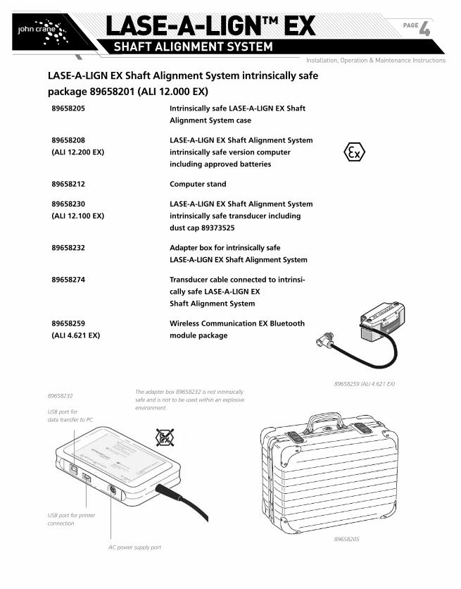
LASE-A-LIGN EX Shaft Alignment System intrinsically safe
package 89658201 (ALI 12.000 EX)
89658205 Intrinsically safe LASE-A-LIGN EX Shaft
Alignment System case
89658208
(ALI 12.200 EX)
LASE-A-LIGN EX Shaft Alignment System
intrinsically safe version computer
including approved batteries
89658212 Computer stand
89658230
(ALI 12.100 EX)
LASE-A-LIGN EX Shaft Alignment System
intrinsically safe transducer including
dust cap 89373525
89658232 Adapter box for intrinsically safe
LASE-A-LIGN EX Shaft Alignment System
89658274 Transducer cable connected to intrinsi-
cally safe LASE-A-LIGN EX
Shaft Alignment System
89658259
(ALI 4.621 EX)
Wireless Communication EX Bluetooth
module package
89658232The adapter box 89658232 is not intrinsically
safe and is not to be used within an explosive
environment. USB port for
data transfer to PC
USB port for printer
connection
AC power supply port
89658205
89658259 (ALI 4.621 EX)
e
LASE-A-LIGN™ EXSHAFT ALIGNMENT SYSTEM
Installation, Operation & Maintenance Instructions
PAGE4
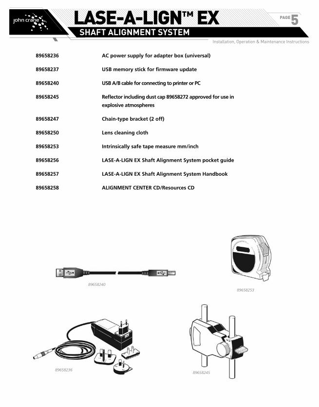
89658236 AC power supply for adapter box (universal)
89658237 USB memory stick for firmware update
89658240 USB A/B cable for connecting to printer or PC
89658245 Reflector including dust cap 89658272 approved for use in
explosive atmospheres
89658247 Chain-type bracket (2 off)
89658250 Lens cleaning cloth
89658253 Intrinsically safe tape measure mm/inch
89658256 LASE-A-LIGN EX Shaft Alignment System pocket guide
89658257 LASE-A-LIGN EX Shaft Alignment System Handbook
89658258 ALIGNMENT CENTER CD/Resources CD
89658240
8965823689658245
89658253
LASE-A-LIGN™ EXSHAFT ALIGNMENT SYSTEM
Installation, Operation & Maintenance Instructions
PAGE5
Safety notes
LASE-A-LIGN EX Shaft Alignment System is to be used
in industrial environments only for shaft alignment.
Care must be taken to ensure that the instrument is not
subjected to mechanical knocks. LASE-A-LIGN EX Shaft
Alignment System must be operated only by properly
trained personnel. No liability will be assumed when
components or operating procedures as described
in this manual are altered without permission of the
manufacturer.
Symbols used in this handbook
The following symbols are used in this manual in order
to draw the reader’s attention to especially important
text, such as that regarding possible sources of danger
or useful operating tips.
NOTE: This denotes general information and tips
regarding operation of LASE-A-LIGN EX
Shaft Alignment System.
This symbol denotes information which
must be followed in order to avoid damage
to equipment.
This symbol denotes information which
must be followed in order to avoid person-
al injury.
Numbers indicate the corresponding operating
step described in these instructions and must be
performed exactly.
CE compliance and electromagnetic compatibility
The intrinsically safe LASE-A-LIGN EX Shaft Alignment
System system 89658201 (ALI 12.000 EX) fulfills the
EC Guidelines for electric devices and those relating
to electromagnetic compatibility as indicated in their
respective conformity certificates which are attached in
the appendix. The certificates can also be downloaded
from the John Crane website.
IP classification
LASE-A-LIGN EX Shaft Alignment System is dust-tight
and protected against water jets (IP65). The transducer
and reflector comply with code IP67 (dust-tight and
protected against immersion).
Notes for intrinsically safe models
In addition to the general notes described previously, the
following notes must strictly be observed when working
in explosive atmospheres.
� When equipment to be aligned is located in
an explosive environment, the intrinsically
safe LASE-A-LIGN EX Shaft Alignment System
computer 89658208 (ALI 12.200 EX) and
the intrinsically safe LASE-A-LIGN EX Shaft
Alignment System transducer 89658230 (ALI
12.100 EX) must be used.
� Batteries must be changed only outside the
explosive area! Note that only alkali-manganese
batteries can be used in explosive atmospheres.
With the LASE-A-LIGN EX Shaft Alignment
System version, use only 1.5V AA MN 1500
batteries from Duracell.
� The LASE-A-LIGN EX Shaft Alignment System
case 89658205 may be taken into the
hazardous area provided all the hints outlined
in this section are adhered to. The final decision
rests with the plant’s safety officer.
� The circuit parameters meet the intrinsic safety
requirements Ex ib IIC.
� The maximum cable length between the
LASE-A-LIGN EX Shaft Alignment System
computer socket and the transducer must not
exceed 5M.
� The interfaces for USB host and device, and the
12 V supply are not certified for use in explosive
environments and therefore its use must take
place outside the hazardous zone, and must be
connected via the adapter box 89658232.
e
a
s
s
LASE-A-LIGN™ EXSHAFT ALIGNMENT SYSTEM
Installation, Operation & Maintenance Instructions
PAGE6

� The adapter box 89658232 is not intrinsical-
ly safe and must therefore be used outside
explosive atmospheres.
� For wireless communication within explosive
environments only the optional intrinsically
safe EX Bluetooth module 89658259 (ALI
4.621 EX) must be used. And this must be
only be connected to the intrinsically safe
LASE-A-LIGN EX Shaft Alignment System
transducer 89658230 (ALI 12.100 EX) .
Attention must be paid to safety notes for the
intrinsically safe EX Bluetooth module outlined
in the next section.
� Devices that rely on the power supply to the
USB host for initiation (for example the USB
memory sticks) must only be connected to the
adapter box outside the explosive area.
� The intrinsically safe LASE-A-LIGN EX Shaft
Alignment System computer may be powered
using the AC power supply 89658236 as
long as the power supply is only used outside
the hazardous area, and is connected via the
adapter box 89658232.
� The installation and operation of the intrin-
sically safe LASE-A-LIGN EX Shaft Alignment
System must be in accordance with the
European regulations (EN 60079-10:2003
ff) and equipment safety law as well as the
general recognized rules of the technology
and this operating manual.
� The most current regulations regarding
servicing, maintenance and testing, as they
appear in EN 60079-14 and EN 60079-17
must be observed. The rules of the manufac-
turer as they appear in this manual must also
be observed.
� The EC type examination certificates (ATEX)
and the IECEx certificates of conformity are
attached in the appendix.
Safety notes for intrinsically safe EX Bluetooth
module
� The intrinsically safe EX Bluetooth module
89658259 (ALI 4.621 EX) must only be
connected with the intrinsically safe sensor
89658230 (ALI 12.100 EX) TÜV 07 ATEX
554148
� Only use 1.5 V AA MN 1500 batteries from
Duracell.
� Each individual battery is intrinsically safe.
Batteries can be changed within the explosive
area. When handling batteries with the
explosive area, necessary precaution must
be taken to avoid short-circuiting the battery
terminals.
� The intrinsically safe EX Bluetooth module
does not require maintenance.
� The circuit parameters meet the intrinsic safety
requirements Ex ib IIC.
� The maximum cable length between the
intrinsically safe EX Bluetooth module and the
sensor not exceed 1 m.
� The installation and operation of the intrin-
sically safe LASE-A-LIGN EX Shaft Alignment
System system must be in accordance with the
European regulations (EN 60079-10-1:2009
ff) and equipment safety law as well as the
general recognized rules of the technology
and the operating manual.
� The most current regulations regarding
servicing, maintenance and testing, as they
appear in ElexV § 13,EN 60079-14 and EN
60079-17 must be observed. The rules of the
manufacturer as they appear in this manual
must also be observed.
e
e
s
s
o
LASE-A-LIGN™ EXSHAFT ALIGNMENT SYSTEM
Installation, Operation & Maintenance Instructions
PAGE7
Notes on usage of the intrinsically safe
LASE-A-LIGN EX Shaft Alignment System case
89658205 within explosive environments
� All components stored under the lockable
compartment must never be used in explosive
environments.
� The lockable compartment MUST remain
closed when inside an explosive environment.
� Spare batteries must be transported only in
the allocated positions inside the lockable
compartment.
NOTE: The following information is meant for the
safety officer to determine the explosion hazard of the
intrinsically safe carrying case.
According to Chapter 1 Article 1 of the ATEX Directive
94/9/EC, the carrying case is not classified as a “device”
and is therefore not governed by this directive.
In determining the explosion hazards that can arise from
the case and its contents use is made of regulation EN
13463-1 (“Non-electrical equipment for use in poten-
tially explosive atmospheres”).
� The aluminum case has a maximum magnesium
content of 3.6% and is therefore permissible for
Group II, Category 2 devices.
� The lower insert foam is made of an electrically
conductive polyolefin with a resistance of 4 kΩ and
therefore cannot suffer from electrostatic charging.
� The upper noppen foam is made of an electrically
conductive polyurethane with a resistance of 10 kΩ.
� According to the CENELEC report R044-001, the
straps holding the upper noppen foam have a width
of 1.5 cm and therefore harmless for Group IIC.
� All metallic components intended for use in
explosive environments and transported using the
intrinsically safe carrying case have a magnesium
content < 7.5% and a coating thickness < 0.2 mm.
� The tape measure housing is made of plastic that is
chrome-plated on both the outside and inside and
therefore has an electrical connection to the metallic
tape. The coating thickness of the tape is < 0.2 mm.
� All components stored under the lockable
compartment and are not intended for use in
explosive atmospheres do not possess internal power
supplies and are appropriately held in place.
� Through the use of individual slots, the spare
batteries adequately isolated and held in position.
� Made out of the same material, the reflector
housing is smaller than the sensor housing and
therefore cannot suffer from electrostatic charging.
� The reflector dust cap has an opening which is
< 20 cm2.
Laser safety
The LASE-A-LIGN EX Shaft Alignment System uses
a class II laser beam. Class II lasers comply with the
requirements outlined in the USA’s FDA specification 21
CFR Ch. 1, Parts 1040.10 and 1040.11 as well as the
ANSI standard. It also fulfills British standard BS 4803
(Part 1 to Part 3) and European Industrial Standard
IEC 825. The class II laser operates at a wavelength of
675 nm, with a maximum pulse duration of 128 µs,
maximum radiant power of 0.8 mW and maximum
radiant energy per pulse of 0.1 µJ. No maintenance is
necessary to keep this product in compliance with the
specifications referred to.
� Do not look directly into the laser beam at any
time. (Since FDA specifications allow maximum
exposure of 0.25 seconds, the natural
blink reaction of the human eye is normally
sufficient to avert any danger, provided that
no optical instruments other than ordinary eye
glasses/contact lenses are used. But as natural
blink reaction may fail to occur, care should be
taken to avoid staring into the beam.)
� Do not insert any optical devices into the
beam path.
� The red LED on the front of the transducer
illuminates whenever the laser beam is
emitted.
LASE-A-LIGN™ EXSHAFT ALIGNMENT SYSTEM
IInstallation, Operation & Maintenance Instructions
PAGE8
Operating information
Temperature range
LASE-A-LIGN EX Shaft Alignment System and its related
system components must be used at temperatures
between 0° and 40° C (32° to 104° F). Outside of this
range, the specified accuracy may not be maintained.
Store LASE-A-LIGN EX Shaft Alignment System and its
related components at temperatures between -20° C
and 60° C (-4° F to 140° F).
Temperature effects and fluctuations
Powerful heat sources or steam located near the laser
beam could influence the accuracy of measurements as
a result of beam deflection. In practice, however, this
effect occurs seldom at distances up to 1 m. If in doubt,
the effect can be eliminated by shielding the system
from the heat/steam source during measurement and
adjustment.
As with all precision optical measurement devices,
sudden fluctuations in temperatures (e.g. resulting from
sunlight), could result in erroneous measurements.
NOTE: Allow adequate time for LASE-A-LIGN
EX Shaft Alignment System and its related com-
ponents to reach the ambient temperature.
Incident light
Avoid exposing LASE-A-LIGN EX Shaft Alignment
System to strong, hot light such as direct sunlight.
Dust and water seals
LASE-A-LIGN EX Shaft Alignment System is water and
contamination resistant to specification IP65; the trans-
ducer and reflector are resistant to specification IP67.
This specification requires that each component be
able to withstand a water jet spray from any direction
(the components are NOT guaranteed to withstand a
full submersion). Note, as with most water-resistant
products, the resistance must be periodically checked
and re-sealed if necessary. This can be carried out during
service and recalibration of the system which should be
carried out every two years.
Interface connection
LASE-A-LIGN EX Shaft Alignment System is fitted with a
single interface for data exchange with a PC/printer, the
transducer as well as mains supply.
Note regarding data storage
With any data processing software, data may be
lost or altered under certain circumstances. John
Crane strongly recommends that you keep a back-
up or printed records of all important data.
John Crane assumes no responsibility for data lost
or altered as a result of improper use, repairs, de-
fects, battery replacement/failures or any other
cause.
John Crane assumes no responsibility, directly or
indirectly, for financial losses or claims from third
parties resulting from the use of this product and
any of its functions, such as loss or alteration of
stored data.
Any waste electrical and electronic parts of LASE-A-
LIGN EX Shaft Alignment System including memory
sticks must be disposed off in accordance with the
WEEE (Waste Electrical and Electronic Equipment)
Directive. Such parts must be taken to the nearest
collection facility.
m
LASE-A-LIGN™ EXSHAFT ALIGNMENT SYSTEM
Installation, Operation & Maintenance Instructions
PAGE9
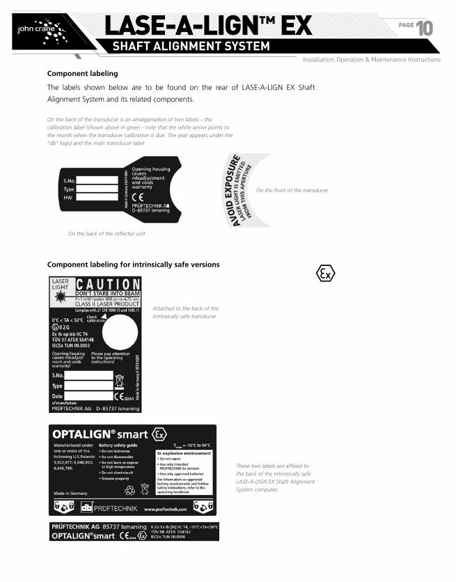
Component labeling
The labels shown below are to be found on the rear of LASE-A-LIGN EX Shaft
Alignment System and its related components.
Component labeling for intrinsically safe versions
On the front of the transducer
On the back of the reflector unit
On the back of the transducer is an amalgamation of two labels – the
calibration label (shown above in green - note that the white arrow points to
the month when the transducer calibration is due. The year appears under the
“db” logo) and the main transducer label.
These two labels are affixed to
the back of the intrinsically safe
LASE-A-LIGN EX Shaft Alignment
System computer.
Attached to the back of the
intrinsically safe transducer
e
LASE-A-LIGN™ EXSHAFT ALIGNMENT SYSTEM
Installation, Operation & Maintenance Instructions
PAGE10

LASE-A-LIGN EX Shaft Alignment System – an overviewDescriptionThe LASE-A-LIGN EX Shaft Alignment System
keyboard at a glanceLASE-A-LIGN EX Shaft Alignment System possesses 3
function keys.
��d The ‘Dimensions’ key is used to initiate entry of
machine dimensions.
��m The ‘Measurement’ key is used to start the
measurement process.
��k The ‘Result’ key is used to call alignment results
into the display.
��ß The ‘Up’ key is used to confirm entered values,
and as a back/return key, taking user to previously
selected screen.
��c The ‘Clr’ (Clear) key is used to delete
information entered inadvertently.
��q The ‘Menu’ key offers a choice of procedures
for setting up the computer and proceeding with
different alignment situations.
��hifg The navigation keys are used to
navigate through the program steps.
��e The ‘On/Off/Enter’ key is used to perform
the dual function of switching on LASE-A-LIGN
EX Shaft Alignment System, confirming entered
values and accessing any selected item. To switch
LASE-A-LIGN EX Shaft Alignment System on, press
the ‘On/Off/Enter’
��1 The data entry keys are used to enter relevant
machine data.
Power supplyBatteries for intrinsically safe version
The intrinsically safe version of LASE-A-LIGN EX Shaft
Alignment System 89658208 (ALI 12.200 EX) (with all
electrical components also suffixed by “EX”), requires
special attention with regard to batteries.
Only alkali-manganese batteries of the type listed
below is to be used with the intrinsically safe com-
puter:
› 1.5 V “AA” MN 1500 from Duracell
Otherwise, intrinsic safety may be compromised.
Be sure to remove the LASE-A-LIGN EX Shaft Align-
ment System computer from the explosive environ-
ment before changing batteries.
DO NOT USE lithium batteries or nickel-cadmium
rechargeable batteries in explosive environments.
The battery compartment of the intrinsically safe LASE-
A-LIGN EX Shaft Alignment System computer is to be
opened with use of a 3 mm allen key.
Used batteries should be disposed of in an environ-
mentally responsible manner in accordance with
applicable regulations!
If LASE-A-LIGN EX Shaft Alignment System com-
puter is not in use for extended periods of time, a
month or more, the batteries should be removed
from the unit.
1. Alignment condition LEDs
2. USB port / Transducer socket
3. Function keys
4. Up / Clear / Menu keys
5. Navigation keys
6. On/Off/Enter keys
7. Data entry keys
8. Wireless communication
indicator LED
9. Battery status LED
e
m
s
a
LASE-A-LIGN™ EXSHAFT ALIGNMENT SYSTEM
Installation, Operation & Maintenance Instructions
PAGE11

Transducer 89658230 (ALI 12.100 EX)
The transducer contains a laser diode which emits a
beam of red light (wavelength 675 nm). The beam is
visible at the point it strikes a surface. It is emitted with
a diameter of approx 5 mm (3/16”). Also located in the
same housing is a beam detector which measures the
exact position of the laser beam as the shafts are rotated.
This component is a biaxial, analog, photoelectric semi-
conductor position detector with a resolution of 1 µm.
The transducer also contains an electronic inclinometer
with resolution better than 1° for measurement of the
shaft rotation angle.
The transducer has two indicator LEDs on its front side,
one green for indicating beam adjustment, and the other
red when the laser is on.
The transducer is IP67 protected to resist water spray
and dust. The internal optics and electronics are sealed
to prevent any possible contamination. The transducer
lens, however, must be kept clean. Use the lens cleaning
cloth 89658250 or a fine dusting brush such as that
normally used to clean other optical devices. Keep the
dust cap on when not in use.
Avoid polishing the lens too vigorously to prevent
irreparable damage to its anti-reflective coating.
Under no circumstances may the six smaller hous-
ing screws be removed, as that would result in loss
of calibration and would void all warranty cover-
age.
NOTE: The calibration accuracy of the transducer
should be checked every two years as indicated by
the colored label located on the back of the receiv-
er housing. Please return the transducer to your au-
thorized John Crane service center for calibration
checking.
Do not stare into the beam!
With the intrinsically safe LASE-A-LIGN EX Shaft
Alignment System computer, the battery compartment is
within the computer and therefore batteries are placed
directly into the computer.
s
a
LASE-A-LIGN™ EXSHAFT ALIGNMENT SYSTEM
Installation, Operation & Maintenance Instructions
PAGE12

Reflector 89658245
NOTE: The reflector [shown below] is always mounted
on the shaft or solid coupling of the machine to be
moved. It reflects the laser beam back into the position
detector as the shafts are rotated. The locking lever
flips into the horizontal position, facing forward, to
hold the reflector in place on the bracket posts. The
reflector is adjusted by changing its vertical position and
its horizontal angle (using the thumbscrews) so that the
beam is reflected directly back into the transducer.
The reflector must be kept clean. Use the lens cleaning
cloth 89658250 or a fine dusting brush such as that
normally used to clean other optical devices.
Avoid vigorous polishing to preserve the anti-re-
flective coating. Keep the dust cap on the reflector
when it is not in use.a
LASE-A-LIGN™ EXSHAFT ALIGNMENT SYSTEM
Installation, Operation & Maintenance Instructions
PAGE13
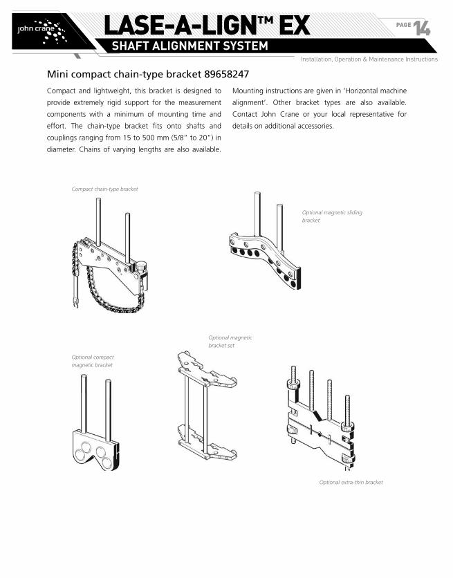
Mini compact chain-type bracket 89658247
Compact and lightweight, this bracket is designed to
provide extremely rigid support for the measurement
components with a minimum of mounting time and
effort. The chain-type bracket fits onto shafts and
couplings ranging from 15 to 500 mm (5/8” to 20”) in
diameter. Chains of varying lengths are also available.
Mounting instructions are given in ‘Horizontal machine
alignment’. Other bracket types are also available.
Contact John Crane or your local representative for
details on additional accessories.
Compact chain-type bracket
Optional magnetic sliding
bracket
Optional compact
magnetic bracket
Optional extra-thin bracket
Optional magnetic
bracket set
LASE-A-LIGN™ EXSHAFT ALIGNMENT SYSTEM
Installation, Operation & Maintenance Instructions
PAGE14

Connection of peripheral devices
( PC, printer , USB stick, and
power supply) to an intrinsically
safe LASE-A-LIGN EX Shaft
Alignment System can only
take place via the adapter box
89658232 The adapter box must
under no circumstances be used
in a hazardous area.
The USB memory stick
89658237 is connected to the
adapter box using the USB cable
89658240.
Note: No other device is to be
connected to this specific port.
Connected to printer using the USB A/B cable 89658240
Connected to PC using the USB A/B cable 89658240
Note: The USB memory stick and
printer interfaces cannot be used
simultaneously.
LASE-A-LIGN EX Shaft Alignment
System AC power supply 89658236
Interface for data exchange with a PC/printer and power supply to an
intrinsically safe LASE-A-LIGN EX Shaft Alignment System computer.
e
LASE-A-LIGN™ EXSHAFT ALIGNMENT SYSTEM
Installation, Operation & Maintenance Instructions
PAGE15
Configuration and data management
Shortcut numbers
LASE-A-LIGN EX Shaft Alignment System menu items
are accessed using the navigation keys. The navigation
direction is either upwards/downwards or sideways.
Alternatively, use may be made of the data entry keys
which provide navigation shortcuts.
NOTE: All context menu items are labeled with
digits for quick access. The required menu item
is accessed directly by pressing the corresponding
data entry key.
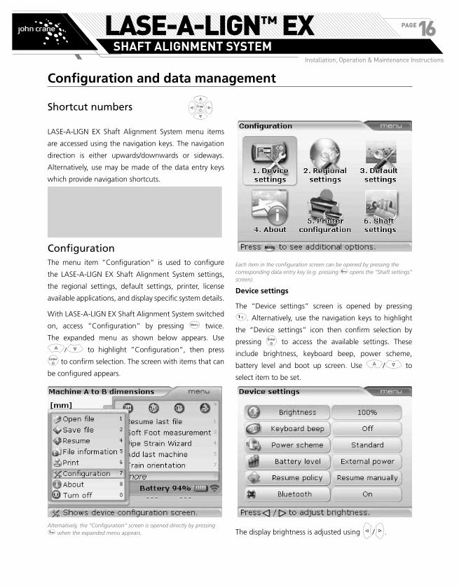
ConfigurationThe menu item “Configuration” is used to configure
the LASE-A-LIGN EX Shaft Alignment System settings,
the regional settings, default settings, printer, license
available applications, and display specific system details.
With LASE-A-LIGN EX Shaft Alignment System switched
on, access “Configuration” by pressing q twice.
The expanded menu as shown below appears. Use
f/g to highlight ”Configuration”, then press
e to confirm selection. The screen with items that can
be configured appears.
Alternatively, the “Configuration” screen is opened directly by pressing 7 when the expanded menu appears.
Each item in the configuration screen can be opened by pressing the corresponding data entry key (e.g. pressing 6 opens the “Shaft settings” screen).
Device settings
The “Device settings” screen is opened by pressing
1. Alternatively, use the navigation keys to highlight
the “Device settings” icon then confirm selection by
pressing e to access the available settings. These
include brightness, keyboard beep, power scheme,
battery level and boot up screen. Use f/g to
select item to be set.
The display brightness is adjusted using h/i.
LASE-A-LIGN™ EXSHAFT ALIGNMENT SYSTEM
Installation, Operation & Maintenance Instructions
PAGE16

Each item in the configuration screen can be opened by pressing the corresponding data entry key (e.g. pressing 6 opens the “Shaft settings” screen).
Device settings
The “Device settings” screen is opened by pressing
1. Alternatively, use the navigation keys to highlight
the “Device settings” icon then confirm selection by
pressing e to access the available settings. These
include brightness, keyboard beep, power scheme,
battery level and boot up screen. Use f/g to
select item to be set.
The display brightness is adjusted using h/i.
To turn the keyboard beep on/off, press e. The on/
off box appears. Use f/g to select either “on”
(to enable the beep) or “off” (to dis-enable the beep).
Press e to confirm selection.
The power scheme option is used to select setting that
manages the power usage in LASE-A-LIGN EX Shaft
Alignment System. The four available options are:
“Standard” (the display dims after 10 minutes and shuts
down after 1 hour), “Full power” (no dimming and no
shutdown), “Use standby” (no dimming and shutdown
is after 1 hour) and “Long life” (the display dims after
3 minutes and shutdown takes place after 10 minutes).
The required setting is selected using f/g and
confirmed by pressing e.
The capacity of the battery appears next to the battery
level bar. The item is also used to carry out a Li-ion
battery test for service and trouble shooting purposes.
This utility is accessed by pressing e with “Battery
level” highlighted.
“Resume policy” allows the user to specify the mea-
surement file that opens when LASE-A-LIGN EX Shaft
Alignment System is turned on. The system may be set
to open the last used measurement file (‘Always resume
last file’) or open a new measurement file (‘Resume
manually’). With “Resume policy” highlighted, press e
to display the available resume options. Use f/g
to highlight preferred resume option. Confirm selection
by pressing e.
LASE-A-LIGN™ EXSHAFT ALIGNMENT SYSTEM
Installation, Operation & Maintenance Instructions
PAGE17
The item ‘Bluetooth’ is used to enable or dis-enable
the Bluetooth capabilities of the LASE-A-LIGN EX Shaft
Alignment System computer. To turn Bluetooth capabil-
ities on/off, press e with the item highlighted. The on/
off box appears. Use f/g to select either ‘on’ (to enable
Bluetooth capabilities) or ‘off’ (to dis-enable Bluetooth
capabilities), then press e to confirm selection.
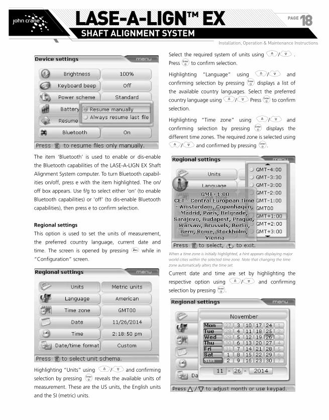
Regional settings
This option is used to set the units of measurement,
the preferred country language, current date and
time. The screen is opened by pressing 2 while in
“Configuration” screen.
Highlighting “Units” using f/g and confirming
selection by pressing e reveals the available units of
measurement. These are the US units, the English units
and the SI (metric) units.
Select the required system of units using f/g .
Press e to confirm selection.
Highlighting “Language” using f/g and
confirming selection by pressing e displays a list of
the available country languages. Select the preferred
country language using f/g Press e to confirm
selection.
Highlighting “Time zone” using f/g and
confirming selection by pressing e displays the
different time zones. The required zone is selected using
f/g and confirmed by pressing e.
When a time zone is initially highlighted, a hint appears displaying major
world cities within the selected time zone. Note that changing the time
zone automatically alters the time set.
Current date and time are set by highlighting the
respective option using f/g and confirming
selection by pressing e.
LASE-A-LIGN™ EXSHAFT ALIGNMENT SYSTEM
Installation, Operation & Maintenance Instructions
PAGE18

Use h/i to highlight either date, month or year.
Set the date using the data entry keys and confirm entry
using either ß or e. Alternatively, both date and time
can be set using f/g.
The format in which the date or time is displayed is set
via the item “Date/time format”. Open regional settings
by pressing 2. Use f/g to highlight the menu
item ‘Date/time format’.
Pressing e with ‘Date/time format’ highlighted reveals
a menu box with the items ‘Date format’ and ‘Time
format’. Use f/g to select either item, confirm-
ing selection by pressing e.
The time format is used to set either the 12h or 24h
notation. The selected notation is confirmed by pressing
e. The date format is used to set dd-mm-yyyy or mm/
dd/yyyy format.
LASE-A-LIGN™ EXSHAFT ALIGNMENT SYSTEM
Installation, Operation & Maintenance Instructions
PAGE19
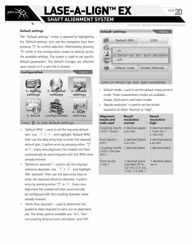
Default settings
The “Default settings” screen is opened by highlighting
the ‘Default settings’ icon use the navigation keys then
pressing e to confirm selection. Alternatively, pressing
3 while in the configuration screen to directly access
the available settings. The screen is used to set specific
default parameters. The default changes are effective
upon restart or if a new file is created.
� ‘Default RPM’ – used to set the required default
rpm. Use f/g and highlight ‘Default RPM’
then use the data entry keys to enter the required
default rpm. Confirm entry by pressing either e
orß. Every new alignment file created will then
automatically be preconfigured with this RPM value
already entered.
� ‘Reference diameter’ – used to set the required
reference diameter. Use f/g and highlight
‘Ref. diameter’ then use the data entry keys to
enter the required reference diameter. Confirm
entry by pressing either e or ß. Every new
alignment file created will then automatically
be configured with this coupling diameter value
already entered.
� ‘Work-flow assistant’ – used to determine the
guidance steps required to carry out an alignment
job. The three options available are: ‘On’, ‘Sen-
sor-coupling distance auto calculation’ and ‘Off’.
� Default mode – used to set the default measurement
mode. Three measurement modes are available –
Sweep, Multi-point and Static modes.
� ‘Results resolution’ is used to set the results
resolution at either ‘Normal’ or ‘High’.
Alignment results and units used
Result resolution normal
Result resolution high
Coupling results ( mm / mrad )
2 decimal places x.xx mm
3 decimal places ( 1 µm res. ) x. xxx mm
Foot results ( mm )
2 decimal places x.xx mm
2 decimal places x.xx mm
Coupling results ( mils / mils per inch )
1 decimal place 1 decimal place
Foot results ( mils )
1 decimal place rounded off to 1/2 mil ( 0.5 mil, 1 mil, 1.5 mils )
1 decimal place xxx.x
LASE-A-LIGN™ EXSHAFT ALIGNMENT SYSTEM
Installation, Operation & Maintenance Instructions
PAGE20

Printer configuration
This option is used to set up printers and the printing
configuration in LASE-A-LIGN EX Shaft Alignment
System. The “Printer configuration” screen is opened
by pressing 5 while in the configuration screen.
Alternatively, use the navigation keys to highlight the
‘Printer configuration’ icon then confirm selection by
pressing e to access the printer configuration screen.
The default printer type is ‘PDF file’. With this configuration, the
measurement report is saved as a PDF to the approved memory stick. For
the intrinsically safe LASE-A-LIGN EX Shaft Alignment System computer
89658208, the printing must be done via the adapter box 89658232.
Four printing options can be set using “Printer
configuration”.
“Type” – Selecting “Type” and then pressing e
displays a list with all supported printers.
“Paper” – Used to select the required paper size
“Orientation” – Used to set the paper orientation.
Select “Portrait” for a vertical layout and
“Landscape” for a horizontal layout.
“Color mode” – Used to set the color mode in
which the measurement report is to be printed.
This can either be in full color or in gray-scale.
89658237
89658232
89658208
89658208 (ALI 12.200 EX)
The configuration opposite
shows how a measurement
report is saved as PDF to the
approved memory stick from an
intrinsically safe LASE-A-LIGN
EX Shaft Alignment System
computer 89658208 (ALI 12.200
EX) .
e
LASE-A-LIGN™ EXSHAFT ALIGNMENT SYSTEM
Installation, Operation & Maintenance Instructions
PAGE21

Shaft settings
The “Shaft settings” screen is opened by pressing 6
while in the configuration screen. Alternatively, use
the navigation keys to highlight the ‘Shaft settings’
icon then confirm selection by pressing e to access
the available settings. The screen is used to set specific
shaft alignment parameters. The settings are effective
immediately.
� All-in-one results – used to activate or deactivate
the option to display both feet and coupling results
within a single screen
� Default rpm – used to set the desired default rpm
� Reference diameter – used to set the desired
reference diameter
� Tolerance table – the available options are 50 Hz
and 60 Hz. The mains supply frequency determines
the standard rpm values that appear in the
tolerance table. Tolerance values based on these
frequencies may be read off the suggested John
Crane Alignment tolerance table.
� Auto sweep – used to activate or deactivate
‘auto sweep’ [if deactivated, continuous sweep
measurement takes place only after pressing e]
Data managementLASE-A-LIGN EX Shaft Alignment System possesses an
effective file and data management facility. The file and
data management options are accessed by pressing q
twice.
Use h/i to cycle the cursor between the two panes.
Note: By “cursor”, we are referring to the orange highlight bar.
Use h to access the box with the file and data man-
agement options. These are “Open file”, “Save file”,
“New file”, “Print” and “About”.
“Open file” – This option is used to load any stored file.
Pressing 1 with the cursor on the left pane reveals a
list consisting all stored files.
Alternatively, the “Open file” option may be accessed in the set-up screen
above using the navigation keys to highlight “Open file” then pressing e.
Use f/g to highlight file to be opened and press
e to open the file.
LASE-A-LIGN™ EXSHAFT ALIGNMENT SYSTEM
Installation, Operation & Maintenance Instructions
PAGE22

“Save file” – This option is used to save the current file.
If the file is new and does not yet have a name, use the
data entry keys to enter the new file name in the editing
box that appears.
Press either ß or e to confirm file name.
If the file name already exists, the editing box appears
with the existing file name highlighted. This may be
overwritten or replaced with a new file name.
“New file” – This option is used to create a new mea-
surement file.
“Print” – This option is used to save the measurement
report as PDF directly to a memory stick or print the
report or the soft foot measurement report using any
one of the available printers.
The following report options are available:
› Complete report – this option prints a complete
report that includes machine graphics and
measurement results in both numerical and
graphical format.
› Graphical report – reports printed using this
option display only graphical representation
› Text report – this option generates reports only in
text format
› Pipe strain measurement report – this option is
used to generate the pipe strain check report
› Change printer to configured printer – this
item is used to toggle between the default
setting “PDF file” and the configured printer.
To configure a new printer, press q while
on this screen followed by 3, then proceed
as described under “Printer configuration”
previously.
LASE-A-LIGN™ EXSHAFT ALIGNMENT SYSTEM
Installation, Operation & Maintenance Instructions
PAGE23
Getting started
Set up LASE-A-LIGN EX Shaft
Alignment System1. Prepare the machines by making certain that they
are locked out, tagged out and all necessary safety
precautions have been taken.
2. Mount brackets, transducer and reflector. The
transducer should be mounted on the stationary
machine.
3. Connect cable and switch on LASE-A-LIGN EX Shaft
Alignment System by pressing e and holding
down briefly. All four LEDs light up and the start
screen pops up. Shortly afterwards, the machine
dimensions screen is displayed.
Enter dimensionsUse the data entry keys to directly enter all required
dimensions.
The editing The editing box appears as soon as a data
entry key is pressed. Confirm entry by pressing e. The
rectangular highlight box moves to the next dimension.
The navigation keys can also be used to cycle through
all dimensions.
Dimensions to be entered include:
1. Transducer-to-reflector
2. Transducer-to-coupling center
3. Coupling diameter (default is 100 mm / 10” {for US
units})
4. RPM (default is 1500 / 1800 {for US units})
5. Coupling center-to-front foot (right machine)
6. Front foot-to-back foot (right machine)
Measure
Press m to proceed with measurement. Initially center
the beam on the reflector dust cap. With the dust cap
on, ‘laser off‘ appears on the screen with the RED LASE-
A-LIGN EX Shaft Alignment System computer LED lit.
� Avoid looking directly at the laser beam.
Adjust bracket if necessary to center beam horizontally
onto the reflector. Tighten bracket. Slide the reflector
on the support posts to center beam vertically onto the
reflector dust cap. When centered, remove the reflector
dust cap.
Use the yellow knob to
make horizontal adjust-
ments of the reflected
laser beam, and the
thumbwheel to make
vertical adjustments to
position the dot at the
center of the target square or as near the center as
possible.
Transducer
Reflector
s
LASE-A-LIGN™ EXSHAFT ALIGNMENT SYSTEM
Installation, Operation & Maintenance Instructions
PAGE24

NOTE: When making the above adjustments, ob-
serve the LASE-A-LIGN EX Shaft Alignment System
computer LEDs and the dot on the display screen.
The green LED lights up to indicate that the reflect-
ed beam position is OK and measurement can be
made. The blue LED lights up when the dot is cen-
tered in the target square.
After centering the laser beam, rotate shafts to auto-
matically initiate continuous sweep measurement mode
which is the default mode.
Rotate the shafts as through a complete turn or as far as
possible. A minimum rotation of at least 60° is required.
Press e to finish measurement.
ResultsPress k to view alignment results.
The ‘all-in-one’ results screen activated under shaft settings shows both
vertical and horizontal coupling and foot results.
Coupling results are given in the form of gap and
offset. With stationary machine on the viewer’s left,
gap is positive when open at the top or side away from
viewer. Offset is positive when the movable machine is
higher or further away from viewer.
Individual vertical and horizontal foot and coupling
results are accessed by pressing either k or hori.
Vertical position results (the Tick indicates alignment within tolerance)
LASE-A-LIGN™ EXSHAFT ALIGNMENT SYSTEM
Installation, Operation & Maintenance Instructions
PAGE25

Horizontal position results (a Cross indicates alignment out of tolerance)
Both vertical and horizontal results show the foot
position relative to the stationary machine centerline.
Positive values indicate that right machine is upwards
or away from viewer. Negative values indicate that
right machine is downwards or towards the viewer.
The alignment condition is indicated by the tolerance
symbol.
(LED lights up green) - values in accepted
tolerances
(LED lights up red) - values out of tolerance
LASE-A-LIGN™ EXSHAFT ALIGNMENT SYSTEM
Installation, Operation & Maintenance Instructions
PAGE26

Horizontal machine alignment
1. Preparing for the alignment
procedure Before using LASE-A-LIGN EX Shaft Alignment System,
prepare the machine for alignment as described below.
Make sure machines are locked out and tagged out
and cannot be started accidentally or deliberately
while you are working on them!
a. Solid, flat foundation
A solid, rigid foundation is required to obtain correct,
lasting shaft alignment that allows long-term uninter-
rupted machine service.
b. Machine mobility
If the machine to be moved stands directly on the foun-
dations, it cannot be lowered for alignment correction. It
is therefore advisable to start with about 2 mm (50 mils)
of shims beneath the feet of both machines. Hydraulic
or screw-type positioning aids are recommended for
horizontal movement.
c. Rigid couplings
Rigid couplings must be loosened before measurement
so that they do not distort the alignment condition.
d. Shaft play and coupling backlash
Axial shaft play of up to 3 mm (1/8”) has no adverse
effect on alignment results (but not necessarily for
machine operation!).
Because of the measuring principle, turning the shaft or
coupling end where the reflector is mounted eliminates
the effects of coupling backlash, as readings are taken
only when the transducer moves.
e. Soft foot
Soft foot causes the machine frame distortion every
time the anchor bolts are tightened, making proper
alignment difficult or impossible.
f. Thermal growth, alignment targets, tolerances
These values can be obtained from the individual
machine specifications, and then entered into the
program.
g. Measurement separation
Since LASE-A-LIGN EX Shaft Alignment System requires
no mechanical connections (such as cantilevered dial
indicator brackets) to span over the coupling during
measurement, alignment may easily be performed over
large transducer–reflector separations.
Note: A maximum transducer-reflector separation of 5 m (16 feet) is
recommended.
Note that over very large distances the shafts and
coupling may sag, and the machines may need to be
deliberately misaligned to take this into account, if
such sag does not disappear when machines are put
into operation. Refer to the machine manufacturer’s
specifications.
2. Check for soft footRefer to section on soft foot on page 27.
3. Mount the brackets
Mount the brackets on either side of the machine
coupling, and both at the same rotational position.
Please note the following in order to obtain the highest
possible measurement accuracy and to avoid damage
to equipment:
• Ensure that the brackets fit solidly onto their
mounting surfaces!
• Do not use self-constructed mounting brack-
ets, or modify the original bracket configuration
supplied by John Crane (for example, do not use
support posts longer than those supplied with the
bracket).
s
a
s
LASE-A-LIGN™ EXSHAFT ALIGNMENT SYSTEM
Installation, Operation & Maintenance Instructions
PAGE27

Bracket mounting procedure
To fit the compact bracket chains, refer to the diagram
shown below and follow the instructions carefully.
1. Choose the shortest support posts which will still
allow the laser beam to pass over the coupling
flange. Insert the support posts into the bracket.
NOTE: In some cases, if the coupling is large
enough, a coupling bolt can be removed and the
laser beam shot through the bolt hole, in order to
avoid protruding radially beyond the coupling’s
outer diameter (OD).
2. Fasten them in place by tightening the hex screws
on the sides of the bracket frame.
3. Place the bracket on the shaft or coupling. Wrap
the chain around the shaft and feed it through the
other side of the bracket: if the shaft is smaller than
the width of the bracket frame, insert the chain
from the inside of the bracket as shown below; if
the shaft is larger than the bracket width, insert the
chain into the frame from the outside.
4. Catch the chain loosely on the anchor peg.
5. Turn the bracket thumbnut to tighten the assembly
onto the shaft.
6. Clip the loose end of the chain back onto itself.
The bracket should now be tight upon the shaft. Do not
push or pull on the bracket to check, since this could
loosen its mounting.
To remove the brackets, loosen the thumbnut, then
remove the chain from its anchor peg.
NOTE: The compact chain-type brackets cover
most situations, but in cramped or special cases,
other types of brackets may be required. Please
contact your John Crane representative for details.
4. Mount the EX Bluetooth Module,
Transducer and ReflectorThe intrinsically safe EX Bluetooth module passes
alignment readings from the intrinsically safe measure-
ment sensor to the LASE-A-LIGN EX Shaft Alignment
System computer internal antenna. The module
covers direct line of sight distances of up to 10 m / 33’
depending on the prevailing environmental conditions.
Its electronic compartment complies with code IP65
(dust tight and protected against water jets). The intrin-
sically safe EX Bluetooth module is powered using 2 ‘AA’
size batteries. The operating time for the batteries is 14
hours – based on an operating cycle of 50% measure-
ment, 50% standby.
LASE-A-LIGN™ EXSHAFT ALIGNMENT SYSTEM
Installation, Operation & Maintenance Instructions
PAGE28

� The intrinsically safe EX Bluetooth module
89658230 (ALI 12.100 EX) must only be connected
with the intrinsically safe sensors
89658230 (ALI 12.100 EX) TÜV 07 ATEX 554148
� Only use 1.5 V AA MN 1500 batteries from
Duracell.
� Each individual battery is intrinsically safe.
Batteries can be changed within the explosive
area. When handling batteries with the explosive
area, necessary precaution must be taken to avoid
short-circuiting the battery terminals.
� The intrinsically safe EX Bluetooth module does not
require maintenance.
� The circuit parameters meet the intrinsic safety
requirements Ex ib IIC.
� The maximum cable length between the intrinsi-
cally safe EX Bluetooth module and the sensor not
exceed 1 m.
� The installation and operation of the intrinsically
safe LASE-A-LIGN EX Shaft Alignment System must
be in accordance with the European regulations (EN
60079-10-1:2009 ff) and equipment safety law as
well as the general recognized rules of the technol-
ogy and the operating manuals 89658257.
� The most current regulations regarding servicing,
maintenance and testing, as they appear in ElexV
§ 13, EN 60079-14 and EN 60079-17 must be
observed. The rules of the manufacturer as they
appear in this manual must also be observed.
Mounting the EX Bluetooth module
Connect the cable 89658274 to the EX Bluetooth
module 89658259 (ALI 4.621 EX) by inserting the longer
90-degree connector of the cable into the four-pin
socket on the side of the module with a groove.
NOTE: Match the red dot on the plug to the groove
on the socket to ensure proper plug orientation.
Mount the EX Bluetooth module on the support posts
of the bracket fixed on the shaft of the left machine
(usually stationary machine) as shown in the figure
below. The module slides onto the support posts and is
held in place by friction fit. It is recommended to mount
the EX Bluetooth module on to the bracket frame.
Mount transducer
Mount the transducer on the support posts of the
bracket fixed on the shaft of the left machine (usually
stationary machine) – as viewed from normal working
position. Ensure that its yellow knobs are loosened
enough to let you slide the housing onto the support
posts with the cable side downward.
Clamp the transducer onto the support posts by tight-
ening the yellow knobs. Ensure that the laser can pass
over or through the coupling and is not blocked.
2. Tighten the yellow knobs.1. Loosen the yellow
knobs and push the
transducer down onto
the posts.
Writing ß using ANSI code:Press Alt then type 0223 =
ß
LASE-A-LIGN™ EXSHAFT ALIGNMENT SYSTEM
Installation, Operation & Maintenance Instructions
PAGE29

Mount reflector
a. Mount the reflector on the support posts of the
bracket fixed on the shaft of the right machine (usually
move-able machine) – as viewed from normal working
position.
The yellow knob on the front of the reflector allows
you to adjust the horizontal angle of the reflected laser
beam. Before you mount the reflector make sure that
this knob is centered to allow for maximum adjustment
range later on. The bottom of the knob should be flush
with the arrow marking on the reflector housing.
b. Flip up the quick-release lever on the side of the
reflector housing, then slide the reflector onto the right-
hand bracket posts. Return the lever to its horizontal
position to secure the reflector on the posts.
Both transducer and reflector should be at the same
height, as low as possible, yet just high enough for the
beam to clear the coupling flange. They should also
visually appear to be parallel to each other.
Make the final adjustments, loosening the brackets
slightly if necessary, then rotating them and
re-tightening.
5. Switch LASE-A-LIGN EX Shaft
Alignment System on and start
applicationAlignment System on and start application
Press e and hold down for a few seconds. The 4
alignment condition LEDs and the EX Bluetooth indicator
LED light up. Shortly afterwards, the splash screen
appears, followed by the shaft alignment machine
dimensions screen.
6. Switch the EX Bluetooth
module onAfter mounting the sensor on the support posts, connect
the module to the sensor by inserting the opposite end
of the cable into the 8-pin sensor socket, noting the
keyway orientation.
The operating time LEDs blink for 3 seconds. The module
is now ready for operation. When the intrinsically safe
EX Bluetooth module is switched on, it supplies power
to the sensor. If no measurement action is activated in
the intrinsically safe computer, the power supply to the
sensor stops.
Operating time LED indicators
State of LEDs Indicates
3 LEDs lit continuously Operating time is between 75%–100%
2 LEDs lit continuously Operating time is between 50%–75%
1 LED lit continuously Operating time is between 25%–50%
Only 1 LED blinking
(slowly)
Operating time is under 25%
Only 1 LED blinking
(very fast)
Operating time in critical phase.
Measurement should not be taken
LASE-A-LIGN™ EXSHAFT ALIGNMENT SYSTEM
Installation, Operation & Maintenance Instructions
PAGE30

Establishing wireless communication between the
intrinsically safe sensor and computer
a) After entering machine dimensions as described in
the product specific operating instructions, press m.
The measurement screen as shown below appears.
b) Press q to access the context menu so as to choose
the desired data transmission mode. Use f/g
to highlight ‘Sensor selection’.
c) Press e to confirm selection. The selection screen
appears. Use f/g to highlight ‘Scan’.
d) Press e to scan the neighbourhood for any intrinsi-
cally safe EX Bluetooth modules.
e) After the scanning process is completed, any intrin-
sically safe EX Bluetooth modules detected will be
listed. Use f/g to highlight the connected
intrinsically safe EX Bluetooth module.
f) Press e to confirm selection and proceed with
measurement.
LASE-A-LIGN™ EXSHAFT ALIGNMENT SYSTEM
Installation, Operation & Maintenance Instructions
PAGE31

Changing data transmission mode from intrinsi-
cally safe EX Bluetooth module to cable [only
possible with 89658230 (ALI 12.100 EX)]
a) Repeat steps 3a) and 3b), then press e to confirm
selection.
b) Use f/g to select ‘Port1’ for cable transmission.
c) Press e to confirm selection and proceed with
measurement.
7.1 Enter machine dimensionsMachine information and dimensions are entered using
the gray data entry keys.
The required missing dimensions are entered directly
using the data entry keys. With the missing dimension
highlighted, enter dimension by pressing the appropri-
ate data entry keys. The editing box appears as soon as
the first key is pressed.
Confirm the entered value by pressing e. The highlight
advances automatically to the next missing dimension.
Alternatively, any dimension can be accessed by using
the navigation keys.
The dimensions to be entered vary according to machine
and type of coupling. In a standard horizontal alignment
application enter dimensions as follows:
7.1.1 Transducer to reflector
This is the distance between the markings on top of the
transducer and the reflector.
7.1.2 Transducer to coupling center
This is the distance between the marking on top of the
transducer and the coupling center.
This dimension is calculated automatically from the
entered transducer to reflector distance. Should there
be need to edit the value, proceed by highlighting
it using the navigation keys. Press e to activate the
editing box, and then use the data entry keys to edit
the value.
LASE-A-LIGN™ EXSHAFT ALIGNMENT SYSTEM
Installation, Operation & Maintenance Instructions
PAGE32
7.1.3 Coupling diameter
The coupling diameter can be obtained by measuring
the circumference of the coupling and dividing the value
by 3.142 (pi).
The default value is 100 mm (10” if set to US units).
Should there be need to edit the value, use the naviga-
tion keys to highlight the value, then use the data entry
keys to edit the value. Confirm the value by pressing
e. The highlighting box advances to the next required
missing distance automatically.
7.1.4 RPM (revolutions per minute)
The default value is 1500 (1800 if set to US units).
Should there be need to edit the value, press e with
the dimension highlighted to activate the editing box,
and proceed to edit using the data entry keys.
7.1.5 Coupling center to front foot, right machine
This is the distance from the center of the coupling to
the pair of feet on the right machine nearest to the
coupling.
7.1.6 Front foot to back foot, right machine
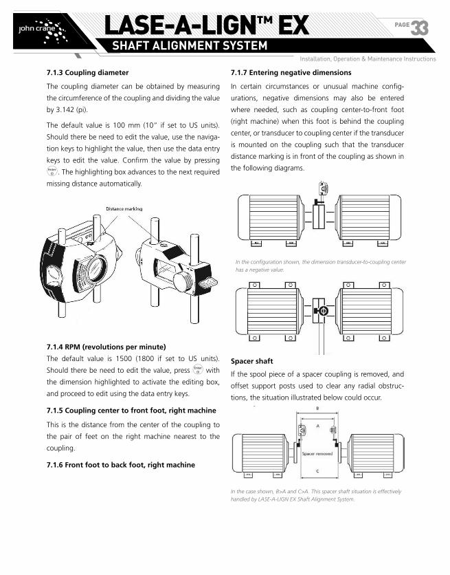
7.1.7 Entering negative dimensions
In certain circumstances or unusual machine config-
urations, negative dimensions may also be entered
where needed, such as coupling center-to-front foot
(right machine) when this foot is behind the coupling
center, or transducer to coupling center if the transducer
is mounted on the coupling such that the transducer
distance marking is in front of the coupling as shown in
the following diagrams.
Spacer shaft
If the spool piece of a spacer coupling is removed, and
offset support posts used to clear any radial obstruc-
tions, the situation illustrated below could occur.
In the case shown, B>A and C>A. This spacer shaft situation is effectively
handled by LASE-A-LIGN EX Shaft Alignment System.
In the configuration shown, the dimension transducer-to-coupling center
has a negative value.
LASE-A-LIGN™ EXSHAFT ALIGNMENT SYSTEM
Installation, Operation & Maintenance Instructions
PAGE33
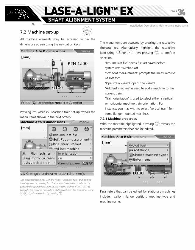
7.2 Machine set-up
All machine elements may be accessed within the
dimensions screen using the navigation keys.
Pressing q while in “Machine train set-up reveals the
menu items shown in the next screen.
The expanded sub-menu with the items ‘Horizontal train’ and ‘Vertical
train’ appears by pressing 7. The required orientation is selected by
pressing the appropriate shortcut key. Alternatively use f/g to
highlight the required menu item, shifting between the two panes using
h/i. Confirm selection by pressing e.
The menu items are accessed by pressing the respective
shortcut key. Alternatively, highlight the respective
item using forg then pressing e to confirm
selection.
‘Resume last file’ opens file last saved before
system was switched off.
‘Soft foot measurement’ prompts the measurement
of soft foot.
‘Pipe strain wizard’ opens the wizard.
‘Add last machine’ is used to add a machine to the
current train.
‘Train orientation’ is used to select either a vertical
or horizontal machine train orientation. For
instance, you may wish to select ‘Vertical train’ for
some flange-mounted machines.
7.2.1 Machine properties
With the machine highlighted, pressing e reveals the
machine parameters that can be edited.
Parameters that can be edited for stationary machines
include: fixation, flange position, machine type and
machine name.
LASE-A-LIGN™ EXSHAFT ALIGNMENT SYSTEM
Installation, Operation & Maintenance Instructions
PAGE34

7.2 Machine set-up
All machine elements may be accessed within the
dimensions screen using the navigation keys.
Pressing q while in “Machine train set-up reveals the
menu items shown in the next screen.
The expanded sub-menu with the items ‘Horizontal train’ and ‘Vertical
train’ appears by pressing 7. The required orientation is selected by
pressing the appropriate shortcut key. Alternatively use f/g to
highlight the required menu item, shifting between the two panes using
h/i. Confirm selection by pressing e.
To choose type of machine to be displayed, using
f/g highlight ‘Choose machine type’ then press
e to confirm selection. The ‘Machine selection’ pane
opens.
Alternatively press 8 with the context menu displayed. The machine
selection pane appears.
Use f/g to scroll through the available machine
type graphics. Following machine graphics are available:
pump, motor, gearbox and a generic standard machine.
If you need to change the orientation of the machine
graphic usei/h.
If a machine is defined as move-able, the parameters
that can be edited include: fixation, flange position,
thermal growth values and machine name. Soft foot
measurement can also be carried out from the set-up
screen.
To edit the machine name, use f/g to highlight
‘Enter name’
Alternatively press 0 with the context menu displayed. The editing box
appears.
Confirm selection by pressing e. The editing box
appears and the machine name may be edited.
Use the data entry keys to edit the machine name.
Thermal growth values can be entered only when the
machine is defined as move-able. To enter thermal
growth values, highlight ‘Thermal Growth’ using either
f or g.
LASE-A-LIGN™ EXSHAFT ALIGNMENT SYSTEM
Installation, Operation & Maintenance Instructions
PAGE35

Alternatively, access the ‘Thermal growth’ screen directly by pressing the shortcut key 7 with the context menu displayed.
Press e. The “Thermal growth” screen appears.
Use the navigation keys to highlight the ‘feet pair’
where thermal growth is to be entered. The editing box
appears when any data entry key is pressed. Use the
data entry keys to enter the thermal growth value in the
vertical orientation, cycling through the feet pairs using
the navigation keys.
The editing box may also be opened by highlighting a foot value using
the navigation keys then pressing e.
To enter values in the horizontal orientation, press q
while in the “Thermal growth” screen. The context
menu as shown below appears. Use f/g to
highlight ‘Horizontal thermal growth’.
Alternatively, access the horizontal thermal growth view directly by
pressing the shortcut key 4 with the context menu displayed.
Press e to confirm selection. The horizontal thermal
growth view opens. Now proceed to enter values as
described for vertical orientation previously.
LASE-A-LIGN™ EXSHAFT ALIGNMENT SYSTEM
Installation, Operation & Maintenance Instructions
PAGE36

The editing box may also be opened by highlighting a foot value using the
navigation keys then pressing e.
Carefully observe sign convention (+ and -) when entering thermal
growth values. Thermal growth values are NOT a target; instead they
represent the amount and direction of the anticipated movement that the
machine will undergo when put in operation.
After entering all values, Press to exit the particular
thermal growth screen.
To dis-enable thermal growth values, use the navigation
keys to highlight the green tick. With the green check
mark highlighted, press e. This dis-enables thermal
growth.
Alternatively, press q while in the ‘Thermal growth’
screen. The context menu appears.
Alternatively use f/g to highlight ‘Thermal growth’ then use h
to switch to the next pane. Highlight ‘Disable’ using f/g then
confirm dis-enabling values by pressing e.
Press 1 followed by 2 to dis-enable thermal growth
values.
Thermal growth values may be enabled from the opposite screen once
again by pressing e.
7.2.2 Thermal growth calculator
Machine conditions change from the time the machine
is off line to when it is running under normal operating
conditions. Some of these changes are due to process
forces (e.g. fluid pressures, airflow). The most notable
of these changes is the change in the temperature of
the machine bearings and supports. This is called the
machine’s thermal growth.
If no other values are available, the system may be used
to calculate thermal growth compensation. Thermal
growth is calculated from the material characteristics,
expected temperature difference and height of the shaft
centerline above the shim plane.
Thermal growth is calculated as follows:
Access the “Thermal growth” screen to the
machine whose thermal growth requires calculating
as described previously.
Press q while on the screen. The context menu
appears. Use f/g to select ‘Thermal growth
calculator’.
LASE-A-LIGN™ EXSHAFT ALIGNMENT SYSTEM
Installation, Operation & Maintenance Instructions
PAGE37

Press e. The thermal growth calculator pane appears.
Alternatively, the thermal growth calculator pane may be accessed directly
from the previous screen by pressing the shortcut key 7 with the
context menu displayed.
Use the navigation keys to highlight the ‘Material’
information box then press e to select type of
material using the drop down menu that appears.
Confirm selection by pressing e.
Use the navigation keys to highlight the respective
value boxes and enter directly, the ambient
temperature, the machine running temperature
and the distance from machine base to the shaft
centerline using the data entry keys.
In the example opposite, the motor material is cast iron, the ambient
temperature is 25°C, the machine running temperature is 120° C and the
distance from the bottom of the turbine feet to the shaft centerline is 70
cm. This gives a growth of 0.71 mm.
7.2.3 Coupling properties
Coupling properties are entered and edited in the same
manner as machine properties. Use the navigation keys
to highlight the coupling.
With the coupling highlighted, pressing e reveals the
coupling parameters that can be edited.
LASE-A-LIGN™ EXSHAFT ALIGNMENT SYSTEM
Installation, Operation & Maintenance Instructions
PAGE38

The menu may also be used to reset the coupling settings to default, i.e
rpm is 1500, coupling diameter is 100 mm and the tolerance table is based
on 50 Hz.
Coupling parameters that can be edited include:
coupling targets, [user defined tolerances] and required
coupling dimensions.
To enter coupling target values, press 1 with the menu
displayed. Alternatively, highlight “Targets” using either
f or g then press e. The “Coupling targets”
screen appears.
The editing box may also be opened by highlighting a value position using
the navigation keys then pressing e.
Carefully observe sign convention (+ and -) when entering target values.
Target values are NOT the anticipated thermal growth values; instead they
represent the amount and direction of the desired misalignment to be set
at the coupling to compensate for the anticipated movement the machine
will undergo when put in operation.
Use the navigation keys to highlight respective gap/offset
to be entered. Enter coupling target value directly using
the data entry keys. The editing box appears when any
data entry key is pressed. Confirm entry by pressing e.
It may be necessary to specify individual tolerances. This
is carried out using the menu item ‘Tolerances’.
The coupling parameters context menu is displayed by pressing e with
the coupling highlighted.
To enter user defined tolerance values, Use either f
or g to highlight ‘Tolerances’ then press e. The
“User defined tolerances” screen appears.
NOTE: If the “User defined tolerances” screen is
dis-enabled, activate it using the context menu
item ‘Enable tolerances’.
Alternatively, access the ‘User defined tolerances’ screen by pressing 3
while the coupling properties context menu is displayed.
In this example, the active tolerances are the user defined values. The
‘user’ button in the lower frame is yellow. The system tolerance table is
deactivated as can be seen from the grayed out Tick in the upper frame.
The ‘user’ button
LASE-A-LIGN™ EXSHAFT ALIGNMENT SYSTEM
Installation, Operation & Maintenance Instructions
PAGE39

Use the navigation keys to highlight gap or offset. Enter
user defined tolerance value directly using the data entry
keys. The editing box appears when any data entry key
is pressed. Confirm entry by pressing e.
The values entered above are independent of rpm.
When these values are enabled, that is when the ‘user’
button in the bottom frame is yellow, they override the
system tolerance table.
Alternatively, the user defined tolerances may be deacti-
vated by exiting the user defined tolerances frame. This
automatically enables the system tolerance table and
the Tick in the upper frame revert to yellow.
Press ß to exit the “User defined tolerances” screen.
NOTE: that the tolerance screen toggles between
“Tolerance table” and “User defined tolerances”.
The tolerance screen context menu items may be used
to deactivate the system tolerance values, and toggle
between the system tolerance values and user defined
tolerances.
Entering coupling target values as dial indicator
readings
Coupling target values given in terms of dial indicator
readings can be entered into LASE-A-LIGN EX Shaft
Alignment System for conversion to gap and offset. If
the function coupling targets is enabled, the converted
values are automatically taken into account when deter-
mining the alignment condition. To enter dial indicator
measurements proceed by pressing q while in the
“Coupling targets” screen.
The “Coupling targets” screen is accessed as described on pages 39.
When the context menu appears, press 2 to display
the “Dial gauge set-up”screen.
LASE-A-LIGN™ EXSHAFT ALIGNMENT SYSTEM
Installation, Operation & Maintenance Instructions
PAGE40

NOTE: that a hint to set up the dial gauge con-
figuration will appear followed by the “Dial gauge
set-up” screen.
The dial gauge configuration is set at the header. Use the navigation keys
to highlight the header then cycle through the various configurations by
pressing e with header highlighted.
Enter the required dimensions, and if known, the
amount of bracket sag.
Press ß to access the “Targets as dial gauge values”
display. Enter the dial indicator values in the respective
value boxes.
Press ß to display the target values, including any
bracket sag amounts entered in terms of gap and offset.
LASE-A-LIGN™ EXSHAFT ALIGNMENT SYSTEM
Installation, Operation & Maintenance Instructions
PAGE41

7.3 Laser beam adjustment
After entering all required dimensions, press m to start
the measurement process. The transducer and reflector
need to be adjusted so that the laser beam strikes the
reflector and is reflected back into the transducer.
Do not look into the laser transducer aperture!
7.3.1 Remove transducer cap
The laser beam is now on! Leave the reflector cap on.
When the beam strikes the cap it should be readily
visible. Should the beam be so far off target that it
misses the reflector completely, hold a sheet of paper in
front of the reflector to try and locate the beam.
NOTE: If using the wireless communications EX
Bluetooth module 89658259 (ALI 4.621 EX), con-
nect it to the transducer and turn it on at this point.
(For details please refer to the chapter “Using the
Wireless EX Bluetooth module”.) If the module has
not been scanned and recognized by the LASE-A-
LIGN EX Shaft Alignment System computer yet,
refer to the instructions in section 7.3.3 within this
chapter.
7.3.2 Adjust beam onto reflector cap
With the reflector dust cap still in place, adjust the beam
onto the center of the target:
NOTE:
› To adjust vertically slide the reflector and/or
transducer up and down along their support
posts. Use the thumbwheel on the side of the
reflector housing. To move the transducer,
loosen the yellow knobs.
› To adjust horizontally you will have to loosen
one of the brackets on the shaft and rotate it
slightly. Re-tighten.
7.3.3 Remove reflector cap and establish commu-
nication between the transducer and LASE-A-LIGN
EX Shaft Alignment System computer
LASE-A-LIGN EX Shaft Alignment System collects mea-
surement data using either the wireless EX Bluetooth
module 89658259 (ALI 4.621 EX) or via the RS232
interface. After removing the dust cap to allow the
beam strike the reflector and be reflected back to
the transducer, press q Use either f or g to
highlight ‘Sensor selection’.
Alternatively, the sensor seIection window is opened directly by pressing
7 with the context menu displayed.
Press e to confirm selection.
If using the RS232 interface, use either f or g to
highlight “Sensor @ Port 1 (RS232)”. Press e to
confirm selection, and proceed with laser beam
adjustment.
If using the wireless data transmission module (also
referred to as the wireless EX Bluetooth module), and it is
not already registered, proceed to scan for it by highlight-
ing “Scan” and then press e to scan the neighborhood
for any wireless EX Bluetooth modules.
s
LASE-A-LIGN™ EXSHAFT ALIGNMENT SYSTEM
Installation, Operation & Maintenance Instructions
PAGE42

After the scanning process is completed, any detected
module is listed as shown below.
NOTE: The wireless EX Bluetooth module complies with the conducted
and radiated emission limits of FCC rules part 15.247.
Use either f or g to highlight the connected
wireless EX Bluetooth module. Press e to confirm
selection, and proceed with laser beam adjustment.
If only one wireless EX Bluetooth module is detected
during scanning, it is connected automatically. The serial
number of the wireless EX Bluetooth module in use is
displayed on the screen during measurement.
All wireless EX Bluetooth modules found will be remem-
bered. It may be necessary to delete some of these
entries as they could no longer be in use. To delete
unwanted entries, access the ‘Sensor selection’ menu.
Use the navigation keys to highlight the wireless EX
Bluetooth module to be deleted and press c.
Modules deleted are remembered if detected during
scanning.
7.3.4 Adjust reflector until both transducer LEDs
blink together slowly and the green LASE-A-LIGN
EX Shaft Alignment System computer LED lights
The transducer has a red and a green LED to indicate
the beam adjustment condition. This condition is
simultaneously monitored on the LASE-A-LIGN EX Shaft
Alignment System LEDs.
NOTE: Make sure that the reflector and transduc-
er lens are clean. Use a soft lint-free cloth. A lens
cleaning cloth 89658250 is supplied.
When the reflected beam fails to strike the detector
surface, the red LASE-A-LIGN EX Shaft Alignment
System computer LED lights up and the red transducer
LED blinks quickly (0.3 s). The message ‘Laser OFF’
appears on the display screen. Adjust the reflected beam
using the reflector metal thumbwheel and the yellow
adjustment knob on the reflector as shown on the next
page. As the reflected beam strikes the edge of the
detector, the amber LASE-A-LIGN EX Shaft Alignment
System computer lights up with the red transducer LED
still blinking quickly. The message ‘Laser End’ appears on
the display screen. (Here it may be helpful to use a piece
of paper to trace the path of the reflected beam toward
the transducer.)
LASE-A-LIGN™ EXSHAFT ALIGNMENT SYSTEM
Installation, Operation & Maintenance Instructions
PAGE43
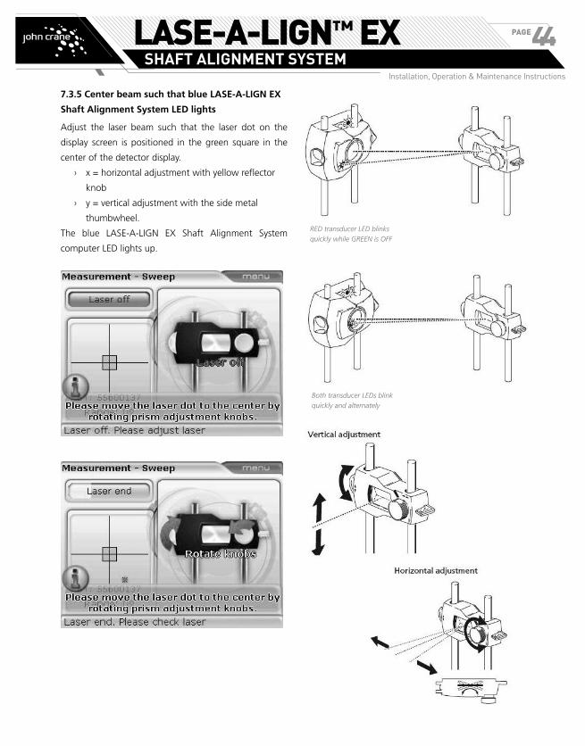
7.3.5 Center beam such that blue LASE-A-LIGN EX
Shaft Alignment System LED lights
Adjust the laser beam such that the laser dot on the
display screen is positioned in the green square in the
center of the detector display.
› x = horizontal adjustment with yellow reflector
knob
› y = vertical adjustment with the side metal
thumbwheel.
The blue LASE-A-LIGN EX Shaft Alignment System
computer LED lights up.
RED transducer LED blinks
quickly while GREEN is OFF
Both transducer LEDs blink
quickly and alternately
LASE-A-LIGN™ EXSHAFT ALIGNMENT SYSTEM
Installation, Operation & Maintenance Instructions
PAGE44
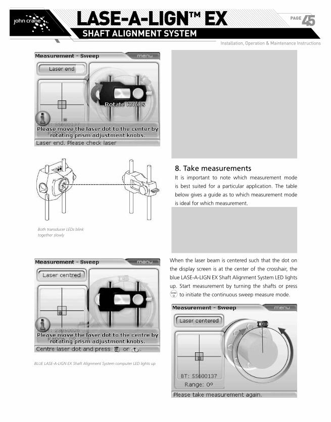
BLUE LASE-A-LIGN EX Shaft Alignment System computer LED lights up
NOTE: The beam does not have to be exactly at the
center of the crosshair, as this will not affect mea-
surement accuracy. However, maximum range for
measurement is available when the beam is well
centered.
Once centered, the transducer and reflector must
not be touched, as any movement during mea-
surement will be interpreted as misalignment.
These components may however be moved when
extending the measurement range (see ‘Alignment
options’ on page 67).
8. Take measurementsIt is important to note which measurement mode
is best suited for a particular application. The table
below gives a guide as to which measurement mode
is ideal for which measurement.
Measurement mode Application
Continuous sweep standard machines
Static measurement uncoupled shafts, nonrotatable shafts, vertical machines ( four feet or flange mounted)
When the laser beam is centered such that the dot on
the display screen is at the center of the crosshair, the
blue LASE-A-LIGN EX Shaft Alignment System LED lights
up. Start measurement by turning the shafts or press
e to initiate the continuous sweep measure mode.
Both transducer LEDs blink
together slowly
LASE-A-LIGN™ EXSHAFT ALIGNMENT SYSTEM
Installation, Operation & Maintenance Instructions
PAGE45

NOTE: Continuous measurement starts automati-
cally when the shafts begin to rotate.
The Continuous sweep measurement mode is the
default. (Refer to ‘Alignment options’ for static and
multipoint measurement modes.)
NOTE: If coupling torsion play (backlash) is sus-
pected, turn the shaft or coupling end where the
reflector is mounted. Ensure shaft is turned in the
normal rotation direction of the machine.
8.1 Turning shafts
To measure, rotate the shafts a full turn, or as far as
possible.
NOTE: Remember not to touch mounted com-
ponents! It is advised to turn shafts in the same
direction as the machine normally rotates, in case
the shafts shift from their normal seating in the
bearings.
You may begin measurement by turning the shafts
even if the beam is not centered exactly at the cen-
ter of the crosshair.
8.2 END or OFF? Extend
If laser END or Laser OFF appears on the screen during
the turning of the shafts, the laser has drifted out of the
detector due to great misalignment or long beam travel.
If this happens, then use the ‘Extend’ function (see page
67) to extend the measurement range.
NOTE: The ‘extend’ option is available only in
‘static’ measurement modes.
9. Results
Results are obtained after rotating the shaft through as
wide an angle as possible. As the shaft is rotated, the
covered arc changes color from red to yellow and finally
to green. A red sector signifies that the covered angle is
insufficient for accurate results. Results can be obtained
when the sector is yellow, but it is recommended that
the shafts be rotated until the arc is green.
Once measurement is completed, press k to view
alignment results.
9.1 Coupling results
How well is the machine aligned? How much misalign-
ment does the coupling have?
This complete alignment condition screen appears only when the option
‘All-in-one results’ is activated in the ‘Shaft settings’ configuration menu.
If not activated then the screen displays only coupling results.
LASE-A-LIGN™ EXSHAFT ALIGNMENT SYSTEM
Installation, Operation & Maintenance Instructions
PAGE46

9. Results
Results are obtained after rotating the shaft through as
wide an angle as possible. As the shaft is rotated, the
covered arc changes color from red to yellow and finally
to green. A red sector signifies that the covered angle is
insufficient for accurate results. Results can be obtained
when the sector is yellow, but it is recommended that
the shafts be rotated until the arc is green.
Once measurement is completed, press k to view
alignment results.
9.1 Coupling results
How well is the machine aligned? How much misalign-
ment does the coupling have?
This complete alignment condition screen appears only when the option
‘All-in-one results’ is activated in the ‘Shaft settings’ configuration menu.
If not activated then the screen displays only coupling results.
Coupling results are given in the form of gap and
offset values in both vertical and horizontal directions.
The true gap being the difference in gap between the
coupling faces top to bottom (vertical) or side to side
(horizontal) at the diameter that was entered. Offset on
the other hand is the distance between two lines at the
transmission plane of the coupling.
Sign convention
The following sign convention is used in the evaluation
of alignment results.
With left machine stationary, gap is positive when open
at top or side away from viewer. The viewer is consid-
ered to be standing in front of the machines as they
appear on the display.
Both vertical and horizontal results show the foot
position relative to the stationary machine centerline.
Positive values indicate that machine is upwards or away
from viewer. Negative values indicate that machine is
downwards or towards the viewer.
NOTE: If all four coupling values are within toler-
ance, you do not need to align the machines.
If no in-house standards or specifications from the
coupling or machine manufacturer are available, the
LASE-A-LIGN EX Shaft Alignment System computer LED
system and the Tick provides a tolerance check based
on standard industry norms. If the measured alignment
falls within acceptable tolerance, the green LED lights
up. The red LED lights up when alignment is out of
tolerance. In this case, the machines must be aligned.
9.2 Shaft and foot positions
If the coupling results show that misalignment exceeds
the tolerance, then the machine must be realigned
by shimming vertically and repositioning the machine
horizontally. The different views may be accessed by
pressing k/f/g.
The orange cursor at the foot position is cycled through all foot positions
using h/i. Any foot position can be designated static/unfixed by
pressing e with the position highlighted. Note that only two feet pairs
can be designated static at any one given time.
The horizontal results show that the machine front feet are to be moved 0.09 mm away from viewer and the rear feet moved 0.33 mm also away from viewer.
9.3 Alignment quality
The ‘Tick/Cross’ symbol on the foot results display
indicates the degree to which the measured alignment
condition meets tolerances. These are calculated from
the coupling tolerances. The Tick/Cross depicts either
alignment within tolerance or out of tolerance and
appears only when tolerances have been enabled.
(LED lights up green) - values in accepted
tolerances
(LED lights up red) - values out of tolerance
LASE-A-LIGN™ EXSHAFT ALIGNMENT SYSTEM
Installation, Operation & Maintenance Instructions
PAGE47
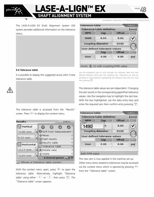
The LASE-A-LIGN EX Shaft Alignment System LED
system provides additional information on the tolerance
status.
NOTE:
Tolerance Tick/Cross Lit LED
Acceptable tolerance Tick Green
Out of tolerance Cross Red
� The Tick TAKES INTO ACCOUNT any targets
and thermal growth values which you may
have entered – see pages 36-37.
9.4 Tolerance table
It is possible to display the suggested active John Crane
tolerance table.
These suggested alignment tolerances are general
values based upon experience and should not be
exceeded. They are to be used only if existing in-
house standards or the manufacturer of the ma-
chine or coupling prescribe no other values.
The tolerance table is accessed from the “Results”
screen. Press q to display the context menu.
With the context menu open, press 5 to open the
tolerance table. Alternatively, highlight ‘Tolerance
table’ using either f or g then press e. The
“Tolerance table” screen appears.
Use the navigation keys to cycle through the tolerance table and user
defined tolerance items plus the tolerance tab. Tolerances can also be
activated or deactivated by highlighting the tolerance tab with the circle
then pressing e
The tolerance table values are rpm dependent. Changing
the rpm results in the corresponding gap/offset tolerance
values. Use the navigation key to highlight the rpm box.
With the box highlighted, use the data entry keys and
enter the required rpm then confirm entry pressing e.
The new rpm is now applied in the machine set-up.
Other menu items related to tolerances may be accessed
via the context menu which is opened by pressing q
from the “Tolerance table” screen.
a
LASE-A-LIGN™ EXSHAFT ALIGNMENT SYSTEM
Installation, Operation & Maintenance Instructions
PAGE48

� The context menu item ‘User tolerance’ is used to
set user defined gap and offset tolerance values.
When these defined values are active, the system
tolerance table is dis-enabled. The menu item
‘Disable tolerance’/’Enable tolerance’ is the used
to enable and dis-enable both system and user
defined tolerances.
� The tolerance table can be printed directly to the
configured printer or saved to a memory stick as
a PDF if the printer configuration is set to PDF
file. In this case, use is made of the adapter box
89658232 [for the intrinsically safe LASE-A-LIGN EX
Shaft Alignment System computer 89658208 (ALI
12.200 EX)].
10. Align machine
NOTE: Machines can be aligned using the given
foot results by proceeding as described below.
Remember, if alignment is in tolerance (indicated
by a Tick symbol and the green LASE-A-LIGN EX
Shaft Alignment System computer LED), there is
NO need to align the machines.
To align your machine you need to move it vertically
by shimming the feet, and horizontally by shifting it
sideways. You could do these operations in either order
or simultaneously, but the recommended procedure is
as follows:
10.1 Shim first
NOTE: It is recommended to perform vertical cor-
rections first, since the horizontal condition is easily
affected by the process of loosening anchor bolts
and inserting/removing shims, whereas the verti-
cal condition is less prone to being affected when
performing horizontal moves. You may need to re-
check soft foot before proceeding.
10.1.1 Preparation
To shim the machine successfully, ensure the following:
i. The foot bolts are clean, intact and removable.
ii. Soft foot has been eliminated.
iii. The feet have enough shims under them should
lowering the machine be necessary.
iv. Good quality shims are available from John Crane.
10.1.2 Loosen bolts
Avoid moving the machine horizontally. If any foot
comes off the ground when loosened, suspect soft foot.
10.1.3 Shim feet accordingly
Use the vertical results to shim BOTH front and back feet
as required. Negative feet values indicate that the machine
feet are low and therefore shims should be added, while
positive feet values suggest removal of shims.
NOTE: that vertical shimming can also be carried
out with the live vertical MOVE. (See section 10.3)
LASE-A-LIGN™ EXSHAFT ALIGNMENT SYSTEM
Installation, Operation & Maintenance Instructions
PAGE49

10.1.4 Re-tighten bolts
The machine should now have good vertical alignment.
10.1.5 Remeasure
Remeasure to verify vertical alignment results and
determine the exact alignment condition.
10.2 Horizontal live MOVE
Shimming usually involves the jacking up of the machine
and inserting or removing shims of known thicknesses.
(John Crane shims have the thicknesses indelibly etched
on them.)
The horizontal move is used for the lateral positioning
of the machine. This used to be done with a dial gauge
at the machine feet, but with the ‘MOVE’ function, you
can view the horizontal movement live on the display
screen.
10.2.1 Start live horizontal MOVE
While in results mode, press q. Use either f or
g to highlight “Move”.
Alternatively, press 1 to access Move directly.
With ‘Move’ highlighted, confirm selection by pressing
e. The Move selection dialog window appears. Use
either f or g to highlight “Horizontal” for
horizontal machine movement.
Confirm selection by pressing e. The screen used to
position the transducer in the appropriate 45° position
appears.
10.2.2 Turn shafts to any 45° position
Rotate the shaft to any 45° position (this could be either
the 10:30, 1:30, 4:30 or 7:30 o’clock position as viewed
from coupling towards transducer).
Rotate the shaft into any of the green sectors (light colored) and pause
there. If the laser beam is centered, live Move starts automatically.
If the laser beam has been centered, live Move starts as
soon as the shaft is positioned such that the transducer
angle corresponds to any one of the four green sectors.
LASE-A-LIGN™ EXSHAFT ALIGNMENT SYSTEM
Installation, Operation & Maintenance Instructions
PAGE50

If the laser beam has not been centered, laser adjustment hint screens appear.
Positive values indicate the machine is positioned away from the viewer and must be brought towards the viewer, towards 9 o’clock; negative values indicate the machine should be pushed away from the viewer, towards 3 o’clock.
10.2.3 Loosen bolts and move machine as required
After loosening the anchor bolts, move the machine
feet in the direction of the yellow arrows, keeping an
eye on the Tick/Cross on the display screen. The arrows
change with the movements automatically. Watch the
display screen carefully to ensure that machine end
and direction moved are correct. The Tick/Cross on the
display screen and the LASE-A-LIGN EX Shaft Alignment
System computer LEDs also give an indication of the
alignment condition as the machine is moved. (Refer to
the tolerances table on page 91.)
Do NOT attempt to move the machine using heavy
sledgehammer blows. This can cause bearing dam-
age, and also produce inaccurate MOVE results. Jack
bolts on the feet or other mechanical or hydraulic
devices are recommended for moving machines.
If the tolerance indicator changes to a Tick, the alignment
condition is within tolerance. Press either e or ß to
proceed to verify alignment condition after Move.
10.2.4 Tighten the anchor bolts
Tighten anchor bolts and recheck alignment. If machine
moves while tightening correct soft foot first and also
check for a cocked anchor bolt and dished washer, then
realign.
a
LASE-A-LIGN™ EXSHAFT ALIGNMENT SYSTEM
Installation, Operation & Maintenance Instructions
PAGE51

10.2.5 Remeasure after MOVE - machine in
tolerance?
Since the machine has been moved, earlier results are
no longer valid. With ‘Ok’ highlighted after MOVE
is completed, press e to confirm selection. On
confirmation, the measurement mode is initialized. If
necessary, center laser beam and take another set of
measurements and view results. If the results are within
required tolerance, then the machines are aligned.
10.2.6 Saving data and printing
(See section 11 on page 54.)
10.2.7 Finally
Switch off the computer, remove the components from
the shafts and store them in the case.
Replace guards before you switch the machine
back on.
10.3 Vertical live MOVE
For vertical live MOVE repeat steps 10.2.1 through to
10.2.3 (pages 50 – 51) with reference to the vertical foot
corrections. In this case, shimming as required.
10.4 Points to observe during the MOVE
10.4.1 Have shafts accidentally moved (rotated)?
The shafts, transducer and reflector MUST remain steady
during the entire MOVE procedure!
Should the shaft move from the set 45° green sector
while in MOVE, the angle selection screen comes up
indicating the angle to which the shaft has rotated. The
shafts must be rotated back into the narrow green (light
colored) sector.
NOTE: Live Move resumes automatically when the
shafts are rotated back into this sector.
10.4.2 END or OFF? The ‘Extend’ function
If END or OFF appears on the screen during machine
MOVE, then the laser beam has drifted out of detection
range due to great misalignment or long beam travel. In
this case, the measurement range can be extended as
described on page 67.
10.4.3 Nearing zero : watch the Tick/Cross and
computer LEDs
Proceed towards zero at both machine ends until the
Cross returns a Tick. As the machine position moves
towards zero, the computer LEDs change from red (bad)
to green.
10.4.4 Soft foot
If the machine suffers from excessive soft foot, the
MOVE function may be hampered by the fact that the
machine changes its position on its own every time the
bolts are loosened and tightened. Correct this before
aligning. (See page 59 for details.)
s
LASE-A-LIGN™ EXSHAFT ALIGNMENT SYSTEM
Installation, Operation & Maintenance Instructions
PAGE52
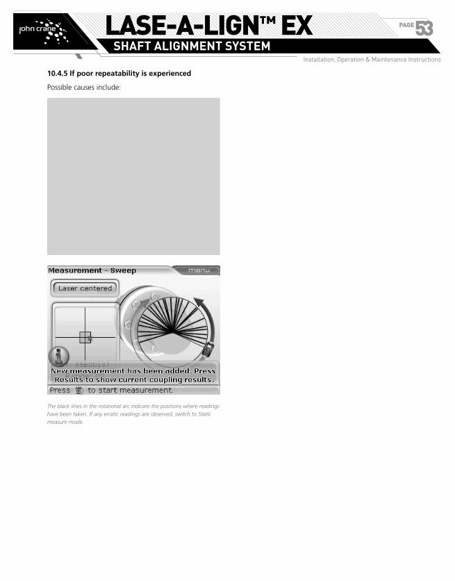
10.4.5 If poor repeatability is experienced
Possible causes include:
› Incorrect or loose bracket mounting
› Significant shaft play or coupling backlash
› Soft foot can cause positioning errors that make
repeat measurement necessary
› Loose anchor bolts
› Yellow knobs on transducer loose, or reflector
not locked
› Transducer is mounted incorrectly or upside
down
› Temperature changing: machines recently shut
down?
› Uneven shaft rotation
The black lines in the rotational arc indicate the positions where readings
have been taken. If any erratic readings are observed, switch to Static
measure mode.
LASE-A-LIGN™ EXSHAFT ALIGNMENT SYSTEM
Installation, Operation & Maintenance Instructions
PAGE53
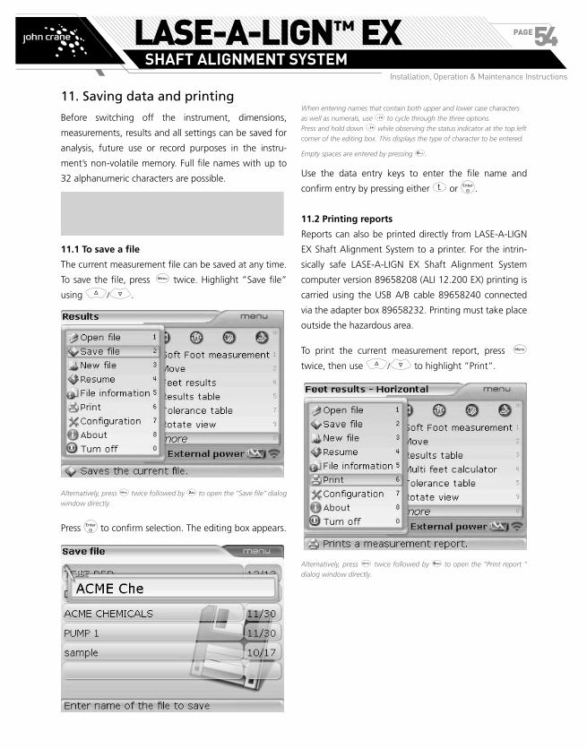
11. Saving data and printing
Before switching off the instrument, dimensions,
measurements, results and all settings can be saved for
analysis, future use or record purposes in the instru-
ment’s non-volatile memory. Full file names with up to
32 alphanumeric characters are possible.
NOTE: The length of the file name is limited de-
pending on the typeface used.
11.1 To save a file
The current measurement file can be saved at any time.
To save the file, press q twice. Highlight ”Save file”
using f/g.
Alternatively, press q twice followed by 2 to open the “Save file” dialog
window directly.
Press e to confirm selection. The editing box appears.
When entering names that contain both upper and lower case characters
as well as numerals, use o to cycle through the three options.
Press and hold down o while observing the status indicator at the top left
corner of the editing box. This displays the type of character to be entered.
Empty spaces are entered by pressing 0.
Use the data entry keys to enter the file name and
confirm entry by pressing either ß or e.
11.2 Printing reports
Reports can also be printed directly from LASE-A-LIGN
EX Shaft Alignment System to a printer. For the intrin-
sically safe LASE-A-LIGN EX Shaft Alignment System
computer version 89658208 (ALI 12.200 EX) printing is
carried using the USB A/B cable 89658240 connected
via the adapter box 89658232. Printing must take place
outside the hazardous area.
To print the current measurement report, press q
twice, then use f/g to highlight ”Print”.
Alternatively, press q twice followed by 6 to open the “Print report ”
dialog window directly.
LASE-A-LIGN™ EXSHAFT ALIGNMENT SYSTEM
Installation, Operation & Maintenance Instructions
PAGE54

Adapter box 89658232
USB A/B cable 89658240
connected to a printer
Intrinsically safe LASE-A-LIGN EX
Shaft Alignment System computer
89658208 (ALI 12.200 EX) Adapter box cable
Press e to confirm selection. The “Print report” screen
appears.
In this example the configured printer is PDF file. If another office printer
was configured, then the option ‘Change printer to PDF file’ would also
be displayed.
LASE-A-LIGN EX Shaft Alignment System provides the
option of printing reports in three different formats. Use
f/g to highlight the desired format and then
press e to print the selected report.
11.3 Configuring printer
If unable to print the measurement report, the printer
settings must be verified. This can be carried out from
the “Print report” screen. Press q and use either
f/g to highlight “Printer configuration”.
Alternatively, with context menu displayed, press 3 to access printer
configuration directly.
Press e to confirm selection. The “Printer configura-
tion” screen appears and the printing settings are made.
Alternatively, the “Printer configuration” screen can be
accessed at any time as described in Configuration and
data management.
LASE-A-LIGN™ EXSHAFT ALIGNMENT SYSTEM
Installation, Operation & Maintenance Instructions
PAGE55
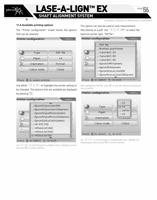
11.4 Available printing options
The “Printer configuration” screen shows the options
that can be selected.
Use either f/g to highlight the printer setting to
be changed. The options that are available are displayed
by pressing e.
Use f/g to scroll through the available printers. Highlight a printer
and press e to confirm selection.
This option can also be used to save measurement
files directly as a pdf. Use f/g/0 to select the
topmost printer type “Pdf file”.
After highlighting “Pdf file” press e to save the selected measurement
file as a pdf file.
Use f/g to scroll through the available paper sizes. Highlight the
required paper size and press e to confirm selection.
LASE-A-LIGN™ EXSHAFT ALIGNMENT SYSTEM
Installation, Operation & Maintenance Instructions
PAGE56

Use f/g to change the page orientation between “Portrait” for a
vertical layout and “Landscape” for a horizontal layout. Confirm selection
by pressing e.
Use f/g to select the color in which the report will be printed.
Selecting “Color” results in full color reports, while “Gray scale” results in
black and white reports.
LASE-A-LIGN™ EXSHAFT ALIGNMENT SYSTEM
Installation, Operation & Maintenance Instructions
PAGE57

Quick check measurement
At some point, it may be necessary to check the alignment
of a machine set that has been running long enough to
reach its ‘steady state’ (‘hot’) operating condition. In
that case, LASE-A-LIGN EX Shaft Alignment System can
be used to take quick alignment readings in a matter
of a few minutes after the machines are shut off. The
following procedure saves time by allowing you to begin
measurement immediately after switching on LASE-A-
LIGN EX Shaft Alignment System, i.e. without entering
machine dimensions first. Measurement is possible only
in the continuous sweep measurement mode.
1. As soon as the shafts have stopped rotating, lock
out machines and observe all safety precautions,
then mount the components, and connect the
transducer to LASE-A-LIGN EX Shaft Alignment
System as described in “Getting started” (page
24). If using the wireless data transmission module
89658259 (ALI 4.621 EX), please refer to “Laser
beam adjustment” on page 42.
2. Switch LASE-A-LIGN EX Shaft Alignment System on
and press m. If the laser beam has been centered
on the detector, turn the shafts in their normal
direction of operation by at least 60°.
Intrinsically safe EX Bluetooth module 89658259 (ALI 4.621 EX) is
available for use with the intrinsically safe LASE-A-LIGN EX Shaft
Alignment System transducer 89658230 (ALI 12.100 EX).
3. Press either e or k to finish measurement. The
‘Dimensions’ screen with missing dimensions opens.
4. Enter the required dimensions.
Missing dimensions are entered using the data entry keys and confirmed
by pressing e.
5. Once all dimensions have been entered, the results screen appears.
LASE-A-LIGN™ EXSHAFT ALIGNMENT SYSTEM
Installation, Operation & Maintenance Instructions
PAGE58

3. Press either e or k to finish measurement. The
‘Dimensions’ screen with missing dimensions opens.
4. Enter the required dimensions.
Missing dimensions are entered using the data entry keys and confirmed
by pressing e.
5. Once all dimensions have been entered, the results screen appears.
Soft foot
SOFT FOOT is the condition of machine frame distortion.
Any cause that results in machine frame distortion when
the machine is anchored to its foundation is a soft foot.
Some of the principal causes are:
› Non-coplanar machine mounting surfaces,
› Deformed machine frame or feet,
› External forces e.g. from connecting pipe or
bracket,
› Improper shimming or soiled machine feet.
› Too many shims under a machine foot (a
maximum of 3 should be used)
The consequences of forcibly tightening down the feet
are deformed machine frames, bent shafts and distorted
bearings. This leads to high vibration and premature failure.
Soft foot should be checked before aligning the shafts.
This can be done quickly and conveniently with the aid of
the instrument’s soft foot function. With the transducer
and reflector mounted on the shaft in the usual way, the
system is able to sense any machine movement when the
machine bolts are loosened individually. By entering the
machine dimensions, LASE-A-LIGN EX Shaft Alignment
System is able to calculate, from shaft movement, by how
much each foot has moved as it is loosened.
Once foot movements have been established, the results
are interpreted and translated into shim thicknesses to
be placed under the feet. How straightforward this is,
depends on the type of soft foot present.
Checking and correcting soft foot
conditions
The three main types are parallel soft foot, angular
soft foot, and induced soft foot. There are instances
where the soft foot is a combination of two or more
types. Checking for soft foot is part of machine and job
preparation.
NOTE: The machine(s) to be checked is/are as-
sumed to have four feet in an approximately
square formation. If the machine has six feet, it is
advisable to leave the middle feet loose and treat
the machine as a four-footed machine. Soft foot is
measured only on machine designated as movable.
Set up LASE-A-LIGN EX Shaft Alignment System in the
normal way as described in “Getting started” (page 24).
Rotate shafts to position the transducer and reflector at
either the 3:00 or 9:00 o’clock position.
Angular soft foot
The base of the foot is at an angle to its
foundation and they are only partly in contact.
In this case, suspect foot is checked with a feeler
gauge and corrected by building a custom ‘shim
wedge’ or machining the underside of the foot.
Parallel soft foot
One or more feet are too short or too long.
This usually results in the machine rocking on
the longer feet. This is corrected by shimming
the shorter feet.
The alignment results displayed depend on whether the shaft setting
‘All-in-one results’ has been activated. The screen opposite shows both
the coupling and feet results. Use k/f/g to cycle through the
different results views.
NOTE: If however, the option ‘All-in-one results’ has
not been activated in the ‘Shaft settings’ configura-
tion menu, only the sensor to coupling center dimen-
sion needs to be entered to display coupling results.
LASE-A-LIGN™ EXSHAFT ALIGNMENT SYSTEM
Installation, Operation & Maintenance Instructions
PAGE59

Enter machine dimensions and then press q. With
the context menu displayed, press 3 to access “Soft
foot” screen. Alternatively, access the screen by using
the navigation keys to highlight s, then pressing e
to confirm selection.
If initially the laser beam has not been centered, the
following screen appears.
Use the on-screen instructions to adjust the laser beam,
or refer to ‘Laser beam adjustment’ on page 42.
The on-screen instructions may also be prompted from
the ‘Soft foot’ screen by pressing q followed by 1.
Alternatively, use either f/g to highlight “Adjust
prism to laser”, then press e to confirm selection.
Follow the on-screen instructions to center the laser
beam.
After centering the laser beam, press either ß or e
and proceed with soft foot measurement.
NOTE: If however, the laser beam had already been
centered during set-up, the screen below appears.
LASE-A-LIGN™ EXSHAFT ALIGNMENT SYSTEM
Installation, Operation & Maintenance Instructions
PAGE60
NOTE: If however, either of the two significant ma-
chine dimensions, “front foot-to-back foot” and
“transducer-to-reflector”, are missing, the follow-
ing hint appears.
Use f/g to highlight ‘Yes’, confirming selection by pressing e. The
dimensions screen opens, and missing values may be entered.
If the shafts slip away from the 3:00 or 9:00 o’clock
position, an angle correction hint appears as shown
below.
Rotate the shafts back into the green sector (light
colored) and resume measurement.
When the message “angle in range” appears, you may either press e to
continue with soft foot measurement or wait for the process to resume
automatically.
Use the navigation keys to select the foot to be
measured. Press e to confirm foot selection. Loosen
the corresponding anchor bolt.
The calculated distance that the foot has risen is shown
on the screen. Press e to store the value and retain
it in the display. Re-tighten the bolt. The next foot is
highlighted automatically, or any desired foot can be
selected using the navigation keys.
Repeat this procedure for each foot. Cycle through
using the navigation keys.
LASE-A-LIGN™ EXSHAFT ALIGNMENT SYSTEM
Installation, Operation & Maintenance Instructions
PAGE61
The set soft foot tolerance is 0.06 mm (0.002”). The Tick indicates that
the measured soft foot is within tolerance and shimming corrections are
not necessary.
With the four foot values, the shimming corrections
can be determined. Note that these values are saved in
the file along with the dimensions, measurement and
results, and appear in the printed report.
Parallel soft foot correction
If two diagonal values are roughly equal and signifi-
cantly higher than the other two, parallel soft foot can
be assumed as a first solution.
Angular soft foot correction
If one value is significantly higher than the others, then
angular soft foot can be suspected.
The ‘problem foot’ or machine frame is probably bent
or distorted in some way. In this case loosen the bolt
and examine the foot more closely. Use a feeler gauge
to establish the variation of the gap and use these
measurements to sketch the shape and dimensions for
a ‘stair stepped shim wedge’.
If the soft foot is purely ‘angular’ then the stepped shim
will vary in thickness from about zero to twice the value
displayed by LASE-A-LIGN EX Shaft Alignment System.
Parallel soft footThe machine is rocking on two diagonal feet which are
longer than the other two. In this example, the correction
would be to place a 0.89mm shim under foot ‘b‘ (the foot
with the largest gap)
Angular soft footThe base of one or more feet is at an angle to
the foundation and is only partly in contact.
LASE-A-LIGN™ EXSHAFT ALIGNMENT SYSTEM
Installation, Operation & Maintenance Instructions
PAGE62

Checking pipe strain
The effects of pipe strain on shaft alignment can be
measured using LASE-A-LIGN EX Shaft Alignment
System. This feature is used to check for strain from
external sources acting on machines. The measured
values are quantified in terms of offset and angularity.
The values are combined for both the vertical and
horizontal directions. This check can prove the existence
of pipe strain on a pump or conduit strain on a motor.
An external stress on a machine frame usually results in
machine frame distortion. It is important to ascertain its
existence and eliminate it. This check complements but
does not replace the soft foot function.
How the function works
After mounting the transducer and prism as usual, turn
LASE-A-LIGN EX Shaft Alignment System on. Enter all
necessary machine dimensions as usual. Press m to
access the measurement screen. With the measurement
screen displayed, press q. The context menu with the
function ‘Pipe strain wizard’ (9) appears.
Alternatively, start the wizard by using f/g to highlight “Pipe Strain
Wizard”, confirming selection by pressing e.
Press 9 to start the pipe strain wizard.
The wizard opens always with the ‘Next’ button highlighted. Should this
not be the case, use the navigation keys to highlight ‘Next’. The wizard
may be exited by highlighting the ‘Exit’ button and confirming selection
by pressing e.
With the ‘Next’ button highlighted, press e to
proceed.
NOTE: If the components have not yet been mount-
ed, ensure that they are properly mounted and the
transducer is connected to the LASE-A-LIGN EX
Shaft Alignment System computer. You may refer
to the capital “Getting started” on page 42.
With the ‘Next’ button highlighted, press e to proceed
with measurement. The measurement screen appears.
LASE-A-LIGN™ EXSHAFT ALIGNMENT SYSTEM
Installation, Operation & Maintenance Instructions
PAGE63

If the laser beam is not centered, press q followed by 2 to proceed
with laser beam adjustment. Alternatively use f/g to highlight
the context menu item “Adjust prism to laser”, confirming selection by
pressing e.
Rotate the shafts over a wide enough measurement
range. When a wide enough measurement range is
attained, the “Stop” button appears.
With the “Stop” button highlighted, press e to finish
the first measurement. The instruction to loosen pipe
flange bolts then appears.
After loosening the pipe flange bolts, press e with the
‘Next’ button highlighted. This prompts the start of the
second measurement step.
Proceed to take measurements as described in first
measurement steps previously.
LASE-A-LIGN™ EXSHAFT ALIGNMENT SYSTEM
Installation, Operation & Maintenance Instructions
PAGE64

Pipe strain results are automatically displayed after
pressing e with the “Stop” button highlighted.
Toggle between ‘Finish’ and ‘Print’ using the navigation keys. Confirm
required option by pressing e.
The pipe strain measurement is documented in the file
measurement report and may also be saved as an indi-
vidual pipe strain measurement report PDF file or printed
directly from the LASE-A-LIGN EX Shaft Alignment
System computer. To save or print report, refer to the
section “Saving data and printing” on page 54.
NOTE: The measurement procedure and wizard
instructions are dependent on the measurement
mode used. In all instances, a wide enough mea-
surement range has to be attained.
LASE-A-LIGN™ EXSHAFT ALIGNMENT SYSTEM
Installation, Operation & Maintenance Instructions
PAGE65

Alignment options
Measurement modesIn addition to the standard ‘continuous sweep mode’,
LASE-A-LIGN EX Shaft Alignment System also offers
Static (0369) measurement modes.
The measurement modes are accessed via the mea-
surement screen. Press m to access the measurement
screen. While in the measurement screen, press q.
Use the navigation keys to select “Measurement
mode”/”Static”. The choice depends on the measure-
ment mode required.
Static measurement
This measurement mode is used for uncoupled shafts,
nonrotatable shafts and vertical foot-mounted or
flange-mounted machines.
After centering the laser beam as described in “Laser
beam adjustment” on page 42, turn the shafts to any
of the eight 45° positions (i.e. 12.00, 1.30, 3.00, 4.30,
6.00, 7.30, 9.00 or 10.30 o’clock position viewed from
coupling towards transducer). Position shaft as accu-
rately as possible using either an external inclinometer,
spirit level or protractor.
Use the navigation keys to position the clock hour hand
to the corresponding shaft position.
Pressing the navigation keys positions the clock hour hand at the next
45° position.
Press e to take the first measurement point. After
point is taken, rotate shafts to the next measurement
position. Ensure shafts are accurately placed at the 45°
position. Use the navigation keys to move the clock hour
hand on the display screen to the corresponding shaft
position. Take next measurement point by pressing e.
NOTE: If shaft rotation restrictions hinder the tak-
ing of measurement at particular shaft positions,
bypass these using the navigation keys.
Measurements must be taken in at least three positions
over 90°, but it is recommended to take more measure-
ments over a wider angle.
LASE-A-LIGN™ EXSHAFT ALIGNMENT SYSTEM
Installation, Operation & Maintenance Instructions
PAGE66

Use the navigation keys to position the clock hour hand
to the corresponding shaft position.
Pressing the navigation keys positions the clock hour hand at the next
45° position.
Press e to take the first measurement point. After
point is taken, rotate shafts to the next measurement
position. Ensure shafts are accurately placed at the 45°
position. Use the navigation keys to move the clock hour
hand on the display screen to the corresponding shaft
position. Take next measurement point by pressing e.
NOTE: If shaft rotation restrictions hinder the tak-
ing of measurement at particular shaft positions,
bypass these using the navigation keys.
Measurements must be taken in at least three positions
over 90°, but it is recommended to take more measure-
ments over a wider angle.
After finishing measurement, press k to display results.
Extending the measurement range
Gross misalignment of shafts or small angular misalign-
ment over large distances can cause the laser beam to
miss the detector surface during measurement. When
this happens, ‘Laser End’ appears on the display screen
and the instrument’s ‘extend’ function can be used.
1. When measuring and ‘Laser End’ message appears,
rotate the shafts backwards until the laser beam
re-enters the measurement range. The message
‘Laser OK’ reappears on the display. Press q to
access the ‘extend’ option. Use f/g to
highlight “InfiniRange”.
Alternatively, access the InfiniRange screen directly by pressing 2 with
the context menu displayed.
2. Press e to confirm selection. The program
interrupts measurement and switches to the beam
adjustment screen. The current beam position is
automatically recorded and taken as the starting
point for range extension.
CAUTION! Do not allow shafts to turn during this process.
3. Readjust the beam into the target square using the
yellow reflector knob and the metal thumb-wheel.
4. On centering the laser dot, the blue LASE-A-LIGN
EX Shaft Alignment System LED lights up. Press
e. The adjusted beam position is automatically
recorded and taken as the end point of the read-
justment.
LASE-A-LIGN™ EXSHAFT ALIGNMENT SYSTEM
Installation, Operation & Maintenance Instructions
PAGE67

5. Continue measurement as before, rotating the
shafts and pressing e to take measurements at
the desired positions.
The program includes the displacement of beam read-
justment in its alignment calculations.
NOTE: The ‘extend’ option is available in ‘static’
measurement modes.
‘Laser END’ is displayed when the reflected beam
misses the detector. This situation occurs when ma-
chines are severely misaligned, or when the beam
travel is long. Measurement is not taken when this
message appears.
Remeasuring
The possibility to remeasure is provided in all measure-
ment modes. To remeasure, the current measurement
needs to be stopped. To stop a measurement, press q
while carrying out measurement. Use f/g to
highlight “Stop”.
Alternatively, stop measurement by pressing 3 with the context menu displayed.
Confirm selection by pressing e.
To start a new measurement, press q and use
f/g to highlight “Start”.
Start measurement directly by pressing 4.
A different measurement mode can also be selected
under “Measurement mode” before starting to
remeasure.
Confirm selection by pressing e.
LASE-A-LIGN™ EXSHAFT ALIGNMENT SYSTEM
Installation, Operation & Maintenance Instructions
PAGE68

Resume
LASE-A-LIGN EX Shaft Alignment System provides the
possibility to turn off the instrument during measure-
ment and resume with the last file opened. On switching
the instrument on, the measurement file loaded is the
one that was last opened, provided it had already been
saved. If you prefer to open a completely new file, press q followed by 2.
This auto-resume function ensures that the measure-
ment file last selected, when the instrument switches
itself off due to the power management function
“power scheme” (see configuration on page 16),
remains the active file when the instrument is switched
on again.
Averaging
In certain industrial conditions, it may be necessary to
increase the number of measurements to be averaged
when taking readings to attain the desired accuracy.
Particular cases include applications with increased
machinery vibration. An increased averaging also
improves the accuracy when measuring sleeve bearings,
white metal bearings and journal bearings.
The number of individual readings which are averaged
together to form one measurement are set via the mea-
surement screen. Press q while in the measurement
screen. Use f/g to highlight “Averaging”.
Alternatively, access the averaging screen directly by pressing 6 while the context menu is displayed.
Confirm selection by pressing e.
The average setting can be changed from a minimum
averaging of 0.4 seconds to a maximum averaging of
1.6 seconds.
NOTE: Averaging is possible only in Static measure-
ment modes. The averaging setting that is selected
will also be active in soft foot and Move. Should
high averaging be selected, patience must be exer-
cised during Move to allow LASE-A-LIGN EX Shaft
Alignment System enough time to “catch-up”as the
machine is moved. In this case, each reading that
must be calculated to update the graphic display will
take a longer time. Averaging cannot be changed
once a measurement has been started.
LASE-A-LIGN™ EXSHAFT ALIGNMENT SYSTEM
Installation, Operation & Maintenance Instructions
PAGE69

XY View
Before measurement begins, the reflected laser beam
must be adjusted such that it strikes the detector
surface. The beam should strike the detector as close
to the center as possible. To facilitate adjustment, the
height of the transducer and the reflector should be
aligned and the brackets rotationally aligned.
The option “XY View” can be activated to help meet the
requirement mentioned above.
To access the “XY View”, press q while in the measure-
ment screen. Use f/g to highlight “XY View”.
Alternatively, access the XY view directly by pressing 5 while the context menu is displayed.
Confirm selection by pressing e. The “XY View”
table screen appears.
Displayed are the absolute X,Y coordinates of the laser beam on the
detector surface, the angle at which the transducer is currently positioned
on the shaft, the transducer serial number and firmware version.
Additional “XY View” capabilities include the setting
of the XY coordinates as a reference value. To access
this option, press q while in the “XY View” table
screen above. Use f/g to highlight “Relative
coordinates”.
Relative coordinates may be accessed directly pressing o while the
context menu is displayed.
Press e to set the current laser dot position as 0,0.
The adjusted beam position is set to ‘0,0‘ to serve as a reference. Press e
to toggle between the reference and the absolute values. This can also be
done via the “XY View” context menu.
LASE-A-LIGN™ EXSHAFT ALIGNMENT SYSTEM
Installation, Operation & Maintenance Instructions
PAGE70

If the laser beam dot is adjusted while in the “Relative
mode” screen, it traces a path showing the laser dot
movement.
The coordinates to the new laser dot position are ‘3.3, -0.5’.
LASE-A-LIGN™ EXSHAFT ALIGNMENT SYSTEM
Installation, Operation & Maintenance Instructions
PAGE71

Updating the LASE-A-LIGN EX Shaft Alignment System firmware
Updating LASE-A-LIGN EX Shaft Alignment
System to a newer version
� Actual LASE-A-LIGN EX Shaft Alignment
System firmware updates are carried out with
the use of the especially approved John Crane
memory stick (aka jump-drive).
� The necessary update may be downloaded
from the John Crane website.
� Old John Crane memory sticks must be
disposed of in accordance to the directive on
Waste Electrical and Electronic Equipment
(WEEE).
1. Transferring update files to the memory stick
If you are acquiring the update via the website, you
will require to transfer it to the approved memory stick
before commencing the upgrading.
2. Downloading the update from the John Crane
website
a) Go to the John Crane website and get the latest
LASE-A-LIGN EX Shaft Alignment System firmware
update.
Download the update to a folder on your PC. It is a
large file, this may take several minutes.
NOTE: DO NOT download directly to your ap-
proved memory stick! If you had previously carried
out an update using the memory stick, ensure that
you DELETE all old folders.
b) Connect the approved John Crane memory stick
with not less than 100 MB of free space to your
PC. Double-click the “LASE-A-LIGN EX-Shaft-
Firmware_1.2x.exe” file in your PC. You will be
prompted to extract the file to a memory stick.
The intrinsically safe computer 89658208 (ALI 12.200 EX) is updated only
via the adapter box 89658232 and only using the approved memory stick
89658237.
c) Select the location of your memory stick with
‘Browse’. Then click ‘Install’. The files extraction
process begins.
d) If the extraction has been successful, the update is
now on the memory stick, and you may proceed to
section 3 - ‘Carrying out the firmware update.
m
LASE-A-LIGN™ EXSHAFT ALIGNMENT SYSTEM
Installation, Operation & Maintenance Instructions
PAGE72

3. Carrying out the firmware update
Before starting the upgrade verify that your memory
stick has the files shown below in the ‘LASE-A-LIGN EX
Shaft Alignment System’ directory.
a) Press e to switch LASE-A-LIGN EX Shaft
Alignment System on. Wait for the dimensions
screen to appear. Press q to view the battery
capacity.
NOTE: Before proceeding with the update ensure
that the indicated nominal capacity of the battery
is greater than 50%. If this is not the case, replace
all six AA batteries at the same time.
� For the intrinsically safe version, the computer
may be mains powered via the adapter box
89658232 should the battery capacity fall
below 50%.
Please note that the following update procedure for
the intrinsically safe LASE-A-LIGN EX Shaft Align-
ment System computer. When carrying out firm-
ware update to the intrinsically safe LASE-A-LIGN
EX Shaft Alignment System computer 89658208
(ALI 12.200 EX) , is that the adapter box 89658232,
must be connected to the intrinsically safe LASE-
A-LIGN EX Shaft Alignment System computer.
� For the intrinsically safe version 89658208 (ALI
12.200 EX), connect the adapter box to the
computer which MUST remain switched off.
� For the intrinsically safe version 89658208 (ALI
12.200 EX) connect the approved John Crane
memory stick 89658237 to the adapter box directly
via the USB memory stick interface, then switch the
computer on.
b) A hint indicating the availability of a new firmware
and the need to reboot the LASE-A-LIGN EX Shaft
Alignment System computer appears.
a
LASE-A-LIGN™ EXSHAFT ALIGNMENT SYSTEM
Installation, Operation & Maintenance Instructions
PAGE73

c) When the hint above appears, press and hold down
e until the device reboots. The display goes dark.
d) The update process will start automatically after a
little while (as long as 10 seconds). You will hear a
few beeps and see flashing diodes as the process
begins.
NOTE: Do NOT turn off the device or remove the
memory stick during the entire update process,
which takes up to 10 minutes.
e) When the process is completed, the dimensions
screen appears. Press and hold enter key until the
devise resets
Your LASE-A-LIGN EX Shaft Alignment System is
now ready for use with the uploaded version.
4. Checking uploaded version
a) After the opening dimensions screen appears,
press q and use the navigation keys to select
“More”/”About”
Alternatively, after pressing q access the ‘Application info’ screen
directly using the shortcut numbers on the data entry keys. Pressing 0
followed by 8 opens the ‘Application info’ screen shown below.
LASE-A-LIGN™ EXSHAFT ALIGNMENT SYSTEM
Installation, Operation & Maintenance Instructions
PAGE74

b) Press e to confirm selection. The application
information screen shown below appears, with the
new firmware version listed under “Application
version”.
The application details include the uploaded firmware version, the
application build.
Transducer firmware updateIt is now possible to carry out a transducer firmware
update directly via the LASE-A-LIGN EX Shaft Alignment
System computer. If a transducer with an older firmware
version is connected to the LASE-A-LIGN EX Shaft
Alignment System computer, a hint indicating that the
transducer firmware requires updating appears on the
display.
Use f/g to select ‘Yes’/’No’ respectively. Confirm selection by
pressing e.
Use f/g to select whether or not to update the
transducer. If you select to update the transducer, press
e. The sensor firmware update wizard appears.
NOTE: The transducer must be connected to the
LASE-A-LIGN EX Shaft Alignment System computer
to perform this update.
The wizard guides the user through the transducer firmware update in
self-explanatory steps.
Alternatively, the transducer firmware update can
be carried out later by accessing “sensor firmware
upgrade” through the “XY View” screen.
The wizard is accessed by pressing m followed by q then by 4. This
opens the “XY View”. From the “XY View” screen press q and open the
wizard by pressing 5.
LASE-A-LIGN™ EXSHAFT ALIGNMENT SYSTEM
Installation, Operation & Maintenance Instructions
PAGE75

NOTE: It is strongly recommended that the
transducer firmware update be carried out. The
transducer firmware update takes about 10 – 15
minutes and should be carried out using the LASE-
A-LIGN EX Shaft Alignment System transducer ca-
ble 89658234. And therefore if your currently set
connection is via wireless EX Bluetooth module,
you must first access the “sensor selection” option
through the Measure screen’s context menu and
select and confirm the “Sensor @ Port 1 (RS-232)”
option instead.
Checking transducer firmware version
The firmware version of the transducer may be checked
at any time. To do this, proceed as follows.
a) Connect the transducer to the LASE-A-LIGN EX
Shaft Alignment System computer.
b) Press m to access the measurement screen. While
in the measurement screen, press q to display the
context menu.
c) With the context menu displayed, use f/g
to highlight “XY View”.
Alternatively, the XY View screen may be accessed directly by pressing 4
while the context menu is displayed.
d) Press e to confirm selection. The XY View screen
appears.
e) With the XY View screen displayed, press q
to display the context menu. Use f/g to
highlight the menu item “Sensor check”.
Direct sensor check may also be achieved by pressing 6 while the
context menu is displayed.
f) Press e to confirm selection.
g) If the transducer firmware version is up-to-date, the
screen below appears.
LASE-A-LIGN™ EXSHAFT ALIGNMENT SYSTEM
Installation, Operation & Maintenance Instructions
PAGE76
h) If however, the transducer firmware version is old,
the following screen appears.
LASE-A-LIGN™ EXSHAFT ALIGNMENT SYSTEM
Installation, Operation & Maintenance Instructions
PAGE77

This chapter deals with alignment of machines that
require use of special procedures rather than those
for the standard horizontal alignment. These special
applications include:
� Machine trains (groups of 3 machines coupled
together)
� Flanged machines (mounted vertically or horizon-
tally)
Machine train alignmentHow to align machinery trains
The following step-by-step approach is recommended
for 3-machine trains.
› a. Measure alignment at each coupling
› b. Display results and optimize corrections (by
defining ‘stationary’ machine feet)
› c. Align two machines (remount transducer and
reflector if necessary)
› d. Recheck alignment results
› e. Align the next machine in the train and repeat
alignment check
Machine train set-up
Machine train set-up resembles the set-up described on
page 24 and will therefore be outlined here only briefly.
› While in dimensions screen, use the navigation
keys to highlight either machine then press q.
The context menu with the menu item ‘Add last
machine’ appears.
› Use f/g to highlight “Add last machine”
and confirm selection by pressing e. The added
machine appears on the right end of the train.
Alternatively, press 5 with the dimensions context menu displayed [see
previous screen] to automatically add machine to the right end of the train
.
› Configure the machine train as appropriate.
The train elements appearing on the screen are shown highlighted on the
train icon on the top right of the display. Pressing horilong enough
moves the view of the train to the right or left respectively.
Special alignment applications
LASE-A-LIGN™ EXSHAFT ALIGNMENT SYSTEM
Installation, Operation & Maintenance Instructions
PAGE78

Use h/i to highlight machine to be edited. Pressing e reveals the
corresponding sub menu
Measurement
› Use h/i to select the coupling to be
measured. The transducer is to be mounted on
the machine shown on the left side in the screen
diagram.
› Remove the dust cap from the transducer and
switch it on. Leave the reflector dust cap on.
› Press m and adjust the beam onto the dust cap
(refer to section 7.3 ‘Laser beam adjustment’ on
page 42).
› Proceed to carry out measurement as described
in section 8 ‘Take measurements’ in the chapter
“Horizontal shaft alignment”, observing the re-
quirements for valid measurement – shafts must
be turned by at least 60°.
In this example, coupling 1 is measured using the continuous sweep
mode. Measurement is stopped by pressing q followed by 3 when
the context menu appears
› Press e to stop measurement.
Pressing 3 when the context menu appears stops measurement.
› Mount the transducer and reflector across the
next coupling.
› Press h/i long enough to select the next
coupling.
In this example, coupling 2 is measured using the continuous sweep
measurement mode. In this case, measurement is stopped by pressing e . Alternatively, press q followed by 3 when the context menu appears
› Repeat the measurement procedure as described
previously.
LASE-A-LIGN™ EXSHAFT ALIGNMENT SYSTEM
Installation, Operation & Maintenance Instructions
PAGE79
Evaluating results
Press k to view the alignment results at the individual
couplings. Cycle through all available results screens
using f/g/ k.
Horizontal and vertical feet and coupling values for machines B and C.
Pressing i/htoggles between coupling 1 [machines A and B] and
coupling 2 [B and C]
Horizontal feet and coupling values at the coupling position between
machines B and C
Vertical feet and coupling values at the coupling position between
machines B and C
The entire machine train overview is part of the results loop and is
displayed by cycling through the loop using k,f,g. This screen
shows the overview with vertical feet and coupling values between
machines B and C.
Entire machine train overview with horizontal feet and coupling values
between machines B and C
LASE-A-LIGN™ EXSHAFT ALIGNMENT SYSTEM
Installation, Operation & Maintenance Instructions
PAGE80
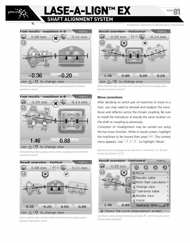
Vertical feet and coupling values at the coupling position between
machines A and B
Horizontal feet and coupling values at the coupling position between
machines A and B
Entire machine train overview with vertical feet and coupling values
between machines A and B
Entire machine train overview with horizontal feet and coupling values
between machines A and B
Move corrections
After deciding on which pair of machines to move in a
train, you may need to reinstall and readjust the trans-
ducer and reflector across the chosen coupling. Be sure
to install the transducer at exactly the same location on
the shaft or coupling as previously.
Correction of misalignment may be carried out using
the live move function. While in results screen, highlight
the machines to be moved then press q. The context
menu appears. Use f/g to highlight ‘Move’.
Machine pair to be moved can be selected in “Dimensions” or “Results”
screens by pressing h/i.
Live Move is also accessed directly by pressing 1 with the results screen
context menu displayed.
LASE-A-LIGN™ EXSHAFT ALIGNMENT SYSTEM
Installation, Operation & Maintenance Instructions
PAGE81

Confirm selection by pressing e. A Press 1 to access
‘Move’. A hint appears on the display requesting
selection of direction of the move.
Use f/g to highlight the direction to move the
machine and confirm selection by pressing e. The
window used to position the transducer and reflector in
the appropriate 45° position appears.
Rotate the shaft to position the transducer and reflector
in any one of the four 45° positions indicated by the
green sectors (light colored). If the laser beam has been
centered, and either machine is designated stationary,
Live Move starts automatically.
If the laser beam has not been centered, the laser adjustment guide
appears on the screen. Use it to center the laser beam
If however, the pair of machines selected are both desig-
nated movable, then a hint appears on the display request-
ing the designation of only one machine as movable.
Use f/g to highlight the machine to be moved,
then press e to confirm selection. The hint requesting
selection of the direction of the move appears.
LASE-A-LIGN™ EXSHAFT ALIGNMENT SYSTEM
Installation, Operation & Maintenance Instructions
PAGE82
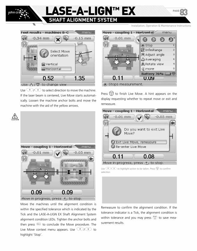
Use f/g to select direction to move the machine.
If the laser beam is centered, Live Move starts automat-
ically. Loosen the machine anchor bolts and move the
machine with the aid of the yellow arrows.
Do NOT attempt to move the machine using heavy
sledgehammer blows. This can cause bearing dam-
age, and also produce inaccurate MOVE results.
Jack bolts on the feet or other mechanical or hy-
draulic devices are recommended for moving ma-
chines.
Move the machines until the alignment condition is
within the specified tolerance which is indicated by the
Tick and the LASE-A-LIGN EX Shaft Alignment System
alignment condition LEDs. Tighten the anchor bolts and
then press q to conclude the Move procedure. The
Live Move context menu appears. Use f/g to
highlight ‘Stop’.
Press to finish Live Move. A hint appears on the
display requesting whether to repeat move or exit and
remeasure.
Use f/g to highlight action to be taken. Press e to confirm
selection.
NOTE: As the true position of shaft rotation axes
can only be determined by rotating shaft during
measurement, it is not possible to exit live move
without carrying out another measurement.
Remeasure to confirm the alignment condition. If the
tolerance indicator is a Tick, the alignment condition is
within tolerance and you may press e to save mea-
surement results.
LASE-A-LIGN™ EXSHAFT ALIGNMENT SYSTEM
Installation, Operation & Maintenance Instructions
PAGE83
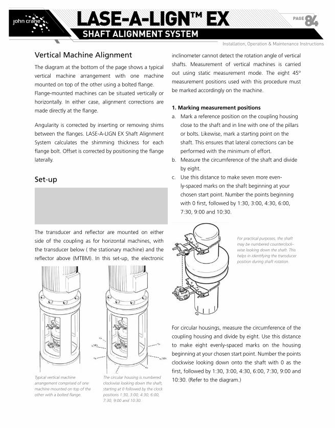
Vertical Machine Alignment
The diagram at the bottom of the page shows a typical
vertical machine arrangement with one machine
mounted on top of the other using a bolted flange.
Flange-mounted machines can be situated vertically or
horizontally. In either case, alignment corrections are
made directly at the flange.
Angularity is corrected by inserting or removing shims
between the flanges. LASE-A-LIGN EX Shaft Alignment
System calculates the shimming thickness for each
flange bolt. Offset is corrected by positioning the flange
laterally.
Set-up
NOTE: Before commencing with this section,
please acquaint yourself with the chapter ‘Horizon-
tal machine alignment’ starting page 27.
The transducer and reflector are mounted on either
side of the coupling as for horizontal machines, with
the transducer below ( the stationary machine) and the
reflector above (MTBM). In this set-up, the electronic
inclinometer cannot detect the rotation angle of vertical
shafts. Measurement of vertical machines is carried
out using static measurement mode. The eight 45°
measurement positions used with this procedure must
be marked accordingly on the machine.
1. Marking measurement positions
a. Mark a reference position on the coupling housing
close to the shaft and in line with one of the pillars
or bolts. Likewise, mark a starting point on the
shaft. This ensures that lateral corrections can be
performed with the minimum of effort.
b. Measure the circumference of the shaft and divide
by eight.
c. Use this distance to make seven more even-
ly-spaced marks on the shaft beginning at your
chosen start point. Number the points beginning
with 0 first, followed by 1:30, 3:00, 4:30, 6:00,
7:30, 9:00 and 10:30.
For practical purposes, the shaft
may be numbered counterclock-
wise looking down the shaft. This
helps in identifying the transducer
position during shaft rotation.
For circular housings, measure the circumference of the
coupling housing and divide by eight. Use this distance
to make eight evenly-spaced marks on the housing
beginning at your chosen start point. Number the points
clockwise looking down onto the shaft with 0 as the
first, followed by 1:30, 3:00, 4:30, 6:00, 7:30, 9:00 and
10:30. (Refer to the diagram.)Typical vertical machine
arrangement comprised of one
machine mounted on top of the
other with a bolted flange.
The circular housing is numbered
clockwise looking down the shaft,
starting at 0 followed by the clock
positions 1:30, 3:00, 4:30, 6:00,
7:30, 9:00 and 10:30.
2. Mounting components and selecting machine
orientation
a. Mount the transducer and reflector on either side
of the coupling, ensuring that they are aligned
exactly with the 0 or reference mark.
b. If using the RS232 interface to collect measurement
data, connect the transducer to LASE-A-LIGN
EX Shaft Alignment System and switch on the
instrument. If using the wireless data transmission
EX Bluetooth module 89658259 (ALI 4.621 EX),
simply switch on the instrument.
c. From the dimension screen that appears, press
q. With the context menu displayed, use the
navigation keys to highlight ‘Train orientation’ >
‘Vertical train’.
Alternatively, with the context menu displayed, select vertical train
orientation directly by pressing 7 then 2. A hint requiring confirma-
tion to the selected train orientation appears.
d. Confirm selected train orientation by pressing e.
A hint appears requiring the acknowledgment of
the change. Press e to acknowledge.
3. Editing flange configuration
A typical vertical machine train arrangement consists of
machines mounted together using a bolted flange. To
configure the flange proceed as follows:
a. Proceeding from 2 above, and with MTBM
highlighted press e then use g to highlight
“Change to flange”.
LASE-A-LIGN™ EXSHAFT ALIGNMENT SYSTEM
Installation, Operation & Maintenance Instructions
PAGE84

2. Mounting components and selecting machine
orientation
a. Mount the transducer and reflector on either side
of the coupling, ensuring that they are aligned
exactly with the 0 or reference mark.
b. If using the RS232 interface to collect measurement
data, connect the transducer to LASE-A-LIGN
EX Shaft Alignment System and switch on the
instrument. If using the wireless data transmission
EX Bluetooth module 89658259 (ALI 4.621 EX),
simply switch on the instrument.
c. From the dimension screen that appears, press
q. With the context menu displayed, use the
navigation keys to highlight ‘Train orientation’ >
‘Vertical train’.
Alternatively, with the context menu displayed, select vertical train
orientation directly by pressing 7 then 2. A hint requiring confirma-
tion to the selected train orientation appears.
d. Confirm selected train orientation by pressing e.
A hint appears requiring the acknowledgment of
the change. Press e to acknowledge.
3. Editing flange configuration
A typical vertical machine train arrangement consists of
machines mounted together using a bolted flange. To
configure the flange proceed as follows:
a. Proceeding from 2 above, and with MTBM
highlighted press e then use g to highlight
“Change to flange”.
Alternatively, press 3 with the menu items displayed.
b. Confirm selection by pressing e . The “Edit
flange” screen appears.
The parameters that can be edited are number of bolts, outer flange
and bolt circle diameters. These parameters are highlighted using the
navigation keys, and edited directly using the data entry keys.
c. To edit the flange pattern, press q while in the
‘Flange edit’ screen.
The following flange patterns are available:
› Circular flange
› Square flange
› Square flange - circular bolt pattern
d. Press 3 to access the flange configuration sub
menu items.
LASE-A-LIGN™ EXSHAFT ALIGNMENT SYSTEM
Installation, Operation & Maintenance Instructions
PAGE85
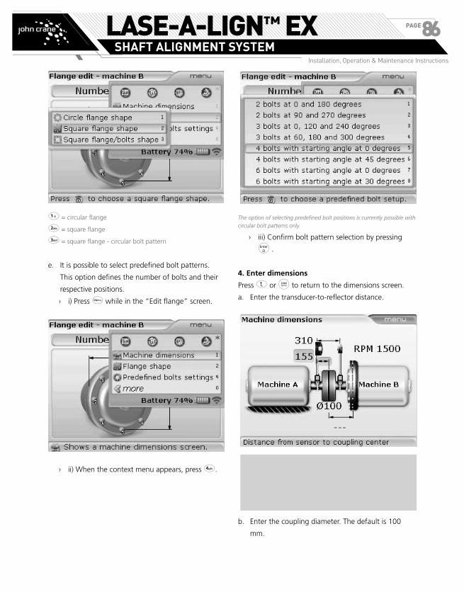
1 = circular flange
2 = square flange
3 = square flange - circular bolt pattern
e. It is possible to select predefined bolt patterns.
This option defines the number of bolts and their
respective positions.
› i) Press q while in the “Edit flange” screen.
› ii) When the context menu appears, press 4.
The option of selecting predefined bolt positions is currently possible with
circular bolt patterns only.
› iii) Confirm bolt pattern selection by pressing
e .
4. Enter dimensions
Press ß or d to return to the dimensions screen.
a. Enter the transducer-to-reflector distance.
NOTE: The transducer-to-coupling center distance
is calculated as half the transducer-to-reflector dis-
tance automatically. Should need be, this value can
be edited directly using the data entry keys.
b. Enter the coupling diameter. The default is 100
mm.
LASE-A-LIGN™ EXSHAFT ALIGNMENT SYSTEM
Installation, Operation & Maintenance Instructions
PAGE86

c. Enter the coupling center-to-flange distance.
d. Enter the RPM. The default is 1500. (1800 if units
option is set to US units.)
NOTE: The flange configuration can also be edited
from the above screen by highlighting the flanged
machine then pressing e.
To edit the flange configuration, use g to highlight ‘Edit flange’ then
confirm selection by pressing e. Alternatively press 5 with the context
menu displayed. The “Edit flange” screen described in 3 previously
appears.
Measurements can now be made. If using the wireless
EX bluetooth module, ensure it is switched on.
5. Measure using Static Measurement mode
a. Press m and then center the laser beam.
b. Rotate the shafts to the first measurement position.
The reference mark and the measurement position
0 must be aligned with each other. Use the
navigation keys to place the screen hour hand to
correspond with the position of the reflector and
transducer on the shafts.
LASE-A-LIGN™ EXSHAFT ALIGNMENT SYSTEM
Installation, Operation & Maintenance Instructions
PAGE87

c. Press e to take the first measurement point.
d. Rotate the shafts to the second measurement
position (e.g. 1:30). Move the screen hour hand
using the navigation keys to correspond with the
new position of the reflector and transducer on the
shafts. Press e to take measurement point.
NOTE: A minimum of three measurement posi-
tions are required to obtain results, but it is recom-
mended that a maximum number of measurement
points be taken to improve the quality of results.
6. Results
When measurement is complete, press w to view
results.
The ‘all-in-one’ results screen shows the coupling gap and offset values
in the 0-6 and 3-9 directions for short flex coupling and the flange
correction values.
NOTE: Sign convention (for vertical machines)
POSITIVE GAP opens towards 0:00 or 3:00
POSITIVE OFFSET if the top coupling half is offset
towards 0:00 or 3:00
Cycle through the coupling results and the flange cor-
rection positions using either k, f or g.
In this example, the Cross tolerance indicator indicates that the flange
needs to be adjusted in the 0-6 direction.
In this example, the Cross tolerance indicator indicates that the flange
needs to be adjusted in the 3-9 direction.
Shimming corrections are accessed by pressing q
while in the “Feet results” screen. Use g to highlight
the context menu item ‘Flange corrections’.
LASE-A-LIGN™ EXSHAFT ALIGNMENT SYSTEM
Installation, Operation & Maintenance Instructions
PAGE88
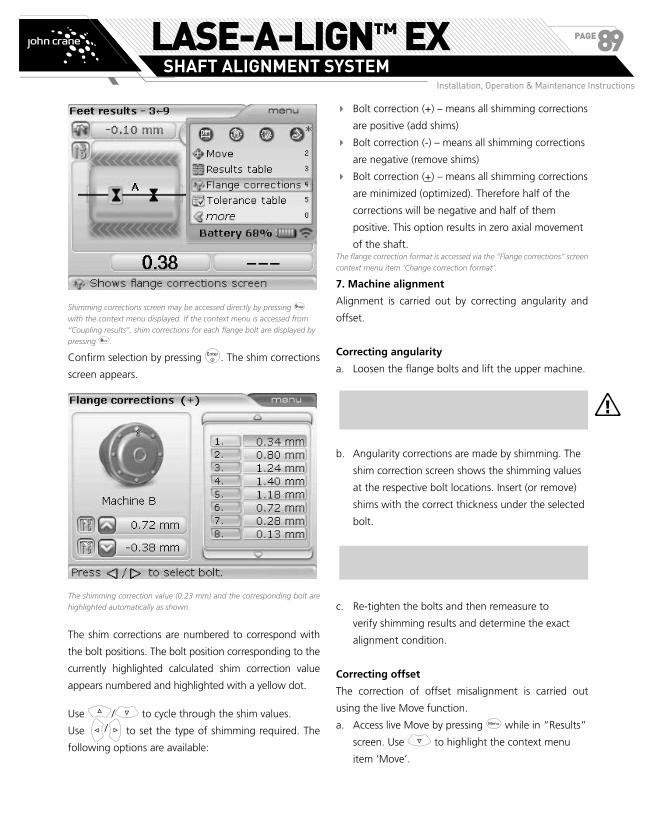
Shimming corrections screen may be accessed directly by pressing 9
with the context menu displayed. If the context menu is accessed from
“Coupling results”, shim corrections for each flange bolt are displayed by
pressing 8.
Confirm selection by pressing e. The shim corrections
screen appears.
The shimming correction value (0.23 mm) and the corresponding bolt are
highlighted automatically as shown.
The shim corrections are numbered to correspond with
the bolt positions. The bolt position corresponding to the
currently highlighted calculated shim correction value
appears numbered and highlighted with a yellow dot.
Use f/g to cycle through the shim values.
Use h/i to set the type of shimming required. The
following options are available:
� Bolt correction (+) – means all shimming corrections
are positive (add shims)
� Bolt correction (-) – means all shimming corrections
are negative (remove shims)
� Bolt correction (+) – means all shimming corrections
are minimized (optimized). Therefore half of the
corrections will be negative and half of them
positive. This option results in zero axial movement
of the shaft.The flange correction format is accessed via the “Flange corrections” screen
context menu item ‘Change correction format’.
7. Machine alignment
Alignment is carried out by correcting angularity and
offset.
Correcting angularity
a. Loosen the flange bolts and lift the upper machine.
The machine bolts must be undamaged and re-
movable.
b. Angularity corrections are made by shimming. The
shim correction screen shows the shimming values
at the respective bolt locations. Insert (or remove)
shims with the correct thickness under the selected
bolt.
NOTE: Use good quality shims which can be sup-
plied by John Crane
c. Re-tighten the bolts and then remeasure to
verify shimming results and determine the exact
alignment condition.
Correcting offset
The correction of offset misalignment is carried out
using the live Move function.
a. Access live Move by pressing q while in “Results”
screen. Use g to highlight the context menu
item ‘Move’.
a
LASE-A-LIGN™ EXSHAFT ALIGNMENT SYSTEM
Installation, Operation & Maintenance Instructions
PAGE89
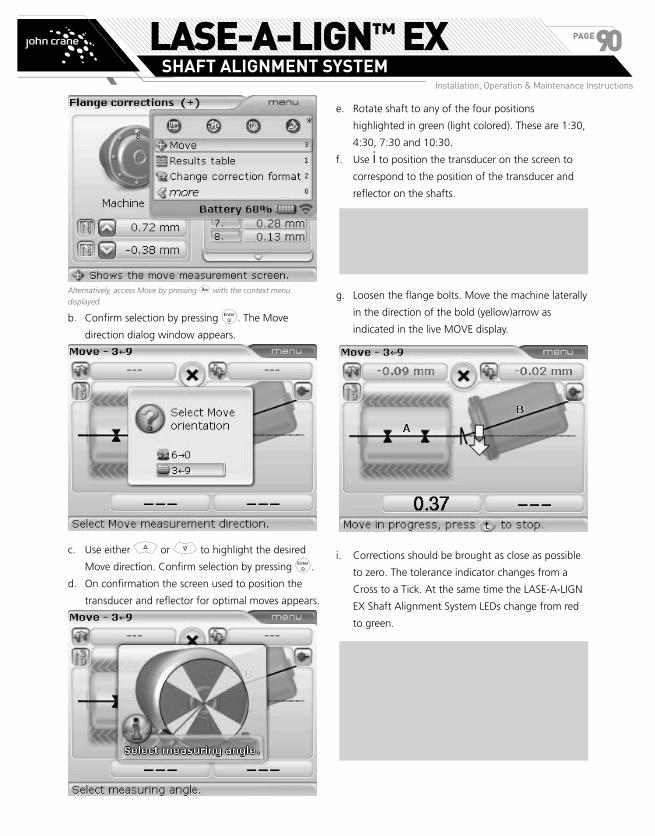
Alternatively, access Move by pressing 3 with the context menu
displayed.
b. Confirm selection by pressing e. The Move
direction dialog window appears.
c. Use either f or g to highlight the desired
Move direction. Confirm selection by pressing e.
d. On confirmation the screen used to position the
transducer and reflector for optimal moves appears.
e. Rotate shaft to any of the four positions
highlighted in green (light colored). These are 1:30,
4:30, 7:30 and 10:30.
f. Use i to position the transducer on the screen to
correspond to the position of the transducer and
reflector on the shafts.
NOTE: If the laser beam is centered, Live MOVE
starts automatically. If beam is not centered, a hint
to center the laser beam appears on the display.
g. Loosen the flange bolts. Move the machine laterally
in the direction of the bold (yellow)arrow as
indicated in the live MOVE display.
i. Corrections should be brought as close as possible
to zero. The tolerance indicator changes from a
Cross to a Tick. At the same time the LASE-A-LIGN
EX Shaft Alignment System LEDs change from red
to green.
NOTE: Use appropriate tools (e.g. levers) to posi-
tion the machine. Take care not to let the shims slip
out of place during lateral positioning. When ma-
chine is correctly positioned, tighten the bolts back
down. Remeasure to check if the new alignment
condition is within tolerance.
LASE-A-LIGN™ EXSHAFT ALIGNMENT SYSTEM
Installation, Operation & Maintenance Instructions
PAGE90

Appendix
Suggested shaft alignment tolerances
RPM Metric(mm)
Inch(mils)
Soft Foot Any 0.06 2.0
Acceptable Acceptable
Short Flexible coupling
600 9.0
750 0.19
1500 0.09
1800 3.0
3000 0.06
3600 1.5
6000 0.03
7200 1.0
Angularity(coupling gap difference
per 100mm or 10" diameter)
600 15.0
750 0.13
1500 0.07
1800 5.0
3000 0.04
3600 3.0
6000 0.03
7200 2.0
LASE-A-LIGN™ EXSHAFT ALIGNMENT SYSTEM
Installation, Operation & Maintenance Instructions
PAGE91
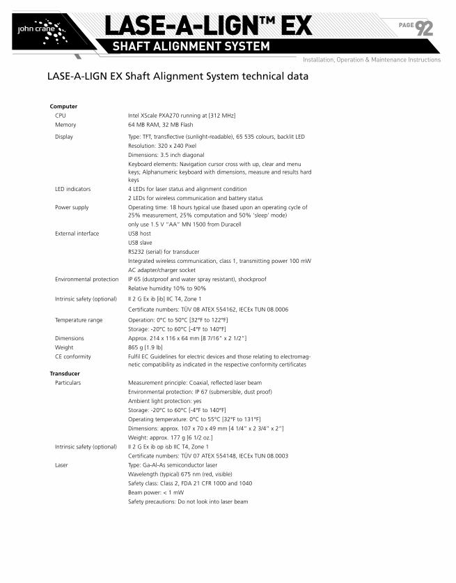
LASE-A-LIGN EX Shaft Alignment System technical data
Computer
CPU Intel XScale PXA270 running at [312 MHz]
Memory 64 MB RAM, 32 MB Flash
Display Type: TFT, transflective (sunlight-readable), 65 535 colours, backlit LED
Resolution: 320 x 240 Pixel
Dimensions: 3.5 inch diagonal
Keyboard elements: Navigation cursor cross with up, clear and menu keys; Alphanumeric keyboard with dimensions, measure and results hard keys
LED indicators 4 LEDs for laser status and alignment condition
2 LEDs for wireless communication and battery status
Power supply Operating time: 18 hours typical use (based upon an operating cycle of 25% measurement, 25% computation and 50% ‘sleep’ mode)
only use 1.5 V “AA” MN 1500 from Duracell
External interface USB host
USB slave
RS232 (serial) for transducer
Integrated wireless communication, class 1, transmitting power 100 mW
AC adapter/charger socket
Environmental protection IP 65 (dustproof and water spray resistant), shockproof
Relative humidity 10% to 90%
Intrinsic safety (optional) II 2 G Ex ib [ib] IIC T4, Zone 1
Certificate numbers: TÜV 08 ATEX 554162, IECEx TUN 08.0006
Temperature range Operation: 0°C to 50°C [32°F to 122°F]
Storage: -20°C to 60°C [-4°F to 140°F]
Dimensions Approx. 214 x 116 x 64 mm [8 7/16” x 2 1/2”]
Weight 865 g [1.9 lb]
CE conformity Fulfil EC Guidelines for electric devices and those relating to electromag-netic compatibility as indicated in the respective conformity certificates
Transducer
Particulars Measurement principle: Coaxial, reflected laser beam
Environmental protection: IP 67 (submersible, dust proof)
Ambient light protection: yes
Storage: -20°C to 60°C [-4°F to 140°F]
Operating temperature: 0°C to 55°C [32°F to 131°F]
Dimensions: approx. 107 x 70 x 49 mm [4 1/4” x 2 3/4” x 2”]
Weight: approx. 177 g [6 1/2 oz.]
Intrinsic safety (optional) II 2 G Ex ib op isb IIC T4, Zone 1
Certificate numbers: TÜV 07 ATEX 554148, IECEx TUN 08.0003
Laser Type: Ga-Al-As semiconductor laser
Wavelength (typical) 675 nm (red, visible)
Safety class: Class 2, FDA 21 CFR 1000 and 1040
Beam power: < 1 mW
Safety precautions: Do not look into laser beam
LASE-A-LIGN™ EXSHAFT ALIGNMENT SYSTEM
Installation, Operation & Maintenance Instructions
PAGE92

Detector Measurement area: unlimited, dynamically extendible
Resolution: 1 µm
Accuracy (avg): > 98%
Inclinometer Measurement range: 0° to 360°
Resolution: <1°
Reflector
Particulars Type: 90° roof prism
Accuracy (avg): > 99%
Environmental protection: IP 67 (submersible, dustproof)
Storage temperature: -20°C to 80°C [-4°F to 176°F]
Operating temperature: -20°C to 60°C [-4°F to 140°F]
Dimensions: approx. 100 x 41 x 35 mm [4” x 1 5/8” x 1 3/8”]
Weight: approx. 65 g [2 1/2 oz.]
Carrying case
Particulars Standard: ABS, drop tested 2 m [6 1/2 ft]
Case dimensions: approx. 470 x 400 x 195 mm [18 1/2” x 15 3/4” x 7 3/4”]
Weight, including all standard parts: approx. 5.8 kg [12.8 lb]
EX Bluetooth module for wireless communication with transducer (optional)
Particulars Class 1, wireless transmitter, transmitting power 100 mW
Transmission distance: 10 m [33 ft.]
Complies with FCC rules part 15.247
LED indicators: 1 LED for wireless communication, 3 LEDs for battery status
Power supply: Batteries 2 x 1.5 V IEC LR6 (“AA“) MN 1500 from Duracell
Operating time: 14 hours typical use (based upon an operating cycle of 50% measurement, 50% standby)
Operating temperature: -10°C to 40°C [14°F to 104°F]
Environmental protection IP 65 (dustproof and water spray resistant), shockproof
Dimensions Approx. 81 x 41 x 34 mm [3 1/8” x 1 11/16” x 1 5/16”]
Weight
Intrinsic safety
Certification number
Approx. 133 g [4.7 oz.] including batteries and cable
II 2 G Ex ib IIC T4 Gb
ZELM 11 ATEX 0474
LASE-A-LIGN™ EXSHAFT ALIGNMENT SYSTEM
Installation, Operation & Maintenance Instructions
PAGE93

LASE-A-LIGN™ EXSHAFT ALIGNMENT SYSTEM
Installation, Operation & Maintenance Instructions
PAGE94

LASE-A-LIGN™ EXSHAFT ALIGNMENT SYSTEM
Installation, Operation & Maintenance Instructions
PAGE95

LASE-A-LIGN™ EXSHAFT ALIGNMENT SYSTEM
Installation, Operation & Maintenance Instructions
PAGE96

LASE-A-LIGN™ EXSHAFT ALIGNMENT SYSTEM
Installation, Operation & Maintenance Instructions
PAGE97

LASE-A-LIGN™ EXSHAFT ALIGNMENT SYSTEM
Installation, Operation & Maintenance Instructions
PAGE98
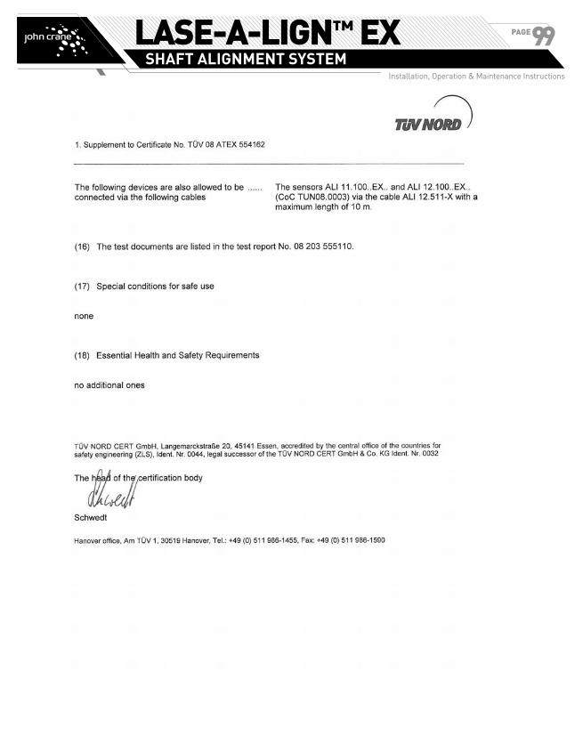
LASE-A-LIGN™ EXSHAFT ALIGNMENT SYSTEM
Installation, Operation & Maintenance Instructions
PAGE99

LASE-A-LIGN™ EXSHAFT ALIGNMENT SYSTEM
Installation, Operation & Maintenance Instructions
PAGE100
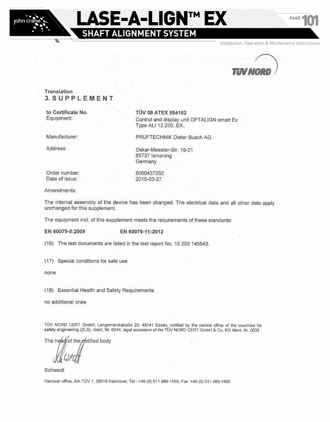
LASE-A-LIGN™ EXSHAFT ALIGNMENT SYSTEM
Installation, Operation & Maintenance Instructions
PAGE101

LASE-A-LIGN™ EXSHAFT ALIGNMENT SYSTEM
Installation, Operation & Maintenance Instructions
PAGE102

LASE-A-LIGN™ EXSHAFT ALIGNMENT SYSTEM
Installation, Operation & Maintenance Instructions
PAGE103
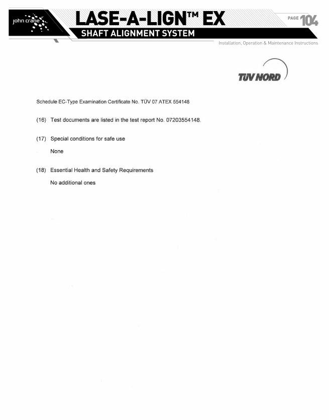
LASE-A-LIGN™ EXSHAFT ALIGNMENT SYSTEM
Installation, Operation & Maintenance Instructions
PAGE104

LASE-A-LIGN™ EXSHAFT ALIGNMENT SYSTEM
Installation, Operation & Maintenance Instructions
PAGE105
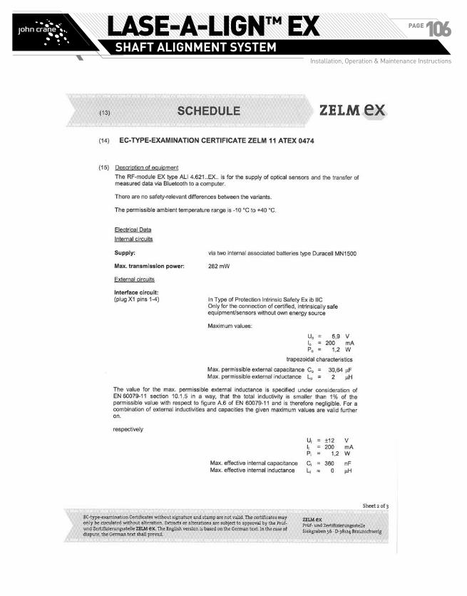
LASE-A-LIGN™ EXSHAFT ALIGNMENT SYSTEM
Installation, Operation & Maintenance Instructions
PAGE106
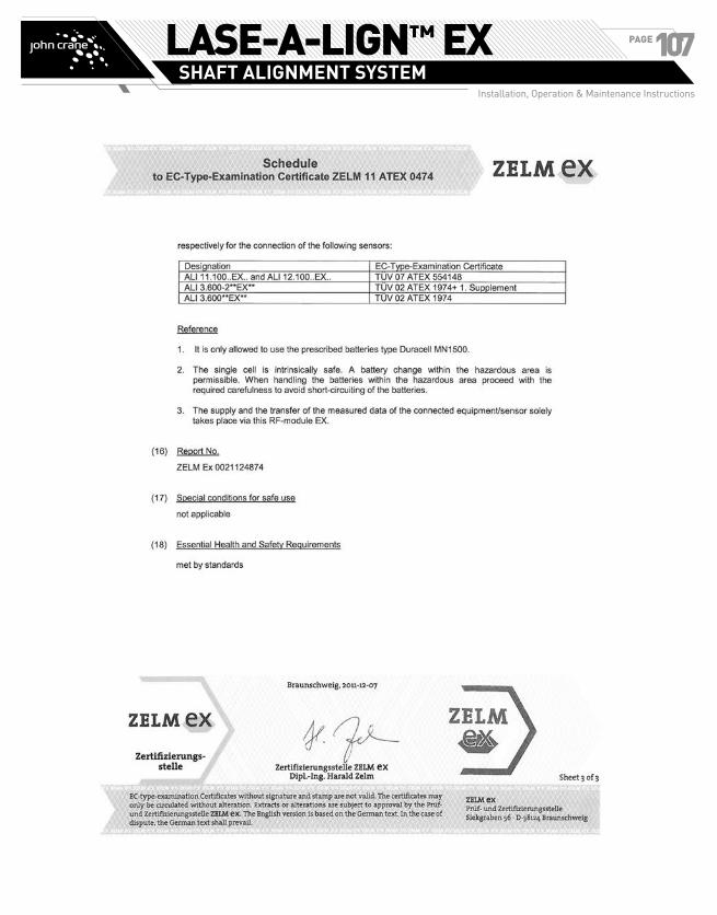
LASE-A-LIGN™ EXSHAFT ALIGNMENT SYSTEM
Installation, Operation & Maintenance Instructions
PAGE107

LASE-A-LIGN™ EXSHAFT ALIGNMENT SYSTEM
Installation, Operation & Maintenance Instructions
PAGE108

LASE-A-LIGN™ EXSHAFT ALIGNMENT SYSTEM
Installation, Operation & Maintenance Instructions
PAGE109

LASE-A-LIGN™ EXSHAFT ALIGNMENT SYSTEM
Installation, Operation & Maintenance Instructions
PAGE110
If the products featured will be used in a potentially dangerous and/or hazardous process, your John Crane representative should be consulted prior to their selection and use. In the interest of continuous development, John Crane Companies reserve the right to alter designs and specifications without prior notice. It is dangerous to smoke while handling products made from PTFE. Old and new PTFE products must not be incinerated. ISO 9001 and ISO 14001 Certified, details available on request.
©2015 John Crane Revised 10/15 www.johncrane.com IOM-LASE-A-LIGN EX
Europe United Kingdom
Tel: 44-1753-224000 Fax: 44-1753-224224
North America United States of America
Tel: 1-847-967-2400 Fax: 1-847-967-3915
Latin America Brazil
Tel: 55-11-3371-2500 Fax: 55-11-3371-2599
Middle East & Africa United Arab Emirates
Tel: 971-481-27800 Fax: 971-488-62830
Asia Pacific Singapore
Tel: 65-6518-1800 Fax: 65-6518-1803