large steel tank fails and rockets to height of 30 meters...
TRANSCRIPT

General rights Copyright and moral rights for the publications made accessible in the public portal are retained by the authors and/or other copyright owners and it is a condition of accessing publications that users recognise and abide by the legal requirements associated with these rights.
• Users may download and print one copy of any publication from the public portal for the purpose of private study or research. • You may not further distribute the material or use it for any profit-making activity or commercial gain • You may freely distribute the URL identifying the publication in the public portal
If you believe that this document breaches copyright please contact us providing details, and we will remove access to the work immediately and investigate your claim.
Downloaded from orbit.dtu.dk on: May 08, 2018
Large Steel Tank Fails and Rockets to Height of 30 meters - Rupture Disc InstalledIncorrectly
Hedlund, Frank Huess; Selig, Robert Simon; Kragh, Eva K.
Published in:Safety and Health at Work
Link to article, DOI:10.1016/j.shaw.2015.11.004
Publication date:2016
Document VersionEarly version, also known as pre-print
Link back to DTU Orbit
Citation (APA):Hedlund, F. H., Selig, R. S., & Kragh, E. K. (2016). Large Steel Tank Fails and Rockets to Height of 30 meters -Rupture Disc Installed Incorrectly. Safety and Health at Work, 7(2), 130-137. DOI: 10.1016/j.shaw.2015.11.004

Vertical cylindrical 90 m³ steel tank operated at "slight overpressure" rockets to height of 30 m –rupture disc overpressure relief device inoperative, installed upside down
Document no. Tank rockets
Version (18)
Date of issue Dec 2015
In-press preprint DRAFT
Safety and Health at Work
http://dx.doi.org/10.1016/j.shaw.2015.11.004

Large steel tank rockets
Tank rockets-18.docx
1
.
Frank Huess HEDLUND a
COWI; Parallelvej 2, DK-2800 Kongens Lyngby, Denmark.
Telephone +45 5640 1330. E-mail: [email protected] b
Technical University of Denmark, (DTU/Compute) DK-2800 Kongens Lyngby, Denmark. E-mail:
Robert Simon SELIG
COWI; Parallelvej 2, DK-2800 Kongens Lyngby, Denmark.
Telephone +45 5640 2936. E-mail: [email protected]
Eva K. KRAGH
COWI; Parallelvej 2, DK-2800 Kongens Lyngby, Denmark.
Telephone +45 5640 2166. E-mail: [email protected]
a corresponding author
b corresponding address
Large steel tank rockets
Tank rockets-18.docx
2
.
Abstract
At a brewery, the base plate-to-shell weld seam of a 90 m³ vertical cylindrical steel tank failed
catastrophically. Leaving the contents behind, the 4 ton tank “took off” like a rocket and landed on
a van, crushing it. The top of the tank reached a height of 30 m. The internal overpressure
responsible for the failure is estimated at 60 kPa. A rupture disc rated at less than 50 kPa provided
overpressure protection and thus prevented the tank from being covered by the European Pressure
Equipment Directive. This safeguard failed and it was later found that the rupture disc had been
installed upside down. The organizational root cause of this incident may be a fundamental lack of
appreciation of the hazards of large volumes of low-pressure compressed air/gas. A contributing
factor may be that the standard P&ID symbol for a rupture disc may confuse and lead to incorrect
installation. Compressed air systems are ubiquitous. The medium is not toxic or flammable.
Nevertheless, such systems operated at "slight overpressure" store a great deal of energy and thus
constitute a hazard that deserves its fair share of safety managers' attention.
Keywords: catastrophic tank failure; isentropic exergy; pressure relief device failure;
Large steel tank rockets
Tank rockets-18.docx
3
.
Table of Contents
1 Introduction 5
2 Process description 8
2.1 Surplus yeast 8
2.2 Indoor collection vessel 8
2.3 The incident outdoor storage tank 9
3 The incident 11
3.1 Witness statement 11
3.2 Investigation 12
3.3 Overpressure protection devices 12
4 Results 15
4.1 Failure mechanism 15
4.2 Strength of the tank's welds 15
4.3 Cause of overpressure 16
4.4 Exergy considerations 16
5 Discussion 18
5.1 Accidents are incubated 18
5.2 Are hazards of compressed air fully recognized? 19
5.3 Rupture disc types 20
5.4 Possible ambiguity in rupture disc P&ID symbol 22
5.5 Rupture disc reliability and SIL considerations 23
5.6 HAZOP considerations 24
6 Conclusion 26
7 Acknowledgements 28
8 References 29

Large steel tank rockets
Tank rockets-18.docx
4
.

Large steel tank rockets
Tank rockets-18.docx
5
.
1 Introduction
Vertical cylindrical tanks for bulk storage of liquids at ambient (atmospheric) pressure or minimal
overpressure are ubiquitous in industry. Catastrophic tank failure is rare but not unheard of.
Although the likelihood is low, the scenario may contribute significantly to the risk as the
consequences can be considerable [1].
The sheer force of a sudden release of large amounts of liquid can propel the walls of the ruptured
tank onto other tanks or structures and cause domino knock-on failures [2]. The sudden gush of
liquid can make dikes or bunds overflow or otherwise overpower barriers erected to provide 100
percent volumetric capacity in cases of tank leakage [3], [4]. Many tanks hold toxic or otherwise
hazardous substances which if released may lead to harm to humans or environmental damage.
A review of catastrophic failures of bulk liquid storage tanks is provided in [1] and new incidents
are occasionally reported [5], [6]. The cases described below are selected because they might not
be well known in English language publications.
• Fuel oil tank failure. In Skærbæk, Denmark, an atmospheric 10,000 m³ tank with heavy fuel
oil failed catastrophically with a "thunderous bang" during the winter of 1959. The flood of
heated fuel oil overtopped the bund and damaged a wall at the nearby power station before the
viscous fluid cooled and solidified. Very little information is available but it appears that the
failure was caused by low temperature brittle failure of the steel shell.
• Fish silage tank failure. In Aabenraa, Denmark, 2011, a tank collapsed with a loud deep
rumble, resembling the sound produced by large metal sheets being shaken. The sudden

Large steel tank rockets
Tank rockets-18.docx
6
.
release of 6,000 t of viscous acid fish silage produced a 14 m high tidal wave, some of which
washed over the bund wall, knocked over trees and damaged parked cars before ending up in
the nearby small community of dwelling houses and allotments and in the harbor. Several
neighboring tanks in the common bund were damaged and one tank containing soya oil started
leaking. There were no human casualties. The topsoil of the affected nearby properties was
replaced but otherwise the tank failure is characterized as an incident resulting in a widespread
unpleasant stench, but which did not cause environmental harm. The emergency responders'
uniforms had to undergo specialist cleaning, a treatment that unfortunately could not be
extended to the vehicles. These continued to have an unmistakable odor of fish [7]. Fish
silage is not a regulated substance and not classified as hazardous. The tank was inspected in
2008 by a specialist tank inspection company and given a clean bill of health until 2018. After
the collapse, the tank owner took the tank inspection company to civil court for professional
malpractice. The civil liability case is currently sub judice and details are unavailable.
• Sulfuric acid tank failure. In Helsingborg, Sweden, 2005, the bottom-to-shell weld of a steel
tank failed catastrophically and released 8,900 m³ of 96% sulfuric acid over an estimated
period of 2½ to 4 minutes. The sudden release of the tank's contents produced a partial
vacuum that caused the roof and shell to implode. Large quantities of acid ended up in the
harbor where the sulfuric acid reacted with seawater to produce hydrogen chloride. It is
believed that within a few minutes "tens of tons" of gaseous and aerosol hydrogen chloride
formed a toxic cloud that extended to a height of 70 m. Consequence modelling indicates that
concentrations that could produce severe irritation extended up to 3-4 km from the site. After
about one hour, when the cloud had drifted about 10 km, concentrations had likely diluted to a
safe level. There were no casualties. The cause was the rupture of a 6 bar, 600 mm diameter
reinforced concrete pipeline one hour earlier, which provided seawater to a nearby industrial
complex for cooling purposes. The seawater line passed close to the tank and the pipeline
Large steel tank rockets
Tank rockets-18.docx
7
.
rupture liquefied the soil and produced a cavity, which undermined the tank and led to a
foundation instability [8].
Contrary to tanks operated at ambient atmospheric pressure this article is concerned with tanks that
operate under very slight overpressures. This includes tanks that are gas blanketed, inerted or
otherwise have a controlled headspace.
For the purposes of this article, we define very slight overpressure as 50 kPa (0.5 bar or about 7.4
psig) which is a limit set in the European Pressure Equipment Directive (PED) [9]. The Directive
applies to the design, manufacture and conformity assessment of pressure equipment and
assemblies with a maximum allowable pressure greater than 50 kPa. It is common practice in
industry to install a rupture disc or another overpressure safety device rated at less than 50 kPa in
order for a vessel to not be classified as pressure equipment and avoid the need to fulfil the rather
onerous requirements of the Directive for written documentation and other formalities.
Tanks originally designed for ambient pressure may undergo modification for them to operate at
slight overpressure. This change of operation may take place for a number of reasons, for instance
vapor recovery, reduction of volatile organic compound (VOC) emissions, odor control, etc. The
article argues that these systems operated at "very slight overpressure" can store a great deal of
energy and thus constitute a hazard that currently may not be fully appreciated. The tank may fail
catastrophically, shoot into the air and spill its contents. The article draws specific attention to the
fact that a rupture disc overpressure safety device can be compromised if installed incorrectly.
Large steel tank rockets
Tank rockets-18.docx
8
.
2 Process description
2.1 Surplus yeast
During the fermentation of beer, yeast cell mass increases three to six-fold. Much of this yeast is
collected as surplus yeast and shipped to external processors for conversion into products such as
protein pills for animal feed [10].
Bottoms from beer fermentation tanks is one source of surplus yeast. Surplus yeast is also
collected from other waste streams and separated by means of filters or centrifuges. While the term
"yeast slurry" technically refers only to dehydrated yeast that has been re-slurried, this article uses
the term for any type of surplus yeast.
2.2 Indoor collection vessel
At a Danish brewery, surplus yeast slurry is first collected in an indoor yeast collection vessel and
then transferred to an outdoor storage tank (Figure 1).
The indoor yeast collection vessel has a volume of 10 m³ and is connected to the brewery's sterile
compressed air system and kept at 100 kPa overpressure. When an operator initiates the transfer of
yeast slurry, a bottom outlet valve opens and the compressed air pushes the viscous yeast slurry to
the 90m3 outdoor storage tank. The control logic closes the bottom valve when a signal from a
liquid level switch low (tuning fork/vibrating fork type) indicates that the vessel is empty.
Large steel tank rockets
Tank rockets-18.docx
9
.
2.3 The incident outdoor storage tank
The outdoor storage tank was constructed in 1973. It was a vertical, cylindrical tank of height 8 m,
diameter 3.8 m, gross volume 96.5 m³, working volume 90 m³, stainless steel type 304, plate
thickness 3 mm, 200 mm mineral wool insulation. The floor plate was sloped towards the outlet
nozzle.
The floor plate rested on a sloping steel structure supported by a concrete base. A circumferential
steel profile at the base of the supporting steel structure served as the point of attachment for the
tank's shell skirt plate.
Because of the age of the tank, only rudimentary construction details are available. Information on
construction code, maximum allowable working pressure (MAWP), specification sheets for
materials of construction, engineering drawings are absent. The tank appears to be designed for
liquid storage at ambient pressure. For many years, the tank was used for temporary storage of an
intermediate brewery liquid and was indeed operated at ambient pressure. About five year earlier,
the tank was moved and changed to surplus yeast service.
Surplus yeast is a biologically active material and an excellent medium for the growth of unwanted
microbes. Occasional nuisance foaming is a concern and the storage tank was therefore modified
to operate at a pressure of 10 kPa to suppress foaming. A spring operated pressure valve was set at
20 kPa (g) to allow for tank breathing during loading, when the incoming liquid reduces the
headspace vapor volume in the tank. An overpressure relief device, a rupture disc (bursting disc),
was installed in the tank's two-inch vent line. The vendor specification sheet gives the burst
pressure range of 43-49 kPa @22 °C.
The change of tank service was likely seen as a rather trivial engineering task. It is probably fair to
assume that the handling of surplus yeast from brewing, a waste stream, commands minimal
managerial attention.
Large steel tank rockets
Tank rockets-18.docx
10
.
Figure 1 Schematic representation of surplus yeast system
Brewery
compressed
air (sterile)
@ 400 kPa (g)
Beer fermentation tanks
Yeast
collection
vessel
10 m³
@ 20 kPa (g)
@ 10 kPa (g)
@ 100 kPa (g)
Rupture disc
@ <50 kPa (g)
LSL
PI
Surplus yeast
storage tank
90 m³
@ 230 kPa (g)
Pressure safety valve
Pressure reduction valve
Spring operated valve
Powered valve
PLC logic
LSL – Level switch low
(g) – overpressure, (gauge)
PI Pressure transmitter,
(for level measurement)
2"
concrete base
floor support structure
floor platePI
welded joints
20
0 m
m m
ine
ral
wo
ol

Large steel tank rockets
Tank rockets-18.docx
11
.
3 The incident
3.1 Witness statement
On the day of the incident, the outdoor yeast storage tank had recently been emptied. It was
receiving its first batch of fermentation tank bottoms from the yeast collection vessel, probably no
more than 3 m³.
Shortly before the tank failure, two refrigeration technicians employed by an external contractor
arrived to service a large ammonia-cooling unit located on the roof of the adjacent building. They
parked their van next to the outdoor yeast storage tank, entered the building and climbed the stairs
to the roof. Immediately after passing through a doorway in a 3 m tall noise protection wall on the
roof they heard a sudden dull poof sound. They turned around and saw the storage tank rising
vertically up in the air. The base of the tank clearly rose above the roof of the adjacent tall green
building, then fell back to the ground landing on their van. They rushed back down and saw that
the van had been crushed (Figure 2, Figure 3).
The storage tank had taken off, almost vertically, like a rocket, leaving the tank contents behind.
Yeast slurry had spilled all over the alley.
The refrigeration technician interviewed insists that the sound was a dull poof rather than a loud
bang. A site visit revealed that the fans of the cooling unit generated some noise and some
attenuation by the noise barrier wall is likely. Still, there is little evidence that a loud noise

Large steel tank rockets
Tank rockets-18.docx
12
.
occurred, and certainly no shock wave, upon tank failure. There is no evidence of blast damage,
such as nearby windows shattered. Nobody else on site seems to have heard anything unusual.
3.2 Investigation
A specialist metallurgy company examined the failed tank, the supports and the welds. The tank
shell skirt had been joined to the circumferential steel profile at the base of the supporting steel
structure by 58 short welds each distanced about 0.15 m. The short welds were absent in two
adjacent arc sections, each about 0.5 m length, which were identified as the probable point of
failure initiation. The position of the two arc segments were opposite the tall green building, which
would imply that the tank would tilt towards that building immediately before rocketing. This is
consistent with impact damage to that building's exterior panels, when the tank descended (Figure
4).
L-shaped angles made of sheet metal were joined to the base rim of the shell skirt. The angles
extended under the circumferential steel profile, serving as crude anchors. Many of the anchors
were found to be weakened by corrosion.
Tank shell thickness was measured to be 3.36 mm. Measurement of the welds at the base produced
heights in the range 1.25-2.81 mm and widths in the range 0.09-0.8 mm – i.e. weak welds.
3.3 Overpressure protection devices
Testing revealed that the spring operated pressure valve on the tank opened at 20 kPa, as specified.
The capacity was limited however, due to small-bore (8.5 mm diameter) connecting pipework.
The rupture disc was intact. It was a reverse buckling type device that had been installed upside
down (i.e. with the dome facing away from the tank). The vendor stated when asked, that the

Large steel tank rockets
Tank rockets-18.docx
13
.
rupture disc likely could withstand an overpressure of at least three times the stamped pressure (i.e.
150 kPa or more) before bursting, if installed upside down.
Figure 2 The van is visible under the tank. Tank contents washed up on elevated platform.
((Photo courtesy of the company)

Large steel tank rockets
Tank rockets-18.docx
14
.
Figure 3 Tank landed on van, crushing it. The tank's original position (the sloping support
structure for the tank floor plate) seen in foreground. The tank floor plate is seen center
left. (Photo courtesy I.W. Michaelsen)
Figure 4 The tank rose almost vertically in the air and the base of the tank rose higher than the 19
m tall green building. Whilst descending, the tank impacted and deformed the building's
exterior wall panels (Photo courtesy: Frank H. Hedlund)
Large steel tank rockets
Tank rockets-18.docx
15
.
4 Results
4.1 Failure mechanism
The likely failure mechanism is that excess internal overpressure acting on the roof created an
uplift force on the shell, which strained the welds and the corroded L-shaped anchors at the base.1
The welds at the base skirt then failed, resulting in shell uplift. The 3 mm floor plate, which had
had little stiffness, then bulged. This lead to catastrophic failure of its circumferential weld seam.
Immediately after that, the tank's pipe connections were torn off. The tank then lifted off and
spilled its contents.
4.2 Strength of the tank's welds
The tank was not designed for internal overpressure and its ability to withstand an overpressure is
not stated in the sparse documentation available. Not accounting for the effect of anchors, sketch
mechanical engineering calculations based on standard material properties indicate that the
probable internal overpressure leading to weld failure would be 45 kPa for the welds at the base
and 35 kPa for the floor plate.
A mechanical engineering analysis of this nature is approximate. The effect of the anchors is
unknown and standard table values for material tensile properties were used in the computation
1 Uplift and anchoring requirements are covered e.g. in API 650, appendix F [22]

Large steel tank rockets
Tank rockets-18.docx
16
.
procedure. No samples of the metal were taken for laboratory tests to determine actual material
properties.
4.3 Cause of overpressure
The most likely source of overpressure is gas breakthrough from the yeast collection vessel,
operating at 100 kPa. The bottom liquid level switch (tuning fork type) may have failed to detect
low level if covered in viscous and sticky surplus yeast. As an alternative hypothesis, an operator
may have set the transfer sequence in manual override mode to ensure a complete clear out of the
tank, and then forgotten to return and terminate the transfer in time.
4.4 Exergy considerations
When a pressurized gas expands against a constant external pressure it does work on the
surroundings, i.e. some of the energy of the expanding gas is lost by pushing the atmosphere away.
This is accounted for in the concept of exergy, which is the maximum useful work possible that can
be obtained from an expanding gas that comes into equilibrium with its constant pressure
environment. Because a pressure vessel burst is rapid, there is little heat exchange with the
surroundings. Kurttila [11] argues the process should be considered adiabatic and hence the
maximum useful work possible is represented by the isentropic exergy.
For an ideal gas, the isentropic exergy, E, is (equation 2.1.7 in [11])
� = γγ − 1��� 1 − ����� ����� �� −V���� − ���
where γ is the ratio of specific heats, which for air is 1.4, p is pressure, V is volume, subscript 1 is
start conditions, subscript a is ambient, all units in SI.

Large steel tank rockets
Tank rockets-18.docx
17
.
The tank's increase in potential energy can be computed if the maximum height it reached is
known. The first law of thermodynamics (the law of conservation of energy) can then be applied to
compute the theoretical minimum internal overpressure required to attain this height.
In practice, not all the isentropic exergy will be converted to potential energy. Energy is lost in
tearing of pipework, steel plate deformation, kinetic energy of the expelled liquid, friction from the
viscous yeast slurry, possible shock wave generation, and others. These losses are unknown.
It is arbitrarily assumed that 90 percent of the isentropic exergy was converted to potential energy.
The mass of the tank is estimated at 4000 kg and the base of the tank is assumedto have risen to a
height of 21 m. The green building in Figure 4 is 19 m high... The internal overpressure then
computes to about 60 kPa.

Large steel tank rockets
Tank rockets-18.docx
18
.
5 Discussion
5.1 Accidents are incubated
At face value, the root cause of this incident is the upside down installation of the rupture disc. It
took place years earlier, when a pipe fitter installed the device. From that very moment, the tank
was vulnerable to single cause failure, for instance a gas breakthrough from the collection vessel.
Barry Turner, in his influential 1978 book [12], was the first to articulate the idea that accidents are
incubated. Like a resident pathogen in the human body, a vulnerability in the design may be
present for years before it causes damage. James Reason later embraced and elaborated this idea in
his concept of latent and active failures that create holes in the system's barriers and safeguards -
the well-known Swiss cheese model. He also developed a theoretical framework, that emphasizes
that, ultimately, organizational processes should be considered responsible for accidents [13], [14]
for accident prevention work to be effective
In Reason's framework, decisions taken in the higher echelons of an organization seed so-called
organizational pathogens into the system at large. They take many forms: including limited
managerial oversight, inadequate budgets, lack of control over contractors, excessive cost-cutting,
blurred responsibilities and production pressures. The adverse effects of these pathogens are
transported along two principal pathways to the workplace. They act on barriers and safeguards to
create latent failures, which are longstanding dormant weaknesses or undiscovered shortcomings;
and they act upon local working conditions to promote active failures, which are mistakes,

Large steel tank rockets
Tank rockets-18.docx
19
.
violations or component failures. When latent failures combine stochastically with active failures
or with triggers, the circumstances are suddenly favorable for all factors to combine into an
accident trajectory.
Applying the framework to this particular case, the active failure is the malfunction of a level-
switch low transmitter or the operator carrying out the transfer in manual override mode. The
latent failure is the upside down installation of the rupture disc, an error which rendered the
overpressure protection device inoperative.
Although there were no fatalities or injuries, the incident could have had a worse outcome. Had the
refrigeration technicians arrived a few minutes later, the tank might have landed on their van whilst
they were still inside it. Had the tank damaged ammonia-cooling pipelines there could have been a
release of ammonia.
5.2 Are hazards of compressed air fully recognized?
Lack of data quickly make a discussion of underlying shortcomings of the organizational processes
speculative. After the incident, the brewery expressed complete astonishment, believing that an
impossible event had taken place. This indicates that the organizational root cause of this incident
may be a fundamental and perhaps widespread lack of appreciation of the hazards of relatively
low-pressure compressed air.
The storage tank, originally designed for ambient pressure only, was changed to 10 kPa
overpressure service, to suppress nuisance foaming. The overpressure appears modest and the
change of service seems to have been subjected to minimal scrutiny. For a brewery, which
routinely handles very large volumes of carbonated drinks kept at pressures that are at least ten
times higher, this is plausible and unsurprising. The spring operated pressure relief valve seems to
have been set arbitrarily at 20 kPa(g). Due to compression of the vapor head space during yeast
Large steel tank rockets
Tank rockets-18.docx
20
.
slurry transfer, the normal operating pressure in the tank will therefore be in the range 10-20
kPa(g).
The rupture disc seems to have been installed only to ensure that the vessel did not need to fulfil
the European Pressure Equipment Directive's requirements since the internal pressure would never
exceed the Directive's arbitrary limit of 50 kPa(g). As shown in Table 1 however, there is much
difference in the hazard potential, here expressed as exergy content, of a tank operating at 10-20
kPa(g), and at near 50 kPa(g). Even if the rupture disc had been operational, the consequences of
an instantaneous tank failure at a pressure lower than 50 kPa would still have been dramatic. This
scenario cannot be dismissed as the welds were predicted to fail at pressures in the range 35-45
kPa.
Overpressure Headspace exergy is able to lift storage
tank (centre of gravity) by
10 kPa 0.5 m
20 kPa 2.4 m
30 kPa 5.4 m
40 kPa 9.5 m
50 kPa 15 m
60 kPa 21 m
70 kPa 27 m
Table 1 Overpressure in headspace of an almost empty 90 m³ storage tank weighing 4,000 kg
can throw the tank to considerable height (based on exergy considerations)
5.3 Rupture disc types
A rupture disc is a membrane that fails at a predetermined differential pressure. The device
typically comprises an assembly of components including a dome shaped disc and two special
insert type holders that fit inside the bolt hole circle of standard piping flanges. The disc is
Large steel tank rockets
Tank rockets-18.docx
21
.
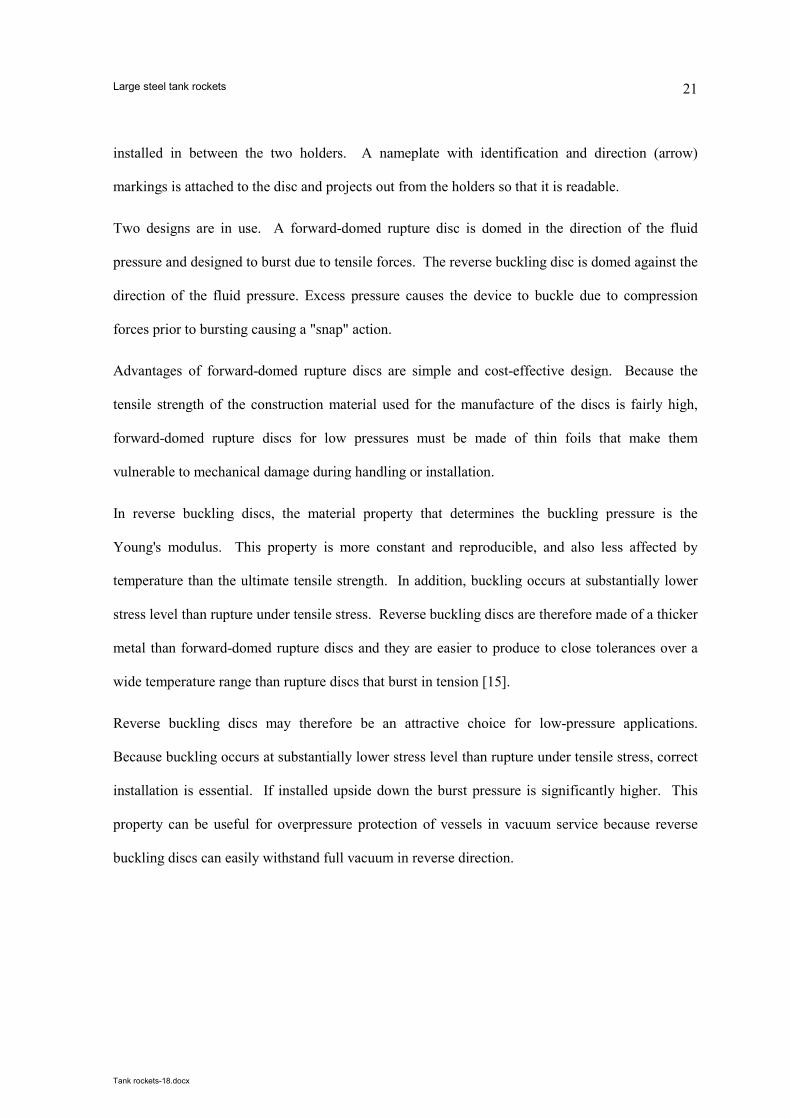
installed in between the two holders. A nameplate with identification and direction (arrow)
markings is attached to the disc and projects out from the holders so that it is readable.
Two designs are in use. A forward-domed rupture disc is domed in the direction of the fluid
pressure and designed to burst due to tensile forces. The reverse buckling disc is domed against the
direction of the fluid pressure. Excess pressure causes the device to buckle due to compression
forces prior to bursting causing a "snap" action.
Advantages of forward-domed rupture discs are simple and cost-effective design. Because the
tensile strength of the construction material used for the manufacture of the discs is fairly high,
forward-domed rupture discs for low pressures must be made of thin foils that make them
vulnerable to mechanical damage during handling or installation.
In reverse buckling discs, the material property that determines the buckling pressure is the
Young's modulus. This property is more constant and reproducible, and also less affected by
temperature than the ultimate tensile strength. In addition, buckling occurs at substantially lower
stress level than rupture under tensile stress. Reverse buckling discs are therefore made of a thicker
metal than forward-domed rupture discs and they are easier to produce to close tolerances over a
wide temperature range than rupture discs that burst in tension [15].
Reverse buckling discs may therefore be an attractive choice for low-pressure applications.
Because buckling occurs at substantially lower stress level than rupture under tensile stress, correct
installation is essential. If installed upside down the burst pressure is significantly higher. This
property can be useful for overpressure protection of vessels in vacuum service because reverse
buckling discs can easily withstand full vacuum in reverse direction.
Large steel tank rockets
Tank rockets-18.docx
22
.
5.4 Possible ambiguity in rupture disc P&ID symbol
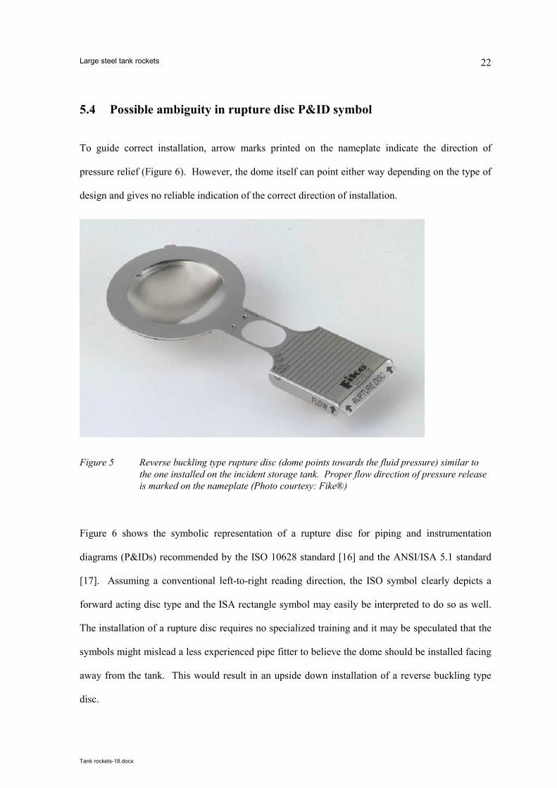
To guide correct installation, arrow marks printed on the nameplate indicate the direction of
pressure relief (Figure 6). However, the dome itself can point either way depending on the type of
design and gives no reliable indication of the correct direction of installation.
Figure 5 Reverse buckling type rupture disc (dome points towards the fluid pressure) similar to
the one installed on the incident storage tank. Proper flow direction of pressure release
is marked on the nameplate (Photo courtesy: Fike®)
Figure 6 shows the symbolic representation of a rupture disc for piping and instrumentation
diagrams (P&IDs) recommended by the ISO 10628 standard [16] and the ANSI/ISA 5.1 standard
[17]. Assuming a conventional left-to-right reading direction, the ISO symbol clearly depicts a
forward acting disc type and the ISA rectangle symbol may easily be interpreted to do so as well.
The installation of a rupture disc requires no specialized training and it may be speculated that the
symbols might mislead a less experienced pipe fitter to believe the dome should be installed facing
away from the tank. This would result in an upside down installation of a reverse buckling type
disc.

Large steel tank rockets
Tank rockets-18.docx
23
.
As mentioned above the rupture disc on the outdoor storage tank that was installed upside down
was precisely a reverse buckling type disc.
ISO 10628-2:2012
ANSI/ISA 5.1:2009
Figure 6 The recommended symbolic representations of a rupture disc for
overpressure protection bear resemblance to the conventional forward
acting type and may confuse correct installation of a reverse buckling
type.
We have consulted two valve selection handbooks used by design engineers [15], [18]. Both
handbooks have a chapter on rupture disc selection, sizing and installation. Neither handbook
mentions the potential problem of upside down installation of reverse buckling rupture discs.
5.5 Rupture disc reliability and SIL considerations
A rupture disc is often considered more reliable than a spring operated pressure safety valve due to
simpler construction and fewer critical components. Some vendors offer rupture discs rated for
Safety Integrity Level (SIL) 3, indicating that the probability of failure on demand is less than 1 in
1000.
The peer-reviewed literature on the subject of reliability of rupture discs appears relatively sparse.
Some issues are raised in papers from the 1980s [19], [20]. Industry sources inform us however,
that significant advances have been made, particularly regarding high-precision laser ablation

Large steel tank rockets
Tank rockets-18.docx
24
.
techniques to score, not cut, the metal membrane, to control burst pressure, and issues raised 30
years ago do not apply today. A recent paper [21] examines the degradation and opening behavior
of the specialty subgroup of knife blade reverse buckling rupture discs but does not comment on
SIL.
We have been unable to identify a review of mechanisms that may compromise rupture disc
reliability. Discussions with industry experts indicate that even a modest deformation of the dome
of a reverse buckling rupture discs is a concern because it may affect the pressure at which
buckling takes place. Reverse buckling rupture discs are therefore used in gas service only.
Exposure to incompressible media (e.g. an overfill event) may deform the dome, and increase the
pressure at which buckling, snap action and rupture, take place. Incorrect torque applied to the
bolts holding together the rupture disc assembly may also influence rupture disc reliability. A too
low or an unevenly distributed torque can result in slippage of the rupture disc. The misalignment
may potentially expose the rupture disc to uneven loads leading to slight plastic deformation of the
disc plate, which in turn may result in increased opening pressure of the membrane. An over-
torque may damage the clamping zone of the rupture disc and lead to puncture or premature failure
of the membrane. More research into these mechanisms is desirable.
In summary, we believe that a high SIL rating would require strict verification activities, not only
during manufacture but also during installation and operation, to ensure that the device is not
installed upside down or otherwise compromised.
5.6 HAZOP considerations
A detailed discussion of accident causation and risk management theories is outside the scope of
this article. It suffices to say that both latent and active failures can be discovered before an
accident takes place, using techniques of systematic risk analysis such as HAZOP study. A
HAZOP study would very likely have identified the potential for level switch low failure and

Large steel tank rockets
Tank rockets-18.docx
25
.
subsequent gas breakthrough. A HAZOP study however, is always based on diagrams and other
forms of written documentation and may not pick up mistakes in installation.
The question about the reliability of the rupture disc might have been raised at the HAZOP session
with an action for somebody to go and check whether it had been installed correctly, in particular if
knowledge from past failures has been available to the team members.

Large steel tank rockets
Tank rockets-18.docx
26
.
6 Conclusion
Compressed air systems are ubiquitous in industry and elsewhere. The material is neither toxic nor
flammable. Over time, such systems may end up being regarded as non-hazardous utility systems
that present minimal risk in practical day-to-day operations. As this case shows, compressed air
needs to be given adequate attention by the safety manager.
The working pressure of many plant air systems is in the range of 600-800 kPa. This case presents
the failure of a 4 t steel tank which “took off”, reaching a height of about 30 m. The overpressure
causing catastrophic tank failure was about 60 kPa. The tank's breathing/venting system had
insufficient capacity for a compressed air gas break-through and the ultimate overpressure
protection system, a rupture disc, was inoperative and had been for years.
The case offers the following accident prevention lessons
• Care should be taken if a tank originally designed for ambient pressure undergoes
modification to operate at slight overpressure
• At the organizational level, there appears to be a lack of appreciation of the hazards of large
volumes of low-pressure compressed air and the amount of energy that can be released in case
of failure.
• Installing a rupture disc upside down, an innocent human mistake by a pipe fitter, rendered the
device inoperable.
Large steel tank rockets
Tank rockets-18.docx
27
.
• The P&ID symbols in use for rupture discs may be a possible source of confusion during
installation of reverse buckling type discs.
• The nameplate of a rupture discs clearly indicates the flow direction and allows simple visual
verification of correct installation without interruption of production. Such inspections should
be included in safety audits.
• The rupture disc seems to have been installed only to avoid being covered by the European
Pressure Equipment Directive's arbitrary limit of 50 kPa(g). Had the tank failed at a slightly
lower pressure than 50 kPa, the consequences would still have been dramatic. The burst
pressure of the rupture disc could easily have been specified at a lower value for the tank in
question, significantly reducing the hazard (provided that it had been correctly installed).
We are of the opinion that these lessons are relevant not just for the beverage sector but for industry
as a whole.
At other facilities, comparable storage arrangements are in common use for more hazardous
substances than yeast slurry. Flammable substances often have an inert gas (nitrogen) blanketing
system to prevent a flammable atmosphere from forming in the headspace.
A damaged tank here could lead to the release of toxic or flammable substances such as organic
solvents. Fatalities or acute and chronic health effects could result from exposure to the chemicals
and of course fatalities or injuries to nearby personnel if a flammable substance ignites. Damage to
the environment is likely if the released chemicals enter the drains and sewage systems.
We hope that this communication will contribute to an improved appreciation of the hazards of
systems operated at "slight overpressure" in general and of plant compressed air systems in
particular.

Large steel tank rockets
Tank rockets-18.docx
28
.
7 Acknowledgements
Factual information on this incident is based on a site visit shortly after the tank failure, an
interview with one of the refrigeration technicians, follow-up interviews with the brewery's
production supervisor, and a report from the specialist metallurgy company, which the brewery
kindly made available.
The brewery has been forthcoming in requests for information on the condition of anonymity. We
believe that incidents with significant learning potential like this one are seldom communicated to a
wider audience, and sometimes not communicated at all. We would like to extend our gratitude to
the brewery for granting access to information, which made this article possible.
This article has been produced as voluntary work and has not received any funding. Opinions
expressed are those of the authors, not those of their employers’ or organizations’.
Large steel tank rockets
Tank rockets-18.docx
29
.
8 References
[1] "Thyer AM, Jagger SF, Atherton W, Ash JW, A review of catastrophic failures of bulk liquid
storage tanks, Loss Prevention Bulletin, 205, 3-11, 2009. (no DOI found)".
[2] "Chemical alert: Rupture hazard from liquid storage tanks, EPA 550-F-01-001, United States
Environmental Protection Agency, January 2001".
[3] "Thyer AM, Hirst IL, Jagger SF, Bund overtopping - the consequence of catastrophic tank
failure, J. Loss Prev. Proc. Ind. 15(5):357-363, 2002 (http://dx.doi.org/10.1016/s0950-
4230(02)00023-2)".
[4] "Atherton W, Ash JW, Alkhaddar RM, An empirical study into overtopping and dynamic
pressures on a bund wall post catastrophic failure of a storage vessel, IChemE Symposium
Series No. 153, 2007".
[5] "Allied Terminals, Inc.– Catastrophic Tank Collapse (Two Serious Injuries, Community
Evacuation. Chesapeake, Virginia November 12, 2008, Report No. 2009-03-I-Va. U.S.
Chemical Safety and Hazard Investigation Board, May 2009.".
[6] "Geary W, Hobbs J, Catastrophic failure of a carbon steel storage tank due to internal
corrosion, Case Studies in Engineering Failure Analysis 1(4): 257–264, 2013
(http://dx.doi.org/10.1016/j.csefa.2013.09.002)".
[7] "Weinreich E., Vellykket men stinkende indsats, Brandvæsen 9(6):75-77, Aug 2011 (In

Large steel tank rockets
Tank rockets-18.docx
30
.
Danish)".
[8] "Olycka med utsläpp av svavelsyra vid Kemira Kemi AB i Helsingborg, M län, den 4 februari
2005, Statens haverikommission (SHK) Swedish Accident Investigation Board, Rapport RO
2008:02, Karlstad, May 2008. (In Swedish)".
[9] "The Pressure Equipment Directive (PED), Directive 97/23/EC of the European Parliament
and of the Council of 29 May 1997. Official Journal of the European Union 1997L0023 -
01.01.2013 - 002.001 - 3".
[10] "Huige N.J, Brewery By-Products and Effluents. In: Priest and Stewart (eds) Handbook of
brewing.--2nd ed. Taylor & Francis, 2006. (http://dx.doi.org/10.1201/9781420015171.ch18)".
[11] "Kurttila H., Isentropic Exergy and Pressure of the Shock Wave Caused by the Explosion of a
Pressure Vessel, (PhD thesis), Lappeenranta University of Technology, Lappeenranta,
Finland, 2003".
[12] "Turner B., Man-Made Disasters, Wykeham Science Press, London, 1978".
[13] "Maurino D.E., Reason J., Johnston N., Lee R.B., Beyond aviation human factors: Safety in
high technology systems. Ashgate, 1995".
[14] "Reason, J.T., Managing the risks of organizational accidents, Ashgate, 1997".
[15] "Smith P, Zappe RW, Valve Selection Handbook (Fifth Edition) Engineering Fundamentals
for Selecting the Right Valve Design for Every Industrial Flow Application, Chapter 6 -
Rupture discs. Gulf, 2004. Pages 227–267, doi:10.1016/B978-075067717-2/50006-7".
[16] "ISO 10628-2:2012, Diagrams for the chemical and petrochemical industry - Part 2: Graphical
symbols, European Committee for Standardization (CEN), 2012".
[17] "ANSI/ISA-5.1-2009, Instrumentation Symbols and Identification, The International Society
of Automation (ISA), NC, USA, 2009".
[18] "Lipták BG, Instrument Engineers Handbook, Chapter 7.17 Rupture discs, Taylor & Francis
2003.".
Large steel tank rockets
Tank rockets-18.docx
31
.
[19] "Watton BK, Brodie GW, Reverse domed buckling discs, a pressure relief device, their
performance and problems, Institution of Chemical Engineers Symposium Series 85: 51-65,
Rugby, UK, 1984. (no DOI found)".
[20] "Swift I, Experimental study of the consequences of improperly specified or installed rupture
discs, Paper no. 51E, American Institute of Chemical Engineers, Summer National Meeting
Minneapolis, Minnesota, Aug 16-19, 1987 (no DOI found)".
[21] "Schrank M, Investigation on the degradation and opening behavior of knife blade burst disks,
Loss Prev. Proc. Ind 32:161-164, 32 (2014) (http://dx.doi.org/10.1016/j.jlp.2014.08.011)".
[22] "Welded Steel Tanks for Oil Storage. API Standard 650. 10th ed. Addendum 3. American
Petroleum Institute, 2003.".