lap splice performance of reinforcing bar in high
TRANSCRIPT

LAP SPLICE PERFORMANCE OF REINFORCING BAR IN HIGH PERFORMANCE SYNTHETIC FIBER REINFORCED CEMENTITIOUS COMPOSITES UNDER REPEATED LOADINGS
Esther Jeon, Sun-Woo Kim, Young-Oh Lee, Jang-Bae Byun and Hyun-Do Yun
Dept. of Architectural Engineering, Chungnam National University, Republic of Korea
Abstract
The primary objective of this research is to investigate the lap splice performance and bond stress of deformed reinforcing bars embedded in high-performance fiber-reinforced cementitious composites (HPFRCC). In this paper, the effects of reinforcing fibers on the lap splice strength of reinforcing bars in tension were experimentally investigated. A total of 6 specimens were made and tested in axial tension. The variables in this study covered matrix ductility [reinforcing fibers: polypropylene (PP) and polyethylene (PE) fiber] and lap splice length (90 and 120% of development/splice length in ACI 318-05 lap splice provisions). Three strain gages located on the surface of reinforcing bar were placed to monitor the strain of the reinforcement during the deformation process. The scope of the investigations on the splice strength of reinforcing bars in tension in absence of transverse reinforceiment in comparison with plain unconfined concrete. The current experimental results demonstrated clearly that the addition of synthetic fibers in cement matrixes increases significantly the lap splice performance of reinforcing bars in tension. Lap splice strength by adding PE fiber in 1.5 percent by volume increased 30.11 ~ 88.63 percent more than that of normal concrete. Also, the presence of fibers increased the number of cracks formed around the spliced bars, delayed the growth of the splitting cracks, and consequently, improved the ductility of bond failure.
1. INTRODUCTION In Korea, precast concrete frame construction has been used extensively for industrial and
commerical facilities due to its potential benefits in term of construction speed, high quality control, and saving in costs. However, it is required to develop a adquate connection between the precast members because recently, seismic design code in Korea is more intensified in consideration of increasing the seismic harzards in the Korean Peninsula. Such a precast member connection must meet the demands of strength and damage tolerance such as ductility and energy dissipation capacity. It is well known that the seismic performance of precast component connections is dependent on the amount/details of joint reinforcements and CIP(Cast-in-place) joint materals [1]. In essence, an increased amount and complicated details
437
of connection reinforcement result in the increas in construction time and cost. In the past decade, efforts [2, 3] to improve quasibrittle characteristic of fiber-reinforced
concrete (FRC) have led to innovative materials i.e. HPFRCC which uniquely exhibit multiple, fine cracks and ductile strain-hardening behavior resembling ductile metal upon loading in tension. Advances in HPFRCC have been so rapid that the application of serveral HPFRCC materials to seismic-resistant structures has been discussed [4].
This research aimed at developing a strong and damage-tolerant connections between precast components is a preceeding study. This paper provides the basic characteristics of the two types of HPFRCC with polypropylene (PP) and polyethylene(PE) fiber in terms of uniaxial tensile tests. Also, the effects of HPFRCC’s tensile characteristics on the the lap splice performance and crack procedure are experimentally investigated.
2. CHARACTERISTICS OF HPFRCC
2.1 Materials and mix proportions The synthetic fibers used in this study were PP and PE. As shown in Table 1, the PP fiber
had a diameter of 0.04 mm, a length of 15 mm and a tensile strength of 600 MPa. Also, the PE fibers 15 mm in length and tensile strength of 2,500 MPa were used. Silica sand with a specific gravity of 2.61 and grain sizes ranging from 105 to 120 µm was used. Superplasticizers were used to control the workability of high strength cement composite (50 MPa).
The mix proportions of PP2.0, PE1.5 and normal concrete(Concrete) are shown in Table 2. Test specimens were named according to the types of reinforcing fibers (PP2.0 for PP-HPFRCC, PE1.5 for PE-HPFRCC) and fiber volume fraction. In PP2.0 and PE1.5, the content of fiber was 2.0, 1.5% by volume fraction respectively. The cement composites was made using ASTM Type III cement, commercial silica sand and aggregate, at w/c ratio of 0.37 for concrete and 0.45 for PP2.0 and PE1.5. Table 1: Proportions of fibres
Fiber
type
Specific gravity
(kg/m3)
Length
(mm)
Diameter
(µm)
Aspect ratio
(l/df)
Tensile strength
(MPa)
Young’s modulus
(GPa)
PP 0.91 15 40 375 600 5
PE(DYN-A) 0.97 15 12 1,250 2,500 75
Table 2: Mixture proportions of composites
Unit weight(kg/m3) Specimen
notation W/C
Vf
(%) Cement Sand Aggregate Water
Concrete 0.37 - 459.0 759.0 570.0 170.0
PP2.0 0.45 2.0 1036.0 414.4 - 466.2
PE1.5 0.45 1.5 1041.5 416.6 - 468.7
438
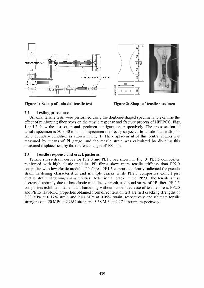
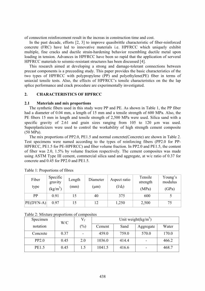
Figure 1: Set-up of uniaxial tensile test Figure 2: Shape of tensile specimen
2.2 Testing procedure Uniaxial tensile tests were performed using the dogbone-shaped specimens to examine the
effect of reinforcing fiber types on the tensile response and fracture process of HPFRCC. Figs. 1 and 2 show the test set-up and specimen configuration, respectively. The cross-section of tensile specimen is 80 x 40 mm. This specimen is directly subjected to tensile load with pin-fixed boundary condition as shown in Fig. 1. The displacement of this central region was measured by means of PI gauge, and the tensile strain was calculated by dividing this measured displacement by the reference length of 100 mm.
2.3 Tensile response and crack patterns Tensile stress-strain curves for PP2.0 and PE1.5 are shown in Fig. 3. PE1.5 composites
reinforced with high elastic modulus PE fibres show more tensile stiffness than PP2.0 composite with low elastic modulus PP fibres. PE1.5 composites clearly indicated the pseudo strain hardening characteristics and multiple cracks while PP2.0 composites exhibit just ductile strain hardening characteristics. After initial crack in the PP2.0, the tensile stress decreased abruptly due to low elastic modulus, strength, and bond stress of PP fiber. PE 1.5 composites exhibited stable strain hardening without sudden decrease of tensile stress. PP2.0 and PE1.5 HPFRCC properties obtained from direct tension test are first cracking strengths of 2.08 MPa at 0.17% strain and 2.03 MPa at 0.05% strain, respectively and ultimate tensile strengths of 4.20 MPa at 2.26% strain and 5.58 MPa at 2.27 % strain, respectively.
439

(a) PP2.0 (b) PE1.5
Figure 3: Typical tensile response of HPFRCC
3. PERFORMANCE OF LAP SPLICES IN HPFRCC
3.1 Specimen configuration A summary of the test specimens is provided in Table 3. The dimensions and reinforcing
bar arrangements of the specimens are shown in Fig. 4. Parameters cover lap splice length and matrix type. Lap splice specimen had 120 x 100 mm of cross section and 600 (730) mm of length. The spliced length of the bars was 400 (530) mm [90(120) percent of lap splice length(ld) calculated by ACI 318-05 lap splice provisions]. A 19 mm diameter deformed bars were spliced centrally.
3.2 Test rig and procedure As shown in Fig. 4, two linear variable differential transducers (LVDTs) were installed to
measure the displacement of the specimen of lap splice region. Three wire strain gauges were attached to estimate the strain distribution of reinforcing bar according to splice length. Loading is carried out with repeated manner. The tests were carried out using a displcement control (500 to 4,000 strain in term of strain of reinforcing bar embedded in HPFRCC). All specimens were loaded vertically in a 1,000 kN capacity servo-hydraulic Universal Testing Machine and gripped at the protruding ends of the steel reinforcement so that the tensile load was transferred from the reinforcing bar to lap splice at the center of specimen.
3.3 Failure patterns A typical crack pattern of the lap splice has been shown in Fig. 5. During the early stage of
load application, tensile cracks initiated at the lap splice edge of reinforcing bars. As the load increased, tensile cracks formed randomly along the entire length of the lap splice region. These cracks progressed to the center of specimen. For Concrete specimen, there is no distributed cracking that occurs before localization. Only four cracks formed in the specimen before one of the cracks began to localize. The use of PE fiber, compared with PP, greatly improved the fracture process by allowing for the formation of multiple microcracks before the macrocrack began to localize. The addition of the microfibers reduced the widening of coalesced cracks and induced the formation of multiple cracks before the peak load. The
440
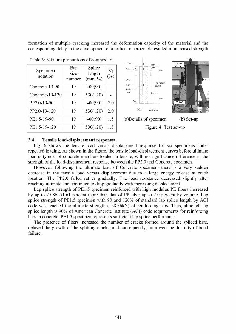
formation of multiple cracking increased the deformation capacity of the material and the corresponding delay in the development of a critical macrocrack resulted in increased strength.
Table 3: Mixture proportions of composites
Specimen notation
Bar size
number
Splice length
(mm, %)
Vf (%)
Concrete-19-90 19 400(90) -
Concrete-19-120 19 530(120) -
PP2.0-19-90 19 400(90) 2.0
PP2.0-19-120 19 530(120) 2.0 D22
Strain Gage
50
W.S.G 3
W.S.G 2
W.S.G 1
LVDT
50
Lap splice length
unit:mm
100
Center
100
3030
PE1.5-19-90 19 400(90) 1.5 (a)Details of specimen (b) Set-up
PE1.5-19-120 19 530(120) 1.5 Figure 4: Test set-up
3.4 Tensile load-displacement responses Fig. 6 shows the tensile load versus displacement response for six specimens under
repeated loading. As shown in the figure, the tensile load-displacement curves before ultimate load is typical of concrete members loaded in tensile, with no significance difference in the strength of the load-displacement response between the PP2.0 and Concrete specimen.
However, following the ultimate load of Concrete specimen, there is a very sudden decrease in the tensile load versus displacement due to a large energy release at crack location. The PP2.0 failed rather gradually. The load resistance decreased slightly after reaching ultimate and continued to drop gradually with increasing displacement.
Lap splice strength of PE1.5 specimen reinforced with high modulus PE fibers increased by up to 25.86~51.61 percent more than that of PP fiber up to 2.0 percent by volume. Lap splice strength of PE1.5 specimen with 90 and 120% of standard lap splice length by ACI code was reached the ultimate strength (168.56kN) of reinforcing bars. Thus, although lap splice length is 90% of American Concrete Institute (ACI) code requirements for reinforcing bars in concrete, PE1.5 specimen represents sufficient lap splice performance.
The presence of fibers increased the number of cracks formed around the spliced bars, delayed the growth of the splitting cracks, and consequently, improved the ductility of bond failure.
441
0
20
40
60
80
100
120
140
160
180
0 1 2 3 4 5 6
D isplacem ent (m m )
Load (kN)
C o ncrete-19-120
l
P
P
Pcr : 29.40kNPm ax : 124.66kN
(a)
(b)
(c)
(c) (a) Concrete
0
20
40
60
80
100
120
140
160
180
0 1 2 3 4 5 6
D isplacem ent (m m )
Load (kN)
P P 2.0-19-120
l
P
P
Pcr : 21.56kNPm ax : 128.87kN
(a)
(b)
(c)
(d)
(b) PP2.0
0
20
40
60
80
100
120
140
160
180
0 1 2 3 4 5 6D isplacem ent (m m )
Load (kN)
P E 1.5-19-120
l
P
P
Pcr : 48.02kNPm ax : 162.19kN
(a)
(b) (c) (d)
(d) (c) PE1.5
Figure 5: Failure patterns (120% of lap splice length by ACI code)
442

0
20
40
60
80
100
120
140
160
180
0 1 2 3 4 5 6
D isplacem ent (m m )
Load (kN)
C oncrete-19-90
C oncrete-19-120
Pcr : 29.40kNPm ax : 124.66kN
Pcr : 45.57kNPm ax : 87.02kN
l
P
P
0
20
40
60
80
100
120
140
160
180
0 1 2 3 4 5 6
D isplacem ent (m m )
Load (kN)
P P 2.0-19-90
P P 2.0-19-120
Pcr : 21.56kNPm ax : 128.87kN
l
P
P
Pcr : 28.42kNPm ax : 108.27kN
0
20
40
60
80
100
120
140
160
180
0 1 2 3 4 5 6D isplacem ent (m m )
Load (kN)
P E1.5-19-90
P E1.5-19-120
Pcr : 48.02kNPm ax : 162.19kN
Pcr : 53.90kNPm ax : 164.15kN
l
P
P
(a) Concrete (b) PP2.0 (c) PE1.5
Figure 6: Load-displacement relationship
0
10
20
30
40
50
0.0 0.5 1.0 1.5 2.0 2.5 3.0Displacement (mm)
Cra
ck n
umbe
r (ea
)
Concrete-19-90PP2.0-19-90PE1.5-19-90
0
10
20
30
40
50
0.0 1.0 2.0 3.0 4.0Displacement (mm)
Cra
ck n
umbe
r (ea
)
Concrete-19-120PP2.0-19-120PE1.5-19-120
(a) 90% of lap splice length by ACI code (b) 120% of lap splice length by ACI code
Figure 7: Crack number-displacement relationship
0.00
0.05
0.10
0.15
0.20
0.25
0.30
0.35
0.40
0.0 0.5 1.0 1.5 2.0 2.5 3.0 3.5Displacement (mm)
Ave
rage
cra
ck w
idth
(mm
)
Concrete-19-90PP2.0-19-90PE1.5-19-90
0.00
0.05
0.10
0.15
0.20
0.25
0.30
0.35
0.40
0.0 0.5 1.0 1.5 2.0 2.5 3.0 3.5Displacement (mm)
Ave
rage
cra
ck w
idth
(mm
)
Concrete-19-120PP2.0-19-120PE1.5-19-120
(a) 90% of lap splice length by ACI code (b) 120% of lap splice length by ACI code
Figure 8: Average crack width-displacement relationship
3.5 Crack spacing and width Crack number-displacement and average crack width-displacement relationship of
specimens are shown in Fig. 7 and 8. The average crack width was calculated by dividing this measured crack number by displacement (by LVDTs). In the PP and PE specimens, the cracks which formed in the splice region were small in width but large in number, whereas, they were larger in width but fewer in number in the Concrete specimens. The ability of fiber reinforced composites to develop large number of small width cracks prior to failure is the main reason behind their ductile behaviour in the post-splitting range. Fiber reinforcement
443

controlled cracking even in the post-yielding range. It prevented excessive opening of the developed cracks at failure and, in effect, maintained the integrity of the specimens.
4. CONCLUSIONS
− The presence of synthetic fibers considerably increases the development/splice strength of reinforcing bars in tension. Lap splice strength of HPFRCC increased 30.11 ~ 88.63 percent more than that of normal concrete.
− Adding PE fiber in up to 1.5 percent by volume fraction increased the splice strength of reinforcing bars by up to 25.86 ~ 51.61 percent in comparison with PP fiber in up to 2.0 percent. Tensile strength and lap splice performance depends on fiber tensile stress and elastic modulus more than fiber volume fraction.
− After cracking and significant deformations, the normal concrete suffered macro cracks and lost a significant amount of its lap splice. But HPFRCC matrix stiffens the tension member at uncracked sections and also strengthens it at cracked sections. Hence, the composite tensile response is significantly improved in terms of load carrying capacity as well as ductility.
ACKNOWLEDGEMENTS This research was supported by the Brain Korea 21 and Korea Science and Engineering
Foundation Grant (R01-2005-000-10546-0) funded by the Korea Government.
REFERENCES [1] Soubra, K.S., Wight, J.K. and Naaman, A.E. “Cyclic Response of Fibrous Cast-in-Place
Connections in Precast Beam-Column Subassemblages, ACI Structural Journal, 90 (1993), No. 3, pp. 316-323
[2] JCI: Proceedings of the JCI international Workshop on DFRCC, (2002), p. 298 [3] Reinhardt, H.W. and Naaman, A.E. “High Performance Fiber Reinforced Cement Composites:
HPFRCC(1-4),” Proceedings of the 1st-4th international RILEM Workshop, 1991, 1995, 1999, 2003.
[4] Parra-Montesinos, G.J. “High-Performance Fiber-Reinforced Cement Composites : An Alternative for Seismic Design of Structures,” ACI Structural Journal, 102 (2005), No. 5, pp. 668-675
444