lap splice behavior and strength of cfrp rolls a …
TRANSCRIPT

LAP SPLICE BEHAVIOR AND STRENGTH OF CFRP ROLLS
A THESIS SUBMITTED TO THE GRADUATE SCHOOL OF NATURAL AND APPLIED SCIENCES
OF MIDDLE EAST TECHNICAL UNIVERSITY
BY
ALİ ŞAHİN TAŞLIGEDİK
IN PARTIAL FULFILLMENT OF THE REQUIREMENTS FOR
THE DEGREE OF MASTER OF SCIENCE IN
CIVIL ENGINEERING
JULY 2008

Approval of the thesis:
LAP SPLICE BEHAVIOR AND STRENGTH OF CFRP ROLLS submitted by ALİ ŞAHİN TAŞLIGEDİK in partial fulfillment of the requirements for the degree of Master of Science in Civil Engineering Department, Middle East Technical University by, Prof. Dr. Canan Özgen Dean, Graduate School of Natural and Applied Sciences Prof. Dr. Güney Özcebe Head of Department, Civil Engineering Prof. Dr. Tuğrul Tankut Supervisor, Civil Engineering Dept., METU Examining Committee Members: Prof. Dr. Uğur Ersoy Civil Engineering Dept., Boğaziçi University Prof. Dr. Tuğrul Tankut Civil Engineering Dept., METU Prof. Dr. Güney Özcebe Civil Engineering Dept., METU Prof. Dr. Sinan Altın Civil Engineering Dept., Gazi University Assoc. Prof. Dr. Uğurhan Akyüz Civil Engineering Dept., METU Date: 15.07.2008

iii
I hereby declare that all information in this document has been obtained and presented in accordance with academic rules and ethical conduct. I also declare that, as required by these rules and conduct, I have fully cited and referenced all material and results that are not original to this work.
Name, Last name : Ali Şahin Taşlıgedik Signature :

iv
ABSTRACT
LAP SPLICE BEHAVIOR AND STRENGTH OF CFRP ROLLS
Taşlıgedik, Ali Şahin
M.Sc., Department of Civil Engineering
Supervisor: Prof. Dr. Tuğrul Tankut
July 2008, 63 pages
Behavior of lap splices formed by CFRP rolls has been studied. CFRP rolls have
been prepared by using CFRP sheets of a certain width. Strengthening methods
that use CFRP rolls as reinforcement may require an epoxy anchored lap splice
due to the conditions at the strengthening regions. It may not always be possible
to strengthen the region by using only one roll fan anchored at both ends, but
using two rolls from opposite faces of the member and lap splicing them at the
middle so that they act as a single roll. Lap splice behavior can be studied best
by using flexural beam bond specimens if the reinforcing material is steel.
Therefore, it has initially been suggested that flexural beam specimens reinforced
for flexure with CFRP rolls as tension reinforcement can be used in studying the
lap splice behavior. However, due to the difficulties encountered in the beam
tests, another type of test specimen was introduced, which was a direct pull-out
specimen. In this type of test specimen, lap spliced CFRP rolls have been tested
under direct tension, in which the tension has been applied by making use of
concrete end blocks that transfer the tension to the rolls. Eleven tests have been
made in total. Full material capacity of the rolls could not be achieved due to
premature failures. However, important conclusions and recommendations have
been made for future studies.
Keywords: Lap Splice, Lap Length, Bond, Anchorage, CFRP Roll.
v
ÖZ
CFRP RULOLARININ BİNDİRMELİ EK DAVRANIŞI VE DAYANIMI
Taşlıgedik, Ali Şahin
Yüksek Lisans, İnşaat Mühendisliği Bölümü
Tez Yöneticisi: Prof. Dr. Tuğrul Tankut
Temmuz 2008, 63 sayfa
CFRP rulolarının bindirmeli ek davranışı incelenmiştir. CFRP ruloları belirli bir
genişlikte CFRP kullanılarak hazırlanmıştır. CFRP rulolarını donatı olarak
kullanan güçlendirme yöntemlerinde, güçlendirilen bölgenin durumuna göre
bindirmeli ek gerekebilir. Bölge sadece iki ucu yelpaze ile tutulmuş tek bir rulo
kullanarak güçlendirilemeyebilir. Bölgenin, karşılıklı iki yüzeyinden kullanılan iki
rulonun ortada bindirilerek tek bir rulo gibi davranması ile, güçlendirmesi
yapılabilir. Çelik donatı kullanıldığında, bindirmeli ek davranışı kiriş eğilme
aderansı deneyleri ile iyi bir şekilde incelenmektedir. Bu nedenle, çalışmanın
başında CFRP rulolarının çekme donatısı olarak kullanıldığı kiriş eğilme aderansı
deney elemanlarının kullanılması uygun görülmüştür. Kiriş deneylerinde
karşılaşılan güçlükler nedeniyle, başka bir test elemanı ile doğrudan çekip
çıkarma testleri yapılarak CFRP rulolarının bindirmeli ek davranışı incelenmiştir.
Bu test elemanı doğrudan çekip çıkarma test elemanı olarak adlandırılmıştır. Bu
test elemanında, bindirilmiş CFRP rulolarına harici dış beton blokları kullanılarak
çekme uygulanmıştır. Toplamda onbir test yapılmıştır. Bu testlerde CFRP nin
tam malzeme kapasitesine, oluşan erken göçmeler nedeniyle erişilememiştir.
Ancak gelecek çalışmalar için önemli sonuçlar ve öneriler yapılmıştır.
Anahtar Kelimeler: Bindirmeli Ek, Bindirme Boyu, Aderans, Kenetlenme, CFRP
Rulo.

vi
To my family
vii
ACKNOWLEDGMENTS The author wishes to express his deepest gratitude to his supervisor and mentor
Prof. Dr. Tuğrul TANKUT for his guidance, advice, and criticism throughout the
research.
The author would also like to thank Research Assistant Bora ACUN for his
support, friendship, guidance, and criticism in the laboratory. He is not only a
friend but also a big brother to the author.
All of the technicians and research assistants working in the laboratory are
acknowledged for their friendship, help, and contributions during the study.
Author would like to give his best regards to TÜBİTAK for their scholarship
support during the graduate study.
viii
TABLE OF CONTENTS
ABSTRACT ........................................................................................................ iv
ÖZ ....................................................................................................................... v
ACKNOWLEDGMENTS .................................................................................... vii
TABLE OF CONTENTS.....................................................................................viii
LIST OF TABLES ............................................................................................... xi
LIST OF FIGURES ............................................................................................ xii
LIST OF SYMBOLS...........................................................................................xiv
CHAPTERS
1. INTRODUCTION .............................................................................................1
1.1 Introduction ................................................................................................1
1.2 Literature Survey........................................................................................2
1.3 Object and Scope of the Study...................................................................4
1.3.1 Lap Length ..........................................................................................4
1.3.2 The Object of the Study.......................................................................5
2. TEST SPECIMENS .........................................................................................6
2.1 Test Specimens .........................................................................................6
2.1.1 Flexural Beam Bond Specimens .........................................................6
2.1.1.1 Reference Specimen....................................................................7
2.1.1.1.1 Balanced case calculation for the strip width ω for the CFRP
rolls ......................................................................................................8
2.1.1.2 Series A...................................................................................... 10
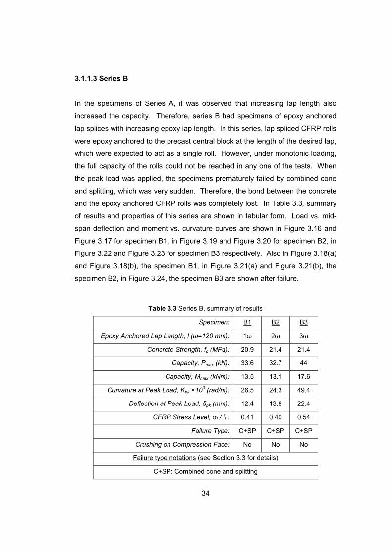
2.1.1.3 Series B...................................................................................... 12
2.1.1.4 Series C ..................................................................................... 14
2.1.2 Direct Pull-Out Specimens ................................................................ 16
2.1.2.1 Series D ..................................................................................... 16
2.2 Materials .................................................................................................. 19
2.2.1 Concrete ........................................................................................... 19

ix
2.2.2 Steel Reinforcement.......................................................................... 20
2.2.3 Carbon Fiber Reinforced Polymer ..................................................... 21
2.2.4 Epoxy................................................................................................ 21
2.3 Preparation of the Rolls............................................................................ 21
3. TEST SETUPS AND TEST RESULTS ..........................................................24
3.1 Beam Tests.............................................................................................. 24
3.1.1 Test Results ...................................................................................... 26
3.1.1.1 Reference Specimen CR............................................................ 26
3.1.1.2 Series A...................................................................................... 28
3.1.1.3 Series B...................................................................................... 34
3.1.1.4 Series C ..................................................................................... 40
3.2 Direct Pull-Out Tests................................................................................ 43
3.2.1 Test Results ...................................................................................... 44
3.2.1.1 Series D ..................................................................................... 45
3.3 Failure Types ........................................................................................... 49
3.3.1 Bar Slip ............................................................................................. 49
3.3.2 Cone Failure ..................................................................................... 49
3.3.3 Combined Cone Failure and Slip....................................................... 50
3.3.4 Combined Cone Failure and Splitting ................................................ 50
3.3.5 A General Comment.......................................................................... 51
4. DISCUSSION AND EVALUATION OF TEST RESULTS ...............................52
4.1 Discussion of the Beam Tests.................................................................. 52
4.1.1 Reference Specimen CR................................................................... 52
4.1.2 Series A ............................................................................................ 52
4.1.3 Series B ............................................................................................ 54
4.1.4 Series C ............................................................................................ 54
4.1.5 Comparison of Series A and Series B ............................................... 56
4.2 Discussion of Direct Pull-Out Tests .......................................................... 56
5. CONCLUSIONS AND RECOMMENDATIONS FOR FUTURE STUDIES ......58
5.1 Conclusions ............................................................................................. 58
5.1.1 Conclusions from Beam Tests........................................................... 58
5.1.2 Conclusions from Direct Pull-Out Tests............................................. 59

x
5.2 Recommendation for Future Studies........................................................ 60
REFERENCES ..................................................................................................62
APPENDICES
A. STRESS LEVEL............................................................................................63

xi
LIST OF TABLES TABLES
Table 2.1 Series A ............................................................................................. 11
Table 2.2 Series B ............................................................................................. 13
Table 2.3 Series C............................................................................................. 15
Table 2.4 Series D............................................................................................. 19
Table 2.5 Concrete mix design properties.......................................................... 20
Table 2.6 Test specimens.................................................................................. 20
Table 2.7 Steel reinforcement properties ........................................................... 20
Table 2.8 CFRP sheet properties....................................................................... 21
Table 3.1 Specimen CR, summary of results ..................................................... 26
Table 3.2 Series A, summary of results ............................................................. 29
Table 3.3 Series B, summary of results ............................................................. 34
Table 3.4 Series C, summary of results ............................................................. 41
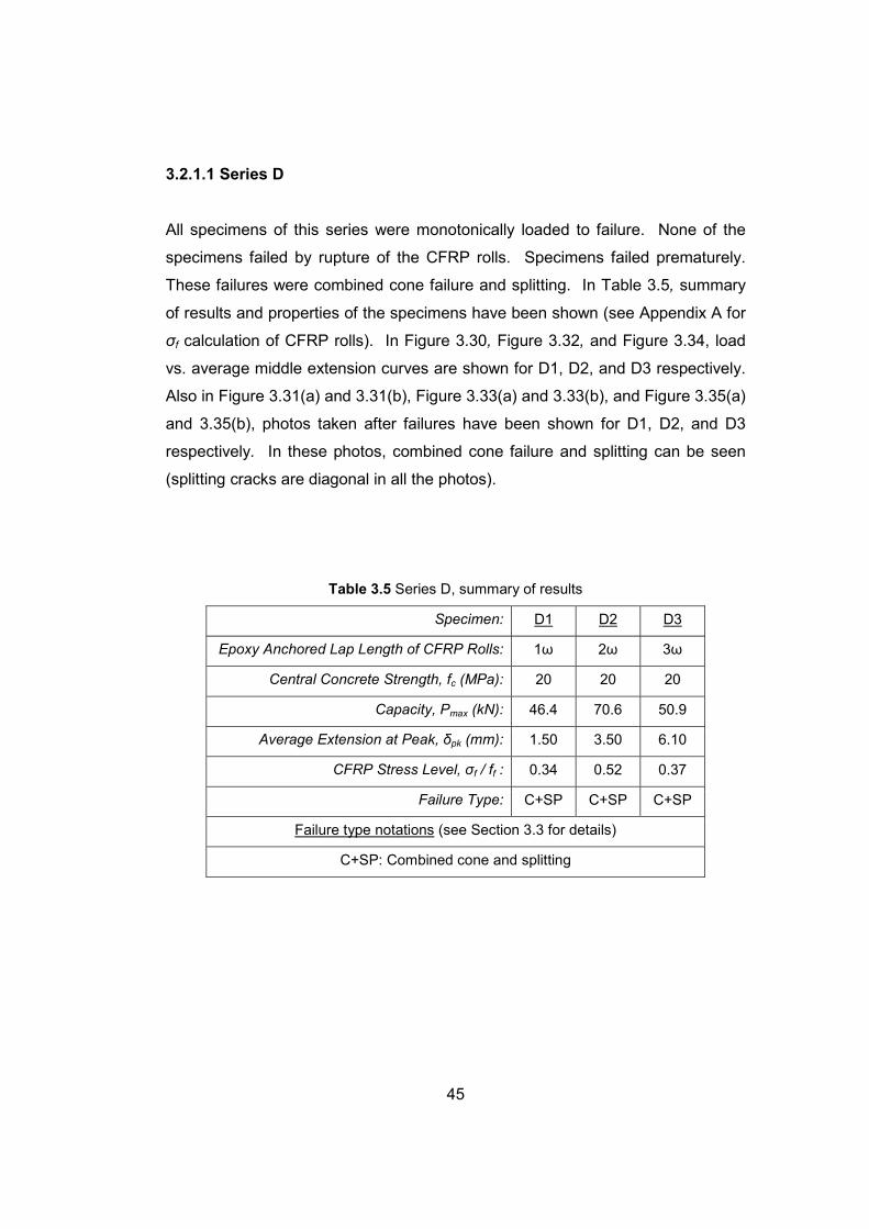
Table 3.5 Series D, summary of results ............................................................. 45
xii
LIST OF FIGURES
FIGURES
Figure 2.1 Reinforcement detail of the reference specimen .................................8
Figure 2.2 Section A-A from Figure 2.1................................................................9
Figure 2.3 Reinforcement detail of specimens in series A..................................11
Figure 2.4 (a) General view, (b) Top view of the lap splice (mid-span)...............12
Figure 2.5 Reinforcement detail of specimens in series B..................................13
Figure 2.6 (a) Anchorage, (b) Assembled with reinforcement ............................14
Figure 2.7 Reinforcement detail for series C......................................................15
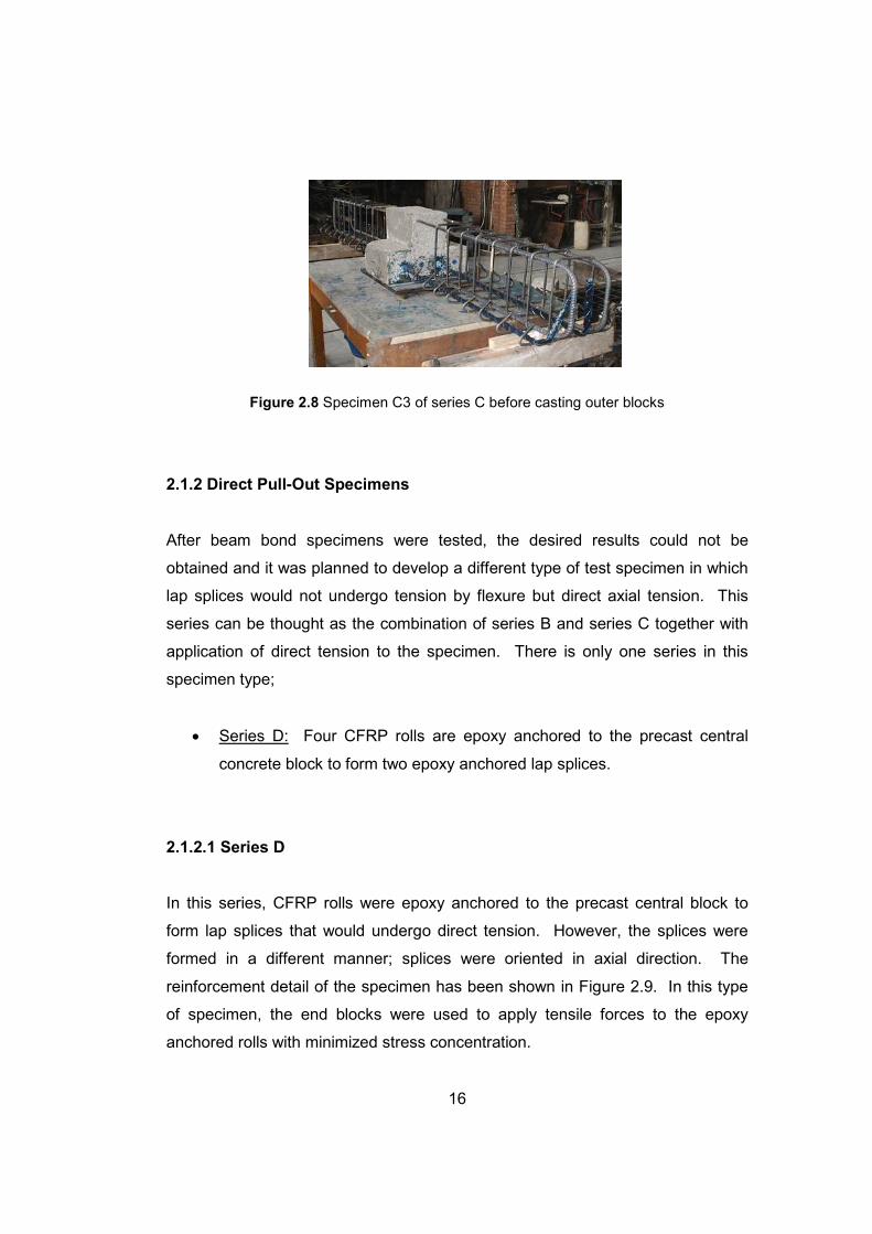
Figure 2.8 Specimen C3 of series C before casting outer blocks .......................16
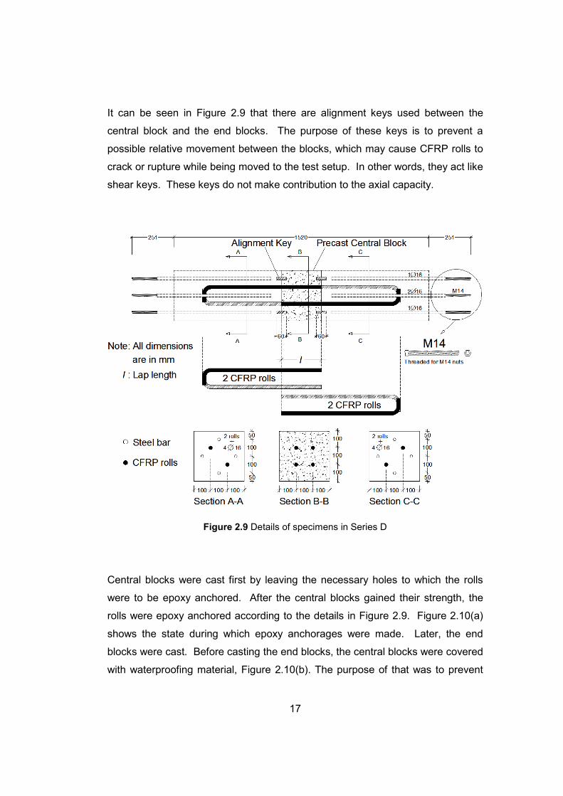
Figure 2.9 Details of specimens in Series D.......................................................17
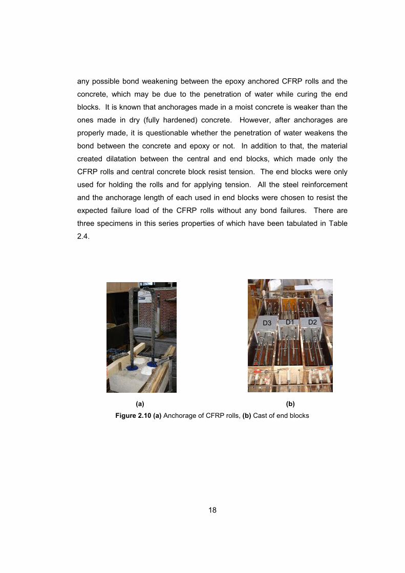
Figure 2.10 (a) Anchorage of CFRP rolls, (b) Cast of end blocks.......................18
Figure 2.11 Preparation of the rolls....................................................................23
Figure 2.12 CFRP rolls of Series D....................................................................23
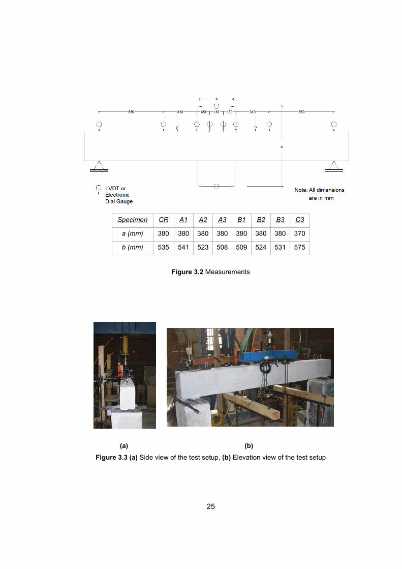
Figure 3.1 Test setup for beam specimens ........................................................24
Figure 3.2 Measurements ..................................................................................25
Figure 3.3 (a) Side view of the test setup, (b) Elevation view of the test setup ...25
Figure 3.4 Load vs. mid-span deflection curve of CR.........................................27
Figure 3.5 Moment vs. average curvature curve of CR ......................................27
Figure 3.6 Crack pattern of CR after failure........................................................28
Figure 3.7 Load vs. mid-span deflection curve of A1..........................................29
Figure 3.8 Moment vs. average curvature curve of A1.......................................30
Figure 3.9 Crack pattern of A1 after failure ........................................................30
Figure 3.10 Load vs. mid-span deflection curve of A2........................................31
Figure 3.11 Moment vs. average curvature curve of A2.....................................31
Figure 3.12 Crack pattern of A2 after failure ......................................................32
Figure 3.13 Load vs. mid-span deflection curve of A3........................................32
Figure 3.14 Moment vs. average curvature curve of A3.....................................33
Figure 3.15 Crack pattern of A3 after failure ......................................................33
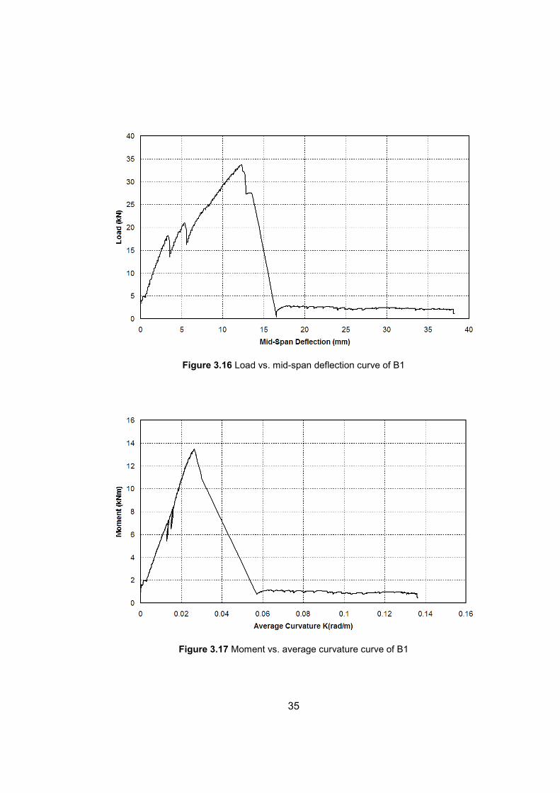
Figure 3.16 Load vs. mid-span deflection curve of B1........................................35
xiii
Figure 3.17 Moment vs. average curvature curve of B1.....................................35
Figure 3.18(a) Crack pattern of specimen B1 after failure ..................................36
Figure 3.18(b) Combined cone and splitting (B1)...............................................36
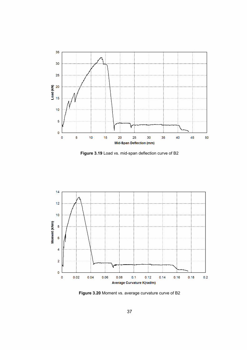
Figure 3.19 Load vs. mid-span deflection curve of B2........................................37
Figure 3.20 Moment vs. average curvature curve of B2.....................................37
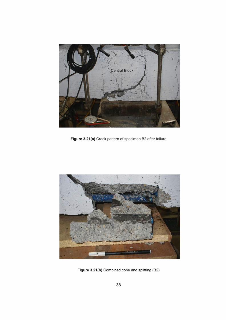
Figure 3.21(a) Crack pattern of specimen B2 after failure ..................................38
Figure 3.21(b) Combined cone and splitting (B2)...............................................38
Figure 3.22 Load vs. mid-span deflection curve of B3........................................39
Figure 3.23 Moment vs. average curvature curve of B3.....................................39
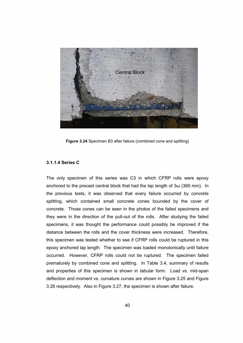
Figure 3.24 Specimen B3 after failure (combined cone and splitting).................40
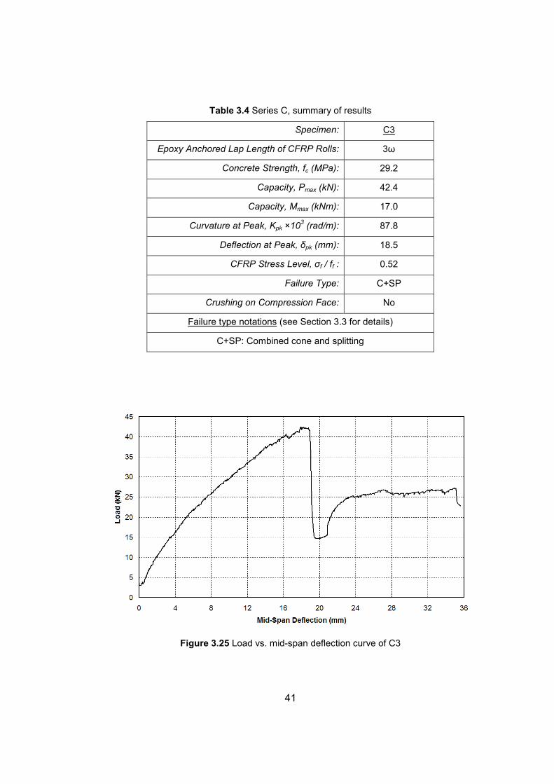
Figure 3.25 Load vs. mid-span deflection curve of C3 .......................................41
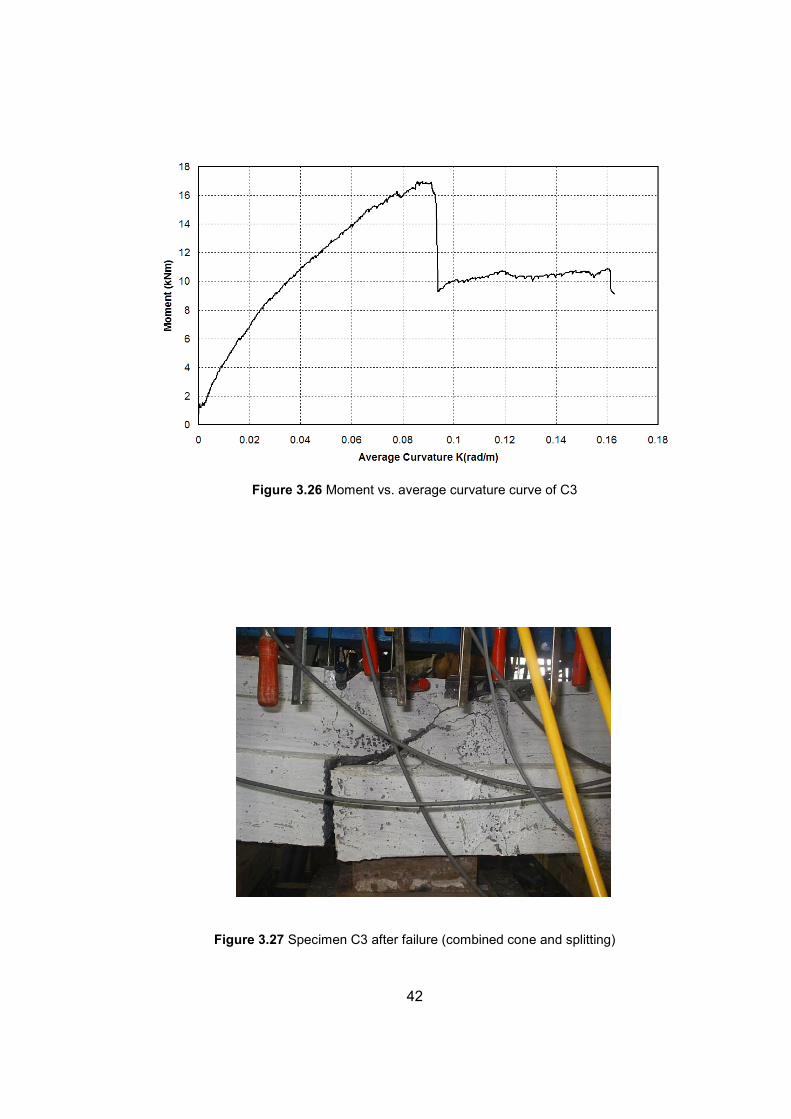
Figure 3.26 Moment vs. average curvature curve of C3.....................................42
Figure 3.27 Specimen C3 after failure (combined cone and splitting).................42
Figure 3.28 Test setup.......................................................................................43
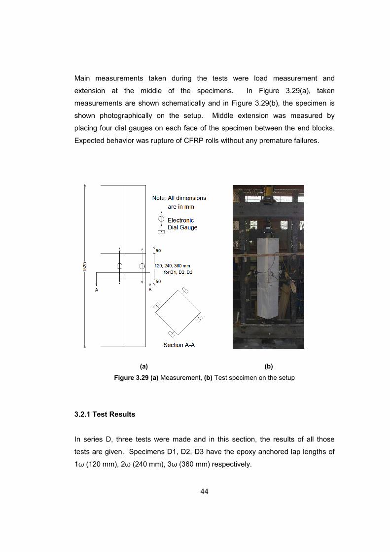
Figure 3.29 (a) Measurement, (b) Test specimen on the setup..........................44
Figure 3.30 Load vs. average middle extension curve of D1..............................46
Figure 3.31 (a) Failure D1, (b) Failure D1 ..........................................................46
Figure 3.32 Load vs. average middle extension curve of D2..............................47
Figure 3.33 (a) Failure D2, (b) Failure D2 ..........................................................47
Figure 3.34 Load vs. average middle extension curve of D3..............................48
Figure 3.35 (a) Failure D3, (b) Failure D3 (Sectional view) ................................48
Figure 3.36 Bar slip............................................................................................49
Figure 3.37 Cone failure ....................................................................................50
Figure 3.38 Combined cone failure and slip .......................................................50
Figure 3.39 Combined cone failure and splitting ................................................51
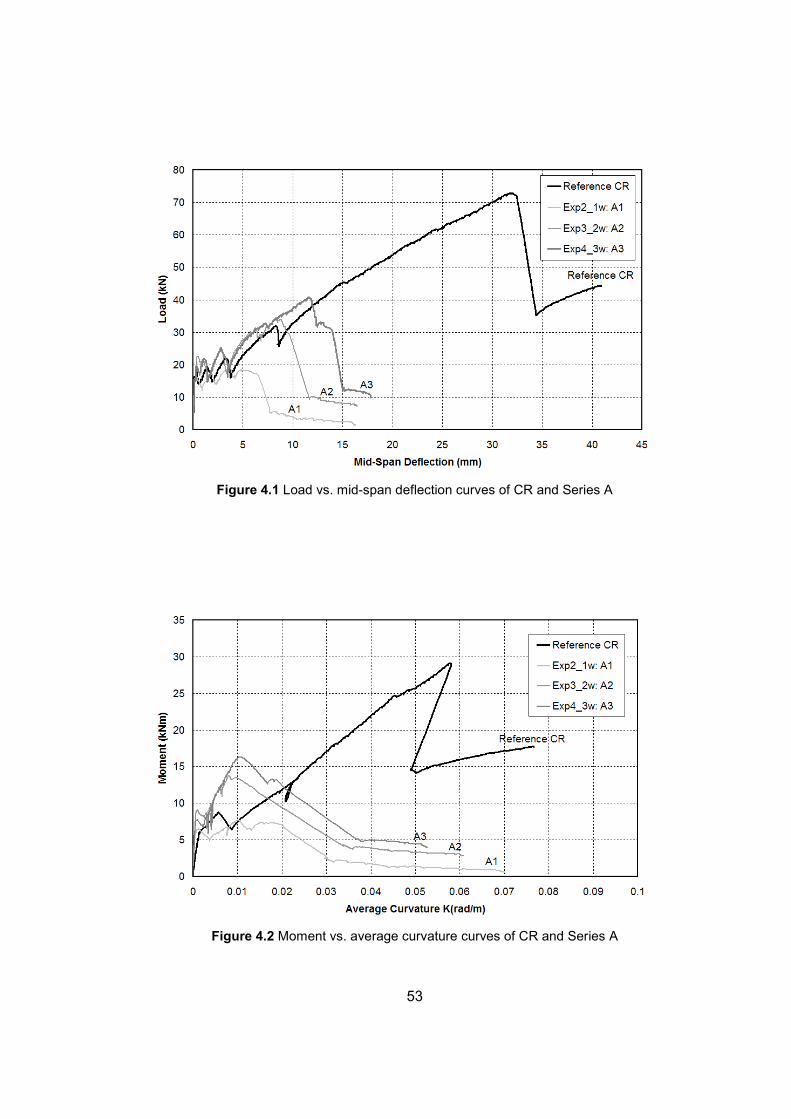
Figure 4.1 Load vs. mid-span deflection curves of CR and Series A..................53
Figure 4.2 Moment vs. average curvature curves of CR and Series A ...............53
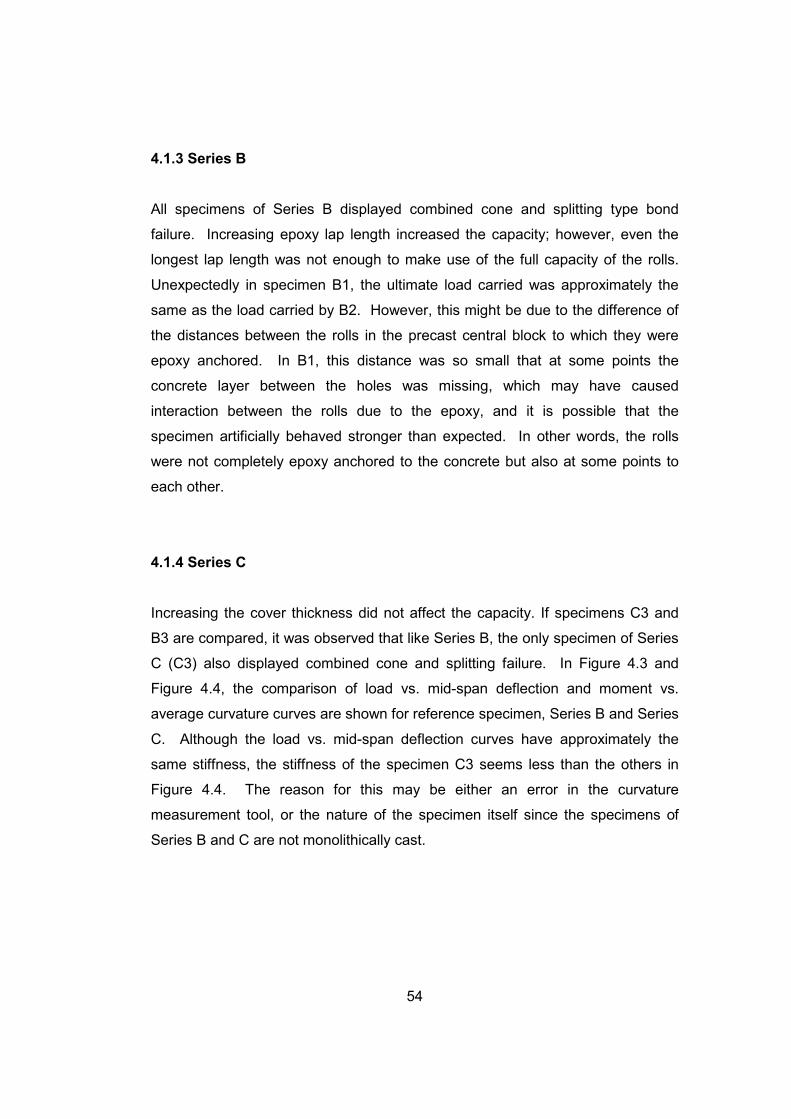
Figure 4.3 Load vs. mid-span deflection curves of CR, Series B, and Series C .55
Figure 4.4 Moment vs. average curvature curves of CR, Series B, and Series C
..........................................................................................................................55
Figure 4.5 Load vs. average extension curves of Series D ................................57
xiv
LIST OF SYMBOLS
φ Steel reinforcement diameter, mm
hφ Anchor hole diameter, mm
rφ Average roll diameter, mm
ykf Characteristic yield strength for steel, MPa
uf Ultimate strength for steel, MPa
ckf Characteristic compressive strength for concrete, MPa
cf Compressive strength for concrete (test specimens), MPa
ff Tensile strength for CFRP sheets, MPa
cuε Ultimate concrete strain, mm/mm
'ε Strain in compression reinforcement, mm/mm
CFRPy ,ε Ultimate strain for CFRP sheets, mm/mm
ω Width of CFRP sheets, mm
bω Balanced width of CFRP sheets, mm
t Thickness of CFRP sheets, mm
c Neutral axis depth, mm
wb Web thickness, mm
l Lap length, mm
L Length of the test specimen, mm
'σ Stress in compression reinforcement, MPa
fσ Stress developing in CFRP rolls, MPa
'F Force developing in compression reinforcement, kN
CFRPF Force developing in CFRP rolls, kN
maxP Maximum load capacity of the specimen, kN
maxM Moment capacity of the specimen, kNm

xv
pkK Curvature at peak load, rad/m
pkδ Deflection at peak load, mm
d Effective depth for tension reinforcement, mm
d ′ Effective depth for compression reinforcement, mm
1
CHAPTER 1
INTRODUCTION
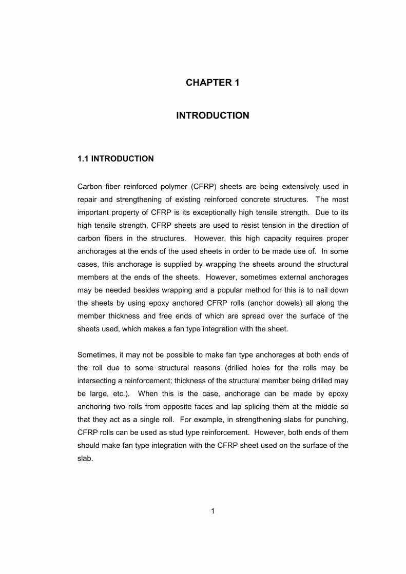
1.1 INTRODUCTION
Carbon fiber reinforced polymer (CFRP) sheets are being extensively used in
repair and strengthening of existing reinforced concrete structures. The most
important property of CFRP is its exceptionally high tensile strength. Due to its
high tensile strength, CFRP sheets are used to resist tension in the direction of
carbon fibers in the structures. However, this high capacity requires proper
anchorages at the ends of the used sheets in order to be made use of. In some
cases, this anchorage is supplied by wrapping the sheets around the structural
members at the ends of the sheets. However, sometimes external anchorages
may be needed besides wrapping and a popular method for this is to nail down
the sheets by using epoxy anchored CFRP rolls (anchor dowels) all along the
member thickness and free ends of which are spread over the surface of the
sheets used, which makes a fan type integration with the sheet.
Sometimes, it may not be possible to make fan type anchorages at both ends of
the roll due to some structural reasons (drilled holes for the rolls may be
intersecting a reinforcement; thickness of the structural member being drilled may
be large, etc.). When this is the case, anchorage can be made by epoxy
anchoring two rolls from opposite faces and lap splicing them at the middle so
that they act as a single roll. For example, in strengthening slabs for punching,
CFRP rolls can be used as stud type reinforcement. However, both ends of them
should make fan type integration with the CFRP sheet used on the surface of the
slab.

2
In the reported study, lap splice behavior and strength of CFRP rolls is
investigated by using flexural beam bond specimens, in which beams are
reinforced for flexure with CFRP rolls acting as tension reinforcement, and direct
pull-out specimens, in which the specimen is reinforced for tension with CFRP
rolls acting as direct tension reinforcement.
1.2 LITERATURE SURVEY
In literature, there is not much information on structural members reinforced with
CFRP rolls, although there are studies in which carbon solid rods have been
used as reinforcement.
Considering the advantage of exceptionally high strength of carbon fiber, it has
been proposed that CFRP rolls can be used to strengthen an existing structural
member as additional reinforcements in addition to their usage in anchoring
CFRP sheets.
[1] Erdoğan, H., “Improvement of Punching Behavior and Strength by CFRP
Rolls”. PhD thesis in progress, Department of Civil Engineering, Middle East
Technical University, Ankara, Turkey. In this study, full scale reinforced concrete
slabs that are reinforced for punching around column heads with CFRP rolls are
being tested. In this study, main parameter is the properties of the CFRP rolls
used in strengthening, such as width of the sheet used in forming the rolls,
orientations of the rolls on the slab, etc. This study is still in progress, but from
the results it can successfully be concluded that CFRP rolls can be used as stud
type punching reinforcement in strengthening slabs well.
[2] Gökdemir, H., “Seismic Strengthening of Beam-Column Joints in Existing R/C
Structures by using CFRP rolls”. PhD thesis in progress, Department of Civil
Engineering, Osmangazi University, Eskişehir, Turkey. In this study, different
reinforcement types are used for strengthening weak beam-column connections.
3
The study is still in progress at the METU Structural Mechanics Laboratory and
the object of the study is to develop the most efficient and economical
strengthening method for weak beam-column connections with minimum
disturbance in the connection zones. As the main part of this study, CFRP rolls
have been used as reinforcement in strengthening beam column joints, which
includes epoxy anchored lap splices. From that perspective, this study is directly
related to the study reported.
[3] Özdemir, G., “Mechanical Properties of CFRP Anchorages”, MSc thesis,
January 2005, Department of Civil Engineering, Middle East Technical University,
Ankara, Turkey. In this thesis, strength of CFRP anchor dowels is studied by
using pull-out specimens. Main parameters on the tensile strength capacity of
CFRP anchor dowels are the anchorage depth, anchorage diameter, and the
amount of fibers. This thesis suggests that there is a limit depth for increasing
the strength of anchor dowels beyond which depth; no bond strength gain can be
achieved as expected naturally. Moreover, it can be stated that the embedment
length depends not only on the properties of the anchor dowel itself but also on
the geometrical properties of the concrete body, such as the width of the concrete
member since the depth of a possible failure cone depends also on its maximum
possible base width, which depends on the area affected by the stresses
developing due to pull-out.
[4] Akın, E., “Strengthening of Brick Infilled Reinforced Concrete Frames with
CFRP Sheets”, PhD thesis in progress, Department of Civil Engineering, Middle
East Technical University, Ankara, Turkey. In this thesis, CFRP rolls are used as
anchor dowels to provide proper anchorages to the CFRP sheets used as
strengthening members. CFRP sheets are used as bracings in the frame, which
increases the lateral rigidity of the frame. However, these sheets should be
properly anchored to the existing structural members in order to behave
efficiently and this is achieved by wrapping the sheets around the columns and
then anchoring them with CFRP rolls (anchor dowels) to the existing structural
members. CFRP rolls are also used for anchoring the sheets used on the
4
opposite faces of the wall to each other. The test results show that using CFRP
sheets significantly enhances the behavior. However, anchorage is the most
important parameter since without proper anchorages; it will not be possible to
make use of the full capacity of the sheets.
1.3 OBJECT AND SCOPE OF THE STUDY
In testing CFRP rolls, the most important problem encountered is how to provide
proper end conditions with minimum amount of stress concentration at loading
zones. As it was stated previously, there are researches in which the behavior is
investigated with pull-out specimens. However, in those researches, there are
many premature failures, which can be attributed to the end conditions.
Therefore, this problem has to be minimized in order to obtain proper results and
it has been stated that this problem can be minimized by using specimens in
which loads are applied by making use of outer concrete blocks. Those blocks
cover the CFRP rolls so that they provide proper end conditions with minimum
stress concentration in the rolls, which makes it possible to test the rolls by
applying the load all along the roll length not at just one point on the rolls.
In the light of the explanation above, it was decided to have basically two types of
specimens in the research, which were flexural beam bond specimens and direct
pull-out specimens. However, before stating the details, a few definitions have to
be made.
1.3.1 Lap Length
There are two definitions for lap length, which are embedded lap length and
epoxy anchored lap length.
• Embedded Lap Length: it is used with its conventional definition, as the
minimum lap length for the ordinary lap splices embedded directly in
5
concrete, sufficient to make use of the full material capacity of the CFRP
rolls without any bond failure.
• Epoxy Anchored Lap Length: it is defined as the minimum lap length for
the splices formed by epoxy anchoring the rolls in hardened concrete,
sufficient to make use of the full material capacity of the rolls without any
bond failure.
1.3.2 The Object of the Study
The object of this study is to formulate an Epoxy Anchored Lap Length
expression in terms of the amount of the carbon fibers existing at the cross
section of the CFRP sheets used in shaping the rolls.
Although there are many factors affecting the behavior of the specimens, the
main parameter is the width (ω) of the CFRP sheet used in the rolls and it is
desired to formulate Epoxy Anchored Lap Length in terms of ω, like 2ω, 3ω etc.
to be used in engineering practice. There are two reasons in choosing the main
parameter as ω;
• Amount of carbon fibers at a CFRP sheet’s cross section can be
calculated by simply multiplying its width (ω) by its thickness (t).
• Used CFRP sheet type has carbon fibers oriented in the same direction
with a reference sheet thickness of 0.165 mm and the formulation will be
made by taking the sheet thickness constant since manufactured CFRP
sheets do not show variation in their thicknesses. However, if a different
thickness is reported by a manufacturer for a specific CFRP sheet, the
formulation can be modified by multiplying it with the ratio of the used
sheet thickness to the reference thickness (tused/tref).
6
CHAPTER 2
TEST SPECIMENS
2.1 TEST SPECIMENS
When the study was first initiated, test specimens were chosen as 200×300 (mm)
flexural beam bond specimens due to the debatable results obtained in simple
pull-out tests. Moreover, after testing the specimens, testing of another specimen
type was decided and they were direct pull-out specimens.
2.1.1 Flexural Beam Bond Specimens
The main idea in using these specimens was to create tensile forces in the CFRP
rolls without causing premature failures, which can be attributed to the stress
concentration developing at loading zones in simple pull-out tests. There are four
types of beam bond specimens;
• Reference specimen (CR): Reinforced for flexure with two continuous
CFRP rolls acting as tension reinforcement.
• Series A: Reinforced for flexure with directly embedded lap spliced CFRP
rolls at the mid-span.
• Series B: Reinforced for flexure with lap spliced CFRP rolls that are
epoxy anchored to the precast concrete block at the mid-span of the
beam.
• Series C: The same type as series B. However, this series has
increased cover thickness.
7
All of the specimens above were tested under two point loadings applied at 1/3rd
of the beam span (four point bending test) so that a zero shear and a constant
moment region was obtained at the mid-span.
2.1.1.1 Reference Specimen
The aim of lap splice is to make the lap spliced reinforcements act as a single
reinforcement. For this reason, the behavior of beams reinforced with continuous
CFRP rolls as tension reinforcements should be studied so that lap spliced cases
can be compared to the behavior of the reference specimen (CR).
In order to study CFRP rolls’ behavior well, tension failure must be ensured.
Therefore, determination of the amount of carbon fibers to be used in shaping the
rolls is essential so that the failure mode of the beam will not be a compression
failure, but it will be a tension failure. In other words, it should be under-
reinforced. Since the thickness of the sheets is constant (t=0.165mm), only the
strip width (ω) to be used has to be computed. The reinforcement detail of the
reference specimen has been shown in Figure 2.1.
In concrete sections that are reinforced with steel reinforcement, tension failure
refers to yielding of steel without crushing on compression face and since steel is
a ductile material, the failure is ductile. Tension failure stated in the paragraph
above refers to the rupture of CFRP rolls. Moreover, due to the nature of carbon
fibers, the tension failure stated is brittle, unlike steel reinforcement. Therefore, in
the paragraph above, “under-reinforced” refers to the failure of CFRP rolls rather
than ductile behavior.
8
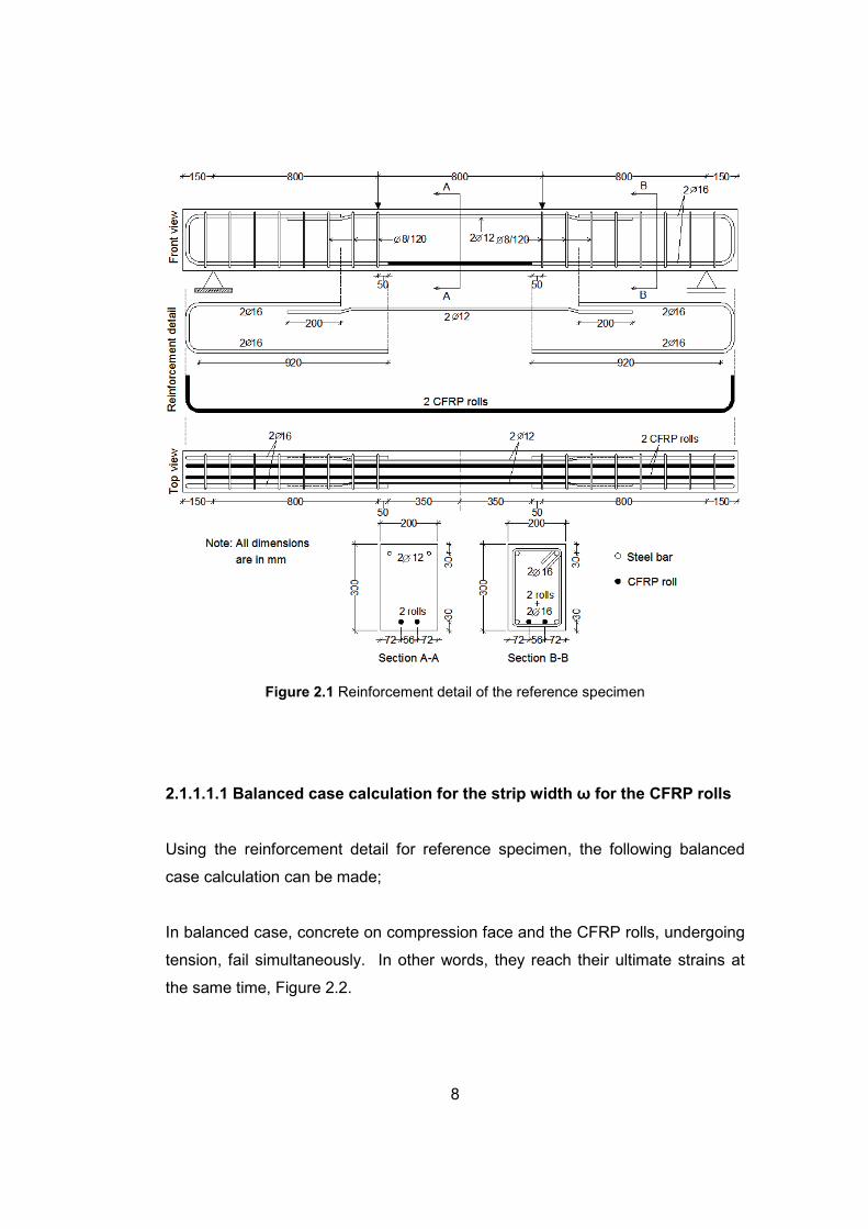
Figure 2.1 Reinforcement detail of the reference specimen
2.1.1.1.1 Balanced case calculation for the strip width ω for the CFRP rolls
Using the reinforcement detail for reference specimen, the following balanced
case calculation can be made;
In balanced case, concrete on compression face and the CFRP rolls, undergoing
tension, fail simultaneously. In other words, they reach their ultimate strains at
the same time, Figure 2.2.
9
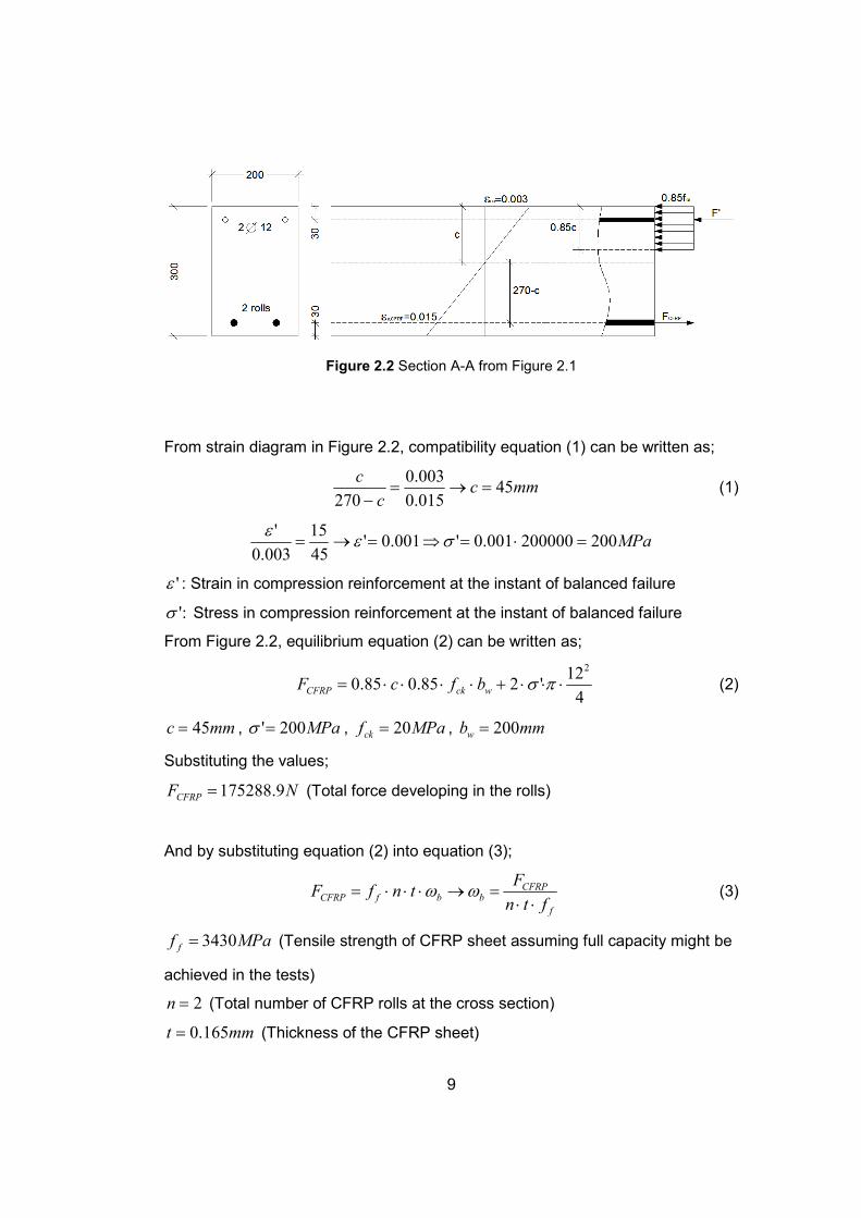
Figure 2.2 Section A-A from Figure 2.1
From strain diagram in Figure 2.2, compatibility equation (1) can be written as;
mmcc
c45
015.0
003.0
270=→=
− (1)
MPa200200000001.0'001.0'45
15
003.0
'=⋅=⇒=→= σε
ε
'ε : Strain in compression reinforcement at the instant of balanced failure
:'σ Stress in compression reinforcement at the instant of balanced failure
From Figure 2.2, equilibrium equation (2) can be written as;
4
12'285.085.0
2
⋅⋅⋅+⋅⋅⋅⋅= πσwckCFRP bfcF (2)
mmc 45= , MPa200'=σ , MPafck 20= , mmbw 200=
Substituting the values;
NFCFRP 9.175288= (Total force developing in the rolls)
And by substituting equation (2) into equation (3);
f
CFRPbbfCFRP
ftn
FtnfF
⋅⋅=→⋅⋅⋅= ωω (3)
MPaf f 3430= (Tensile strength of CFRP sheet assuming full capacity might be
achieved in the tests)
2=n (Total number of CFRP rolls at the cross section)
mmt 165.0= (Thickness of the CFRP sheet)
10
:bω Balanced width of the CFRP sheets
Substituting the values;
mmb 86.154=ω
The balanced CFRP strip width is calculated as 154.86 mm. Therefore, in order
to obtain an under-reinforced section, 120 mm of CFRP sheet, which is less than
ωb for each of the CFRP rolls, is chosen.
The strip width to be used is calculated as shown above and by using the stated
strip width, the rolls were prepared, which is explained in Section 2.3 of this
chapter.
2.1.1.2 Series A
In this series, behavior of the splices made by lap splicing two CFRP rolls at the
middle of the beam’s span has been studied. The main objective in this series
was to make the embedded lap spliced rolls act as a single roll and to make use
of the full material capacity of the rolls. In other words, lap spliced CFRP rolls
were expected to rupture without any premature failure.
The reinforcement detail is the same as the reference specimen except the lap
splices. The detail is shown in Figure 2.3. In this series, three specimens were
planned to be tested. In these specimens, the only changing parameter was the
lap length (l), which is embedded lap length, since a lap length formulation like
1ω, 2ω, etc is desired to be obtained. The parameters of the specimens are
tabulated with respect to the specimen names in Table 2.1. In that table, the
numbers next to the abbreviation letters for Series A stand for the multipliers of
strip width (ω).
11
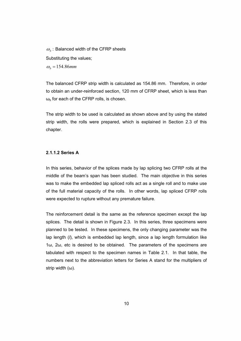
Table 2.1 Series A
Specimen Name Lap length (l)
A1 1ω = 120 mm
A2 2ω = 240 mm
A3 3ω = 360 mm
Figure 2.3 Reinforcement detail of specimens in series A
12
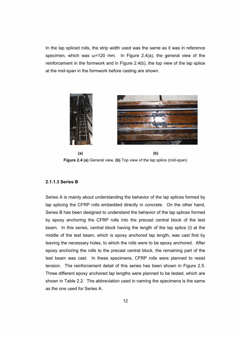
In the lap spliced rolls, the strip width used was the same as it was in reference
specimen, which was ω=120 mm. In Figure 2.4(a), the general view of the
reinforcement in the formwork and in Figure 2.4(b), the top view of the lap splice
at the mid-span in the formwork before casting are shown.
(a) (b)
Figure 2.4 (a) General view, (b) Top view of the lap splice (mid-span)
2.1.1.3 Series B
Series A is mainly about understanding the behavior of the lap splices formed by
lap splicing the CFRP rolls embedded directly in concrete. On the other hand,
Series B has been designed to understand the behavior of the lap splices formed
by epoxy anchoring the CFRP rolls into the precast central block of the test
beam. In this series, central block having the length of the lap splice (l) at the
middle of the test beam, which is epoxy anchored lap length, was cast first by
leaving the necessary holes, to which the rolls were to be epoxy anchored. After
epoxy anchoring the rolls to the precast central block, the remaining part of the
test beam was cast. In these specimens, CFRP rolls were planned to resist
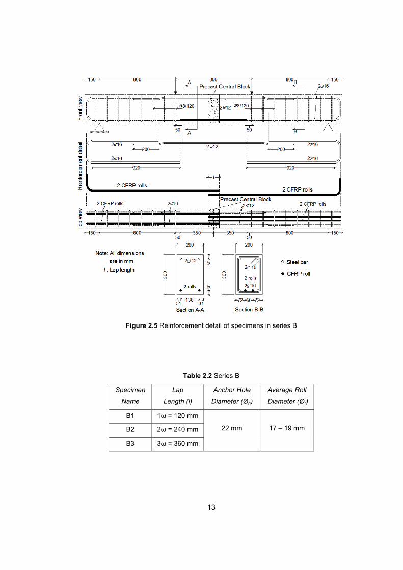
tension. The reinforcement detail of this series has been shown in Figure 2.5.
Three different epoxy anchored lap lengths were planned to be tested, which are
shown in Table 2.2. The abbreviation used in naming the specimens is the same
as the one used for Series A.
13
Figure 2.5 Reinforcement detail of specimens in series B
Table 2.2 Series B
Specimen
Name
Lap
Length (l)
Anchor Hole
Diameter (Øh)
Average Roll
Diameter (Ør)
B1 1ω = 120 mm
B2 2ω = 240 mm
B3 3ω = 360 mm
22 mm 17 – 19 mm
14
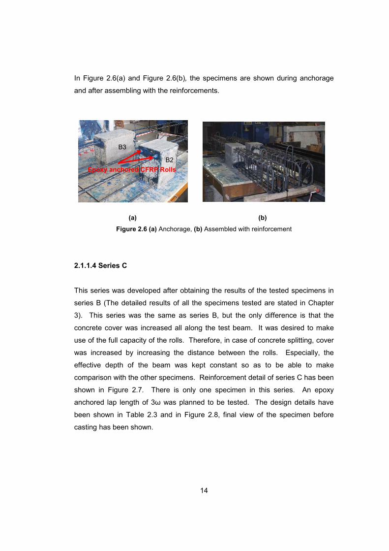
In Figure 2.6(a) and Figure 2.6(b), the specimens are shown during anchorage
and after assembling with the reinforcements.
(a) (b)
Figure 2.6 (a) Anchorage, (b) Assembled with reinforcement
2.1.1.4 Series C
This series was developed after obtaining the results of the tested specimens in
series B (The detailed results of all the specimens tested are stated in Chapter
3). This series was the same as series B, but the only difference is that the
concrete cover was increased all along the test beam. It was desired to make
use of the full capacity of the rolls. Therefore, in case of concrete splitting, cover
was increased by increasing the distance between the rolls. Especially, the
effective depth of the beam was kept constant so as to be able to make
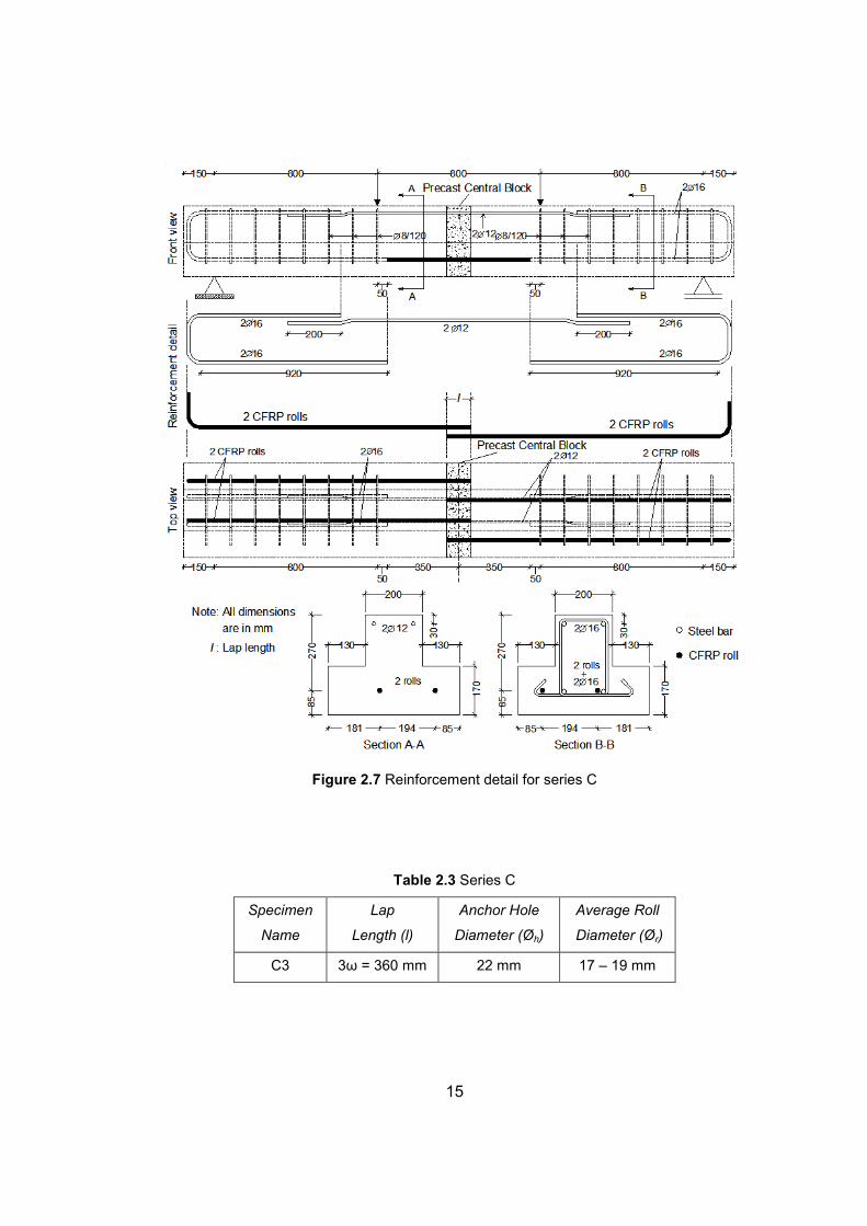
comparison with the other specimens. Reinforcement detail of series C has been
shown in Figure 2.7. There is only one specimen in this series. An epoxy
anchored lap length of 3ω was planned to be tested. The design details have
been shown in Table 2.3 and in Figure 2.8, final view of the specimen before
casting has been shown.
Epoxy anchored CFRP Rolls
B2
B3
15
Figure 2.7 Reinforcement detail for series C
Table 2.3 Series C
Specimen
Name
Lap
Length (l)
Anchor Hole
Diameter (Øh)
Average Roll
Diameter (Ør)
C3 3ω = 360 mm 22 mm 17 – 19 mm
16
Figure 2.8 Specimen C3 of series C before casting outer blocks
2.1.2 Direct Pull-Out Specimens
After beam bond specimens were tested, the desired results could not be
obtained and it was planned to develop a different type of test specimen in which
lap splices would not undergo tension by flexure but direct axial tension. This
series can be thought as the combination of series B and series C together with
application of direct tension to the specimen. There is only one series in this
specimen type;
• Series D: Four CFRP rolls are epoxy anchored to the precast central
concrete block to form two epoxy anchored lap splices.
2.1.2.1 Series D
In this series, CFRP rolls were epoxy anchored to the precast central block to
form lap splices that would undergo direct tension. However, the splices were
formed in a different manner; splices were oriented in axial direction. The
reinforcement detail of the specimen has been shown in Figure 2.9. In this type
of specimen, the end blocks were used to apply tensile forces to the epoxy
anchored rolls with minimized stress concentration.
17
It can be seen in Figure 2.9 that there are alignment keys used between the
central block and the end blocks. The purpose of these keys is to prevent a
possible relative movement between the blocks, which may cause CFRP rolls to
crack or rupture while being moved to the test setup. In other words, they act like
shear keys. These keys do not make contribution to the axial capacity.
Figure 2.9 Details of specimens in Series D
Central blocks were cast first by leaving the necessary holes to which the rolls
were to be epoxy anchored. After the central blocks gained their strength, the
rolls were epoxy anchored according to the details in Figure 2.9. Figure 2.10(a)
shows the state during which epoxy anchorages were made. Later, the end
blocks were cast. Before casting the end blocks, the central blocks were covered
with waterproofing material, Figure 2.10(b). The purpose of that was to prevent
18
any possible bond weakening between the epoxy anchored CFRP rolls and the
concrete, which may be due to the penetration of water while curing the end
blocks. It is known that anchorages made in a moist concrete is weaker than the
ones made in dry (fully hardened) concrete. However, after anchorages are
properly made, it is questionable whether the penetration of water weakens the
bond between the concrete and epoxy or not. In addition to that, the material
created dilatation between the central and end blocks, which made only the
CFRP rolls and central concrete block resist tension. The end blocks were only
used for holding the rolls and for applying tension. All the steel reinforcement
and the anchorage length of each used in end blocks were chosen to resist the
expected failure load of the CFRP rolls without any bond failures. There are
three specimens in this series properties of which have been tabulated in Table
2.4.
(a) (b)
Figure 2.10 (a) Anchorage of CFRP rolls, (b) Cast of end blocks
D3 D1 D2
19
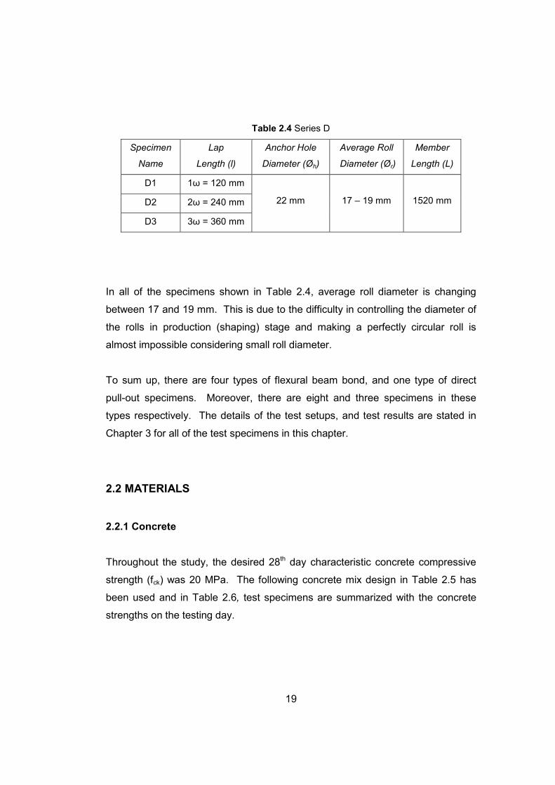
Table 2.4 Series D
Specimen
Name
Lap
Length (l)
Anchor Hole
Diameter (Øh)
Average Roll
Diameter (Ør)
Member
Length (L)
D1 1ω = 120 mm
D2 2ω = 240 mm
D3 3ω = 360 mm
22 mm 17 – 19 mm 1520 mm
In all of the specimens shown in Table 2.4, average roll diameter is changing
between 17 and 19 mm. This is due to the difficulty in controlling the diameter of
the rolls in production (shaping) stage and making a perfectly circular roll is
almost impossible considering small roll diameter.
To sum up, there are four types of flexural beam bond, and one type of direct
pull-out specimens. Moreover, there are eight and three specimens in these
types respectively. The details of the test setups, and test results are stated in
Chapter 3 for all of the test specimens in this chapter.
2.2 MATERIALS
2.2.1 Concrete
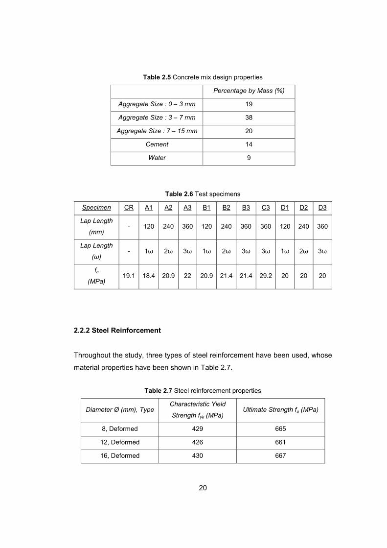
Throughout the study, the desired 28th day characteristic concrete compressive
strength (fck) was 20 MPa. The following concrete mix design in Table 2.5 has
been used and in Table 2.6, test specimens are summarized with the concrete
strengths on the testing day.
20
Table 2.5 Concrete mix design properties
Percentage by Mass (%)
Aggregate Size : 0 – 3 mm 19
Aggregate Size : 3 – 7 mm 38
Aggregate Size : 7 – 15 mm 20
Cement 14
Water 9
Table 2.6 Test specimens
Specimen CR A1 A2 A3 B1 B2 B3 C3 D1 D2 D3
Lap Length
(mm) - 120 240 360 120 240 360 360 120 240 360
Lap Length
(ω) - 1ω 2ω 3ω 1ω 2ω 3ω 3ω 1ω 2ω 3ω
fc
(MPa) 19.1 18.4 20.9 22 20.9 21.4 21.4 29.2 20 20 20
2.2.2 Steel Reinforcement
Throughout the study, three types of steel reinforcement have been used, whose
material properties have been shown in Table 2.7.
Table 2.7 Steel reinforcement properties
Diameter Ø (mm), Type Characteristic Yield
Strength fyk (MPa) Ultimate Strength fu (MPa)
8, Deformed 429 665
12, Deformed 426 661
16, Deformed 430 667
21
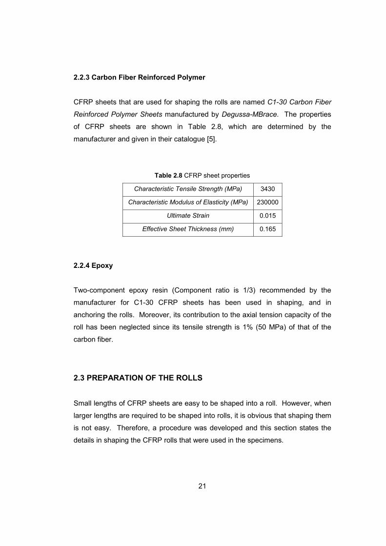
2.2.3 Carbon Fiber Reinforced Polymer
CFRP sheets that are used for shaping the rolls are named C1-30 Carbon Fiber
Reinforced Polymer Sheets manufactured by Degussa-MBrace. The properties
of CFRP sheets are shown in Table 2.8, which are determined by the
manufacturer and given in their catalogue [5].
Table 2.8 CFRP sheet properties
Characteristic Tensile Strength (MPa) 3430
Characteristic Modulus of Elasticity (MPa) 230000
Ultimate Strain 0.015
Effective Sheet Thickness (mm) 0.165
2.2.4 Epoxy
Two-component epoxy resin (Component ratio is 1/3) recommended by the
manufacturer for C1-30 CFRP sheets has been used in shaping, and in
anchoring the rolls. Moreover, its contribution to the axial tension capacity of the
roll has been neglected since its tensile strength is 1% (50 MPa) of that of the
carbon fiber.
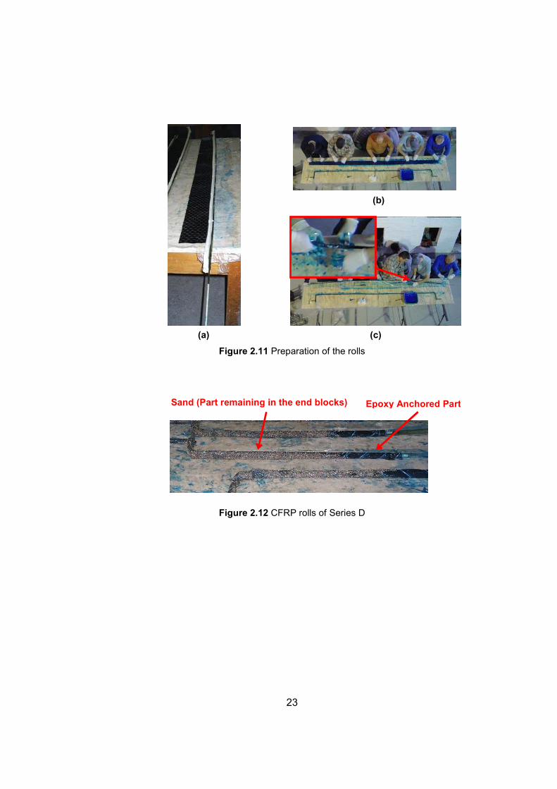
2.3 PREPARATION OF THE ROLLS
Small lengths of CFRP sheets are easy to be shaped into a roll. However, when
larger lengths are required to be shaped into rolls, it is obvious that shaping them
is not easy. Therefore, a procedure was developed and this section states the
details in shaping the CFRP rolls that were used in the specimens.

22
In this procedure, the aim is to make CFRP rolls, which will not contain any other
materials contributing to the tensile capacity apart from the CFRP sheet itself.
Also, the resulting rolls must be capable of being bent at the designated locations
for anchorage purposes. Considering those, the procedure used is summarized
as follows;
• A straight steel bar of 4 mm diameter at the required length is cut.
• The steel bar is then greased for easy pull out after the CFRP roll is
prepared.
• The greased bar is then wrapped by nylon.
• CFRP sheet to be used in the rolls is then attached to the bar that is
wrapped by nylon (Figure 2.11(a)).
• Two-component epoxy resin is prepared according to the instructions of
the manufacturer and spread on both surfaces of the CFRP sheet. Then,
it is rolled around the axis of the steel bar with some help (Figure 2.11(b)).
• After rolling is completed, the resulting roll is wrapped gently by a thread
in order to prevent opening of the roll after steel is taken out (Figure
2.11(c)).
• After the entire roll is wrapped, the steel inside the roll can be taken out
easily without disturbing the straightness of the roll.
• Finally, the required hooks can be bent for anchorage purposes. Figure
2.11(b) contains a completed roll that has bent hooks stated.
The same procedure was applied for the specimens of Series D (Direct pull-out
specimens). However, the part of the rolls which stayed in the end blocks was
covered with sand right after rolling was completed, while epoxy was still fresh,
so that the anchorage in the end blocks was improved in addition to bent hooks
(Figure 2.12). Since the tensile force was applied by concrete, any gain in
anchorage of the rolls to the end blocks was desirable in order to transfer the
tensile force well.
23
(b)
(a) (c)
Figure 2.11 Preparation of the rolls
Figure 2.12 CFRP rolls of Series D
Sand (Part remaining in the end blocks) Epoxy Anchored Part
24
CHAPTER 3
TEST SETUPS AND TEST RESULTS
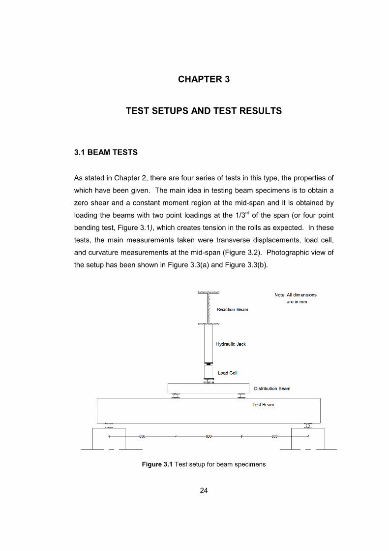
3.1 BEAM TESTS
As stated in Chapter 2, there are four series of tests in this type, the properties of
which have been given. The main idea in testing beam specimens is to obtain a
zero shear and a constant moment region at the mid-span and it is obtained by
loading the beams with two point loadings at the 1/3rd of the span (or four point
bending test, Figure 3.1), which creates tension in the rolls as expected. In these
tests, the main measurements taken were transverse displacements, load cell,
and curvature measurements at the mid-span (Figure 3.2). Photographic view of
the setup has been shown in Figure 3.3(a) and Figure 3.3(b).
Figure 3.1 Test setup for beam specimens
25
Specimen CR A1 A2 A3 B1 B2 B3 C3
a (mm) 380 380 380 380 380 380 380 370
b (mm) 535 541 523 508 509 524 531 575
Figure 3.2 Measurements
(a) (b)
Figure 3.3 (a) Side view of the test setup, (b) Elevation view of the test setup

26
3.1.1 Test Results
As stated previously, there are eight beam specimens, which were tested by
using the test setup shown. In this section, the results of those tests are given.
The main readings taken were the deflection at the mid-span, and the load
measurement taken by the load cell shown in test setup as well as the average
curvature measurement. In the following sections, test results of each series of
beam specimens are given.
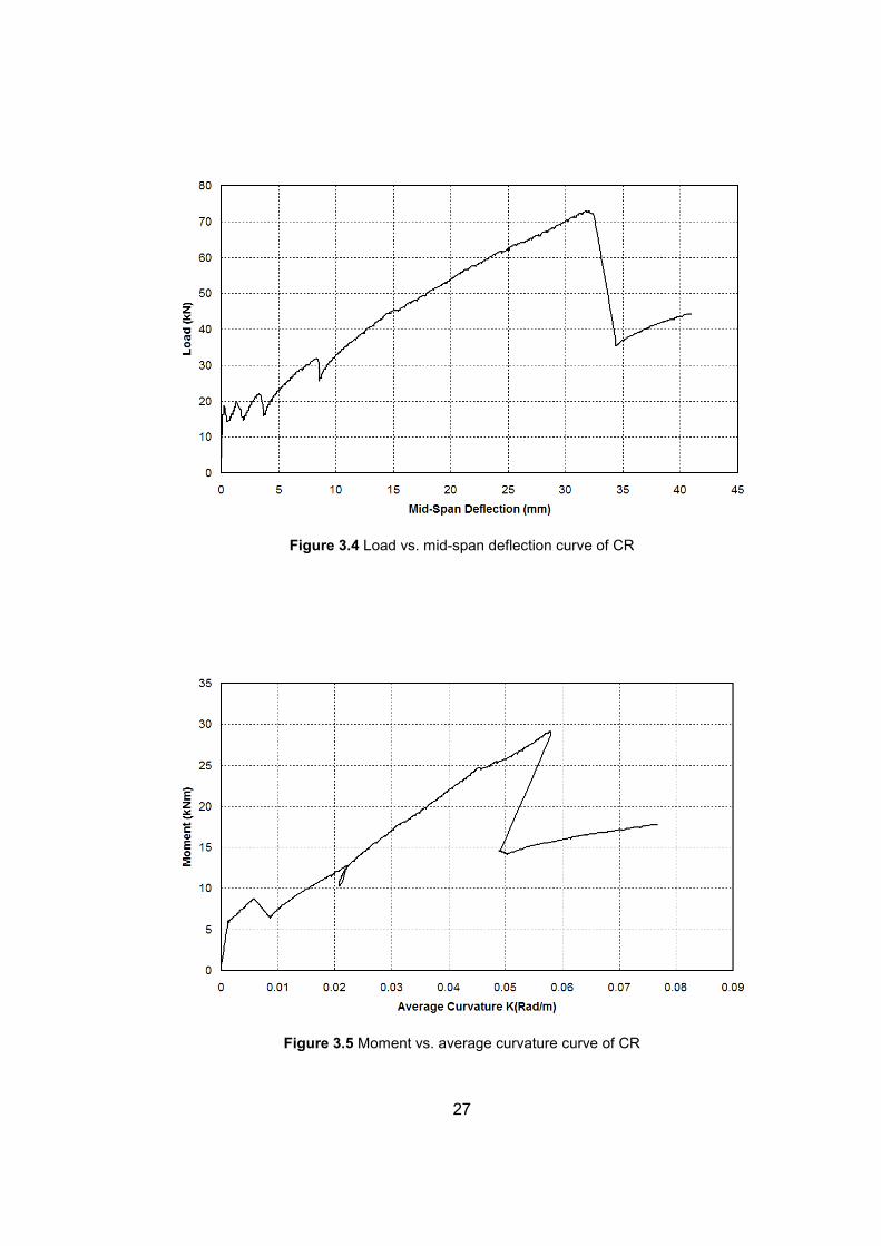
3.1.1.1 Reference Specimen CR
Specimen was monotonically loaded until CFRP ruptured. At the ultimate stage,
only one of the rolls ruptured, which was very sudden due to the perfectly linear
behavior of CFRP. In Table 3.1, summary of results and properties of this
specimen is shown in tabular form (see Appendix A for σf calculation of CFRP
rolls). Load vs. mid-span deflection and moment vs. curvature curves are shown
in Figure 3.4 and Figure 3.5 respectively. Also in Figure 3.6, the specimen is
shown after the failure.
Table 3.1 Specimen CR, summary of results
Tensile Reinforcement Type: Two continuous CFRP rolls
Concrete Strength, fc (MPa): 19.1
Capacity, Pmax (kN): 72.8
Capacity, Mmax (kNm): 29.1
Curvature at Peak Load, Kpk ×103 (rad/m): 58
Deflection at Peak Load, δpk (mm): 31.9
CFRP Stress Level, σf / ff : 0.92
Failure Type: CFRP rupture
Crushing on Compression Face: No
27
Figure 3.4 Load vs. mid-span deflection curve of CR
Figure 3.5 Moment vs. average curvature curve of CR
28
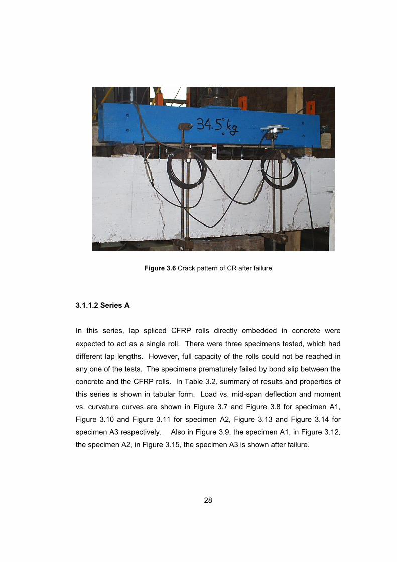
Figure 3.6 Crack pattern of CR after failure
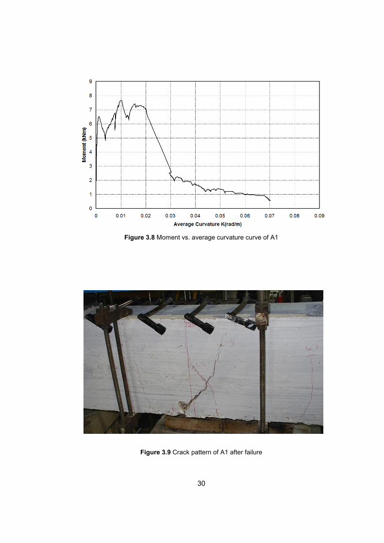
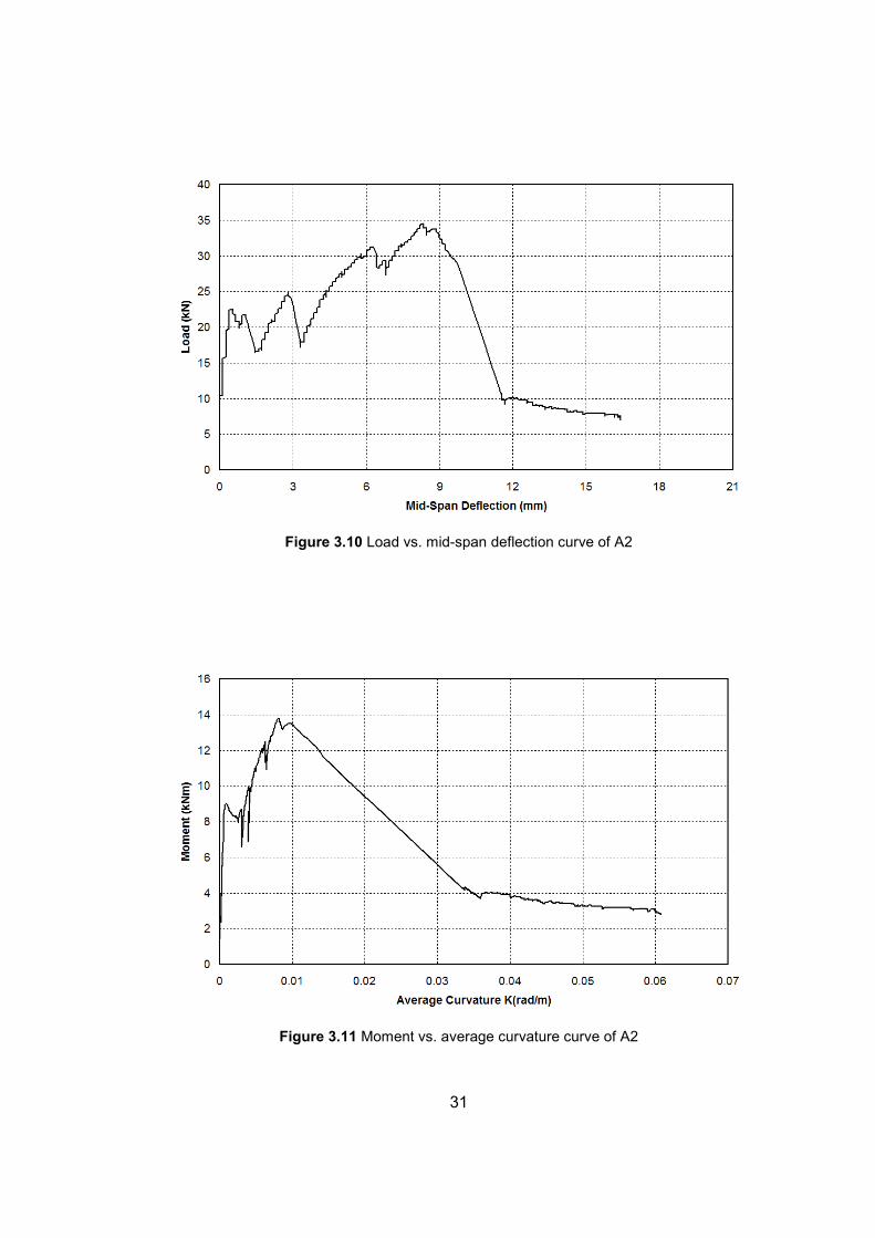
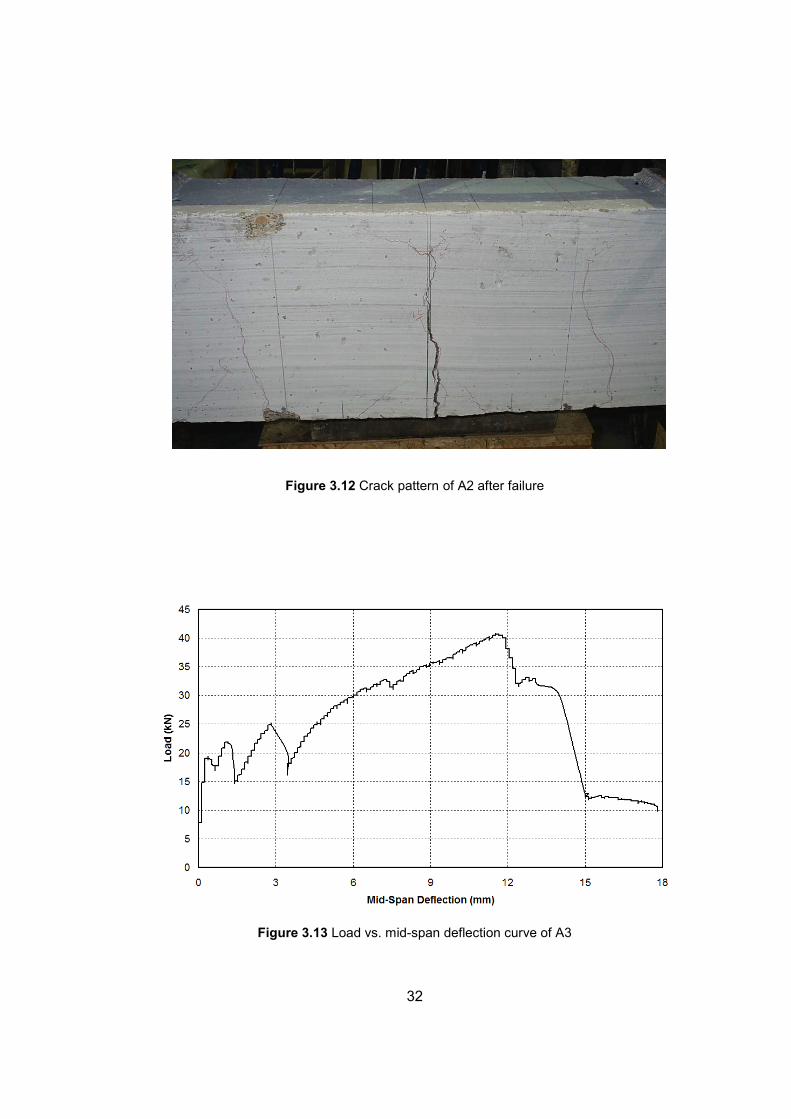
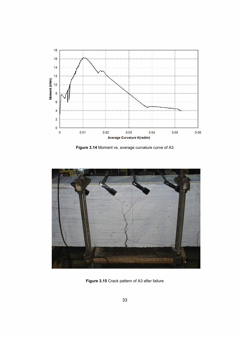
3.1.1.2 Series A
In this series, lap spliced CFRP rolls directly embedded in concrete were
expected to act as a single roll. There were three specimens tested, which had
different lap lengths. However, full capacity of the rolls could not be reached in
any one of the tests. The specimens prematurely failed by bond slip between the
concrete and the CFRP rolls. In Table 3.2, summary of results and properties of
this series is shown in tabular form. Load vs. mid-span deflection and moment
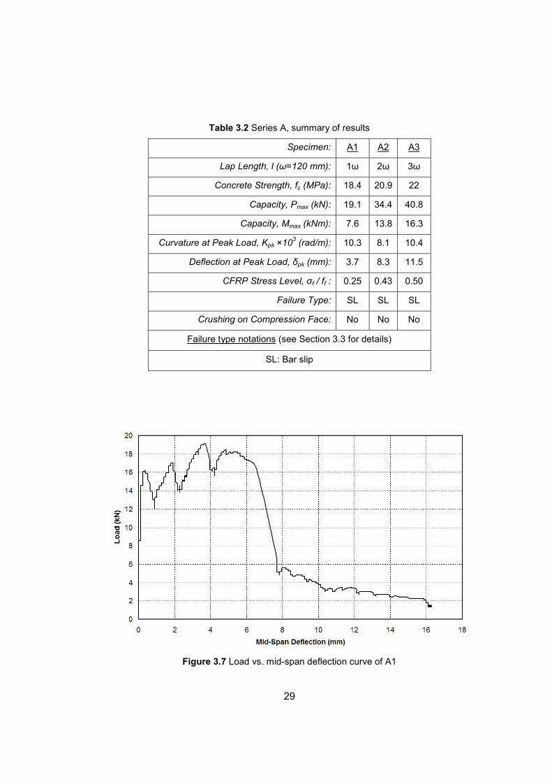
vs. curvature curves are shown in Figure 3.7 and Figure 3.8 for specimen A1,
Figure 3.10 and Figure 3.11 for specimen A2, Figure 3.13 and Figure 3.14 for
specimen A3 respectively. Also in Figure 3.9, the specimen A1, in Figure 3.12,
the specimen A2, in Figure 3.15, the specimen A3 is shown after failure.
29
Table 3.2 Series A, summary of results
Specimen: A1 A2 A3
Lap Length, l (ω=120 mm): 1ω 2ω 3ω
Concrete Strength, fc (MPa): 18.4 20.9 22
Capacity, Pmax (kN): 19.1 34.4 40.8
Capacity, Mmax (kNm): 7.6 13.8 16.3
Curvature at Peak Load, Kpk ×103 (rad/m): 10.3 8.1 10.4
Deflection at Peak Load, δpk (mm): 3.7 8.3 11.5
CFRP Stress Level, σf / ff : 0.25 0.43 0.50
Failure Type: SL SL SL
Crushing on Compression Face: No No No
Failure type notations (see Section 3.3 for details)
SL: Bar slip
Figure 3.7 Load vs. mid-span deflection curve of A1
30
Figure 3.8 Moment vs. average curvature curve of A1
Figure 3.9 Crack pattern of A1 after failure
31
Figure 3.10 Load vs. mid-span deflection curve of A2
Figure 3.11 Moment vs. average curvature curve of A2
32
Figure 3.12 Crack pattern of A2 after failure
Figure 3.13 Load vs. mid-span deflection curve of A3
33
Figure 3.14 Moment vs. average curvature curve of A3
Figure 3.15 Crack pattern of A3 after failure
34
3.1.1.3 Series B
In the specimens of Series A, it was observed that increasing lap length also
increased the capacity. Therefore, series B had specimens of epoxy anchored
lap splices with increasing epoxy lap length. In this series, lap spliced CFRP rolls
were epoxy anchored to the precast central block at the length of the desired lap,
which were expected to act as a single roll. However, under monotonic loading,
the full capacity of the rolls could not be reached in any one of the tests. When
the peak load was applied, the specimens prematurely failed by combined cone
and splitting, which was very sudden. Therefore, the bond between the concrete
and the epoxy anchored CFRP rolls was completely lost. In Table 3.3, summary
of results and properties of this series are shown in tabular form. Load vs. mid-
span deflection and moment vs. curvature curves are shown in Figure 3.16 and
Figure 3.17 for specimen B1, in Figure 3.19 and Figure 3.20 for specimen B2, in
Figure 3.22 and Figure 3.23 for specimen B3 respectively. Also in Figure 3.18(a)
and Figure 3.18(b), the specimen B1, in Figure 3.21(a) and Figure 3.21(b), the
specimen B2, in Figure 3.24, the specimen B3 are shown after failure.
Table 3.3 Series B, summary of results
Specimen: B1 B2 B3
Epoxy Anchored Lap Length, l (ω=120 mm): 1ω 2ω 3ω
Concrete Strength, fc (MPa): 20.9 21.4 21.4
Capacity, Pmax (kN): 33.6 32.7 44
Capacity, Mmax (kNm): 13.5 13.1 17.6
Curvature at Peak Load, Kpk ×103 (rad/m): 26.5 24.3 49.4
Deflection at Peak Load, δpk (mm): 12.4 13.8 22.4
CFRP Stress Level, σf / ff : 0.41 0.40 0.54
Failure Type: C+SP C+SP C+SP
Crushing on Compression Face: No No No
Failure type notations (see Section 3.3 for details)
C+SP: Combined cone and splitting
35
Figure 3.16 Load vs. mid-span deflection curve of B1
Figure 3.17 Moment vs. average curvature curve of B1

36
Figure 3.18(a) Crack pattern of specimen B1 after failure
Figure 3.18(b) Combined cone and splitting (B1)
Central Block
37
Figure 3.19 Load vs. mid-span deflection curve of B2
Figure 3.20 Moment vs. average curvature curve of B2
38
Figure 3.21(a) Crack pattern of specimen B2 after failure
Figure 3.21(b) Combined cone and splitting (B2)
Central Block

39
Figure 3.22 Load vs. mid-span deflection curve of B3
Figure 3.23 Moment vs. average curvature curve of B3
40
Figure 3.24 Specimen B3 after failure (combined cone and splitting)
3.1.1.4 Series C
The only specimen of this series was C3 in which CFRP rolls were epoxy
anchored to the precast central block that had the lap length of 3ω (360 mm). In
the previous tests, it was observed that every failure occurred by concrete
splitting, which contained small concrete cones bounded by the cover of
concrete. Those cones can be seen in the photos of the failed specimens and
they were in the direction of the pull-out of the rolls. After studying the failed
specimens, it was thought the performance could possibly be improved if the
distance between the rolls and the cover thickness were increased. Therefore,
this specimen was tested whether to see if CFRP rolls could be ruptured in this
epoxy anchored lap length. The specimen was loaded monotonically until failure
occurred. However, CFRP rolls could not be ruptured. The specimen failed
prematurely by combined cone and splitting. In Table 3.4, summary of results
and properties of this specimen is shown in tabular form. Load vs. mid-span
deflection and moment vs. curvature curves are shown in Figure 3.25 and Figure
3.26 respectively. Also in Figure 3.27, the specimen is shown after failure.
Central Block
41
Table 3.4 Series C, summary of results
Specimen: C3
Epoxy Anchored Lap Length of CFRP Rolls: 3ω
Concrete Strength, fc (MPa): 29.2
Capacity, Pmax (kN): 42.4
Capacity, Mmax (kNm): 17.0
Curvature at Peak, Kpk ×103 (rad/m): 87.8
Deflection at Peak, δpk (mm): 18.5
CFRP Stress Level, σf / ff : 0.52
Failure Type: C+SP
Crushing on Compression Face: No
Failure type notations (see Section 3.3 for details)
C+SP: Combined cone and splitting
Figure 3.25 Load vs. mid-span deflection curve of C3
42
Figure 3.26 Moment vs. average curvature curve of C3
Figure 3.27 Specimen C3 after failure (combined cone and splitting)

43
3.2 DIRECT PULL-OUT TESTS
There were only one series of test in this type of test specimen, which was Series
D. In this series, the main idea was application of tension directly to the central
block, unlike beam specimens. Details of this type of test specimen have been
given in Chapter 2. In Figure 3.28, test setup of this type is shown.
Figure 3.28 Test setup
44
Main measurements taken during the tests were load measurement and
extension at the middle of the specimens. In Figure 3.29(a), taken
measurements are shown schematically and in Figure 3.29(b), the specimen is
shown photographically on the setup. Middle extension was measured by
placing four dial gauges on each face of the specimen between the end blocks.
Expected behavior was rupture of CFRP rolls without any premature failures.
(a) (b)
Figure 3.29 (a) Measurement, (b) Test specimen on the setup
3.2.1 Test Results
In series D, three tests were made and in this section, the results of all those
tests are given. Specimens D1, D2, D3 have the epoxy anchored lap lengths of
1ω (120 mm), 2ω (240 mm), 3ω (360 mm) respectively.
45
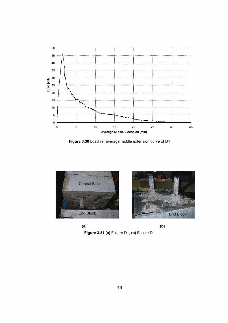
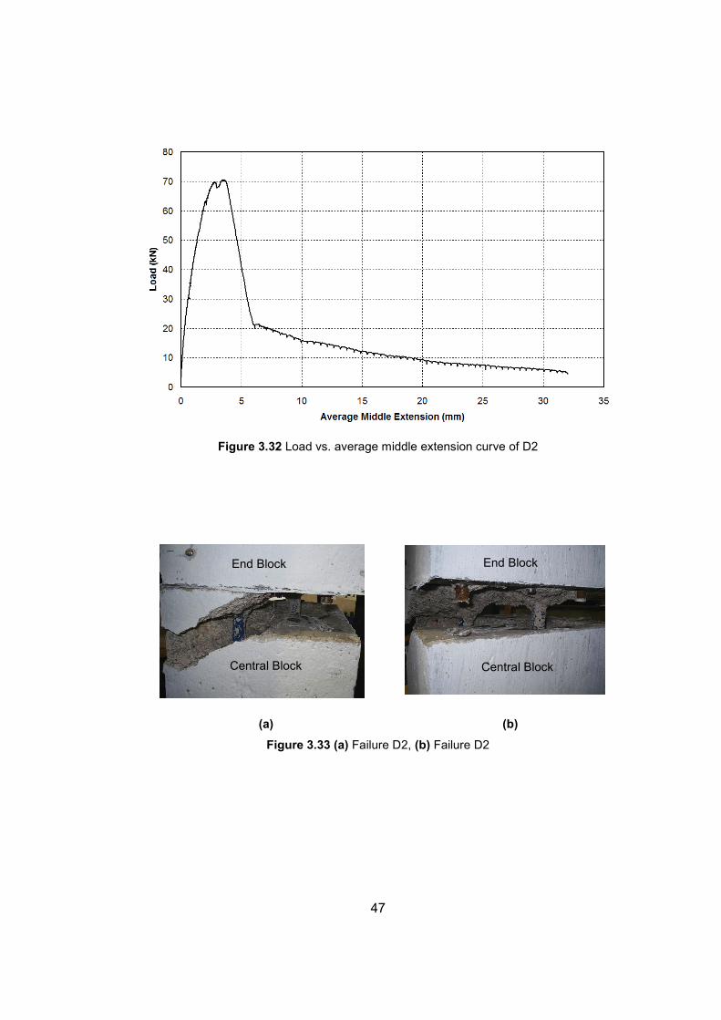
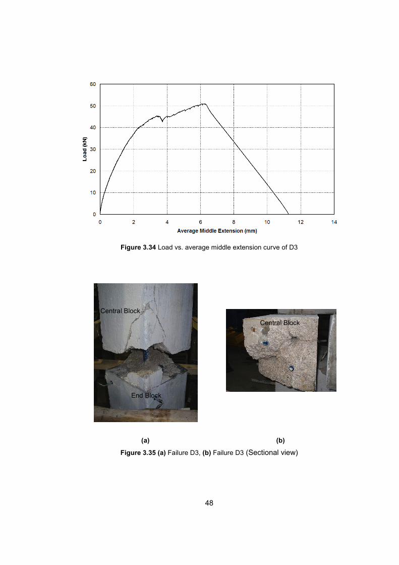
3.2.1.1 Series D
All specimens of this series were monotonically loaded to failure. None of the
specimens failed by rupture of the CFRP rolls. Specimens failed prematurely.
These failures were combined cone failure and splitting. In Table 3.5, summary
of results and properties of the specimens have been shown (see Appendix A for
σf calculation of CFRP rolls). In Figure 3.30, Figure 3.32, and Figure 3.34, load
vs. average middle extension curves are shown for D1, D2, and D3 respectively.
Also in Figure 3.31(a) and 3.31(b), Figure 3.33(a) and 3.33(b), and Figure 3.35(a)
and 3.35(b), photos taken after failures have been shown for D1, D2, and D3
respectively. In these photos, combined cone failure and splitting can be seen
(splitting cracks are diagonal in all the photos).
Table 3.5 Series D, summary of results
Specimen: D1 D2 D3
Epoxy Anchored Lap Length of CFRP Rolls: 1ω 2ω 3ω
Central Concrete Strength, fc (MPa): 20 20 20
Capacity, Pmax (kN): 46.4 70.6 50.9
Average Extension at Peak, δpk (mm): 1.50 3.50 6.10
CFRP Stress Level, σf / ff : 0.34 0.52 0.37
Failure Type: C+SP C+SP C+SP
Failure type notations (see Section 3.3 for details)
C+SP: Combined cone and splitting
46
Figure 3.30 Load vs. average middle extension curve of D1
(a) (b)
Figure 3.31 (a) Failure D1, (b) Failure D1
Central Block
End Block End Block
47
Figure 3.32 Load vs. average middle extension curve of D2
(a) (b)
Figure 3.33 (a) Failure D2, (b) Failure D2
Central Block
End Block
Central Block
End Block
48
Figure 3.34 Load vs. average middle extension curve of D3
(a) (b)
Figure 3.35 (a) Failure D3, (b) Failure D3 (Sectional view)
Central Block
End Block
Central Block
49
3.3 FAILURE TYPES
Besides the natural and desirable failure type, i.e. CFRP rupture, there are four
possible bond failure types one can suggest for CFRP roll anchorage. These
four possibilities are briefly explained below:
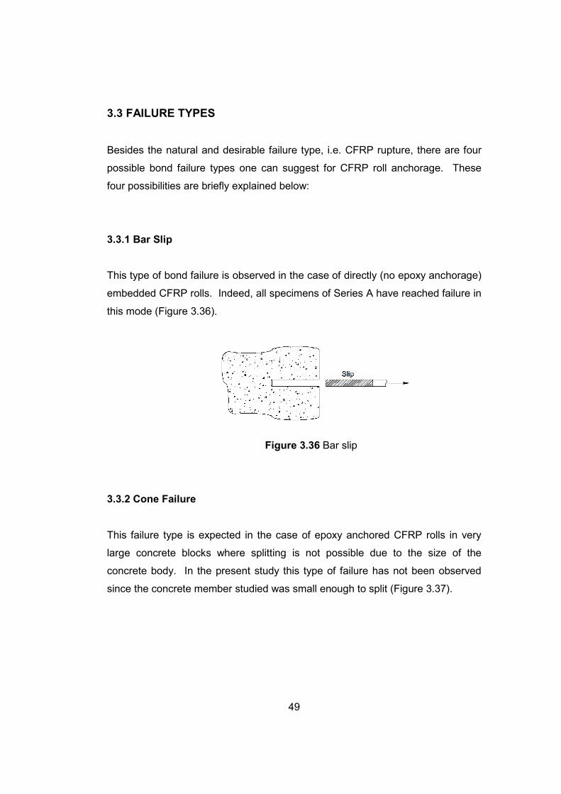
3.3.1 Bar Slip
This type of bond failure is observed in the case of directly (no epoxy anchorage)
embedded CFRP rolls. Indeed, all specimens of Series A have reached failure in
this mode (Figure 3.36).
Figure 3.36 Bar slip
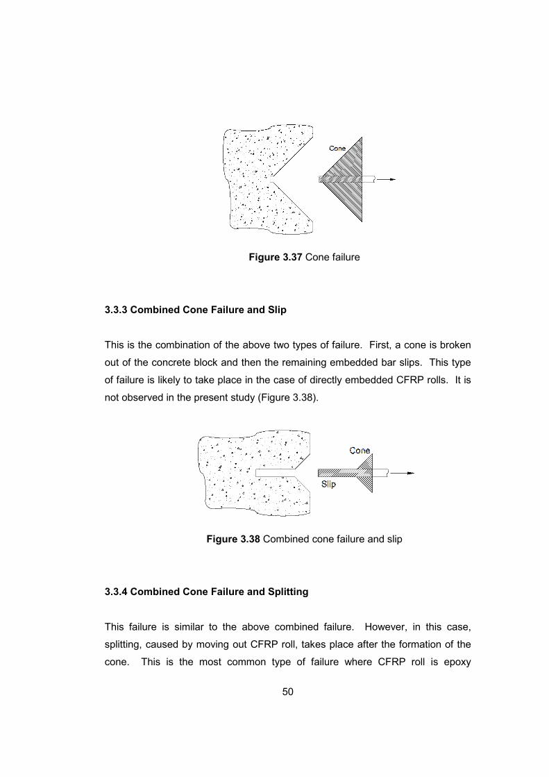
3.3.2 Cone Failure
This failure type is expected in the case of epoxy anchored CFRP rolls in very
large concrete blocks where splitting is not possible due to the size of the
concrete body. In the present study this type of failure has not been observed
since the concrete member studied was small enough to split (Figure 3.37).
50
Figure 3.37 Cone failure
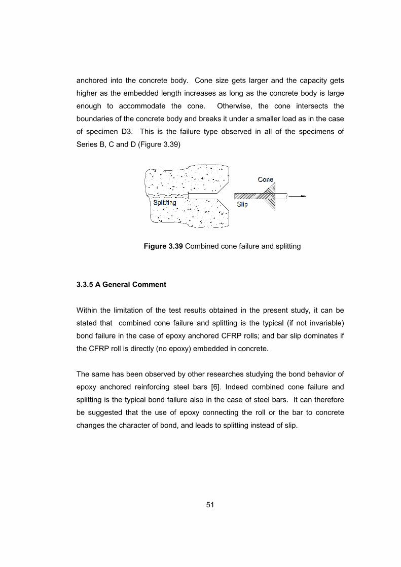
3.3.3 Combined Cone Failure and Slip
This is the combination of the above two types of failure. First, a cone is broken
out of the concrete block and then the remaining embedded bar slips. This type
of failure is likely to take place in the case of directly embedded CFRP rolls. It is
not observed in the present study (Figure 3.38).
Figure 3.38 Combined cone failure and slip
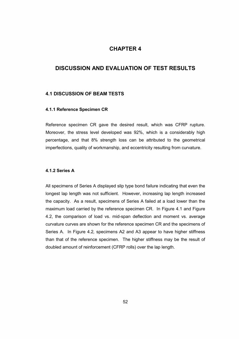
3.3.4 Combined Cone Failure and Splitting
This failure is similar to the above combined failure. However, in this case,
splitting, caused by moving out CFRP roll, takes place after the formation of the
cone. This is the most common type of failure where CFRP roll is epoxy
51
anchored into the concrete body. Cone size gets larger and the capacity gets
higher as the embedded length increases as long as the concrete body is large
enough to accommodate the cone. Otherwise, the cone intersects the
boundaries of the concrete body and breaks it under a smaller load as in the case
of specimen D3. This is the failure type observed in all of the specimens of
Series B, C and D (Figure 3.39)
Figure 3.39 Combined cone failure and splitting
3.3.5 A General Comment
Within the limitation of the test results obtained in the present study, it can be
stated that combined cone failure and splitting is the typical (if not invariable)
bond failure in the case of epoxy anchored CFRP rolls; and bar slip dominates if
the CFRP roll is directly (no epoxy) embedded in concrete.
The same has been observed by other researches studying the bond behavior of
epoxy anchored reinforcing steel bars [6]. Indeed combined cone failure and
splitting is the typical bond failure also in the case of steel bars. It can therefore
be suggested that the use of epoxy connecting the roll or the bar to concrete
changes the character of bond, and leads to splitting instead of slip.
52
CHAPTER 4
DISCUSSION AND EVALUATION OF TEST RESULTS
4.1 DISCUSSION OF BEAM TESTS
4.1.1 Reference Specimen CR
Reference specimen CR gave the desired result, which was CFRP rupture.
Moreover, the stress level developed was 92%, which is a considerably high
percentage, and that 8% strength loss can be attributed to the geometrical
imperfections, quality of workmanship, and eccentricity resulting from curvature.
4.1.2 Series A
All specimens of Series A displayed slip type bond failure indicating that even the
longest lap length was not sufficient. However, increasing lap length increased
the capacity. As a result, specimens of Series A failed at a load lower than the
maximum load carried by the reference specimen CR. In Figure 4.1 and Figure
4.2, the comparison of load vs. mid-span deflection and moment vs. average
curvature curves are shown for the reference specimen CR and the specimens of
Series A. In Figure 4.2, specimens A2 and A3 appear to have higher stiffness
than that of the reference specimen. The higher stiffness may be the result of
doubled amount of reinforcement (CFRP rolls) over the lap length.
53
Figure 4.1 Load vs. mid-span deflection curves of CR and Series A
Figure 4.2 Moment vs. average curvature curves of CR and Series A
54
4.1.3 Series B
All specimens of Series B displayed combined cone and splitting type bond
failure. Increasing epoxy lap length increased the capacity; however, even the
longest lap length was not enough to make use of the full capacity of the rolls.
Unexpectedly in specimen B1, the ultimate load carried was approximately the
same as the load carried by B2. However, this might be due to the difference of
the distances between the rolls in the precast central block to which they were
epoxy anchored. In B1, this distance was so small that at some points the
concrete layer between the holes was missing, which may have caused
interaction between the rolls due to the epoxy, and it is possible that the
specimen artificially behaved stronger than expected. In other words, the rolls
were not completely epoxy anchored to the concrete but also at some points to
each other.
4.1.4 Series C
Increasing the cover thickness did not affect the capacity. If specimens C3 and
B3 are compared, it was observed that like Series B, the only specimen of Series
C (C3) also displayed combined cone and splitting failure. In Figure 4.3 and
Figure 4.4, the comparison of load vs. mid-span deflection and moment vs.
average curvature curves are shown for reference specimen, Series B and Series
C. Although the load vs. mid-span deflection curves have approximately the
same stiffness, the stiffness of the specimen C3 seems less than the others in
Figure 4.4. The reason for this may be either an error in the curvature
measurement tool, or the nature of the specimen itself since the specimens of
Series B and C are not monolithically cast.
55
Figure 4.3 Load vs. mid-span deflection curves of CR, Series B, and Series C
Figure 4.4 Moment vs. average curvature curves of CR, Series B, and Series C

56
4.1.5 Comparison of Series A and Series B
Series A and Series B had the same specimens with only the difference in the
type of the lap splice. Series A had lap splices directly embedded in concrete
and Series B had lap splices epoxy anchored to the precast central blocks.
Specimens of Series A displayed slip failures and specimens of Series B
displayed combined cone and splitting failures, consistently. The difference in
the failure type may be due to the difference between the embedded lap and
anchored lap, in which epoxy anchorage may have been the reason of the
difference as explained earlier in Section 3.3. However, surprisingly, the failure
loads of each corresponding specimens of the same lap length in Series A and B
are approximately the same. However, this may be a coincidence.
Although the full material capacity was not achieved in any one of the tests, in the
study by [2] Gökdemir, H., “Seismic Strengthening of Beam-Column Joints in
Existing R/C Structures by using CFRP rolls”, 2ω epoxy anchored lap length
appeared to be very satisfactory to provide the improvement equivalent to that
obtained by using CFRP rolls anchored at both ends in the beam-column joint.
Neither splitting nor slip failures were observed.
4.2 DISCUSSION OF DIRECT PULL-OUT TESTS
The desirable bond behavior was expected to lead to the rupture of CFRP rolls
without any premature failures. The target failure load was 136 kN in the case of
CFRP rupture considering the strength value provided by the manufacturer.
However, none of the specimens failed by rupture in the rolls. Instead, they failed
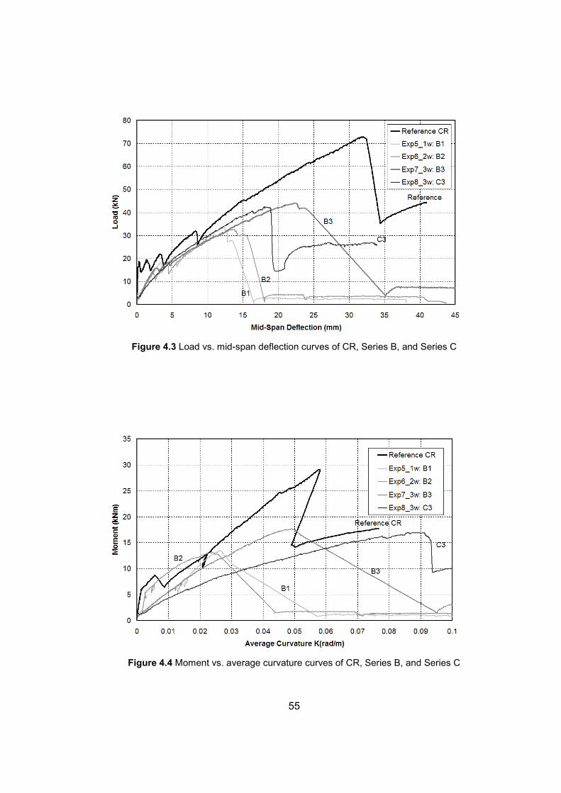
by combined cone and splitting failure. When load vs. average extension curves
are plotted on the same graph, it is observed that increasing epoxy lap length
from 1ω to 2ω increased the capacity, but increasing the length from 2ω to 3ω
did not increase the capacity (Figure 4.5). On the contrary, specimen D3 failed at
a lower load compared to D2.
57
Figure 4.5 Load vs. average extension curves of Series D
For Series D, it can be stated that increasing epoxy anchored lap length does not
necessarily increase the capacity of the specimens since the section dimensions
are kept constant and epoxy anchored lap length was increased. Referring to the
failure types explained in Section 3.3, potential failure cone gets larger when the
lap length is increased. In the case of a small lap length, a proper small cone can
neatly form, but in the case of a much larger lap length, the potential cone can
exceed the boundaries of the specimen and can lead to a truncated cone that
may form under a smaller load.
58
CHAPTER 5
CONCLUSIONS AND RECOMMENDATIONS FOR FUTURE STUDIES
5.1 CONCLUSIONS
Eight beam tests and three direct pull-out tests were performed in this study.
Unfortunately, these tests have not served the purpose satisfactorily. In other
words, a satisfactory “anchored lap length” concept could not be established on
the basis of the experimental results. All specimens failed prematurely in
different modes of failure, depending on the type and size of the specimens.
However, a reasonable insight could be obtained into the anchorage behavior
and lap splice behavior of CFRP rolls in the present pilot study.
The conclusions derived from the observation are briefly listed and explained in
the paragraphs below.
5.1.1 Conclusions from Beam Tests
Beams reinforced for flexure with two continuous CFRP rolls have proved to be
successful test specimens to test tensile capacities of the rolls used in the beam
as tension reinforcement. The rolls have been tested without creating any stress
concentration. Tests made on this kind of specimen gave 92% stress level
developing in the rolls, which is a considerably high percentage of the tensile
capacity of carbon fibers.
Beams reinforced for flexure with lap spliced CFRP rolls that are embedded
directly in concrete have resulted in increasing capacities with increasing lap

59
length. Even the longest lap length of 3ω was not sufficient enough to make use
of the full material capacity of the rolls. However, longer lap lengths can be
tested for different combinations of CFRP strip width (ω) and concrete strength
(fc) to obtain a reasonable “embedded lap length” concept.
Beams reinforced for flexure with epoxy anchored lap splices to the precast
central blocks have indicated that the capacity increases as the lap length
increases. However, all the specimens of this type failed prematurely in
combined cone and splitting mode without being able to develop full material
capacity of carbon fibers since the specimen size was evidently not sufficiently
large. Therefore, it can be stated that this kind of test specimen needs to be
improved to investigate the lap splice behavior of CFRP rolls.
One important observation made was the type of bond failure observed in Series
A (embedded lap splices) and Series B (anchored lap splices). All the embedded
lap splices led to slip type bond failure, whereas all the anchored lap splices to
combined cone and splitting type bond failure. Since the two series were
identical with the exception of CFRP roll anchorage, the difference can directly be
attributed to the epoxy anchorages, i.e. to the stress transfer throughout the
epoxy layer instead of direct bond. The difference was clearly observed, but a
clear and satisfactory explanation could not be developed in this pilot
investigation.
5.1.2 Conclusions from Direct Pull-Out Tests
Although all the specimens in this group have failed prematurely, this type of
testing may be quite suitable for studying lap splice behavior and strength of
CFRP rolls if the dimensions are adjusted considering the potential cone size.
There is no problem of deviation from direct tension. It is possible to get
eccentric tension, but this problem can be minimized by using two pins at each
end of the specimen.
60
As expected, increasing lap lengths led to increasing capacities in the cases
where the specimen was large enough to accommodate the failure cone.
The smaller capacity obtain in the case of the largest lap length was a clear
indication of the importance of specimen size related to the lap length. In other
words, it is clearly understood that the specimen size needs to be determined in
relation to the lap length.
At the end of tests, no epoxy anchored lap length formulation in terms of the used
carbon fiber strip width (ω) could be developed since full material capacity of
carbon fibers is not developed in any of the specimens. However, concerning
bond behavior, a few interesting observations have been made concerning failure
types.
5.2 RECOMMENDATIONS FOR FUTURE STUDIES
The present study was a pilot study. It revealed the importance of some factors
which had not been taken into consideration at the planning stage of the present
work. In the light of the results obtained, new projects can be developed to yield
better and more reliable and more useful results. The following are a few
recommendations for further research.
To improve both the beam tests and the direct pull-out tests,
• Either larger cross-sectional dimensions should be chosen or smaller
CFRP rolls (smaller ω) should be used in similar size specimens.
Moreover, using higher strength concrete may improve the behavior for
premature failures.
• The use of a nominal web reinforcement reflects the actual problems
much better and at the same time will probably improve the splice
behavior. (Remember the rather satisfactory performance of 2ω lap
61
spliced CFRP rolls used in joint strengthening research project [2]
mentioned in Section 4.1.5)
Once a satisfactory test specimen is developed, then a few parameters which
seem to be important can be systematically studied. These parameters are:
• Concrete strength fc
• CFRP strip width ω
• Lap length in terms of ω
• Anchor hole diameter (i.e. thickness of epoxy layer)
• Distance between the two lapped rolls
• Cover (distance to the outermost concrete fiber)
62
REFERENCES [1] Erdoğan, H., “Improvement of Punching Behavior and Strength by CFRP
Rolls”, PhD. thesis in progress, Department of Civil Engineering, Middle East
Technical University, Ankara, Turkey.
[2] Gökdemir, H., “Seismic Strengthening of Beam-Column Joints in Existing R/C
Structures”, PhD. thesis in progress, Department of Civil Engineering, Osmangazi
University, Eskişehir, Turkey.
[3] Özdemir, G., “Mechanical Properties of CFRP Anchorages”, MSc. thesis,
January 2005, Department of Civil Engineering, Middle East Technical University,
Ankara, Turkey.
[4] Akın, E., “Strengthening of Brick Infilled Reinforced Concrete Frames with
CFRP Sheets”, PhD. thesis in progress, Department of Civil Engineering, Middle
East Technical University, Ankara, Turkey.
[5] “MBT-MBRACE FIBER”, Degussa Catalogue, Germany, 2003.
[6] “Personal communication “, Tankut, T., Department of Civil Engineering,
Middle East Technical University, Ankara, Turkey.
63
APPENDIX A
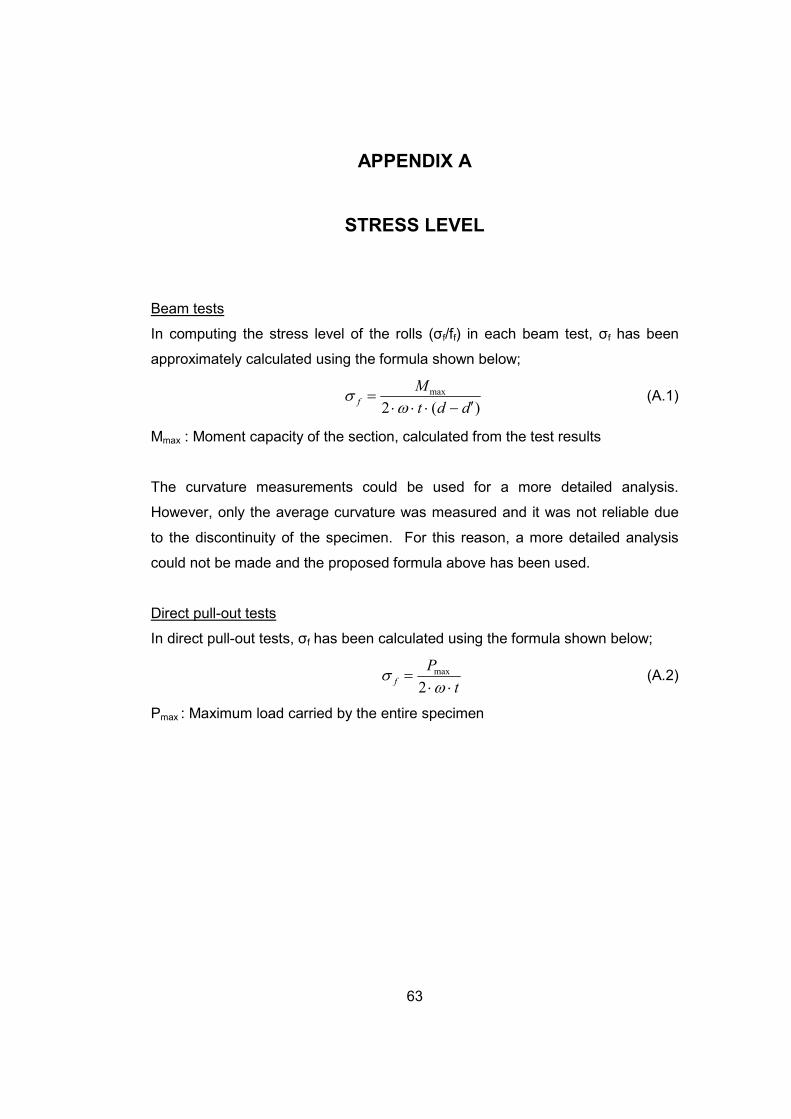
STRESS LEVEL Beam tests
In computing the stress level of the rolls (σf/ff) in each beam test, σf has been
approximately calculated using the formula shown below;
)(2
max
ddt
Mf
′−⋅⋅⋅=
ωσ (A.1)
Mmax : Moment capacity of the section, calculated from the test results
The curvature measurements could be used for a more detailed analysis.
However, only the average curvature was measured and it was not reliable due
to the discontinuity of the specimen. For this reason, a more detailed analysis
could not be made and the proposed formula above has been used.
Direct pull-out tests
In direct pull-out tests, σf has been calculated using the formula shown below;
t
Pf
⋅⋅=
ωσ
2
max (A.2)
Pmax : Maximum load carried by the entire specimen