lanthanum chloride scintillator for x-ray detection - saint-gobain … · keywords: scintillator,...
TRANSCRIPT

Lanthanum Chloride Scintillator for X-ray Detection
T. Martin and C. Allier and F. Bernard
ESRF, Cyberstar and Saint Gobain
Abstract. In this presentation we describe the testing of a new cerium doped Lanthanum Chloride crystal (LaCl3:Ce), which makes an excellent scintillation material for X-ray counting applications. Detailed measurements were taken to determine the properties of the scintillator over an energy range of 5 to 60KeV; the results demonstrate that, when used with an appropriate PMT, the crystal sustains high count rates, minimal dead time and good energy resolution. For example an energy resolution of 35% (FWHM) was achieved at 22KeV and count rates of up to 1MHz are possible without dead-time correction. A comparison of LaCl3:Ce with two conventional scintillation materials, YAP:Ce and NaI(Tl) is also presented, which shows that that LaCl3:Ce offers a good balance of performance parameters for X-ray experiments.
Keywords: Scintillator, LaCl3:Ce, x-ray, detector PACS: 07.85.-m X and gamma ray instruments, 07.85.Qe Synchrotron Radiation Instrumentation
INTRODUCTION
NaI(Tl) and YAP:Ce counting detectors are readily available and used for a variety of experiments on Synchrotron beamlines. NaI(Tl) based systems demonstrate excellent energy resolution but are limited to count rates of up to 500Kcps, whereas YAP:Ce scintillators can count up to 5Mcps (with counting loss correction). Although YAP:Ce scintillators have high count rate, at energies below 20keV they have poor resolution and so separation of the signal from underlying noise can not be achieved.
Lanthanum Chloride is a new commercial material that seems to offer good energy resolution and fast emission. This manuscript provides an overview of some of the testing carried out on the material over a 5keV to 60keV energy, including measurement of energy resolution and dead time.
Experimental Set-up
These tests were performed using a scintillation counter and processing electronics module available from Oxford Danfysik, produced by Cyberstar.
The scintillation detector head consists of a scintillation crystal from Saint Gobain, a Hamamatsu 10-stage photomultiplier tube (PMT) and a preamplifier. The PMT has a rise time of 2.5ns, a transit time spread of 2.2ns and a sufficiently high anode current limit. The system is operated between 800V and 1000V and the quantum efficiency of the PMT is well matched with YAP:Ce and LaCl3:Ce scintillators; 26% at 370nm.
The processing electronics (X2000 – CBY-2202) is widely used on synchrotron beamlines all over the world. It has a fast preamplifier and fast shaping constants (50ns to 1μs peaking time). The faster shaping times are used for YAP:Ce and LaCl3:Ce scintillation crystals and the slower shaping times for NaI(Tl) scintillators.
Energy Resolution Measurement
In order to measure the detector heads energy resolution it was irradiated with an iron source (55Fe – 5.9 KeV) and a cadmium source (109Cd – 22KeV). The PMT signal was then processed with the X2000 unit detailed above; the spectrum, shown in Fig.1, was recorded with peaking time of 100ns.
1156
Downloaded 01 Sep 2007 to 128.84.158.108. Redistribution subject to AIP license or copyright, see http://proceedings.aip.org/proceedings/cpcr.jsp

Energy resolution for the 22keV peak was measured at about 35% (FWHM) at room temperature. The peak to valley ratio is excellent at 5.9keV; approximately 20, compared to the ratio of about 5 for YAP. Table 1 shows results for both YAP an LaCl3 scintillators.
FIGURE 1. Spectrum recorded with LaCl3:Ce scintillator
TABLE 1. LaCl3: Gain 100, 55Fe source (5.9keV)
55Fe source (5.9keV) 109Cd source (22keV) High Voltage (V) ΔE/E (peaking
time=100ns) ΔE/E (peaking time=300ns)
ΔE/E (peaking time=100ns)
ΔE/E (peaking time=300ns)
850 80% 130% 39% 38% 900 75% 84% 37% 35% 950 69% 77% 34% 35% 1000 70% 73% 25% 34%
Count Rate Measurement
When the distance between the radioactive source and the scintillator is reduced the data input is increased, subsequently modifying the pulse height of the preamplifier. Fig. 2 shows the pulse height of the preamplifier output when excited with a 109Cd source, versus count rate. It is shown that the pulse height is stable until ∼900000cps for both YAP and LaCl3 scintillators; the amplitude begins to decrease above count rates of around 1 MHz. This limitation is due to the passive divider network of the PMT, which doesn’t allow constant PMT gain at high count rate – this means that for count rates higher than 1Mcps the lower threshold must be very accurately set.
0.8
0.9
1
1.1
1.2
1.3
1.4
1.5
1.6
104 105 106 107
YAP:Ce PA output
Pul
se h
eigh
t of o
utpu
t PA
Count rate (cps)
1.06
1.08
1.1
1.12
1.14
1.16
1.18
104 105 106 107
LaCl3 PA output
Pul
se h
eigh
t of o
utpu
t PA
Count rate (cps) FIGURE 2. Pulse height of the preamplifier output vs. the count rate for YAP (left) and LaCl3 (right)
-5000
0
5000
1 104
1.5 10 42 104
2.5 10 43 104
3.5 10 4
0 500 1000 1500 2000
LaCl3:Ce
Fe sourceCd source
Count
Channel
1157
Downloaded 01 Sep 2007 to 128.84.158.108. Redistribution subject to AIP license or copyright, see http://proceedings.aip.org/proceedings/cpcr.jsp
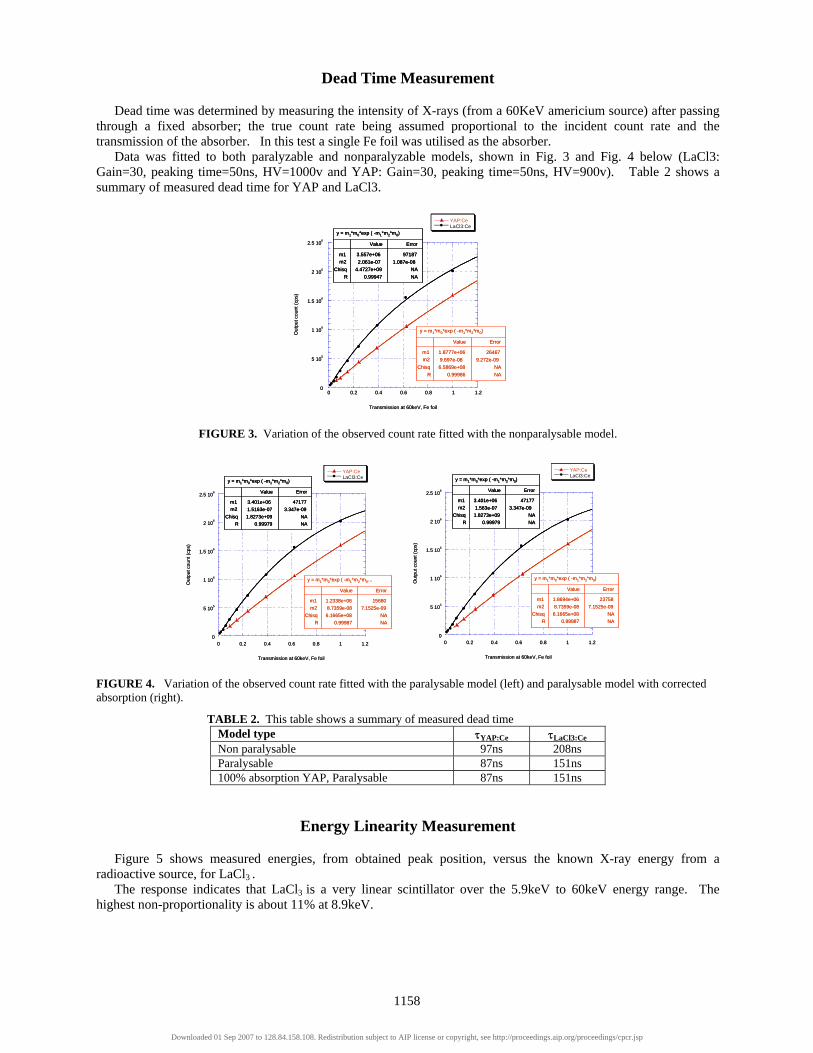
Dead Time Measurement
Dead time was determined by measuring the intensity of X-rays (from a 60KeV americium source) after passing through a fixed absorber; the true count rate being assumed proportional to the incident count rate and the transmission of the absorber. In this test a single Fe foil was utilised as the absorber.
Data was fitted to both paralyzable and nonparalyzable models, shown in Fig. 3 and Fig. 4 below (LaCl3: Gain=30, peaking time=50ns, HV=1000v and YAP: Gain=30, peaking time=50ns, HV=900v). Table 2 shows a summary of measured dead time for YAP and LaCl3.
FIGURE 3. Variation of the observed count rate fitted with the nonparalysable model.
FIGURE 4. Variation of the observed count rate fitted with the paralysable model (left) and paralysable model with corrected absorption (right). TABLE 2. This table shows a summary of measured dead time
Model type τYAP:Ce τLaCl3:Ce Non paralysable 97ns 208ns Paralysable 87ns 151ns 100% absorption YAP, Paralysable 87ns 151ns
Energy Linearity Measurement
Figure 5 shows measured energies, from obtained peak position, versus the known X-ray energy from a radioactive source, for LaCl3 .
The response indicates that LaCl3 is a very linear scintillator over the 5.9keV to 60keV energy range. The highest non-proportionality is about 11% at 8.9keV.
0
5 105
1 106
1.5 106
2 106
2.5 106
Out
put c
ount
(cps
)
0 0.2 0.4 0.6 0.8 1 1.2
Transmission at 60keV, Fe foil
y = m1*m0*exp ( -m1*m2*m0)
ErrorValue
971873.557e+06m1 1.087e-082.061e-07m2
NA4.4727e+09ChisqNA0.99947R
y = m1*m0*exp ( -m1*m2*m0)
ErrorValue
264671.8777e+06m1 9.272e-099.697e-08m2
NA6.5869e+08ChisqNA0.99986R
YAP:CeLaCl3:Ce
0
5 105
1 106
1.5 106
2 106
2.5 106
Out
put c
ount
(cps
)
0 0.2 0.4 0.6 0.8 1 1.2
Transmission at 60keV, Fe foil
y = m1*m0*exp ( -m1*m2*m0)
ErrorValue
971873.557e+06m1 1.087e-082.061e-07m2
NA4.4727e+09ChisqNA0.99947R
y = m1*m0*exp ( -m1*m2*m0)
ErrorValue
971873.557e+06m1 1.087e-082.061e-07m2
NA4.4727e+09ChisqNA0.99947R
y = m1*m0*exp ( -m1*m2*m0)
ErrorValue
971873.557e+06m1 1.087e-082.061e-07m2
NA4.4727e+09ChisqNA0.99947R
y = m1*m0*exp ( -m1*m2*m0)
ErrorValue
971873.557e+06m1 1.087e-082.061e-07m2
NA4.4727e+09ChisqNA0.99947R
y = m1*m0*exp ( -m1*m2*m0)
ErrorValue
264671.8777e+06m1 9.272e-099.697e-08m2
NA6.5869e+08ChisqNA0.99986R
y = m1*m0*exp ( -m1*m2*m0)
ErrorValue
264671.8777e+06m1 9.272e-099.697e-08m2
NA6.5869e+08ChisqNA0.99986R
y = m1*m0*exp ( -m1*m2*m0)
ErrorValue
264671.8777e+06m1 9.272e-099.697e-08m2
NA6.5869e+08ChisqNA0.99986R
YAP:CeLaCl3:CeYAP:CeLaCl3:Ce
0
5 105
1 106
1.5 106
2 106
2.5 106
0 0.2 0.4 0.6 0.8 1 1.2
Out
put c
ount
(cps
)
Transmission at 60keV, Fe foil
y = m1*m0*exp ( -m1*m2*m0…
ErrorValue
156801.2338e+06m1 7.1525e-098.7359e-08m2
NA6.1665e+08ChisqNA0.99987R
y = m1*m0*exp ( -m1*m2*m0)
ErrorValue
471773.401e+06m1 3.347e-091.5163e-07m2
NA1.8273e+09ChisqNA0.99979R
YAP:CeLaCl3:Ce
0
5 105
1 106
1.5 106
2 106
2.5 106
0 0.2 0.4 0.6 0.8 1 1.2
Out
put c
ount
(cps
)
Transmission at 60keV, Fe foil
y = m1*m0*exp ( -m1*m2*m0…
ErrorValue
156801.2338e+06m1 7.1525e-098.7359e-08m2
NA6.1665e+08ChisqNA0.99987R
y = m1*m0*exp ( -m1*m2*m0…
ErrorValue
156801.2338e+06m1 7.1525e-098.7359e-08m2
NA6.1665e+08ChisqNA0.99987R
y = m1*m0*exp ( -m1*m2*m0…
ErrorValue
156801.2338e+06m1 7.1525e-098.7359e-08m2
NA6.1665e+08ChisqNA0.99987R
y = m1*m0*exp ( -m1*m2*m0)
ErrorValue
471773.401e+06m1 3.347e-091.5163e-07m2
NA1.8273e+09ChisqNA0.99979R
y = m1*m0*exp ( -m1*m2*m0)
ErrorValue
471773.401e+06m1 3.347e-091.5163e-07m2
NA1.8273e+09ChisqNA0.99979R
y = m1*m0*exp ( -m1*m2*m0)
ErrorValue
471773.401e+06m1 3.347e-091.5163e-07m2
NA1.8273e+09ChisqNA0.99979R
y = m1*m0*exp ( -m1*m2*m0)
ErrorValue
471773.401e+06m1 3.347e-091.5163e-07m2
NA1.8273e+09ChisqNA0.99979R
YAP:CeLaCl3:CeYAP:CeLaCl3:Ce
0
5 105
1 106
1.5 106
2 106
2.5 106
0 0.2 0.4 0.6 0.8 1 1.2
Out
put c
ount
(cps
)
Transmission at 60keV, Fe foil
YAP:CeLaCl3:Ce
y = m1*m0*exp ( -m1*m2*m0)
ErrorValue
237581.8694e+06m1 7.1525e-098.7359e-08m2
NA6.1665e+08ChisqNA0.99987R
y = m1*m0*exp ( -m1*m2*m0)
ErrorValue
471773.401e+06m1 3.347e-091.563e-07m2
NA1.8273e+09ChisqNA0.99979R
0
5 105
1 106
1.5 106
2 106
2.5 106
0 0.2 0.4 0.6 0.8 1 1.2
Out
put c
ount
(cps
)
Transmission at 60keV, Fe foil
YAP:CeLaCl3:Ce
y = m1*m0*exp ( -m1*m2*m0)
ErrorValue
237581.8694e+06m1 7.1525e-098.7359e-08m2
NA6.1665e+08ChisqNA0.99987R
y = m1*m0*exp ( -m1*m2*m0)
ErrorValue
237581.8694e+06m1 7.1525e-098.7359e-08m2
NA6.1665e+08ChisqNA0.99987R
y = m1*m0*exp ( -m1*m2*m0)
ErrorValue
237581.8694e+06m1 7.1525e-098.7359e-08m2
NA6.1665e+08ChisqNA0.99987R
y = m1*m0*exp ( -m1*m2*m0)
ErrorValue
471773.401e+06m1 3.347e-091.563e-07m2
NA1.8273e+09ChisqNA0.99979R
y = m1*m0*exp ( -m1*m2*m0)
ErrorValue
471773.401e+06m1 3.347e-091.563e-07m2
NA1.8273e+09ChisqNA0.99979R
y = m1*m0*exp ( -m1*m2*m0)
ErrorValue
471773.401e+06m1 3.347e-091.563e-07m2
NA1.8273e+09ChisqNA0.99979R
y = m1*m0*exp ( -m1*m2*m0)
ErrorValue
471773.401e+06m1 3.347e-091.563e-07m2
NA1.8273e+09ChisqNA0.99979R
1158
Downloaded 01 Sep 2007 to 128.84.158.108. Redistribution subject to AIP license or copyright, see http://proceedings.aip.org/proceedings/cpcr.jsp

0
500
1000
1500
2000
2500
0 10 20 30 40 50 60 70
LaCl3
y = -58.08 + 41.687x R= 0.99964
Cha
nnel
on
MC
A
Energy (keV) FIGURE 5. Graph demonstrating the energy linearity of LaCl3 (HV = 960v, Gain = 40, peaking time =100ns)
CONCLUSIONS
LaCl3:Ce crystal is a promising crystal for X-ray counting applications; demonstrating a compromise between energy resolution and high counting rate. The scintillator can be used up to 1MHz without dead time correction and the theoretical maximum count rate, using the paralysable model, is 2.5 Mcps. These results were obtained using a radioactive source; future experimentation, to confirm the crystals potential, should be carried out on a Synchrotron beamline.
High quality LaCl3 scintillation detectors, with integrated state-of-the-art pre-amplifiers and ancillary electronics are now available from Oxford Danfysik (shown in Fig. 6 below).
FIGURE 6. Scintillation detector heads and count processing modules available from Oxford Danfysik.
REFERENCES
1. K.S. Shah, J. Glodo, M. Klugerman, L. Cirignano, W.W. Moses, S.E. Derenzo and M.J. Weber, LaCl3:Ce scintillator for Gamma ray detection, Accepted by NIM, to be published.
2. O. Guillot-Noël, J.T.M. de Haas, P. Dorenbos, C.W.E. van Eijk, K. Kramer and H.U. Güdel, Optical and scintillation properties of cerium-doped LaCl3, LuBr3, and LuCl3., Journal of luminescence 85(1999) 21-35 published.
3. M. Harada, K. Sakurai, H. Eba and S. Kishimoto, Performance of the YAP:Ce Scintillation detector, Photon factory activity report 1998, pp292
4. M. Balcerzyk, M. Moszynski, M. Kapusta, Comparison of LaCl3:Ce and NaI(Tl) scintillators in γ-ray spectrometry, NIM A 537 (2005) 50-56
5. Bicron documentation, http:www.detectors.saint -gobain.com
1159
Downloaded 01 Sep 2007 to 128.84.158.108. Redistribution subject to AIP license or copyright, see http://proceedings.aip.org/proceedings/cpcr.jsp

Energy resolution Energy resolution was determined using both a 55Fe source (5.9 keV) and a 109Cd source (22 keV). Energy resolution for the 22 keV peak was measured to be about 35% (FWHM) at room temperature. The peak to valley ratio is excellent at 5.9 keV; approximately 20, compared to the ratio of about 5 for YAP. The spectrums summarised in table 1 below were recorded with a LaCl3 scintillator, (gain 100.)
Dead Time MeasurementDead time was determined by measuring the intensity of X-rays, from an Am source, after passing through a fixed absorber; the true count rate being assumed proportional to the incident count rate and the transmission of the absorber. In this test a single Fe foil was utilised as the absorber. Data was fitted to both paralyzable and nonparalyzable models, shown below (LaCl3: Gain=30, peaking time=50 ns, HV=1000 v and YAP: Gain=30, peaking time=50 ns, HV=900 v). Table 2 shows a summary of measured dead time for YAP and LaCl3.
Count Rate Measurement This was measured by reducing the distance between a 109Cd radioactive source and the scintillator, this increases data input and subsequently modifes the pulse height of the preamplifier. Figure 2 shows the pulse height of the preamplifier output versus count rate. It is shown that the pulse height is stable to around 900,000 cps for both YAP and LaCl3 scintillators; the amplitude begins to decrease above count rates of around 1 MHz. This limitation is due to the passive divider network of the PMT, which doesn’t allow constant PMT gain at high count rate – this means that for count rates higher than 1Mcps the lower threshold must be very accurately set.
Energy Linearity MeasurementFigure 5 shows measured energies, from obtained peak position, versus the known X-ray energy from a radioactive source. The response indicates that LaCl3 is a very linear scintillator over the 5.9 keV to 60 keV energy range. The highest non-proportionality is about 11% at 8.9 keV.
Conclusion
LaCl3:Ce crystal is a promising crystal for X-ray counting applications; demonstrating a compromise between energy resolution and high counting rate. The scintillator can be used up to 1 MHz without dead time correction and the theoretical maximum count rate, using the paralysable model, is 2.5 Mcps.
These results were obtained using a radioactive source; future experimentation, to confirm the crystals potential, should be carried out on a Synchrotron beamline.
LaCl3 production and detector manufactureThese tests were performed using a scintillation counter and processing electronics module available from Oxford Danfysik. Oxford Danfysik provides a full range of scintillation detector heads with various dimensions, crystal types, and thicknesses; allowing you to match a product to your efficiency, resolution, speed, and integration requirements.
The processing modules are designed to obtain maximum performance from the entire scintillation detection range. The scintillation detector head consists of a scintillation crystal, a Hamamatsu 10-stage photomultiplier tube (PMT) and a preamplifier. The processing electronics (X2000 – CBY-2202) is widely used on synchrotron beamlines all over the world.
In this presentation we describe the testing of a new Cerium doped Lanthanum Chloride crystal (LaCl3:Ce), which makes an excellent scintillation material for X-ray counting applications. Detailed measurements were taken to determine the properties of the scintillator over an energy range of 5 to 60 KeV; the results demonstrate that, when used with an appropriate PMT, the crystal sustains high count
rates, minimal dead time and good energy resolution. For example an energy resolution of 35% (FWHM) was achieved at 22 KeV and count rates of up to 1 MHz are possible without dead-time correction.A comparison of LaCl3:Ce with two conventional scintillation materials, YAP:Ce and NaI(Tl) is also presented, which shows that that LaCl3:Ce offers a good balance of performance parameters for X-ray experiments.
References: K.S. Shah, J. Glodo, M.Klugerman, L.Cirignano, W.W. Moses, S.E. Derenzo and M.J. Weber, LaCl3:Ce scintillator for Gamma ray detection.
LaCl3 Scintillator for X-ray detectionT. Martin1, C. Allier2, F. Bernard3 and L. Attwood4
1) ESRF, 2) Cyberstar, 3) Saint Gobain, 4) Oxford Danfysik
0
5 105
1 106
1.5 106
2 106
2.5 106
0 0.2 0.4 0.6 0.8 1 1.2
YAP:CeLaCl3:Ce
Transmission at 60keV, Fe foil
y = m1*M0/(1+m1*m2*M0)ErrorValue
264671.8777e+06m19.272e-099.6978e-08m2
NA6.5869e+08ChisqNA0.99986R
y = m1*M0/(1+m1*m2*M0)ErrorValue
971873.5571e+06m11.0874e-082.0812e-07m2
NA4.4727e+09ChisqNA0.99947R
0
5 105
1 106
1.5 106
2 106
2.5 1066
0 0.2 0.4 0.6 0.8 1 1.2
YAP:CeLaCl3:Ce
Transmission at 60keV, Fe foil
y = m1*M0*exp(-m1*m2*M0)ErrorValue
237581.8694e+06m17.1525e-098.7359e-08m2
NA6.1665e+08ChisqNA0.99987R
y = m1*M0*exp(-m1*m2*M0)ErrorValue
471773.401e+06m13.3472e-091.5163e-07m2
NA1.8273e+09ChisqNA0.99979R
0
5 106
1 106
1.5 106
2 106
2.5 106
0 0.2 0.4 0.6 0.8 1 1.2
YAP:CeLaCl3:Ce
Transmission at 60keV, Fe foil
y = (m1*M0/0.66)*exp(-m1*m2*...ErrorValue
156801.2338e+06m17.1525e-098.7359e-08m2
NA6.1665e+08ChisqNA0.99987R
y = (m1*M0/1)*exp(-m1*m2*M0/...ErrorValue
471773.401e+06m13.3472e-091.5163e-07m2
NA1.8273e+09ChisqNA0.99979R
- 5 0 0 0
0
5 0 0 0
1 1 04
1 . 5 1 04
2 1 04
2 . 5 1 04
3 1 04
3 . 5 1 04
0 5 0 0 1 0 0 0 1 5 0 0 2 0 0 0
LaCl3:Ce
F e s o u r c e
C d s o u r c e
C o u n t
C h a n n e l
0.8
0.9
1
1.1
1.2
1.3
1.4
1.5
1.6
104 105 106 107
YAP:Ce PA output
Pulse height of output PA
Count rate (cps)
Pul
se h
eigh
t of
out
put
P
1.06
1.08
1.1
1.12
1.14
1.16
1.18
104 105 106 107
LaCl3 PA output
Pulse height of output PA
Count rate (cps)
Pul
se h
eigh
t of
out
put
P
FIGURE 2. Pulse height of the preamplifier output vs. the count rate for YAP (left) and LaCl3 (right)
0
500
1000
1500
2000
2500
0 10 20 30 40 50 60 70
LaCl3
y = -58.08 + 41.687x R= 0.99964
Channel on MCA
Energy (keV)
FIGURE 5. Graph demonstrating the linearity of LaCl3 (HV=960 v, Gain=40, peaking time=100 ns)
FIGURE 3. Variation of the observed count rate fitted with the nonparalyzable
FIGURE 4. Variation of the observed count rate fitted with the paralyzable model (left) and paralyzable model with corrected absorption (right).
Model Type τYAP:Ce τLaCl3:Ce
Non paralyzable 97 ns 208 nsParalyzable 87 ns 151 nsParalyzable with absorption correction 87 ns 151 ns
TABLE 2. This table shows a summary of measured dead time
High Voltage (V)
55Fe source (5.9 keV) 109Cd source (22 keV)∆E/E (peaking time=100 ns)
∆E/E (peaking time=300 ns)
∆E/E (peaking time=100 ns)
∆E/E (peaking time=300 ns)
850 80% 130% 39% 38%
900 75% 84% 37% 35%
950 69% 77% 34% 35%
1000 70% 73% 25% 34%
FIGURE 1. Spectrum recorded with LaCl3 scintillator
TABLE 1. Energy resolution for LaCl3
Scintillation detector heads available from Oxford Danfysik
Single and five channel pulse processing modules available from Oxford Danfysik
High quality LaCl3 scintillation detectors, with integrated state-of-the-art pre-amplifiers and ancillary electronics are available from Oxford Danfysik. Please visit www.oxford-danfysik.com for more information.
Schematic of a scintillation based detector system
e-t
Pulse height
Be or Al
window
Scintillator crystal
Incident
x-ray photon
Visible light
generated
inside crystal
Photoelectrons generated
by visible light photons
Photoelectrons
amplified by cascading
down photomultiplier
tube
Output from
detector head
is pulses of
variable peak
height
Output from NIM/19”
module, positive TTL
t
Pulse shaping
Single channel
analyser
High voltage
for PM tube
Narrow scintillation detector incorporated into a powder diffraction end-station (NE-CAT; APS). It has been mounted in a polyethylene
block, which in turn is mounted on a linear translator
All trademarks are the property of their respective owners.