landfill gas monitoring and well functionality - astswmo · landfill gas monitoring and well...
TRANSCRIPT

Landfill Gas Monitoring andWell Functionality
presented by:William R. (Bill) OrrCalifornia Integrated Waste Management BoardJune 18, 2009
2
TopicsStudy to Determine Functionality of Gas Migration Monitoring Probes Is monitoring data collected representative
of actual soil gas conditions in vicinity of the probe
Recommended Best Management Practices based on FindingsCase Study - Investigation of Historical Landfill

We monitor & control to make sure LFG doesn’t migrate and endanger the public & environment
3
Limits Not to exceed 1.25 percent methane in onsite structures. Not to exceed 5 percent methane at the compliance boundary. Trace gases shall be controlled to prevent acute and chronic exposure to
toxic and/or carcinogenic compounds. (14CCR 20921)

Study Approach20 Landfills selected for inclusion in study 10 in northern California
Clovis, Ukiah, Crazy Horse, Kiefer, Corral Hollow, Hillside, Buena Vista, Anderson, Redding/Benton, Red Bluff
10 in southern California Azusa, Bradley, City of HB, Olinda Alpha, Coyote Canyon,
Upland, Milliken, South Chollas, South Miramar, Otay Landfill
10 probes per site A probe is a single monitoring point that may be located
within a well containing multiple depth probes.
190 Probes in study 10 probes removed from study because their construction
was outside of limits of the equipment (e.g. >100 feet deep)4

Functionality Assessment Overview
Pre-Assessment ActivitiesInitial Condition AssessmentGas MonitoringVacuum TestingVideo Borescope InspectionLithology Evaluation
5
Pre-Assessment ActivitiesPre-Notification and On-Site Arrival Landfill operator notified prior to
assessmentSelection of Gas Probes Determined on-site Based on age, depth, and accessibility
Ambient Condition Assessment Ambient atmospheric conditions recordedWeather, barometric pressure, temperature,
wind speed/direction6

Initial Condition AssessmentLocation Assessment Available site maps were cross-checked
against field location of probeProbe Identification Assessment Individual probes should be easily
identifiableProbehead Assembly Assessment Gas monitoring port on every probe
Surface Emissions Monitoring Assessment of wellhead completion and
seal7

Gas Monitoring AssessmentInitial Pressure Readings Probes with significant variation from ambient (e.g. <> 0
pressure) assumed to be functional
LFG Monitoring CH4, CO2, O2, CO, and H2S
Ambient Oxygen Analysis Probes with ambient (e.g. >20%) O2 may be subject to
ambient air intrusion
Depth Trend Analysis Generally, O2 should decrease with depth and CO2 should
increase
Methane Concentration Used to verify functionality more than non-functionality
8

Vacuum TestingKnown vacuum applied to each probeVacuum change over time (e.g. recovery) recorded 120 second recovery period Readings every 30 seconds
9
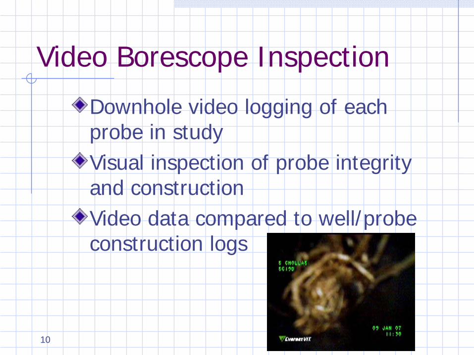
Video Borescope Inspection
Downhole video logging of each probe in studyVisual inspection of probe integrity and constructionVideo data compared to well/probe construction logs
10

Lithology Evaluation
Video verified screened intervals compared to lithology logs
• 14CCR §20925(c)(1)(D) indicates that probe screened intervals should be placed, “preferentially adjacent to soils which are most conducive to gas flow”
11
12
Findings – Initial ConditionsLocation 1 out of 190 probes incorrectly marked
on map
Identification 15 out of 190 probes difficult to identify
Probehead Assembly 10 out of 190 were missing caps
Surface Emissions Monitoring 16 out of 190 had some surface
emissions13
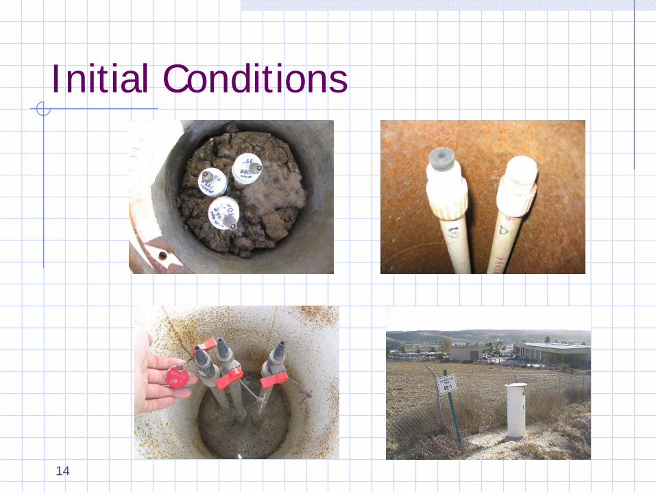
Initial Conditions
14

Findings – Gas MonitoringInitial Pressure 113 out of 190 probes had 0 pressure
LFG Monitoring No H2S or CO detected Some ambient O2 levels
Ambient Oxygen Analysis 37 out of 190 probes had ambient (>20%) O2 levels
Depth Trend Analysis 21 out of 75 wells had increasing O2 with depth
Methane Concentration 23 out of 190 probes had CH4 >5%*
*Note: Not all probes included in study were perimeter compliance probes15

Findings – Vacuum TestingVacuum recovery better for determining functionality, as opposed to determining non-functionality Significant number of probes had quick
vacuum recovery Not necessarily indicative of a non-functional
probe Probes screened in highly permeable zone
would recover quickly
No vacuum recovery indicative of clogged/flooded probe.
16

Findings – Video Borescope
Probe Construction Observations Screened interval verification Pipe connection observation Threaded vs. screwed couplings
Probe Obstruction Observations Soil, roots, insects, paper Construction materials Bentonite, nails, PVC shavings
17

18

Probe Construction Observations
19
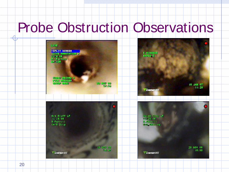
Probe Obstruction Observations
20
Findings – Lithology Evaluation
Probes generally screened in coarse-grained lithologiesAt sites where probes were screened in finer-grained lithologies, no more coarse-grained lithologies were present.
21
Functionality Determination• “Functional” for this study was based on a
combination of observations including condition and location of screens, general condition of well and probe, presence of ambient air in the probe, flooding, and other factors Some probes identified as non-functional
may easily be deemed “functional” with minimal effort Change probehead assembly Additional construction verification Review of historic readings22

Functionality Determination
32% (61 out of 190) probes determined to be non-functional Non-functional as determined by this study
12 probes identified as “indeterminate” Additional data needed to determine
functionality
117 probes identified as functional
23

Conclusions
Probe Identification Proper labels are necessary for valid probe
monitoring Although 25 out of 190 were not properly
labeled, only 4 of these were mis-labeled
Surface Emissions Generally surface emissions around the
wells were not found to be of issue
24
Conclusions (cont.)Probe Construction Use of screws for pipe coupling is
questionable Probe wellheads were generally designed
to function, with a few exceptions Depth to water and screened interval
should be taken into account when designing/constructing probes
Durability of Materials With limited exceptions, probe construction
materials identified in this study were adequate25

26
Best Management Practices

Best Management Practices for LFG Monitoring Wells/Probes1. Probes should be constructed with
longer screened segments2. Probes should be assembled using
materials and in a manner that provides an adequate seal and does not interfere with sampling trace constitutents
3. Minimize the number of probe pipe connections by using longer pipe sections 27
Best Management Practices for LFG Monitoring Wells/Probes
Probes should be constructed using a non-specialized valve on the probe head assemblyLFG wells and probes should be properly labeled and identifiedLFG wells and probes should be constructed to allow access by a bore monitorThe depth of the probe(s) in relation to the water table should be a design consideration 28

Best Management Practices for LFG Monitoring Wells/Probes1. Probes should be preferentially located
as far away from surface vegetation a possible in order to avoid root intrusion
2. A certified engineering geologist/ registered civil engineer must “field design” the screened interval for the probes
3. Perform periodic testing of probes in order to verify functionality
29

CSI: OCHistorical Landfill

CSI: OCLocation: Orange County, CASize: 6.9 acresAge: Operated by County 1958-60Status: Pre-1988 ClosurePostclosure Landuse Former: mobile home park, go-cart track Current: apartments Proposed: home improvement center, self-
storage units 31

CSI: OC
Chronology - 1938
32
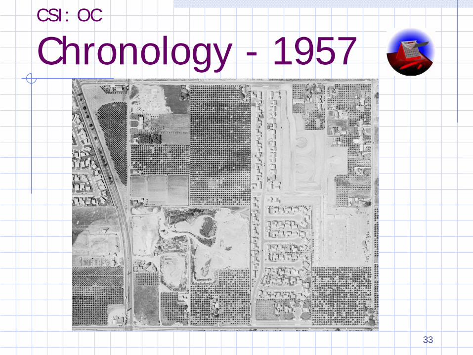
CSI: OC
Chronology - 1957
33

CSI: OC
Chronology - 1960
34
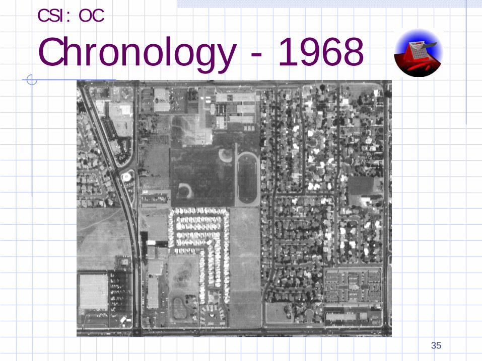
CSI: OC
Chronology - 1968
35
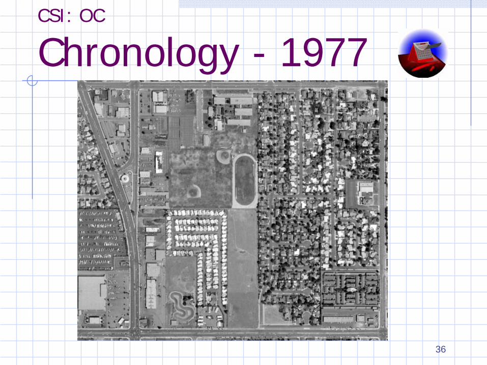
CSI: OC
Chronology - 1977
36

CSI: OC
Chronology - 1979
37

CSI: OC
Chronology - 1990
38

CSI: OC
Chronology - Now
39

40
LFG Monitoring/Network Functionality
P-10R
Ongoing landfill gas migration
issues/parking lot area (P10R)
41
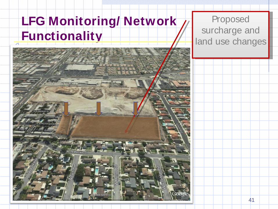
LFG Monitoring/Network Functionality
Proposed surcharge and
land use changes
Investigation Objectives
Assess the operating conditions of LFG monitoring probes and gas extraction wellsDelineate the footprint of wasteAssess potential for LFG migration impacting on-site structures
42
Investigation Methods
Aerial Photography Physical InspectionGeophysical SurveyVideo Borescope InspectionBorings
43

Video Borescope Inspection
44
Preliminary Findings and Conclusions
Encountered Shallow Ground Water (9-15 ft bgs)LFG Probes appear Functional for monitoring perimeter migrationSome LFG Probes are in “screened” waste

Preliminary Findings and Conclusions
9 of 15 LFG extraction wells are impacted by waterExtraction wells may be re-used if headers are redoneA perimeter barrier system may be more effective for LFG control than the extraction wells

47
Special Thanks to:•SCS Engineers •John Bell (retired)
•Abel Martinez-Centeno

For More Information
• LFG Well/Probe Functionality Report http://www.ciwmb.ca.gov/Publications/Organics/2008022.pdf
• Best Management Practices http://www.ciwmb.ca.gov/leaCentral/LandfillGas/Monitoring/BMPWellConst.htm
48

Questions
49