lambda 800/900 user’s guide - uci department of …dmitryf/manuals/perkin elmer lambda 900...
TRANSCRIPT

Lambda 800/900 User’s Guide

Release History Part Number Release Publication Date
09934427 A September 2000 B October 2001
Any comments about the documentation for this product should be addressed to: User Assistance User Assistance PerkinElmer Ltd PerkinElmer Instruments LLC Chalfont Road 710 Bridgeport Avenue Seer Green Shelton Beaconsfield Connecticut 06484-4794 Bucks HP9 2FX U.S.A. United Kingdom Or emailed to: [email protected] Notices The information contained in this document is subject to change without notice. Except as specifically set forth in its terms and conditions of sale, PerkinElmer makes no warranty of any kind with regard to this document, including, but not limited to, the implied warranties of merchantability and fitness for a particular purpose. PerkinElmer shall not be liable for errors contained herein for incidental consequential damages in connection with furnishing, performance or use of this material. Copyright Information This document contains proprietary information that is protected by copyright. All rights are reserved. No part of this publication may be reproduced in any form whatsoever or translated into any language without the prior, written permission of PerkinElmer Instruments LLC. Copyright © 2001 PerkinElmer Instruments LLC. Trademarks Registered names, trademarks, etc. used in this document, even when not specifically marked as such, are protected by law. PerkinElmer is a registered trademark of PerkinElmer, Inc. UV WinLab is a trademark of PerkinElmer, Inc.

Lambda 800/900 User’s Guide
3
Contents Contents .......................................................................................................... 3 Warnings and Safety Information .............................................................. 5 Safety Information.......................................................................................... 7
Safety Information in this Manual........................................................... 7 IEC 61010 Compliance ........................................................................... 8 CSA Compliance ..................................................................................... 8 UL Compliance ....................................................................................... 8 Electrical Protection ................................................................................ 8 Electrical Safety....................................................................................... 8 Electromagnetic Compatibility (EMC) ................................................. 11
Environment ................................................................................................. 12 Operating Conditions............................................................................. 12 Storage Conditions ................................................................................ 12 Other Environmental Conditions........................................................... 13
Warning Labels............................................................................................. 15 Introduction ................................................................................................ 17 About this Manual ........................................................................................ 19
Conventions used in this Manual........................................................... 19 System Description....................................................................................... 20
Optical System....................................................................................... 20 Instrument Purging ................................................................................ 24
Technical Data .............................................................................................. 25 General .................................................................................................. 25 Optics..................................................................................................... 26 Abscissa................................................................................................. 26 Ordinate ................................................................................................. 27 Data Output ........................................................................................... 28 Methods ................................................................................................. 28
Installation................................................................................................... 29 Overview ...................................................................................................... 31
Laboratory Requirements ...................................................................... 32 Unpacking and Inspection ............................................................................ 34
Equipment Provided .............................................................................. 35 System Configuration............................................................................ 36 Connecting to the Line Power Supply................................................... 37 Personal Computer ................................................................................ 38

Lambda 800/900 User’s Guide
4
Printer .................................................................................................... 38 The Single Cell Holder ................................................................................. 39
Description ............................................................................................ 39 Installing the Cell Holder ...................................................................... 39 Aligning the Single-cell Holder............................................................. 41 Fine Alignment...................................................................................... 43 Minimum Volume Applications............................................................ 44
Accessory Installation................................................................................... 45 Removing Parts of the Basic Spectrometer ........................................... 46 Purge Gas Connectors ........................................................................... 56 Accessory Connector Panel ................................................................... 57 Specific Accessory Installation Overviews ........................................... 59 Pin Configuration .................................................................................. 60
Maintenance ................................................................................................ 63 General Maintenance .................................................................................... 65
Daily Care.............................................................................................. 65 Cleaning the Sample Compartment....................................................... 66 Sample Compartment Windows............................................................ 68 Use and Care of Cells ............................................................................ 68
Replacing a Lamp......................................................................................... 70 Halogen Lamp Replacement ................................................................. 70 Deuterium Lamp Replacement.............................................................. 74
Changing Fuses............................................................................................. 78 Replacement Parts ........................................................................................ 80 Appendix - Translations of Warnings....................................................... 81 Translations of Warnings.............................................................................. 83 Index ............................................................................................................ 91 Index ............................................................................................................. 93

Warnings and Safety Information 1


Warnings and Safety Information
7
Safety Information
Safety Information in this Manual
This manual contains information and warnings that must be followed by the user to ensure safe operation and to maintain the instrument in a safe condition.
Possible hazards that could harm the user or result in damage to the instrument are clearly stated at appropriate places throughout this manual, and the following safety conventions are used throughout:
WARNING
We use the term WARNING to inform you about situations that could result in personal injury to yourself or other persons.
Details about these circumstances are in a box like this one.
CAUTION
We use the term CAUTION to inform you about situations that could result in serious damage to the instrument or other equipment
Details about these circumstances are in a box like this one.
Translations of the warning messages used in this handbook are given in Translations of Warnings on page 83.
Before using the instrument it is essential to read the manual carefully and to pay particular attention to any advice concerning potential hazards that may arise from the use of the instrument. The advice is intended to supplement the normal safety code of behavior prevailing in the user’s country.

Lambda 800/900 User’s Guide
8
IEC 61010 Compliance
This instrument has been designed and tested in accordance with IEC 61010-1: Safety requirements for electrical equipment for measurement, control, and laboratory use, and Amendment 1 to this standard.
CSA Compliance
This instrument meets the Canadian Standards Association (CSA) Standard CAN/CSA-C22.2 No. 1010.1-92: Laboratory Equipment.
UL Compliance
This instrument meets the Underwriter Laboratories (UL) Standard UL 3101-1/Oct.93: Electrical Equipment for laboratory use, part 1: general requirements.
Electrical Protection
Insulation: Class I as defined in IEC 61010-1.
Installation Category: The instruments are able to withstand transient overvoltage according to Installation Category II as defined in IEC 61010-1 and IEC 664.
Pollution Degree: The equipment will operate safely in environments that contain non-conductive foreign matter and condensation up to Pollution Degree 2 as defined in IEC 61010-1 and IEC 664.
Electrical Safety
To ensure satisfactory and safe operation of the instrument, it is essential that the green/yellow lead of the line power cord is connected to true electrical earth (ground).
If any part of the instrument is not installed by a PerkinElmer service representative, make sure that the line power plug is wired correctly:

Warnings and Safety Information
9
Cord Lead Colors Terminal
International USA
Live Brown Black
Neutral Blue White
Protective Conductor (earth/ground)
Green/Yellow Green
WARNING
Electrical Hazard Any interruption of the protective conductor inside or outside the instrument or disconnection of the protective conductor (earth/ground) terminal is likely to make the instrument dangerous. Intentional interruption is prohibited. Lethal voltages are present in the instrument • Even with the power switch OFF, line power voltages can still be
present within the instrument. • When the instrument is connected to line power, terminals may be
live, and opening covers or removing parts (except those to which access can be gained without the use of a tool) is likely to expose live parts.
• Capacitors inside the instrument may still be charged even if the instrument has been disconnected from all voltage sources.
When working with the instrument:
• Connect the instrument to a correctly installed line power outlet that has a protective conductor (earth/ground).
• Do not attempt to make internal adjustments or replacements except as directed in this handbook.
• Do not operate the instrument with any covers or parts removed.

Lambda 800/900 User’s Guide
10
• Servicing should be carried out only by a PerkinElmer service representative or similarly authorized and trained person.
• Disconnect the instrument from all voltage sources before opening it for any adjustment, replacement, maintenance, or repair. If, afterwards, the opened instrument must be operated for further adjustment, maintenance, or repair, this must only be done by a skilled person who is aware of the hazard involved.
• Use only fuses with the required current rating and of the specified type for replacement. Do not use makeshift fuses or short-circuit the fuse holders.
• Whenever it is likely that the instrument is no longer electrically safe for use, make the instrument inoperative and secure it against any unauthorized or unintentional operation.
The instrument is likely to be electrically unsafe when it:
• Shows visible damage;
• Fails to perform the intended measurement;
• Has been subjected to prolonged storage under unfavorable conditions;
• Has been subjected to severe transport stresses.
WARNING
If the equipment is used in a manner not specified herein the protection provided by the equipment may be impaired.

Warnings and Safety Information
11
Electromagnetic Compatibility (EMC)
EC Directive
This product complies with the minimum immunity requirements of IEC 61326 and has been tested to the relevant parts of the following standards:
IEC 61000-4-2
IEC 61000-4-3
IEC 61000-4-4
IEC 61000-4-5
IEC 61000-4-6
IEC 61000-4-11
This product complies with EN 55011 and amendment1 Group 1 Class B and with IEC 61000-3-2 and 61000-3-3.
FCC rules and regulations
This product is classified as a digital device used exclusively as industrial, commercial, or medical test equipment. It is exempt from the technical standards specified in Part 15 of the FCC Rules and Regulations, based on Section 15.103(c).

Lambda 800/900 User’s Guide
12
Environment
Operating Conditions
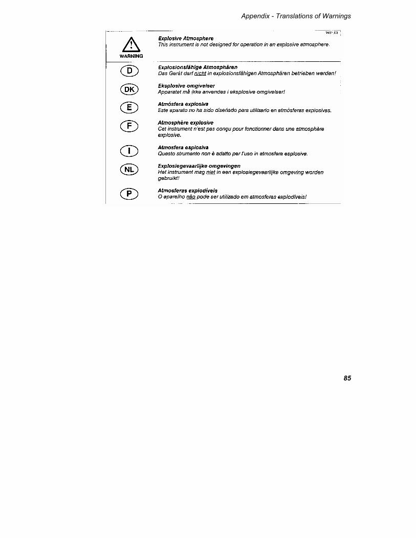
WARNING
Explosive Atmosphere
This instrument is not designed for operation in an explosive atmosphere.
The instrument will operate correctly under the following conditions:
• Indoors.
• Ambient temperature +15 ºC to +35 ºC.
• Ambient relative humidity 20% to 80%, without condensation.
• Altitude in the range 0 m to 2000 m.
Storage Conditions
You can store the instrument safely under the following conditions:
• Indoors.
• Ambient temperature +15 ºC to +35 ºC.
• Ambient relative humidity 20% to 80%, without condensation.
• Altitude in the range 0 m to 2000 m.
When you remove the instrument from storage, before putting it into operation allow it to stand for at least a day under the approved operating conditions.

Warnings and Safety Information
13
Other Environmental Conditions
Chemicals
Use, store, and dispose of chemicals that you require for your analyses in accordance with the manufacturer’s recommendations and local safety regulations.
WARNING
Hazardous Chemicals Some chemicals used with this instrument may be hazardous or may become hazardous after completion of an analysis.
The responsible body (for example, Laboratory Manager) must take the necessary precautions to ensure that the surrounding workplace and instrument operators are not exposed to hazardous levels of toxic substances (chemical or biological) as defined in the applicable Material Safety Data Sheets (MSDS) or OSHA, ACGIH, or COSHH documents.
Venting for fumes and disposal of waste must be in accordance with all national, state and local health and safety regulations and laws.
OSHA: Occupational Safety and Health Administration (U.S.A.) ACGIH: American Conference of Governmental Industrial Hygienists (U.S.A) COSHH: Control of Substances Hazardous to Health (U.K.)
Toxic Fumes
If you are working with volatile solvents or toxic substances, you must provide an efficient laboratory ventilation system to remove vapors that may be produced when you are performing analyses.

Lambda 800/900 User’s Guide
14
Waste Disposal
Waste containers may contain corrosive or organic solutions and small amounts of the substances that were analyzed. If these materials are toxic, you may have to treat the collected effluent as hazardous waste. Refer to your local safety regulations for proper disposal procedures.
Deuterium lamps and other spectral lamps are maintained under reduced pressure. When you dispose of lamps that are defective or otherwise unusable, handle them correctly to minimize the implosion risk.
UV Radiation
You should be aware of the health hazards presented by ultraviolet radiation.
• When the deuterium (UV) lamp is illuminated, do not open the spectrophotometer covers unless specifically instructed to do so in the manual.
• Always wear UV-absorbing eye protection when the deuterium lamp is exposed.
• Never gaze into the deuterium lamp.
Compressed Gases
Handle cylinders of compressed gas with care, in accordance with local regulations.
We recommend that gas cylinders be located outside the laboratory and the gases led to the laboratory through approved gas supply lines.
Use only approved tubing, connectors, and regulators for gas supply lines.
Warnings and Safety Information
15
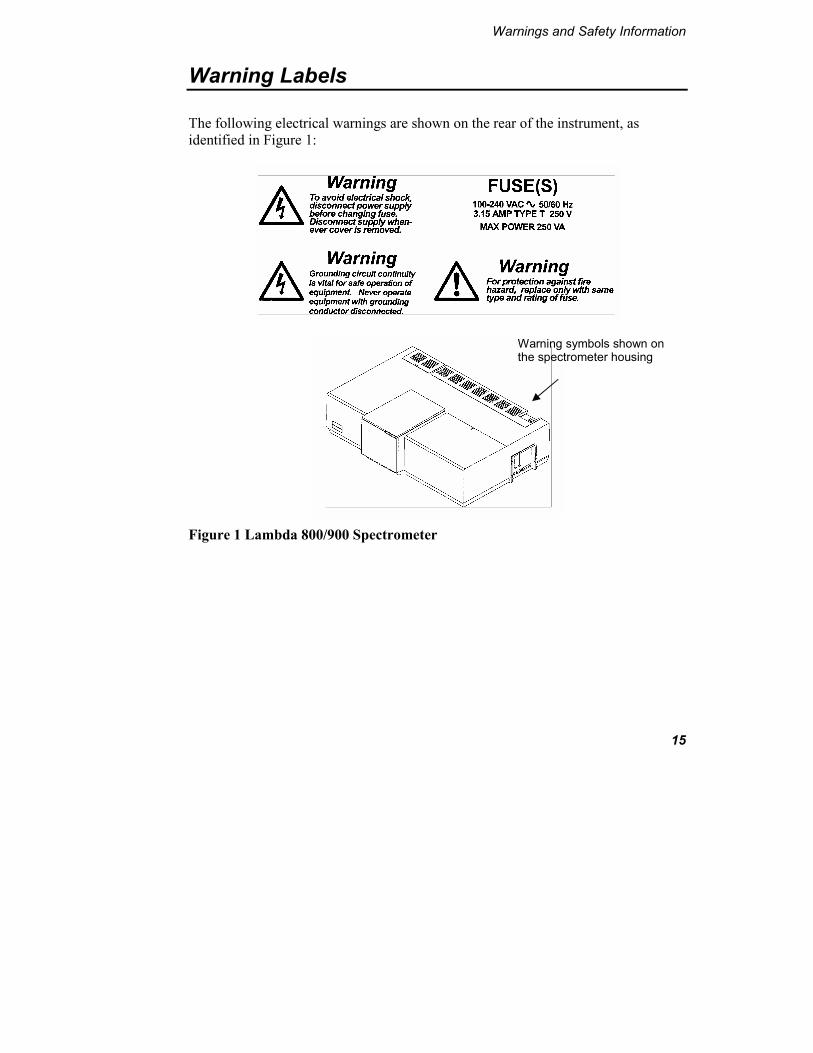
Warning Labels
The following electrical warnings are shown on the rear of the instrument, as identified in Figure 1:
Figure 1 Lambda 800/900 Spectrometer
Warning symbols shown on the spectrometer housing

Lambda 800/900 User’s Guide
16
The following warnings are shown on the inside of the lamp compartment, as identified in Figure 2:
Figure 2 Position of the lamp compartment
Lamp compartment

Introduction 2


Introduction
19
About this Manual
This manual contains the following sections:
• Warnings and Safety Information Important information on how to use the instrument safely and details of the warning labels on the instrument.
• Introduction An overview of the Lambda 800 or 900 instrument system and it’s technical specification.
• Installation How to install your instrument and the single-cell holder and general notes on installing accessories.
• Maintenance General routine maintenance procedures and details on changing lamps and fuses.
• Appendix – Translations of Warnings Local language translations of the warning signs on the instrument and used in this manual.
Conventions used in this Manual
The following conventions are used in this manual:
Normal text is used to provide information and instructions.
NOTE: indicates additional, significant information that is provided with some procedures.

Lambda 800/900 User’s Guide
20
System Description
The Lambda 800 and 900 are versatile spectrometers operating in the ultraviolet visible (UV/Vis) spectral ranges. Additionally, the Lambda 900 operates in the near infrared regions. The spectrometer features a double-beam, double monochromator, ratio recording optical system.
These instruments are usable in a wide range of applications as indicated by its performance specifications.
Figure 3 Lambda 800/900 spectrometer features
Optical System
The Lambda 800/900 Spectrometer features an all-reflecting, double-monochromator optical system. The optical components are coated with silica for durability. Holographic gratings are used in each monochromator for the UV/Vis range and the NIR range.
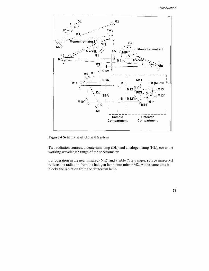
The optical system is depicted schematically in Figure 4.
Lamp compartment
Power switch
Connector panel
Sample compartment
Detector compartment
Introduction
21
Figure 4 Schematic of Optical System
Two radiation sources, a deuterium lamp (DL) and a halogen lamp (HL), cover the working wavelength range of the spectrometer.
For operation in the near infrared (NIR) and visible (Vis) ranges, source mirror M1 reflects the radiation from the halogen lamp onto mirror M2. At the same time it blocks the radiation from the deuterium lamp.
M6
SBA Dp
Detector Compartment
M11
M11΄
PM (below PbS)
M8
Sample Compartment
M13
CBM M9
M10
M10΄
C
RBA
DL
HL
Monochromator I M2
M1
M3
G2 NIR Monochromator II
FW
UV/Vis G1
M5 M7
SA
M4
NIR
UV/Vis
S
R
M12
M12΄ M13΄
M14
PbS

Lambda 800/900 User’s Guide
22
For operation in the ultraviolet (UV) range, mirror M1 is raised to permit radiation from the deuterium lamp to strike source mirror M2. Source change is automatic during monochromator slewing.
Radiation from the respective source lamp is reflected from mirror M2 via mirror M3 through an optical filter on the filter wheel assembly (FW) to mirror M4.
The filter wheel is driven by a stepping motor to be in synchronization with the monochromators. Depending on the wavelength being produced, the appropriate optical filter is located in the beam path to prefilter the radiation before it enters the monochromator. Filter change is automatic during monochromator slewing.
From mirror M4 the radiation is reflected through the entrance slit of Monochromator I. All slits are located on the slit assembly (SA). The radiation is collimated at mirror M5 and reflected to the grating table G1. Depending on the current wavelength range, the collimated radiation beam strikes either the UV/Vis grating or the NIR grating (NIR version only). The radiation is dispersed at the grating to produce a spectrum. The rotational position of the grating effectively selects a segment of the spectrum, reflecting this segment to mirror M5 and then through the exit slit. The exit slit restricts the spectrum segment to a near-monochromatic radiation beam. Grating change is automatic during monochromator slewing.
The exit slit of Monochromator I serves as the entrance slit of Monochromator II. The radiation is reflected via mirror M6 to the appropriate grating on grating table G2 and then back via mirror M6 through the exit slit to Mirror M7. The rotational position of grating table G2 is synchronized to that of G1. The radiation emerging from the exit slit exhibits high spectral purity with an extremely low stray radiation content.
In the UV/Vis and NIR range a choice is provided between a fixed slit width, a servo slit, and a slit program. When the servo slit is selected, the slit widths change automatically during scanning to maintain constant energy at the detector.
From mirror M7 the radiation beam is reflected via toroid mirror M8 to the chopper assembly (C). As the chopper rotates, a mirror segment, a window segment and two dark segments are brought alternately into the radiation beam.

Introduction
23
When a window segment enters the beam, radiation passes through to mirror M9 and is then reflected via mirror M10 to create the reference beam (R).
When a mirror segment enters the beam the radiation is reflected via mirror M10΄ to form the sample beam (S).
When a dark segment is in the beam path, no radiation reaches the detector, permitting the detector to create the dark signal.
The radiation passing alternately through the sample and reference beams is reflected by mirrors M11, M12, M13, and M11΄, M12΄, M13΄, respectively of the optics in the detector assembly onto the appropriate detector. Mirror M14 is rotated to select the required detector. A photomultiplier (PM) is used in the UV/Vis range while a lead sulfide (PbS) detector is used in the NIR range. Detector change is automatic during monochromator slewing.
At the cell plane, each radiation beam is approximately 12 mm high. The width of the radiation beams is dependent on the slit width. At a slit width of 5 nm each radiation beam is approximately 4.5 mm wide.
To permit minimum sample volumes to be measured in micro cells, the height of the radiation beam must be reduced in the active cell area.
A common beam mask (CBM) is mounted between the slit assembly (SA) and mirror M7. This mask restricts the cross-section of both the sample beam and the reference beam in the respective cell area. The radiation beam can be reduced from the maximum height of 11.7 mm to 0.0 mm in 50 steps.
During all scanning operations, the monochromators stop slewing while a filter, source, or detector change is in progress.
NOTE: You can select the source or detector change wavelength within a defined wavelength range. This facility is useful if a feature of special spectral interest is located at one of the default change wavelengths.
The spectrometer scans from higher toward lower wavelengths.
There is an optional depolarizing filter (DP) accessory, which can be swung into the beam.

Lambda 800/900 User’s Guide
24
There are attenuators, which can be swung individually into the sample beam (SBA) and the reference beam (RBA). The attenuators have the values: 0%, 1%, 10% and 100%.
Instrument Purging
Oxygen absorbs radiation in the UV range below 190 nm, while water vapor absorbs radiation in the NIR range between 1350 nm and 1450 nm, 1800 nm and 1950 nm, and also between 2520 nm and 3000 nm. Best accuracy for measurements in these spectral regions can only be obtained when the spectrometer is purged with nitrogen.
The entire optical compartment of the spectrometer is sealed. Radiation from the source lamps enters the optical compartments through a window. The sample compartment is also sealed from the optical compartment by windows. Thus the entire optical radiation path from virtually the source lamp to the detector can be purged largely free of water vapor and oxygen.
Fittings are provided on the left side of the spectrometer for connection of a supply of nitrogen. Nitrogen is conducted to the various points within the optical compartment along the conduit marked Optical and also to the sample compartment along the conduit marked SC (sample compartment). After purging these compartments the nitrogen escapes to atmosphere.
You should keep the sample compartment closed during routine operation to prevent the ingress of water vapor and oxygen. Do not leave the sample compartment cover open for longer than is necessary to perform operations within the sample compartment. After closing the sample compartment purge for several minutes before starting the measurement.
When the spectrometer has been standing for some time unpurged, an initial flow of 20 L/min is recommended. After the spectrometer has been thoroughly purged, the flow can be reduced to between 6 L/min to 7 L/min.
When you have a good deal of work in a spectral region where water vapor or oxygen absorb the radiation, we recommend that you purge the spectrometer more or less continuously. This has the advantage that startup times are markedly shorter. This advantage is somewhat offset by the increased consumption of nitrogen.

Introduction
25
Technical Data
NOTE: The Lambda 800 specifications are for UV/Vis only, specifications marked NIR do not apply.
General Type Double-beam, double monochromator, ratio recording
spectrometer for the UV/Vis/NIR ranges; with PC control.
Dimensions Width: 1020 nm Height: 300 nm Depth: 630 nm
Sample Compartment Dimensions
Width: 200 mm Height: 220 mm Depth: 300 mm
Mass 65 kg approx.
Power requirements 90 V to 250 V AC, 50/60 Hz; 400 VA
Ambient operating temperature
15 ºC to 35 ºC
Humidity range 20% to 80% relative humidity without condensation
Technical Standard In compliance with the requirements for technical instruments stipulated by IEC 1010-1/9.90
Radio interference suppression
In compliance with the legal requirements of the EMC directive 89.336/EEC (EN 50 081-1; EN 50 082-1)

Lambda 800/900 User’s Guide
26
Optics
Beam center height 90 mm above baseplate
Beam cross-section Slit Width (approx.) Height (approx.) 0.05 nm 0.04 mm x 11.7 mm 0.1 nm 0.09 mm x 11.7 mm 0.5 nm 0.45 mm x 11.7 mm 1 nm 0.89 mm x 11.7 mm 2 nm 1.00 mm x 11.7 mm 5 nm 4.44 mm x 11.7 mm measured at the focal point of the sample beam and the reference beam in the sample compartment at a wavelength of 500 nm.
Beam separation in sample compartment
126 mm
Optical pathlength in sample compartment
200 mm
Grating (Monochromator)
Holographic gratings with 1440 lines/mm UV/Vis 360 lines/mm NIR
Radiation sources Pre-aligned deuterium and halogen lamps
Detector A photomultiplier for the UV/Vis range A Peltier-cooled PbS for the NIR range
Abscissa
Wavelength range
185 to 3300 nm UV/Vis/NIR, 900 nm UV/VIS with N2 purging down to 175 nm
Wavelength accuracy
±0.08 nm UV/Vis ±0.32 nm NIR

Introduction
27
Wavelength reproducibility
<0.02 nm UV/Vis range, <0.08 nm NIR range, (0.008 nm UV/Vis range, standard deviation for 10 measurements) (0.04 nm NIR range, standard deviation for 10 measurements)
Spectral bandwidth
0.05 nm to 5.00 nm in 0.01 nm increments UV/Vis range 0.2 nm to 20 nm in 0.04 nm increments NIR range
Integration time
0.04 s to 10 s in 0.04 s increments
Ordinate
Photometric range
Transmission 0% to 200% (display range) Absorbance –6.000 to 6.000 (display range) 1 to 9999 (concentration units)
Photometric accuracy
Absorbance ±0.003; Transmission ± 0.08% at Absorbance = 1
Absorbance ±0.002; Transmission ±0.05% at Absorbance = 0.5 (measured with NIST (NBS) 930 filters)
Stray radiation Absorbance > 2 (at 200 nm with Potassium Chloride (KCl) solution)
Transmission < 0.00008% (at 220 nm, 340 nm and 370 nm; according to ASTM E-387; 1% attenuator in the reference beam)
Transmission < 0.002% (measured at 1690 nm with Chloroform (CHCl3); 4 cm pathlength)
Baseline flatness Absorbance ±0.001 (corrected; 200 nm to 3000 nm, 4 nm slit, Energy 1 NIR, 2 s integration time)

Lambda 800/900 User’s Guide
28
Noise level Absorbance < 0.00007 at 1500 nm and absorbance = 0
Absorbance < 0.000050 RMS, at 500 nm; absorbance = 0; 2 s integration time
Absorbance < 0.000300 RMS, at 500 nm; absorbance = 2; 2 s integration time
Absorbance < 0.000100 RMS, at 190 nm absorbance = 0; 2 s integration time
Absorbance Zero Stability (drift)
Absorbance < 0.0002 per hour (after warm up at 500 nm, absorbance = 0, 2 nm slit, 2 s integration time)
Data Output
Digital port One RS 232 C interface (serial), for connecting a PC
Methods
Types TimeDrive, Scan, Wavelength Program, Concentration

Installation 3


Installation
31
Overview
Figure 5 Lambda 800/900 Spectrometer
The initial installation of the spectrometer will be performed by a PerkinElmer service representative. After receipt of the instrument, please contact your PerkinElmer office or representative for further information.
If you intend to use accessories, for example a cell changer or sipper, refer to Accessory Installation on page 45 to install these accessories.
Lamp Compartment
Sample Compartment Cover
Sample Compartment Front Cover
Detector Compartment

Lambda 800/900 User’s Guide
32
Laboratory Requirements
For maximum stability and minimum maintenance observe the following requirements when choosing where to site the instrument:
• A firm base free from vibration.
• Enough space around and underneath the instrument for efficient air circulation, as shown in Figure 6.
• A constant temperature between 15 ºC and 35 ºC.
• Constant humidity between 20% and 80% relative humidity.
• An atmosphere free from dust and corrosive fumes.
• Keep out of direct sunlight. Illumination with diffuse lighting is ideal.
• A suitable source of electrical power should be located in the vicinity of the instrument, in this case a proper earth-grounded 3-wire electrical outlet. Refer to Technical Data on page 25 for the electrical ratings of the spectrometer.
• The standard sample compartment baseplates have drain holes in them to run off spilled liquids to the benchtop underneath the instrument. If required, place a sheet of thick filter paper under the instrument.

Installation
33
Figure 6 Space Requirements
Front view
Right side view
630 mm
1020 mm
300 mm

Lambda 800/900 User’s Guide
34
Unpacking and Inspection
1. Unpack the components carefully, using two people to lift the instrument itself. Keep the packing materials for possible future storage or reshipment.
CAUTION At least two people are needed to lift the instrument. The illustration below indicates where to place your hands.
Figure 7 Lifting the Instrument
2. Examine the components for any signs of damage in shipment. In the event of damage or missing parts, file an immediate claim with the authorized carrier, and inform your PerkinElmer office or representative.
Placement of hands under instrument

Installation
35
After the instrument has been unpacked, check the exterior and interior for possible damage as follows:
1. Check the entire outer cabinet of the spectrometer for damage, and make sure that terminals, fuse holders, etc. are not damaged.
2. Open and close the sample compartment cover, checking that it moves freely without binding. The compartment must be free of dust or other foreign matter.
3. Open the lamp compartment, as described in Halogen Lamp Replacement on page 70, and check for damage or loose cables.
Equipment Provided
Check that you have been shipped a Lambda 900 Spectrometer (UV/Vis/NIR) or a Lambda 800 Spectrometer, plus the components listed below, according to the order you placed:
Quantity Item Part Number
1 Software package UV WinLab B2500170
2 Single-cell holders B0505071
1 Screwdriver 5.5 mm B0142227
1 Screwdriver 4.0 mm B0126972
1 Crosshead Screwdriver B2200113
1 Connecting cable, Spectrometer to PC B0180242
1 Pack of 10 spare fuses: 3.15 A for 210 V to 240 V, or 6.3 A for 100 V to 120 V
B0155573 B0155576

Lambda 800/900 User’s Guide
36
Quantity Item Part Number
1 Line power cord or U.S.A.
B0019800 B0073775
1 Dust cover B0127401
System Configuration
Figure 8 Components of the System
• The PC and the printer may be placed either side of the spectrometer, but must not be placed on top of the spectrometer. When placing instruments side by side, always leave a small gap between them.
• Make sure that air can circulate freely over and under the system as well as behind it. Do not place anything on or under any of the components that could hinder free air circulation.
External Printer
Spectrometer PC

Installation
37
Connecting to the Line Power Supply
WARNING
Electrical Hazard • To prevent potential injury to yourself and damage to the instrument, first
make the electrical connections between the instruments in the system before connecting to the line power supply.
• The spectrometer automatically adjusts to the correct operating voltage. Before starting the instrument for the first time, make sure that the correct fuse is fitted to your line power supply. If you have a different fuse, change it for the correct one. Do not connect the spectrometer to the line power supply if the wrong fuse is fitted.
1. Make sure that the correct fuses are fitted in the holder at the rear of the spectrometer (see Changing Fuses on page 78).
Voltage Standard
100 V – 120 V 6.3 A slow-blow
210 V – 240 V 3.15 A slow-blow
NOTE: The module has two fuses.
2. Make sure that the plug fitted to the line power cord provided with the spectrometer is suitable for your local electrical outlets. If it is not, remove it and fit a plug conforming to the local regulations.
3. After all connections have been made between the various components of the system, make certain that all Power switches are set to off, then connect the line cords to the electrical power supply. The Power switch is located at the top right-hand rear of the spectrometer.

Lambda 800/900 User’s Guide
38
NOTE: To prevent interferences caused by earth loops when operating with ancillary instruments (for example, printers), connect all components of the system to the same phase of the electrical supply via a multisocket distributor.
Personal Computer
You can connect a PC to the spectrometer via the RS 232 interface.
You operate the spectrometer via the PC using the PerkinElmer UV WinLab software package. Ask your PerkinElmer service representative for more details.
Printer
You can use an external printer for hard-copy printouts of the analytical results. The printer is connected via the PC.
PerkinElmer offers suitable printers; refer to the current price list for details.

Installation
39
The Single Cell Holder
Description
There are two single-cell holders provided with the instrument, one for the sample beam and one for the reference beam. The single-cell holders are mounted on a plinth to bring them in line with the radiation beam.
Figure 9 Single Cell Holder B0505071
Installing the Cell Holder
Install the plinth in the sample compartment as follows:
1. Lower the plinth so that the two locating holes slip onto the two locating pins on the baseplate in the sample compartment, as shown in Figure 10. The plinth only fits one way round.
Locking screw for horizontal alignment
Vertical adjustment screw
Milled post Lifter
Locking screw for horizontal alignment

Lambda 800/900 User’s Guide
40
Figure 10 Fitting the plinth to the baseplate in the sample compartment
2. Screw the two thumbscrews by hand into the baseplate.
Install the single-cell holder in the sample compartment as follows:
1. Orientate the holder so that the word LAMBDA is toward the front of the sample compartment (see Figure 11 below).
2. Lower the holder so that the two locating holes slip onto the two studs on the two locating pins on the plinth in the sample compartment. The cell holder only fits one way round.
Figure 11 Lambda 800/900 Sample Compartment Baseplate
Cover Plate
Sample Holder and Plinth
Drain Hole Locating Pin
Locating Pin
Thumbscrew Thumbscrew
Locating Pin
Retaining Screw
Tube Ports

Installation
41
3. Move the milled posts a little to locate the threaded holes in the baseplate, and then tighten the milled posts. You can lead tubes and connecting cables for accessories into the sample compartment through either the tube ports, located at the front of the sample compartment, or the opening located at the left rear of the sample compartment under the cover plate. When not in use, you should always insert the caps into the tube ports and keep the cover plate fixed in place. The cover plate is fixed in place by a retaining screw.
Aligning the Single-cell Holder
Coarse alignment of the single cell holder is carried out as follows:
1. Open the sample compartment cover.
2. Fill cells with a low-absorbing solvent (deionized water or ethanol).
3. Insert one cell into the sample cell holder and one into the reference cell holder. Make certain that the cell is pushed down fully.
NOTE: The alignment procedure is for a given cell in a given holder. After alignment, the cell should always be used in the same holder.
4. Slew the monochromator to 0 nm to obtain a beam of visible (zero order) radiation in the sample compartment.
5. Block the sample and reference beam windows on the right side of the sample compartment with a card to prevent white light from saturating the detector.
6. By holding a piece of matt white paper behind each cell holder, visually examine the light spot to see that the radiation beam is passing through the cell sample area. Diffraction patterns become apparent if the radiation beam impinges on the cell wall.

Lambda 800/900 User’s Guide
42
7. If the radiation beam is not centered exactly, loosen the two locking screws and the two milled posts on the relevant cell holder and shift the cell holder plate to center the radiation beam. Then retighten the two milled posts and the two locking screws.
8. Visually check the vertical alignment of the radiation beam in the cell sample area. Alignment is correct when the radiation beam is just above the floor of the cell sample area (minimum 2 mm) or covers the cell window.
NOTE: The center of the window for micro flowcells should be ideally approximately 15 mm above the base of the cell.
Figure 12 Correct alignment of the radiation beam in the cell sample area
9. If alignment is required, turn the vertical adjustment screw on the lifter either clockwise to raise the cell, or counterclockwise to lower the cell.
10. Recheck the horizontal alignment of the radiation beam through the cell and correct if necessary.
11. Slew the monochromator to any value above 200 nm.
12. Remove the card blocking the sample beam window and close the sample compartment cover. This completes the coarse alignment of the cell holders. If necessary, proceed with the fine alignment as described below.
Min. 2 mm

Installation
43
Fine Alignment
If fine alignment is necessary, proceed as follows:
1. Slew the monochromator to your measurement wavelength or to 460 nm.
2. Call up a method that uses transmission (%T) as the ordinate.
3. If necessary change the ordinate mode to transmission.
4. Remove the reference cell from the sample compartment.
5. Make horizontal fine alignment to the sample cell holder (locking screws and milled posts loosened) to obtain the highest possible transmittance reading on the display. Close sample compartment cover while measuring transmittance.
6. Make fine alignment using the vertical adjustment screw again to obtain the highest possible reading. Close sample compartment cover while measuring transmittance.
7. When you are satisfied with the alignment, tighten the milled posts and the locking screws on the cell holder.
8. Reinstall the reference cell in the reference cell holder.
9. The sample cell remains in its holder.
10. Repeat steps 4 to 6 with the reference cell holder, but this time obtain the lowest possible transmittance reading on the display. This completes the fine alignment procedure.
NOTE: When the cell holder has been aligned once, you can take it out and reinstall it without aligning it again.

Lambda 800/900 User’s Guide
44
Minimum Volume Applications
To measure minimum sample volumes, use microcells (offered by PerkinElmer).
The minimum sample volume required is a function of the cell internal width or volume and is specified below.
Cell Type Cell Internal Width
Pathlength Minimum Volume
Required
Part Number
2 mm 1 cm 150 µL B0079404 (pair)
Height of liquid slightly more than height of beam
4 mm 1 cm 300 µL B0079402 (pair)
Cell Volume
Pathlength Minimum Volume
Required
Part Number
0.5 µL 0.01 cm 2 µL B0510076
2.5 µL 0.5 cm 5 µL B0510077
5 µL 0.1 cm 10 µL B0510078
5 µL 1.0 cm 10 µL B0505823
Cell window completely filled with liquid
30 µL 1.0 cm 50 µL B0190608
NOTE: You should align microcells very carefully in the radiation beam by following the procedures in Aligning the Single-cell Holder on page 41. When aligning microcells, fill each cell with the minimum volume of liquid specified in the above table to make sure that the liquid meniscus is not in the radiation beam.

Installation
45
Accessory Installation
NOTE: To operate the spectrometer with some accessories, for example Peltier cell changers, you need an accessory printed circuit board (PCB) fitted in the connector panel. The accessory PCB will be installed by a PerkinElmer service engineer.
WARNING
Electrical Hazard
To prevent potential injury to yourself and damage to the instrument, switch OFF all instruments in the system and disconnect them from the line power supply before you alter, or make any new, electrical connections.
This section of the manual details changes that may need to be made to the basic spectrometer before installing an accessory and an overview of the installation required for some of the specific accessories. Full procedures for installing the accessories in the spectrometer are described in the directions provided with the respective accessories.
NOTE: In the directions provided with some sample handling accessories, reference is made to earlier models in the Lambda Series of spectrometers. These directions are generally applicable to the Lambda 800 and Lambda 900.

Lambda 800/900 User’s Guide
46
Removing Parts of the Basic Spectrometer
To install certain accessories, you need to first remove different parts of the basic instrument.
Removing the Sample Compartment Cover
1. Open the cover.
2. Press the spring-loaded hinge-pin at the right side using a small screwdriver, as shown in Figure 13.
Figure 13 Spring-loaded hinge-pin
3. Lift the cover up from the right side hinge.
4. Slide the cover to the right to remove from the left side hinge. You install the sample compartment cover, or other accessory cover, by performing this procedure in reverse.
Press here

Installation
47
Removing the Sample Compartment Front Cover
1. Open the sample compartment cover.
2. Pull upwards the sample compartment front cover.
3. Lift forwards to remove. There are four catches on the front cover which fit into four locating holes at the front of the sample compartment. Install the sample compartment cover, or other accessory cover, by performing this procedure in reverse.
Removing the Sample Compartment Windows
Each window has a magnetic frame and can be carefully removed by hand. Replace the window in its original position.
Removing the Sample Compartment Baseplate
1. Open the sample compartment cover.
2. Remove the sample compartment front cover (see Removing the Sample Compartment Front Cover on page 47).
3. Undo the four thumbscrews shown in Figure 14.

Lambda 800/900 User’s Guide
48
Figure 14 Four thumbscrews on the sample compartment baseplate
4. Lift the baseplate up off the locating pins and remove it from the sample compartment. The sample compartment baseplate is installed by performing this procedure in reverse.
NOTE: The baseplate only fits one way round. The locating holes are on the underside of the baseplate.
Thumbscrews Thumbscrews

Installation
49
Removing the Sample Compartment
1. Remove the sample compartment cover and the sample compartment front cover as detailed on pages 46 and 47).
2. Remove the sample compartment baseplate as detailed on page 47.
3. Undo the four retaining screws shown in Figure 15.
Figure 15 Four retaining screws in the sample compartment
4. Lift up the sample compartment off the locating pins and remove it from the spectrometer. The sample compartment is installed by performing this procedure in reverse.
Retaining Screw
Retaining Screw
Retaining Screws
Locating Hole
Locating Slot

Lambda 800/900 User’s Guide
50
Removing the Detector Unit
WARNING
Electrical Hazard To prevent potential injury to yourself and damage to the instrument, switch OFF all instruments in the system and disconnect them from the line power supply before you alter, or make any new, electrical connections.
1. Switch off the spectrometer and disconnect the line power cord.
2. Remove the detector compartment cover by pressing down the catch and carefully pulling cover forwards until the catches are free and you can lift off the cover, as shown in Figure 16.
Figure 16 Removing the detector compartment cover
3. Undo the four thumbscrews shown in Figure 17.
Press down here
Pull here

Installation
51
Figure 17 Four thumbscrews
4. Hold the detector unit by the hand grips shown in Figure 17.
5. Carefully lift the right side up and off the locating pin. This also disconnects the integrated plug.
6. Lift the left side up and off the locating pin.
7. Move the detector unit carefully to the right and remove from the spectrometer. The detector unit is installed by performing this procedure in reverse.
Thumbscrews
Thumbscrews
Hand Grip Left Side
Hand Grip Right Side
Locating Hose Right Side

Lambda 800/900 User’s Guide
52
Removing the Lamp Unit
WARNING
Electrical Hazard High voltages are present at the lamp connectors in the lamp compartment. This is a severe electric shock hazard. Never unplug or plug in a lamp cable while power is on. Switch off the spectrometer and disconnect the line power cord before opening the lamp compartment. High Temperatures - Risk of Burns Lamps soon become very hot, make sure that the lamps and the lamp compartment have cooled to room temperature before you touch them. UV Radiation The lamps emit intense UV radiation, which can damage your eyes. Do not open the lamp compartment when the lamps are on. Do not gaze into a lighted lamp.
1. Switch off the spectrometer and disconnect the line power cord and, if necessary, wait until the lamps and lamp compartment have cooled to room temperature.
2. Remove the lamp compartment cover by pressing down the catch and carefully pushing cover to the rear until the catch is free and you can lift off the cover, as shown in Figure 18.

Installation
53
Figure 18 Removing the lamp compartment cover
NOTE: Do not touch the lamps when disconnecting them.
3. Disconnect the halogen lamp, as shown in Figure 19.
Figure 19 Halogen lamp
Press down here
Push here
Halogen Lamp Connector

Lambda 800/900 User’s Guide
54
4. Disconnect the deuterium lamp, as shown in Figure 20.
Figure 20 Deuterium lamp
5. Undo the three thumbscrews shown in Figure 21.
Figure 21 Three thumbscrews
Thumbscrews
Deuterium Lamp Connector

Installation
55
6. Lift the lamp unit off the locating pins as shown in Figure 22.
Figure 22 Lamp unit locating hole and slot
7. Place the lamp unit carefully on the bench behind the spectrometer.
8. Disconnect the stepping motor connector, as shown in Figure 23.
Figure 23 Stepping motor connector
Locating Hole Locating Slot
Lamp Unit
Keyed Connector for the Stepping Motor

Lambda 800/900 User’s Guide
56
Purge Gas Connectors
There are two nipples located on the left side of the spectrometer to connect to a purge gas supply. The connectors are marked SC for the sample compartment, and Optics for the optical compartments, as shown in Figure 24.
Figure 24 Connectors for the purge gas supply
For initial purging, a gas flow of 20 l/min is recommended. After the spectrometer has been thoroughly purged, a flow of between 6 L/min to 7 L/min is sufficient.
NOTE: A Nitrogen Purge Accessory Kit, comprising of a filter and a flow controller with flowmeter, is offered as an option. With this kit you can control the gas flow more accurately.
Installation
57
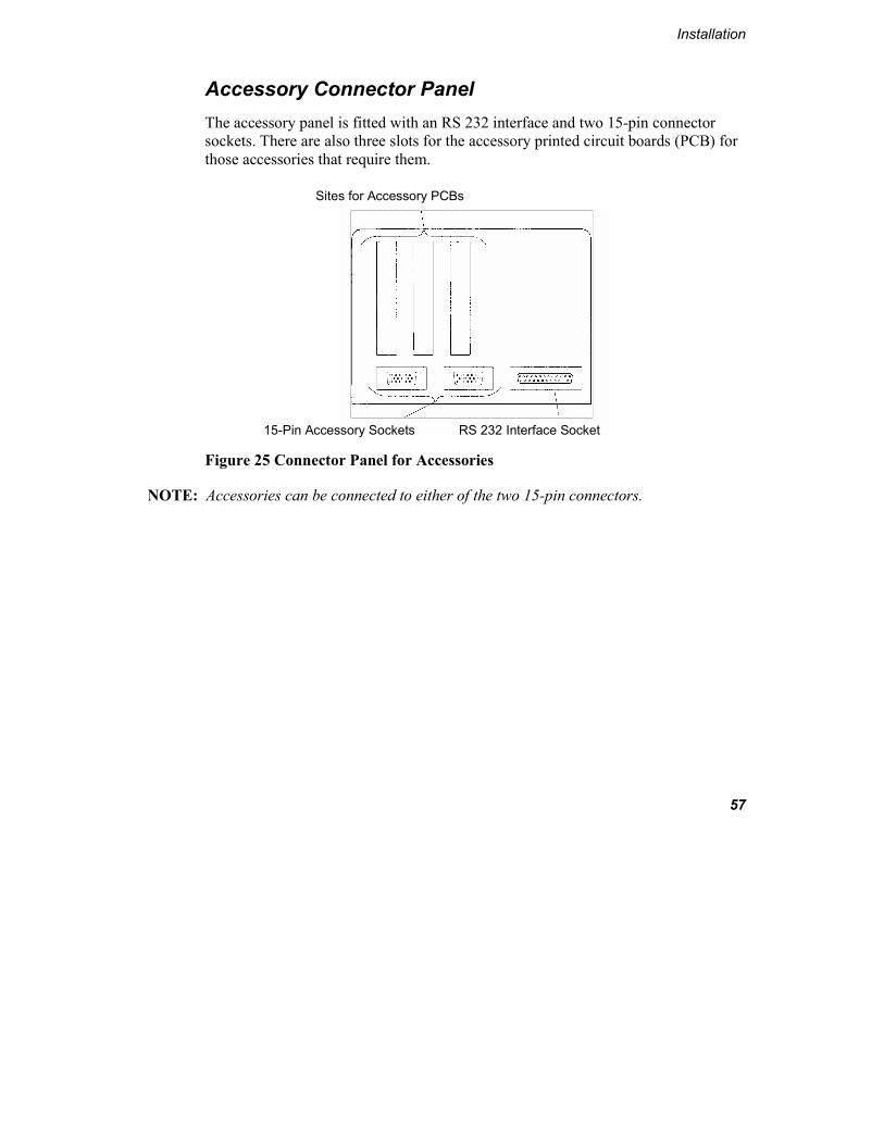
Accessory Connector Panel The accessory panel is fitted with an RS 232 interface and two 15-pin connector sockets. There are also three slots for the accessory printed circuit boards (PCB) for those accessories that require them.
Figure 25 Connector Panel for Accessories
NOTE: Accessories can be connected to either of the two 15-pin connectors.
Sites for Accessory PCBs
15-Pin Accessory Sockets RS 232 Interface Socket

Lambda 800/900 User’s Guide
58
Accessory Connections Overview
Figure 26 Accessories for the Lambda 800/900
Peltier Cell Holder
Peltier Cell Changer
Temperature Sensor
Automatic Cell Changer
Sipper
External Printer
PC

Installation
59
Specific Accessory Installation Overviews
Automatic Cell Changers
Connector on Spectrometer: 15-pin connector
Installation: See cell changer manual
Cables: Lead through bottom of spectrometer housing
Tubes: Lead through bottom of spectrometer housing
Sample Compartment Cover: Unchanged
Alignment: See cell changer manual
Temperature Sensor
Connector on Spectrometer: Slot in accessory board
Installation: See temperature sensor description
Cables: Lead through the tube ports
Sample Compartment Cover: Unchanged
NOTE: When connecting the temperature sensor, align the red mark on the plug with the red mark on the socket. Pull back the collar on the plug to connect/disconnect the plug. Release the collar to secure the plug.

Lambda 800/900 User’s Guide
60
Sippers
Connector on Spectrometer: 15-pin connector
Installation: See sipper manual
Cables: See sipper manual
Tubes: See sipper manual
Sample Compartment Cover: Install sample compartment front cover for sipper
Figure 27 Sipper, electrical connection
Pin Configuration
There are two 15-pin connectors fitted to the connector panel of the Lambda 800/900 spectrometer to connect accessories. The connectors are identically configured so that the accessories can be connected to any of them. The pin numbering is shown in Figure 28, and the configuration is given in the following table.
Sipper
Spectrometer Connector Panel

Installation
61
Figure 28 Pin configuration of 15-pin connector
Pin Configuration Description
1 GND D Ground (Digital) logic
2 +5 V Logic power supply
3 Not used
4 GND P Ground Power
5 +24 V Power Supply
6 Not used
7 Not used
8 Not used
9 Not used
10 Not used
11 +12 V Analog power supply
12 GND A Ground Analog
13 -12 V Analog power supply
14 SCL Serial clock
15 SDA Serial data

Lambda 800/900 User’s Guide
62

Maintenance 4


Maintenance
65
General Maintenance
Maintenance procedures that you can perform yourself are described in this chapter.
NOTE: A PerkinElmer service representative or similarly authorized person should perform all internal servicing of the instrument. Please contact your local PerkinElmer sales or service office to obtain service.
WARNING
Unauthorized Adjustments and Servicing Do not attempt to make adjustments, replacements or repairs to this instrument except as described in the accompanying User Documentation.Only a PerkinElmer service representative or similarly trained and authorized person should be permitted to service the instrument.
Daily Care
The instrument is constructed with high quality components and requires little maintenance other than to keep it clean and free of dust.
To protect the optical system from dust and fumes, you should keep the sample compartment cover closed except for when you are carrying out work in the compartment.
The sample compartment windows should always be installed.

Lambda 800/900 User’s Guide
66
You should observe the following care routine to maintain your instrument in good condition:
• Immediately clean all spilled materials from the affected area and wipe it dry with lint free paper or cloth. If you have to wipe the sample compartment windows, make sure you do not introduce scratches. The windows are optical components and you should handle them in the sampe way as high quality cells.
• Do not leave samples, particularly those given to fuming or evaporation, in the sample compartment for longer than necessary.
• If any type of sample handling system is installed and portions of it are left in the sample compartment (such as a sipper and flowcell), make certain that the system is cleaned at the end of the working day. Generally, such systems should be filled with deionized water when left overnight.
CAUTION
Spills Take care not to spill liquids onto the spectrometer. Expensive damage can result to the optics or electronics if liquids are spilled and run inside the instrument.
Cleaning the Sample Compartment
You must clean the sample compartment every time anything is spilled into it. This preserves the matt black finish, and prevents corrosion and contamination.
The standard sample compartment baseplates have drain holes, as shown in Figure 29, in them to run off spilled liquids to the benchtop underneath the instrument. If required, place a sheet of thick filter paper under the instrument.

Maintenance
67
Figure 29 Drain holes in standard sample compartment baseplate
1. First remove the cell holder or other sample handling accessory from the sample compartment.
2. Using a soft cloth and mild laboratory detergent solution, lightly scrub away all foreign material.
3. Using a clean cloth dampened with water, rinse the cleaned surfaces thoroughly.
4. Dry with lint free cloth or tissue.
Drain Holes

Lambda 800/900 User’s Guide
68
Sample Compartment Windows
Four windows are provided with the spectrometer. The windows are made of silica and may be used in the entire spectral range of the spectrometer.
The windows seal the sample compartment and thus protect the instrument’s optics from dust and fuming or aggressive samples.
• Generally, the windows should be installed at all times.
• The windows are an optical component and require the same care and handling as cells.
• The windows can be removed to clean them. Each window has a magnetic frame and can be carefully removed by hand. Windows are most suitably cleaned by wiping them with a soft cloth moistened with ethanol. Replace the window in its original position after cleaning.
Use and Care of Cells
A good spectrometer cell is an optical device, forming a part of the optical system of the instrument with which it is used. It must be accorded the same careful treatment applied to any optical component. Optical faults of a minor nature, scratches, lint, finger marks, etc. on the optical surfaces can easily introduce substantial analytical errors.
You should observe the following list of cell handling rules to prevent analytical errors and to achieve utmost precision:
• Only hold cells by non-optical surfaces, such as the matt finish surfaces.
• Protect cells from scratches, and never permit them to rub against one another or against other hard surfaces.
• Avoid abrasive, corrosive or stain-producing cleaning agents, and make certain that the exposed surfaces of cells are optically clean.

Maintenance
69
• Always wipe the optical surfaces of cells dry and free of finger marks, using a soft cloth or cleaning tissue, just before placing them in the cell holder.
• When measuring cold solutions, always bear in mind that condensation can form on the optical surfaces.
• Make certain no bubbles cling to the inner surfaces of the cell, particularly when handling cold solutions.
• For maximum precision and accuracy, calibrate and test with cells of the same type, and always insert cells into the holders with the same orientation.

Lambda 800/900 User’s Guide
70
Replacing a Lamp
The source lamps are located in the lamp compartment at the top left rear of the spectrometer, as shown in Figure 30.
Figure 30 Lamp compartment
Halogen Lamp Replacement
If the lamp burns out, or if the bulb becomes blackened after prolonged use, you should replace the lamp. Replacement lamp assemblies (B0114620) are provided complete with pre-aligned mounts.
Lamp compartment

Maintenance
71
Figure 31 Pre-aligned Halogen Lamp
WARNING
Electrical Hazard High voltages are present at the lamp connectors in the lamp compartment – severe electric shock hazard. Never unplug or plug in a lamp cable while power is ON. Switch off the spectrometer and remove the plug from the electrical supply before starting with the replacement. High Temperatures - Risk of Burns Lamps soon become very hot, make sure that the lamps and the lamp compartment have cooled to room temperature before you touch them.. UV Radiation The lamps emit intense UV radiation which can damage your eyes. Do not open the lamp compartment when the lamps are on. Do not gaze into a lighted lamp.
1. Switch off the spectrometer and disconnect the line power cord, if necessary wait until the lamps and lamp compartment have cooled to room temperature.

Lambda 800/900 User’s Guide
72
2. Remove the lamp compartment cover by pressing down the catch and carefully pushing the cover to the rear until the catch is free, as shown in Figure 32, then you can lift off the cover.
Figure 32 Removing lamp compartment cover
3. Remove the lamp baffle by slackening the thumbscrew for the deuterium lamp and lifting the lamp baffle vertically upward, as shown in Figure 33.
Figure 33 Removing the lamp baffle
Lamp baffle Thumbscrew (deuterium lamp)
Press down here
Push here

Maintenance
73
4. Carefully pull the halogen lamp connector from the rear of the halogen lamp, as shown in Figure 34.
Figure 34 Removing the halogen lamp connector
5. Remove the halogen lamp assembly from the bracket by slackening the thumbscrew and pulling the lamp mount vertically upward. Save the thumbscrew for use with the new lamp assembly.
6. Unpack the new lamp assembly, taking care to hold it only by the metal mount to prevent finger marks on the bulb.
7. Slip the slot at the base of the lamp mount over the stud on the bracket in the lamp compartment and then secure with the thumbscrew.
8. Carefully push the halogen lamp connector firmly onto the pins on the base of the halogen lamp.
9. Wipe the halogen lamp bulb with a soft cloth moistened with alcohol to remove dirt, since this would otherwise be burned in when the lamp is hot.
10. Replace the lamp compartment cover. This completes the halogen lamp replacement procedure.
Thumbscrew (halogen lamp)
Halogen lamp connector
Halogen lamp assembly

Lambda 800/900 User’s Guide
74
NOTE: Due to the pre-aligned mounts, the alignment of lamps after installation is generally so good that further alignment is not required.
Deuterium Lamp Replacement
If the lamp burns out, or indicates falling energy after prolonged use, you should replace the lamp. Replacement lamp assemblies (B0160917) are provided complete with pre-aligned mounts.
Figure 35 Pre-aligned Deuterium Lamp Assembly (B0160917)
NOTE: An operating hours counter is incorporated in the red deuterium lamp lead. By means of a gap between the two display bars it is possible to read off the number of hours that the lamp has been in operation. One scale division corresponds to approximately 100 hours.
Operating Hours Counter

Maintenance
75
WARNING
Electrical Hazard High voltages are present at the lamp connectors in the lamp compartment – severe electric shock hazard. Never unplug or plug in a lamp cable while power is ON. Switch off the spectrometer and remove the plug from the electrical supply before starting with the replacement. High Temperatures - Risk of Burns Lamps soon become very hot, make sure that the lamps and the lamp compartment have cooled to room temperature before you touch them. UV Radiation The lamps emit intense UV radiation which can damage your eyes. Do not open the lamp compartment when the lamps are on. Do not gaze into a lighted lamp.
1. Switch off the spectrometer and disconnect the line power cord, if necessary wait until the lamps and lamp compartment have cooled to room temperature.
2. Remove the lamp compartment cover by pressing down the catch and pushing the cover to the left, as shown in Figure 36.
Figure 36 Removing the lamp compartment cover
Press down here
Push here

Lambda 800/900 User’s Guide
76
3. Remove the lamp baffle by slackening the thumbscrew for the deuterium lamp, shown in Figure 37, and lifting the lamp baffle vertically upward.
Figure 37 Removing the lamp baffle
4. Unplug the deuterium lamp connector by squeezing in the two lugs at each side of the connector and carefully pulling the connector vertically upward.
Figure 38 Removing the deuterium lamp connector
Lamp baffle
Thumbscrew (deuterium lamp)
Deuterium lamp connector
Deuterium lamp assembly
Thumbscrew

Maintenance
77
5. Remove the lamp assembly from the bracket by slackening the thumbscrew and pulling the lamp mount vertically upward. Save the thumbscrew for use with the new lamp assembly.
6. Unpack the new lamp assembly, taking care to hold it only by the metal mount to prevent finger marks on the lamp window.
7. Slip the slot at the base of the lamp mount over the stud on the bracket in the lamp compartment and then secure with the thumbscrew.
8. Plug the deuterium lamp connector into the socket.
NOTE: The socket in the lamp compartment is asymmetric; the deuterium lamp connector can be inserted in one direction only. Make certain that the connector is the right way round before inserting it. Never attempt to insert the connector by force.
9. Wipe the lamp window with a soft cloth moistened with alcohol to remove dirt, since this would otherwise be burned in when the lamp is hot.
10. Replace the lamp compartment cover. This completes the deuterium lamp replacement procedure.
NOTE: Due to the pre-aligned mounts, the alignment of lamps after installation is generally so good that further alignment is not required.

Lambda 800/900 User’s Guide
78
Changing Fuses
WARNING
Electrical hazard To prevent potential injury to yourself and damage to the instrument, switch OFF all instruments in the system and disconnect them from the line power supply before you alter, or make any new, electrical connections.
The fuses are located in a fuse holder at the rear of the instrument, as shown in Figure 39.
Figure 39 Rear view, fuse holder
1. Switch off the instrument and remove the line power cord from the electrical supply.
2. Squeeze the two lugs at each side of the fuse holder and gently pull out.
Figure 40 Removing the fuse holder
Fuse Holder
Fuse Holder

Maintenance
79
3. Replace the fuses with a new ones of the same type and rating:
Voltage Standard
100 V – 120 V 6.3 A slow-blow
210 V – 240 V 3.15 A slow-blow
NOTE: The module has two fuses and should always replace both at the same time, even if only one blew, as the other may have been weakened.
4. Replace the fuse holder by aligning the lug at the bottom of the fuse holder with the slot in the socket. A click is heard as each lug snaps into place.
NOTE: If you use the correct fuses but the instrument still does not work correctly, or the fuses blow repeatedly, contact your PerkinElmer office or representative.

Lambda 800/900 User’s Guide
80
Replacement Parts
Supplies, accessories, and replacement parts can be ordered directly from PerkinElmer. e-ssentials, PerkinElmer’s catalog service, offers a full selection of high-quality ultraviolet, fluorescence, and polarimetry supplies through the Supplies Catalog for Ultraviolet/Visible and Fluorescence Spectroscopy and Polarimetry.
To place an order, request a free catalog, or ask for information:
If you are located within the U.S., call toll free 1-800-762-402, 8 a.m. to 8 p.m. EST. Your order will be shipped promptly, usually within 24 hours.
If you are located outside of the U.S., call your local PerkinElmer sales office.
Accessories, spares and other parts and information are available on-line at essentials.perkinelmer.com.
Quantity Item Part Number
1 Pack of 10 fuses 3.15 A slow-blow B0155573
1 Pack of 10 fuses 6.3 A slow-blow B0155576
1 RS 232 printer cable B0166569
1 Deuterium Lamp, pre-aligned B0160917
1 Halogen Lamp, pre-aligned B0114620
1 Thumbscrew for lamp mount B0119371
1 Set of Sample Compartment Windows B0505982
1 Single Cell Holder B0505071

Appendix - Translations of
Warnings 5


Appendix - Translations of Warnings
83
Translations of Warnings
This appendix contains translations of the warnings shown on the instrument and used in this manual.

Lambda 800/900 User’s Guide
84
Appendix - Translations of Warnings
85

Lambda 800/900 User’s Guide
86

Appendix - Translations of Warnings
87

Lambda 800/900 User’s Guide
88

Appendix - Translations of Warnings
89

Lambda 800/900 User’s Guide
90

Index


Index
93
Index
A
Accessory........................................60 Accessory installation.....................45
Automatic Cell Changers............59 Sippers ........................................60 Temperature Sensor ....................59
Accessory panel ..............................57 Automatic cell changers Installation)
....................................................59
C
Cells Care and handling.......................68
Connecting to the Line Power Supply ...........37 to the PC .....................................38 to the printer................................38
D
Detector Removing....................................50
Deuterium lamp Replacement ...............................74
E
Electrical Safety................................8 Equipment Provided .......................35
F
Fuses Replacement ...............................78
G
Graphic symbols used on the instrument................................... 15
H
Halogen lamp Replacement ............................... 70
I
Inspection ....................................... 35 Installation ...................................... 31
Accessories................................. 45 Single-Cell Holder...................... 39
L
Laboratory environment ........... 12, 32 Lamps
Removing the unit ...................... 52 Replacing.................................... 70
M
Maintenance ................................... 65 Cleaning the Sample Compartment
................................................ 66 Daily Care................................... 65 Replacement parts ...................... 80 Replacing a Lamp....................... 70 Replacing fuses........................... 78 Use and Care of Cells ................. 68
Manual conventions ....................... 19 Microcells....................................... 44

Lambda 800/900 User’s Guide
94
O
Optical system description..............20
P
PC (connecting) ..............................38 Pin connectors...........................57, 60 Power supply ..................................37 Printer (connecting) ........................38 Purging............................................24
Connectors ..................................56
R
Removing Detector unit ...............................50 Lamp unit....................................52 Sample compartment ..................49 Sample compartment baseplate ..47 Sample compartment cover ........46 Sample compartment front cover47 Sample compartment windows...47
S
Safety Information............................7 Environment ...............................12
Sample compartment Cleaning......................................66 Removing....................................49 Removing the baseplate..............47 Removing the cover....................46
Removing the front cover........... 47 Removing the windows .............. 47 Windows..................................... 68
Single-cell holder Alignment................................... 41 Description ................................. 39 Fine alignment............................ 43 Installation .................................. 39 Microcells................................... 44
Sippers installation ......................... 60 Spare parts ...................................... 80 System Configuration..................... 36 System Description......................... 20
Instrument Purging ..................... 24 Optical System ........................... 20
System overview ............................ 31
T
Technical Data................................ 25 Temperature sensor installation...... 59 Translations of Warnings ............... 83
U
Unpacking ...................................... 34 UV Radiation safety ....................... 14
W
Warning labels................................ 15 Translations ................................ 83