lab on a chip - biophot.caltech.edu · smartphone microscope can be a good fit for outdoor imag-ing...
TRANSCRIPT

Lab on a Chip
Publ
ishe
d on
27
May
201
4. D
ownl
oade
d by
Sta
nfor
d U
nive
rsity
on
25/0
6/20
14 1
8:43
:14.
PAPER View Article OnlineView Journal
This journal is © The Royal Society of Chemistry 2014
aDepartment of Electrical Engineering, California Institute of Technology,
1200 E. California Blvd. Pasadena, CA 91125, USA. E-mail: [email protected];
Fax: +1 626 395 3786; Tel: +1 626 395 2258bDepartment of Bioengineering, Department of Medical Engineering, California
Institute of Technology, 1200 E. California Blvd., Pasadena, CA 91125, USA
† Electronic supplementary information (ESI) available: Fig. S1–S4, Movies S1–S2.See DOI: 10.1039/c4lc00523f
Cite this: DOI: 10.1039/c4lc00523f
Received 2nd May 2014,Accepted 27th May 2014
DOI: 10.1039/c4lc00523f
www.rsc.org/loc
A smartphone-based chip-scale microscope usingambient illumination†
Seung Ah Lee*a and Changhuei Yangab
Portable chip-scale microscopy devices can potentially address various imaging needs in mobile
healthcare and environmental monitoring. Here, we demonstrate the adaptation of a smartphone's
camera to function as a compact lensless microscope. Unlike other chip-scale microscopy schemes,
this method uses ambient illumination as its light source and does not require the incorporation of a
dedicated light source. The method is based on the shadow imaging technique where the sample is
placed on the surface of the image sensor, which captures direct shadow images under illumination. To
improve the image resolution beyond the pixel size, we perform pixel super-resolution reconstruction
with multiple images at different angles of illumination, which are captured while the user is manually
tilting the device around any ambient light source, such as the sun or a lamp. The lensless imaging
scheme allows for sub-micron resolution imaging over an ultra-wide field-of-view (FOV). Image acquisi-
tion and reconstruction are performed on the device using a custom-built Android application,
constructing a stand-alone imaging device for field applications. We discuss the construction of the
device using a commercial smartphone and demonstrate the imaging capabilities of our system.
Introduction
Microscopes are among the most commonly used equipmentin biology and medicine, yet the size and the cost of thesemicroscopes limit its applications in the field setting. For thisreason, portable microscopic imaging systems are in highdemand, especially for global healthcare and environmentalmonitoring. For example, diagnostics of many third-worlddiseases, such as water-borne parasite infections, blood-borne diseases and bacterial infections, requires microscopicinspection of bodily fluids or cell/tissue samples.1–6 Also,microscopic analysis of an environmental specimen is a cru-cial step in water quality monitoring and environmentalpathogen screening.7 A low-cost, light-weight portable imag-ing system with network connectivity can greatly improve andsimplify the way these tests are conducted in the field.
Recent advances in smartphone technology are having atransformative impact on global healthcare and remotesensing. Smartphone penetration is expected to surpass60% of the global population by the end of 2019.8 Modern
smartphones deploy high computing power comparable to per-sonal computers, high-speed mobile network connectivity andcomplex sensor technologies, all integrated in a palm-sizedgeometry. In particular, camera modules in smartphonesemploy state-of-the-art image sensors with small pixel sizesand high pixel counts, currently up to 40 megapixels. Micro-scopes using these built-in camera modules allow for a com-pact and portable digital imaging platform ideal for fieldapplications. In addition, the connectivity of these mobiledevices opens up various opportunities for telemedicine andremote diagnostics in resource-limited settings.9–11
Much effort has been demonstrated to construct a com-pact microscope on mobile devices. One of the initialapproaches was to add an objective lens atop of a cameramodule of a mobile phone.12 These imaging systems can beattached to any mobile phones without modification of thedevice, realizing low-cost microscopes for the masses. Theperformance of these microscopes is determined by thedesign of the optical systems, where increased resolutionmay result in a limited field-of-view (FOV). As an alternativeapproach, lensfree microscopes on mobile phones based ondigital inline holography have been demonstrated.13 Thesemicroscopes computationally render images of the targetobjects by interferometry under controlled illumination andcan achieve a low-cost and light-weight configuration idealfor field applications. Recently, a smartphone-based contactmicroscope has been developed to image dense or connected
Lab Chip
Lab on a ChipPaper
Publ
ishe
d on
27
May
201
4. D
ownl
oade
d by
Sta
nfor
d U
nive
rsity
on
25/0
6/20
14 1
8:43
:14.
View Article Online
samples without holographic reconstruction, with the attach-ment of a tapered fibre-optic array over the camera module.14
Here, we report on a smartphone-based chip-scale micro-scope in a lens-free and light-source-free configuration. Ourdevice follows a contact imaging scheme where the sample ismounted directly on top of the image sensor and uses anambient light source rather than a dedicated light source forillumination. To improve image resolution beyond the pixelsize, we rely on the user's hand motion to manually tilt thedevice around the light source, such as the sun or a lamp, tocapture multiple images with various illumination angles,which are then processed with the pixel super-resolutionalgorithm. This scheme eliminates the illumination design aswell as the lenses, thus allowing for a simple, low-cost andcompact configuration that is only composed of an imagesensor. Image acquisition and reconstruction are performedon a custom-built Android application, constructing a stand-alone portable imaging device for field applications.
The imaging scheme based on manual angular scanningand pixel super-resolution reconstruction is a derivationof chip-scale microscopy techniques that have been previ-ously demonstrated by our group.15–18 The general strategyof our chip-scale microscopes requires the sample to beplaced on the surface of the image sensor. The shadow imagecasted by the sample upon illumination is collected with theresolution determined by the sensor's pixel size. We thenimprove the image resolution via pixel super-resolutionimage reconstruction using multiple low resolution imagestaken with sub-pixel shifts between each frame. In our previ-ous work (sub-pixel perspective sweeping microscopy,SPSM),16,19 we have used moving light sources, such as thebright pixels in a smartphone screen or a light emitting diode(LED) matrix, which create sub-pixel shifted shadows on thedetector surface. The basic concept of our smartphone micro-scope is similar to that of SPSM but with further simplifica-tion of the device by manual scanning under ambient lightas illumination.
Direct shadow imaging does not impose strict require-ments on both the illumination and the sample and thusany incoherent light sources with a broad spectrum can beused. We can image contiguously connected samples suchas confluent cell cultures and high-density smear films,thus the biological sample can be prepared at the same con-centration as in conventional microscopy slides. In addition,image reconstruction using the pixel super-resolution algo-rithm does not require high computing power and can beperformed on smartphone processors. For these reasons, ourchip-scale imaging technique holds a solid ground for appli-cations in mobile microscopy.
In the following section, we will demonstrate the workingprinciple of our smartphone microscope and showcase theperformance of our prototype device. With a compact config-uration and robust performance, we envision that oursmartphone microscope can be a good fit for outdoor imag-ing applications where the user can perform microscopyimaging with ambient illumination.
Lab Chip
Methods
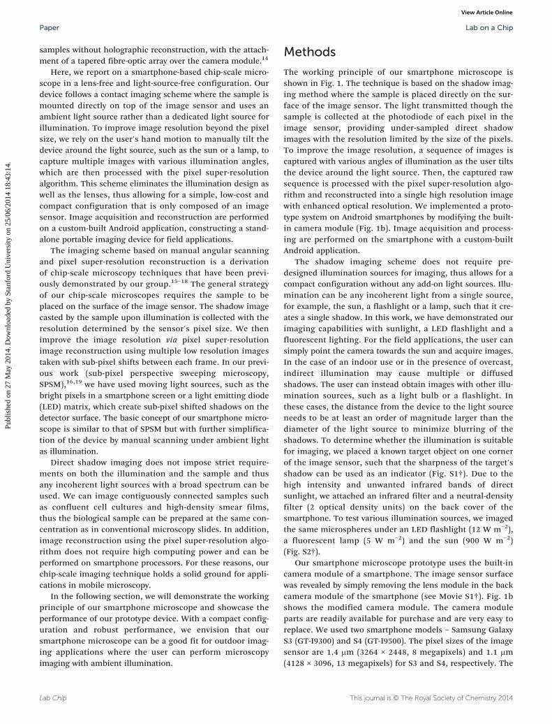
The working principle of our smartphone microscope isshown in Fig. 1. The technique is based on the shadow imag-ing method where the sample is placed directly on the sur-face of the image sensor. The light transmitted though thesample is collected at the photodiode of each pixel in theimage sensor, providing under-sampled direct shadowimages with the resolution limited by the size of the pixels.To improve the image resolution, a sequence of images iscaptured with various angles of illumination as the user tiltsthe device around the light source. Then, the captured rawsequence is processed with the pixel super-resolution algo-rithm and reconstructed into a single high resolution imagewith enhanced optical resolution. We implemented a proto-type system on Android smartphones by modifying the built-in camera module (Fig. 1b). Image acquisition and process-ing are performed on the smartphone with a custom-builtAndroid application.
The shadow imaging scheme does not require pre-designed illumination sources for imaging, thus allows for acompact configuration without any add-on light sources. Illu-mination can be any incoherent light from a single source,for example, the sun, a flashlight or a lamp, such that it cre-ates a single shadow. In this work, we have demonstrated ourimaging capabilities with sunlight, a LED flashlight and afluorescent lighting. For the field applications, the user cansimply point the camera towards the sun and acquire images.In the case of an indoor use or in the presence of overcast,indirect illumination may cause multiple or diffusedshadows. The user can instead obtain images with other illu-mination sources, such as a light bulb or a flashlight. Inthese cases, the distance from the device to the light sourceneeds to be at least an order of magnitude larger than thediameter of the light source to minimize blurring of theshadows. To determine whether the illumination is suitablefor imaging, we placed a known target object on one cornerof the image sensor, such that the sharpness of the target'sshadow can be used as an indicator (Fig. S1†). Due to thehigh intensity and unwanted infrared bands of directsunlight, we attached an infrared filter and a neutral-densityfilter (2 optical density units) on the back cover of thesmartphone. To test various illumination sources, we imagedthe same microspheres under an LED flashlight (12 W m−2),a fluorescent lamp (5 W m−2) and the sun (900 W m−2)(Fig. S2†).
Our smartphone microscope prototype uses the built-incamera module of a smartphone. The image sensor surfacewas revealed by simply removing the lens module in the backcamera module of the smartphone (see Movie S1†). Fig. 1bshows the modified camera module. The camera moduleparts are readily available for purchase and are very easy toreplace. We used two smartphone models – Samsung GalaxyS3 (GT-I9300) and S4 (GT-I9500). The pixel sizes of the imagesensor are 1.4 μm (3264 × 2448, 8 megapixels) and 1.1 μm(4128 × 3096, 13 megapixels) for S3 and S4, respectively. The
This journal is © The Royal Society of Chemistry 2014
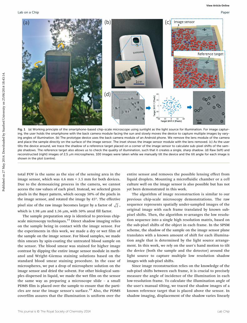
Fig. 1 (a) Working principle of the smartphone-based chip-scale microscope using sunlight as the light source for illumination. For image captur-ing, the user holds the smartphone with the back camera module facing the sun and slowly moves the device to capture multiple images by vary-ing angles of illumination. (b) The prototype device uses the back camera module of an Android phone. We remove the lens module of the cameraand place the sample directly on the surface of the image sensor. The inset shows the image sensor module with the lens removed. (c) As the usertilts the device around, we trace the shadow of a reference target placed on a corner of the image sensor to calculate sub-pixel shifts of the sam-ple shadows. The reference target also allows us to check the quality of illumination, such that it creates a single, sharp shadow. (d) Raw (left) andreconstructed (right) images of 2.5 μm microspheres. 100 images were taken while we manually tilt the device and the tilt angle for each image isshown in the plot (centre).
Lab on a Chip Paper
Publ
ishe
d on
27
May
201
4. D
ownl
oade
d by
Sta
nfor
d U
nive
rsity
on
25/0
6/20
14 1
8:43
:14.
View Article Online
total FOV is the same as the size of the sensing area in theimage sensor, which was 4.6 mm × 3.5 mm for both devices.Due to the demosaicing process in the camera, we cannotaccess the raw values of each pixel. Instead, we selected greenpixels in the Bayer pattern, which occupy 50% of the pixels inthe image sensor, and rotated the image by 45°. The effective
pixel size of the raw image becomes larger by a factor of 2 ,which is 1.98 μm and 1.56 μm, with 50% areal fill factor.
The sample preparation step is identical to previous chip-scale microscopy techniques.19 Direct shadow imaging relieson the sample being in contact with the image sensor. Forthe experiments in this work, we made a dry or wet film ofthe sample on the image sensor. For blood samples, we madethin smears by spin-coating the untreated blood sample onthe sensor. The blood smear was stained for higher imagecontrast by dipping the entire image sensor module in meth-anol and Wright–Giemsa staining solutions based on thestandard blood smear staining procedure. In the case ofmicrospheres, we put a drop of microsphere solution on theimage sensor and dried the solvent. For other biological sam-ples dispersed in liquid, we made the wet film on the sensorthe same way as preparing a microscope slide – a smallPDMS film is placed over the sample to ensure that the parti-cles are near the image sensor's surface.19 Also, the PDMScoverfilm assures that the illumination is uniform over the
This journal is © The Royal Society of Chemistry 2014
entire sensor and removes the possible lensing effect fromliquid droplets. Mounting a microfluidic chamber or a cellculture well on the image sensor is also possible but has notyet been demonstrated in this work.
The algorithm of image reconstruction is similar to ourprevious chip-scale microscopy demonstrations. The rawsequence represents spatially under-sampled images of theoriginal image with each frame translated by known sub-pixel shifts. Then, the algorithm re-arranges the low resolu-tion sequence into a single high resolution matrix, based onthe sub-pixel shifts of the object in each frame. In the SPSMscheme, the shadow of the sample on the image sensor planetranslates with a known amount of shift for each illumina-tion angle that is determined by the light source arrange-ment. In this work, we rely on the user's hand motion to tiltthe device (both the sample and the detector) around thelight source to capture multiple low resolution shadowimages with sub-pixel shifts.
Since image reconstruction relies on the knowledge of thesub-pixel shifts between each frame, it is crucial to preciselymeasure the angle of incidence of the illumination in eachlow-resolution frame. To calculate the illumination angle ofthe user's manual tilting, we traced the shadow images of aknown reference target that is placed above the sensor. Inshadow imaging, displacement of the shadow varies linearly
Lab Chip

Lab on a ChipPaper
Publ
ishe
d on
27
May
201
4. D
ownl
oade
d by
Sta
nfor
d U
nive
rsity
on
25/0
6/20
14 1
8:43
:14.
View Article Online
with the distance between the sample and the object. Theactual sample is usually located within a few-micrometrerange from the sensor surface (depending on the size of thesample), thus the sub-pixel shifts of the sample shadow canbe scaled from the shift of the reference shadow. When thereference object is placed at a longer distance away from thesensor, the reference shadow moves in a longer displacementand the accuracy of the measurement increases. However, iftoo far, the reference shadow becomes blurry due to diffrac-tion and the tracking of the shadow may fail due to the lowcontrast of the target shadow images. For the reference tar-get, we placed a piece of 200 μm-thick transparent film witha cross-pattern (200 μm × 200 μm) printed on one side. Thefilm is placed such that the printed target pattern facestowards the illumination source (Fig. 1c).
Fig. 1d shows raw and improved high resolution images of2.5 μm microspheres imaged with a 1.4 μm-pixel sensor. Notethat the bright centre of each microsphere is resolved in theimproved image as oppose to the low resolution image. We used100 images to perform 8 × 8 enhancement by rounding the sub-pixel shifts to integer multiples of 1/8 of a low resolution pixel.
Fig. 2 shows the workflow of the image acquisition. Theuser starts the application and opens the camera to start cap-turing of images. The user is advised to point the cameratowards the light source and tilt the camera in all directions.As the images are captured, the application calculates in real-time the tilt angle of each image, which are plotted on thescreen and also saved in the memory for image reconstruc-tion. After image acquisition, the user can review and loadthe sequence of images and select a smaller region for
Lab Chip
Fig. 2 Imaging process of with the custom-built application. (a) Upon startacquired images from the memory. (b) When capturing a new data set, thThe reference target (a cross mark) shown in the upper left corner of the fover the camera view. Captured images are saved to the data storage undeto close the camera and return to the main window or to capture the datsmear. (c) From the main window, the user can press the photo gallery iconprompts the user to select a smaller region to reconstruct. (d) Once a regand plots a low resolution image of the selected region to confirm. The uselow resolution sequence and pre-process the data to normalize the backgfactor for the desired height of the in-focus plane and start reconstructionautomatically saved to the data storage.
reconstruction (200 × 200 pixels). The program then cropsthe user-defined region out of the entire sequence, normal-izes the images, and performs image reconstruction with thesub-pixel shift values measured in the image acquisition step.When the data is loaded directly from the device (previouslycaptured data), the application performs target tracing andimage cropping/normalization simultaneously. The finalreconstructed image is displayed on the screen and alsosaved automatically in the device. Image normalization andcropping takes approximately 2 minutes for 100 frames andthe delay is mostly from accessing each image file in thememory. High resolution image reconstruction takes a fewseconds for a 200 × 200 pixel image. (see Movie S2†).
In order to remove motion dependency in the image qual-ity (Fig. S3†), the user is advised to tilt the camera around allfour directions (up, down, left and right) within the boundarydisplayed in overlay with the camera. The application calcu-lates the tilt in real-time as the user moves his/her handaround and plots the location in the screen to inform theuser at which angle the images were taken. With the real-time processing, we can also reject images that are not suit-able, for example, when an image is taken outside of thesuggested boundary of the illumination angle and when animage was previously taken at the same angle. The cameraruns until it takes enough number of pictures. Typically, weused 100 frames for 8× enhancement at a frame rate of 3frames per second for data transfer and target tracing,resulting in ~40 seconds of total image acquisition time(Galaxy S3). The frame rate is different from the data transferrate of the device and the image size.
This journal is © The Royal Society of Chemistry 2014
ing, the user can choose to acquire new data using the camera or loade user points the camera towards the sun and starts capturing images.ield of view is traced in each frame and the measured shifts are plottedr a specified folder. Once the capturing is finished, the user can choosea again. The sample used in this demonstration is an unstained bloodand load one of the acquired images from the gallery. The application
ion of interest is selected, the application returns to the main windowr clicks the start processing button, and the application crops the entireround. (d) Once the pre-processing is done, the user can input a scale. (e) The final high-resolution image is displayed in the application and

Fig. 4 (a) Images captured with 500 nm polystyrene microspheres onthe image sensor. We used 1.12 μm pixel sensors (an effective low-resolution pixel size of 1.58 μm). (b) Magnified images of the micro-sphere marked in (a). We used 13× and 8× enhancement for highresolution reconstruction. One pixel in each image measures 120 and200 nm, respectively. (c) Line trace of a microsphere images with13× and 8× enhancement. In both cases, the centre of the microsphereis resolved.
Lab on a Chip Paper
Publ
ishe
d on
27
May
201
4. D
ownl
oade
d by
Sta
nfor
d U
nive
rsity
on
25/0
6/20
14 1
8:43
:14.
View Article Online
Real-time target tracing was performed with the OpenCV-based image processing algorithm.20 The target object track-ing process is as follows: from a captured image, we firstconverted the region containing the target shadow into ahue-saturation-brightness (HSB) image. We then thresholdedthe HSB image into a binary image based on hue and satura-tion values to highlight the dark region (reference target'sshadow) in the image. After removing the unwanted noises inthe binary image, we computed the centre of mass of theimage to find the centre position of the target shadow. Wedump the images where target tracing was unsuccessful orthe tilt angle was out of the suggested range. Otherwise, theimage and the measured target location are saved in thememory for reconstruction. Upon reconstruction, the transla-tion of the target shadow is scaled to the expected shadowshift of the sample on the image sensor surface. This scalefactor, which denotes the height of the in-focus plane, istaken as a user input upon reconstruction.
Results and discussion
Fig. 3 shows blood smear images taken with our SamsungGalaxy S4 prototype. We used 100 images to reconstruct ahigh resolution image with an enhancement factor of 8. Notethat the boundaries of connected cells are not clearly visiblein a single low resolution image but the boundaries of eachred blood cell are resolved in the reconstructed image. Forcapturing of the raw images, we used the inherent white-balance settings of the camera, which were set with an IR fil-ter, and thus the raw images show a stronger red channel.We reset the white balance of the reconstructed images dur-ing the normalization step of the image processing to rendera grey background. To test the effect of the light sources, weimaged the same sample under sunlight, flashlight and afluorescent lamp. (Fig. S4†). The quality of these images aresimilar for all illumination sources, except that the colourcontrast is higher in the images with an LED flashlight and a
This journal is © The Royal Society of Chemistry 2014
Fig. 3 Wright–Giemsa stained blood smear images taken with our systemimage sensor measures 4.5 mm × 3.6 mm and the scale bar indicates 1 mhighlighted in (a). Images are reconstructed in the custom-built application.
fluorescent lamp since the illumination spectra better matchthe absorption spectra of methylene blue and eosin in theWright–Giemsa stain.
We investigated the resolution limit of our device by imag-ing 500 nm microspheres. We placed the microspheres onthe surface of the 1.1 μm-pixel image sensors (Galaxy S4) andcaptured 200 images for reconstruction with an enhancementfactor of 13 and 8. In both cases, the microsphere imageswere resolved, and the diameters of the microspheres mea-sured 580 nm and 590 nm (Fig. 4). However, the images wereinverted – the rim of the microsphere appears brighter thanthe centre. We believe that this is caused by the microlensarray on the image sensor pixels; due to the microlens pat-tern, small microspheres tend to locate in the groovesbetween the pixels. The shadow or scattering of light fromthese microspheres was not distinguishable from the back-ground at the illumination angle within the acceptance cone
Lab Chip
. (a) A full FOV image of a blood smear made on the image sensor. Them. (b) Raw and (c) reconstructed high resolution images of the regionThe scale bar indicates 20 μm.

Fig. 5 Portable microscope images of freshwater microorganisms for water quality monitoring. (a) We took the freshwater sample directly from akoi pond. 20 μL of the sample was dispensed on the image sensor and the particles were left to settle down for a few minutes before imageacquisition. (b) and (c) Reconstructed images of green algae found in the pond. (d) Conventional microscopic images of the same sample takenwith a 20× (0.4 numerical aperture) objective lens. The green algae found in the sample are different species of Scenedesmus, a genus ofChlorophyceae. All scale bars indicate 20 μm.
Lab on a ChipPaper
Publ
ishe
d on
27
May
201
4. D
ownl
oade
d by
Sta
nfor
d U
nive
rsity
on
25/0
6/20
14 1
8:43
:14.
View Article Online
of the microlens. When the illumination angle is high, thescattering of the microsphere appears brighter than the back-ground. We did not observe this effect with the microspheresthat are larger than the microlens size.
Also, we suspect that the unremoved Bayer filter patternand the demosaicing algorithm of the camera cause the back-ground checkerboard-pattern noise in the reconstructedimages, which is more apparent with the low-contrast sam-ples. However, these periodic patterns can be suppressed by1) using a monochromatic sensor without the colour filter layerand 2) filtering out the corresponding spatial frequency compo-nents from the image. Previously, we have shown that thebright centres of 500 nm microspheres can be resolved with2.2 μm-pixel sensors without the microlens array.16 Removal ofthe microlens array and the colour filters should remove theimage distortion in small objects and yield improved resolu-tion due to the reduced sample-to-sensor distance.
There are several other factors that affect the image qual-ity. Image reconstruction with 8× enhancement provides suf-ficient high-resolution pixel sizes (200 nm per pixel) that arebelow the Nyquist limit for resolving 500 nm objects. Yet, ahigher enhancement factor yields higher precision in imageregistration in the shift-and-add reconstruction, at theexpense of processing speed and data size. Using more low-resolution frames also allows for higher precision sub-pixelscanning, as it increases the chance of manual scanningevenly distributed in all directions. Image compression arte-facts from JPEG compression of the camera can affect theresolution in the final images. Raw pixel data from the sensor(if available) will be much larger in size and delay imagetransfer and reconstruction. The knowledge on the exact pixelfunction of the image sensors can be used in the imagereconstruction step to further improve the resolution,21 butthe image deconvolution process may be cumbersome withina smartphone device. Imaging parameters and additionalprocesses typically impose trade-offs between image qualityand processing time, thus should be carefully chosen foreach imaging application.
Lab Chip
Next, we used our smartphone microscope to image thefresh water sample taken from a koi pond on the Caltechcampus. We took the sample directly from the pond and dis-pensed 20 μL over the image sensor (Movie S2†). Because ofthe small volume of the sample, the liquid quickly driedwithin a few minutes, leaving the particles on the image sen-sor. For faster sample preparation, we used a PDMS coverfilmto press the sample down. The images show various types ofgreen algae in the pond water (Fig. 5). We compared theimages with the conventional microscope images of the samesample (20× objective lens, 0.4 numerical aperture). Variousspecies of Scenedesmus, such as Scenedesmus quadricauda andScenedesmus acuminatus, which is one of the most commonfreshwater genera of green algae, are found in the images.22
In the reconstructed images, the grid-type artefacts can beseen in thick samples. This results from the shadows of theparts of the sample in different height planes moving at dif-ferent sub-pixel shifts at different illumination angles, whichbecome out-of-focus upon reconstruction. These artefacts canfurther be suppressed by filtering the images to remove spe-cific spatial frequency components.
Conclusions
We have reported on a smartphone-based chip-scale micro-scope using an ambient light source and the user's handmotion for angular scanning. Our imaging scheme eliminatesthe need for lenses and the illumination source within thedevice, so that the microscope can be built through a simplemodification of a camera module in a smartphone. As aproof-of-concept, we have constructed prototype systems onAndroid smartphones by removing the lens module in asmartphone camera and placing the samples on the surfaceof the image sensor. The image sensor captures directshadow images of the sample while the user tilts the devicearound an external light source, such as the sun, a lamp or aflashlight. The corresponding sub-pixel-shifted shadows areanalysed with vision processing and reconstructed into a
This journal is © The Royal Society of Chemistry 2014

Lab on a Chip Paper
Publ
ishe
d on
27
May
201
4. D
ownl
oade
d by
Sta
nfor
d U
nive
rsity
on
25/0
6/20
14 1
8:43
:14.
View Article Online
high-resolution image via pixel super-resolution reconstruc-tion. We have discussed both hardware modification as well asthe development of the Android application for image acquisi-tion, analysis and reconstruction using the OpenCV visionlibrary. We have shown various images of microscopic samples,a blood smear, microspheres and freshwater green algae anddemonstrated the imaging capability of our system. Weachieved sub-micron resolution over an ultra-wide FOV in lens-less and light source-less schemes. Our smartphone micro-scope features one of the most compact and simple designsamong portable microscope devices developed to this date.
We believe that the advantages of this technique are itssimplicity and robustness – two points of consideration thatare important for resource limited application scenarios. Ourpresent demonstration of a lensless imaging method thatdoes not require an incorporated light source and that is ableto make use of ambient illumination as a light source con-tributes significantly to the device simplicity. This work addi-tionally demonstrates that the computation resourcesavailable on a smartphone are sufficient for the level of com-putations required by SPSM for acquiring and generatinghigh resolution microscope images. The extent of modifica-tions done to the smartphone is something that a hobbyistor a skilled educator can perform. This microscope offers awide field-of-view and high resolution imaging that does notrequire focus adjustment.
We do note that our prototype is a proof-of-concept dem-onstration but it does not present a straight practical methodfor broad usage. One way to make this technology practical isto do the following. First, we would remove the image sensormodule from the smartphone and replace it with a relevantcircuit and an external connectorized port. We would thencommercially fabricate robust printed circuit boards that hostthe sensor chips (sticks). These circuit boards can beconnected to the smartphone via the connectorized port. Touse the microscope, we simply place the samples on thestick. The stick can be cleaned and reused by simply soakingand washing them in a cleaning solution. This scheme offersseveral advantages. First, the stick can be made at volumecost-effectively and broadly distributed, as it only consists ofthe image sensor and printed wires running from the sensorto the port. In the field, the modified smartphone would beanalogous to the microscope base, while the sticks would betreated as microscope slide replacements. A second advan-tage is that the smartphone modification is a simple one asthe image sensor can be easily unplugged and swapped out.Third, this approach will avoid contamination of the smartph-one by the samples. Finally, this approach nicely leverages thevery finite (an average of 21 months23) life span of an averagesmartphone; an obsolete smartphone can be cost-effectivelypurchased and given a new lease of life as a microscope bythis modification approach. We anticipate that this technol-ogy may represent a viable portable diagnostic method to per-form imaging-based tests such as whole-blood cell countingand diagnosis and monitoring of blood-borne parasite infec-tions, such as malaria and trypanosomiasis.
This journal is © The Royal Society of Chemistry 2014
The ability to reuse the sticks between imaging experi-ments may be a critical cost factor for commercial and/ordiagnostic applications. With our current prototype, we havebeen able to wash off wet samples with water and ethanolwithout damaging the sensor. Protective coatings and properwashing steps (both chemical and mechanical) can be devel-oped to effectively clean the sensor surface repeatedly with-out damaging the sensor. In previous versions of our chip-scale microscopes, the image sensors were robust enough tobe routinely reused after plasma cleaning and autoclaving.We believe that the external sticks with more robust packag-ing and connections would allow for easier cleaning andreconnection of the sensors.
We envision that fluorescence imaging capabilities canbe incorporated with addition of a filter layer on the imagesensor.18 The ability to detect fluorescent stains and analyseby immunofluorescence can enhance the specificity of image-based diagnostic tests. In addition to imaging, detection ofvarious immunoassays and genomic assays can be performedon-chip, providing an easier route for micro total analysis sys-tems on a smartphone platform.
Finally, we note that the direct shadow imaging schemeallows for integration of complex microfluidic systems on thesmartphone without having to construct add-on devices.Small microfluidic channels can be attached on top of theimage sensor, or more complex microfluidic systems can bedesigned to incorporate the image sensor in the part of thesystem where optical detection is required. The unprocesseddirect shadow images still provide decent resolution (~2 μm)to image biological samples and/or microstructures. This typeof modification opens up the possible use of the technologyin sophisticated bioscientific experiments. The system modelof a modified used smartphone that can interface with cost-effective mass-manufactured sticks applies well in this sce-nario as well.
Acknowledgements
The authors thank Dr. Jiangtao Huangfu for his help with thehardware and Mr. Mooseok Jang and Mr. Donghun Ryu fortesting of the prototype devices. This work was funded by theNIH grant 1R01AI096226-01 and the Whittier Foundationsagency award 9900040.
Notes and references
1 D. Mabey, R. W. Peeling, A. Ustianowski and M. D. Perkins,
Nat. Rev. Microbiol., 2004, 2, 231–240.2 A. H. D. Kilian, W. G. Metzger, E. J. Mutschelknauss,
G. Kabagambe, P. Langi, R. Korte and F. von Sonnenburg,Trop. Med. Int. Health, 2000, 5, 3–8.3 C. Wongsrichanalai, M. J. Barcus, S. Muth, A. Sutamihardja
and W. H. Wernsdorfer, Am. J. Trop. Med. Hyg., 2007, 77, 119.4 L. V. Kirchhoff, J. R. Votava, D. E. Ochs and D. R. Moser,
J. Clin. Microbiol., 1996, 34, 1171–1175.Lab Chip
Lab on a ChipPaper
Publ
ishe
d on
27
May
201
4. D
ownl
oade
d by
Sta
nfor
d U
nive
rsity
on
25/0
6/20
14 1
8:43
:14.
View Article Online
5 L. Savioli, H. Smith and A. Thompson, Trends Parasitol.,
2006, 22, 203–208.6 M. M. Marshall, D. Naumovitz, Y. Ortega and C. R. Sterling,
Clin. Microbiol. Rev., 1997, 10, 67–85.7 P. Payment, M. Waite and A. Dufour, Assessing Microbial
Safety of Drinking Water, 2003, p. 47.8 D. Gilstrap, Ericsson Mobility Report, November 2013, 2013.
9 K. JeongGil, L. Chenyang, M. B. Srivastava, J. A. Stankovic,A. Terzis and M. Welsh, Proc. IEEE, 2010, 98, 1947–1960.10 Y. Granot, A. Ivorra and B. Rubinsky, PLoS One, 2008, 3, e2075.
11 L. Bellina and E. Missoni, Diagn. Pathol., 2009, 4, 19. 12 D. N. Breslauer, R. N. Maamari, N. A. Switz, W. A. Lam andD. A. Fletcher, PLoS ONE, 2009, 4, e6320.13 O. Mudanyali, C. Oztoprak, D. Tseng, A. Erlinger and
A. Ozcan, Lab Chip, 2010, 10, 2419–2423.14 I. Navruz, A. F. Coskun, J. Wong, S. Mohammad, D. Tseng,
R. Nagi, S. Phillips and A. Ozcan, Lab Chip, 2013, 13, 4015–4023.
Lab Chip
15 S. A. Lee, G. Zheng, N. Mukherjee and C. Yang, Lab Chip,
2012, 12, 2385–2390.16 G. Zheng, S. A. Lee, Y. Antebi, M. B. Elowitz and C. Yang,
Proc. Natl. Acad. Sci. U. S. A., 2011, 108, 16889–16894.17 G. Zheng, S. A. Lee, S. Yang and C. Yang, Lab Chip, 2010, 10,
3125–3129.18 S. A. Lee, X. Ou, J. E. Lee and C. Yang, Opt. Lett., 2013, 38,
1817–1819.19 S. A. Lee, J. Erath, G. Zheng, X. Ou, P. Willems, D. Eichinger,
A. Rodriguez and C. Yang, PLoS One, 2014, 9, e89712.20 X. Xuan, J. Zhu and C. Church, Microfluid. Nanofluid.,
2010, 9, 1–16.21 A. Greenbaum, W. Luo, B. Khademhosseinieh, T.-W. Su,
A. F. Coskun and A. Ozcan, Sci. Rep., 2013, 3.22 M. Guiry and G. Guiry, 2011.
23 R. Entner, International Comparisons: The Handset ReplacementCycle, Recon Analytics, 2011.
This journal is © The Royal Society of Chemistry 2014