l200 series inverter basic manual - microlectra.de
TRANSCRIPT
WL200 Series Inverter
Basic Manual
Single-phase Input 200V class
Three-phase Input 400V class
Hitachi Industrial Equipment Systems Co., Ltd.
Manual Number: NT3531X Sep. 2015
Refer to the user manual for detail
Microlectra bv. www.microlectra.nl [email protected]

Microlectra bv.Augustapolder 12. 2992 SR Barendrecht. The Netherlands.
www.microlectra.nl [email protected]

1
Introduction Thank you for purchasing the Hitachi WL200 series inverter.
Please read this Basic Manual and Instruction manual, and understand perfectly how to handle
properly and the safety cautions of the product before operation, for safety and proper usage.
Note that this Basic Manual is intended for each product and should be delivered to the end
user of the inverter.
Safety precautions
Be sure to read this Basic Manual and appended documents thoroughly before installing,
operating the inverter.
Maintenance and service items in this Basic Manual are only caution related items. Read the
Instruction manual carefully before starting the maintenance and service. (Instruction manual
can be downloaded from our website.)
In the Instruction Manual, safety instructions are classified into two levels, namely WARNING
and CAUTION.
: Indicates that incorrect handling may cause hazardous situations, which may result in serious personal injury or death.
: Indicates that incorrect handling may cause hazardous situations, which may result in moderate or slight personal injury or physical damage alone.
Note that even a level situation may lead to a serious consequence according
to circumstances. Be sure to follow every safety instruction, which contains important safety
information. Also focus on and observe the items and instructions described under "Notes" in
the text.
CAUTION
Many of the drawings in the Instruction Manual show the inverter with covers and/or parts blocking your view being removed. Do not operate the inverter in the status shown in those drawings. If you have removed the covers and/or parts, be sure to reinstall them in their original positions before starting operation, and follow all instructions in the Instruction Manual when operating the inverter.
1. Installation
CAUTION
- Install the inverter on a non-flammable surface, e.g., metal. Otherwise, you run the risk of fire.- Do not place flammable materials near the installed inverter. Otherwise, you run the risk of fire.- When carrying the inverter, do not hold its top cover. Otherwise, you run the risk of injury and
damage by dropping the inverter.- Prevent foreign matter (e.g., cut pieces of wire, sputtering welding materials, iron chips, wire, and
dust) from entering the inverter. Otherwise, you run the risk of fire.- Install the inverter on a structure able to bear the weight specified in this document. Otherwise, you
run the risk of injury due to the inverter falling.- Install the inverter on a vertical wall that is free of vibrations. Otherwise, you run the risk of injury
due to the inverter falling.- Do not install and operate the inverter if it is damaged or its parts are missing. Otherwise, you run
the risk of injury.- Install the inverter in a well-ventilated indoor site not exposed to direct sunlight. Avoid places where
the inverter is exposed to high temperature, high humidity, condensation, dust, explosive gases,corrosive gases, flammable gases, grinding fluid mist, or salt water. Otherwise, you run the risk offire.
- The inverter is precision equipment. Do not allow it to fall or be subject to high impacts, step on it,or place a heavy load on it. Doing so may cause the inverter to fail.
CAUTION
WARNING
CAUTION
2
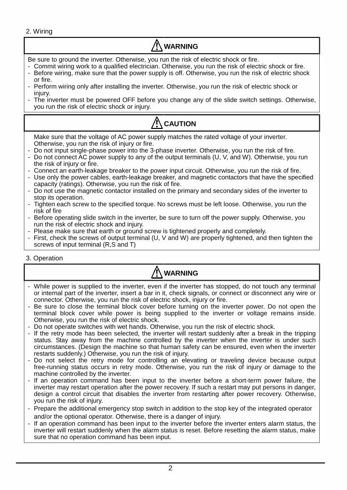
2. Wiring
WARNING
Be sure to ground the inverter. Otherwise, you run the risk of electric shock or fire. - Commit wiring work to a qualified electrician. Otherwise, you run the risk of electric shock or fire. - Before wiring, make sure that the power supply is off. Otherwise, you run the risk of electric shock
or fire. - Perform wiring only after installing the inverter. Otherwise, you run the risk of electric shock or
injury. - The inverter must be powered OFF before you change any of the slide switch settings. Otherwise,
you run the risk of electric shock or injury.
CAUTION
Make sure that the voltage of AC power supply matches the rated voltage of your inverter. Otherwise, you run the risk of injury or fire.
- Do not input single-phase power into the 3-phase inverter. Otherwise, you run the risk of fire. - Do not connect AC power supply to any of the output terminals (U, V, and W). Otherwise, you run
the risk of injury or fire. - Connect an earth-leakage breaker to the power input circuit. Otherwise, you run the risk of fire. - Use only the power cables, earth-leakage breaker, and magnetic contactors that have the specified
capacity (ratings). Otherwise, you run the risk of fire. - Do not use the magnetic contactor installed on the primary and secondary sides of the inverter to
stop its operation. - Tighten each screw to the specified torque. No screws must be left loose. Otherwise, you run the
risk of fire - Before operating slide switch in the inverter, be sure to turn off the power supply. Otherwise, you
run the risk of electric shock and injury. - Please make sure that earth or ground screw is tightened properly and completely. - First, check the screws of output terminal (U, V and W) are properly tightened, and then tighten the
screws of input terminal (R,S and T)
3. Operation
WARNING
- While power is supplied to the inverter, even if the inverter has stopped, do not touch any terminal or internal part of the inverter, insert a bar in it, check signals, or connect or disconnect any wire or connector. Otherwise, you run the risk of electric shock, injury or fire.
- Be sure to close the terminal block cover before turning on the inverter power. Do not open the terminal block cover while power is being supplied to the inverter or voltage remains inside. Otherwise, you run the risk of electric shock.
- Do not operate switches with wet hands. Otherwise, you run the risk of electric shock. - If the retry mode has been selected, the inverter will restart suddenly after a break in the tripping
status. Stay away from the machine controlled by the inverter when the inverter is under such circumstances. (Design the machine so that human safety can be ensured, even when the inverter restarts suddenly.) Otherwise, you run the risk of injury.
- Do not select the retry mode for controlling an elevating or traveling device because output free-running status occurs in retry mode. Otherwise, you run the risk of injury or damage to the machine controlled by the inverter.
- If an operation command has been input to the inverter before a short-term power failure, the inverter may restart operation after the power recovery. If such a restart may put persons in danger, design a control circuit that disables the inverter from restarting after power recovery. Otherwise, you run the risk of injury.
- Prepare the additional emergency stop switch in addition to the stop key of the integrated operator
and/or the optional operator. Otherwise, there is a danger of injury. - If an operation command has been input to the inverter before the inverter enters alarm status, the
inverter will restart suddenly when the alarm status is reset. Before resetting the alarm status, make sure that no operation command has been input.

3
CAUTION
- Do not touch the heat sink, which heats up during the inverter operation. Otherwise, you run the risk of burn injury.
- The inverter allows you to easily control the speed of motor or machine operations. Before operating the inverter, confirm the capacity and ratings of the motor or machine controlled by the inverter. Otherwise, you run the risk of injury.
- Install an external brake system if needed. Otherwise, you run the risk of injury. - When using the inverter to operate a standard motor at a frequency of over 60 Hz, check the
allowable motor speeds with the manufacturers of the motor and the machine to be driven and obtain their consent before starting inverter operation. Otherwise, you run the risk of damage to the motor and machine.
- During inverter operation, check the motor for the direction of rotation, abnormal sound, and vibrations. Otherwise, you run the risk of damage to the machine driven by the motor.
- HIGH VOLTAGE: Dangerous voltage exists even after the Safe Stop is activated. It does NOT mean that the main power has been removed.
4. Maintenance, inspection, and parts replacement
WARNING
- Before inspecting the inverter, be sure to turn off the power supply and wait for 10 minutes or more. Otherwise, you run the risk of electric shock. (Before inspection, confirm that the Charge lamp on the inverter is off.)
- Commit only a designated person to maintenance, inspection, and the replacement of parts. (Be sure to remove wristwatches and metal accessories, e.g., bracelets, before maintenance and inspection work and to use insulated tools for the work.) Otherwise, you run the risk of electric shock and injury.
- Do not rely upon the STO feature to disconnect the power from the motor circuit. It is required isolate the supply before any maintenance is carried out on the motor circuit. See Functional Safety for detail.
5. Others
WARNING
- Never modify the inverter. Otherwise, you run the risk of electric shock and injury.
CAUTION
- Do not discard the inverter with household waste. Contact an industrial waste management company in your area who can treat industrial waste without polluting the environment.
6. When using Safe Stop Function (Certification in progress)
WARNING
- When using Safe Stop function, make sure to check whether the safe stop function properly works when installation (before starting operation). Please carefully refer to Functional Safety for detail.
Contact an industrial waste management company in your area who can treat industrial waste without polluting the environment.

4
UL Cautions, Warnings and Instructions Warnings and Cautions for Troubleshooting and Maintenance
(Standard to comply with : UL508C,CSA C22.2 No.14-05)
Warning Markings
GENERAL:
These devices are open type Power Conversion Equipment. They are intended to be used
in an enclosure. Insulated gate bipolar transistor (IGBT) incorporating microprocessor
technology. They are operated from a single or three-phase source of supply, and intended
to control three-phase induction motors by means of a variable frequency output. The units
are intended for general-purpose industrial applications.
MARKING REQUIREMENTS:
Ratings - Industrial control equipment shall be plainly marked with the Listee’s name,
trademark, File number, or other descriptive marking by which the organization responsible
for the product may be identified;
a) “Maximum surrounding air temperature rating of 50 ºC.”
b) “Solid State motor overload protection reacts with max. 150 % of FLA”.
c) “Install device in pollution degree 2 environment.”
d) “Suitable for use on a circuit capable of delivering not more than 100,000 rms
Symmetrical Amperes, 240 or 480 Volts Maximum.”
e) “When Protected by CC, G, J or R Class fuses.” or “When Protected By A Circuit
Breaker Having An Interrupting Rating Not Less Than 100,000 rms Symmetrical Amperes,
240 or 480 Volts Maximum.”
f) “Integral solid state short circuit protection does not provide branch circuit protection.
Branch circuit protection must be provided in accordance with the National Electrical
Code and any additional local codes.”
g) “Motor over temperature protection is not provided by the drive..”
5
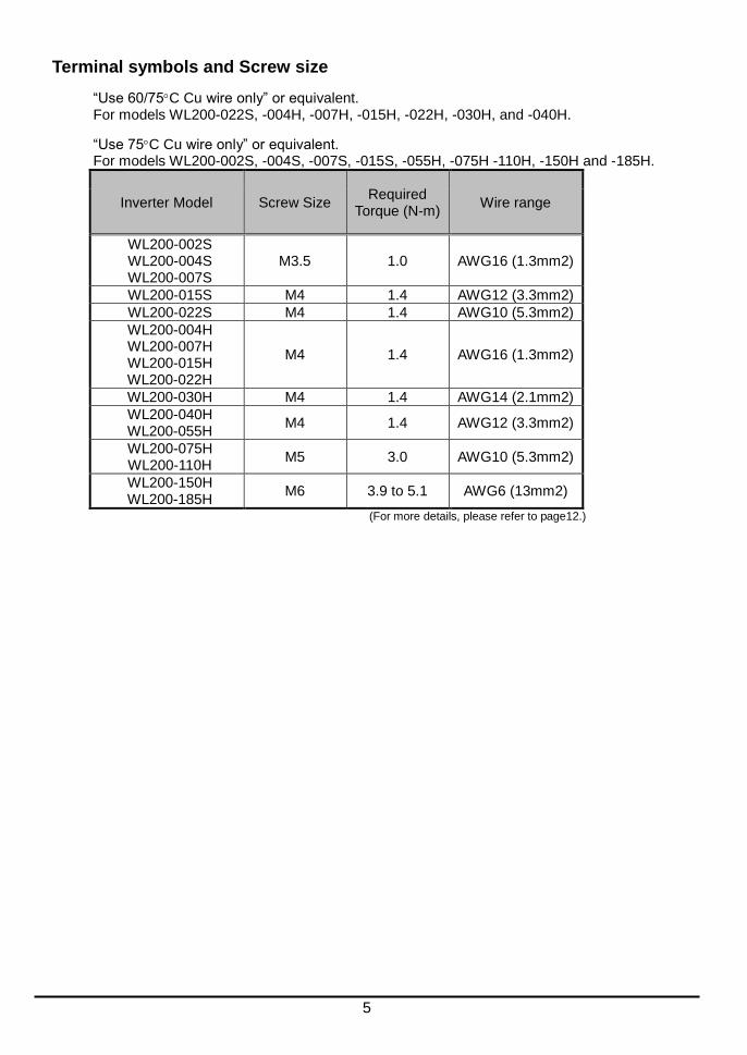
Terminal symbols and Screw size
“Use 60/75C Cu wire only” or equivalent. For models WL200-022S, -004H, -007H, -015H, -022H, -030H, and -040H.
“Use 75C Cu wire only” or equivalent. For models WL200-002S, -004S, -007S, -015S, -055H, -075H -110H, -150H and -185H.
Inverter Model Screw Size Required
Torque (N-m) Wire range
WL200-002S WL200-004S WL200-007S
M3.5 1.0 AWG16 (1.3mm2)
WL200-015S M4 1.4 AWG12 (3.3mm2)
WL200-022S M4 1.4 AWG10 (5.3mm2)
WL200-004H WL200-007H WL200-015H WL200-022H
M4 1.4 AWG16 (1.3mm2)
WL200-030H M4 1.4 AWG14 (2.1mm2)
WL200-040H WL200-055H
M4 1.4 AWG12 (3.3mm2)
WL200-075H WL200-110H
M5 3.0 AWG10 (5.3mm2)
WL200-150H WL200-185H
M6 3.9 to 5.1 AWG6 (13mm2)
(For more details, please refer to page12.)
6
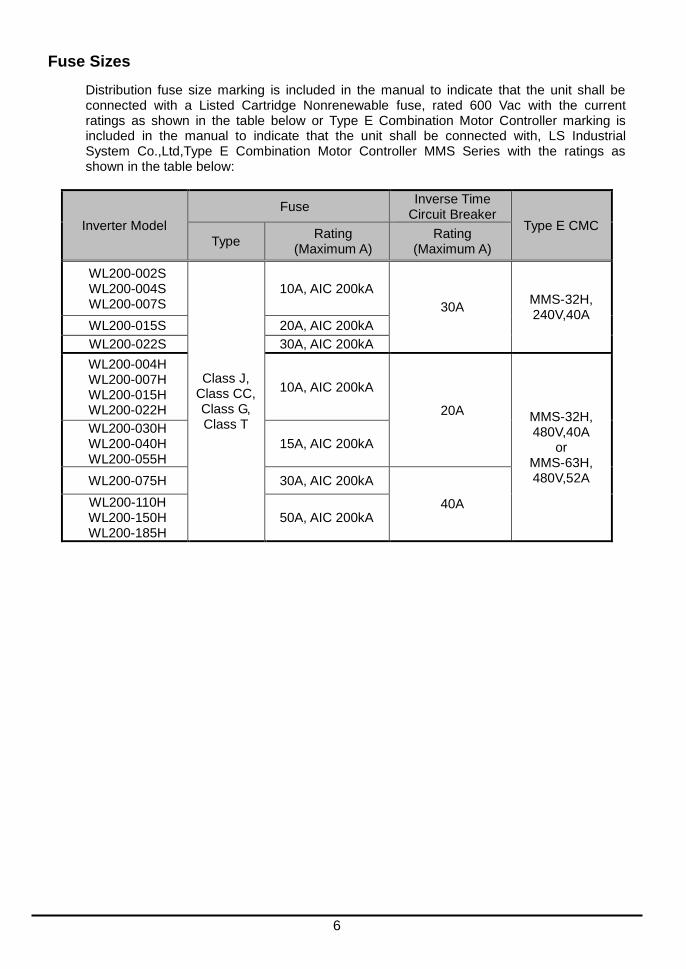
Fuse Sizes
Distribution fuse size marking is included in the manual to indicate that the unit shall be connected with a Listed Cartridge Nonrenewable fuse, rated 600 Vac with the current ratings as shown in the table below or Type E Combination Motor Controller marking is included in the manual to indicate that the unit shall be connected with, LS Industrial System Co.,Ltd,Type E Combination Motor Controller MMS Series with the ratings as shown in the table below:
Inverter Model
Fuse Inverse Time
Circuit Breaker Type E CMC
Type Rating
(Maximum A) Rating
(Maximum A)
WL200-002S WL200-004S WL200-007S
Class J, Class CC, Class G, Class T
10A, AIC 200kA
30A MMS-32H, 240V,40A
WL200-015S 20A, AIC 200kA
WL200-022S 30A, AIC 200kA
WL200-004H WL200-007H WL200-015H WL200-022H
10A, AIC 200kA
20A MMS-32H, 480V,40A
or MMS-63H, 480V,52A
WL200-030H WL200-040H WL200-055H
15A, AIC 200kA
WL200-075H 30A, AIC 200kA
40A WL200-110H WL200-150H WL200-185H
50A, AIC 200kA

7
Inverter Specification Label
The Hitachi WL200 inverters have product labels located on the right side of the housing, as pictured below. Be sure to verify that the specifications on the labels match your power source, and application safety requirements.
Inverter Model Name
The model number for a specific inverter contains useful information about its operating characteristics. Refer to the model number legend below:
Model name
Input ratings
Output ratings
MFG number
WL200 002
S F
Series name Configuration type F=with keypad
Input voltage: S=Single-phase 200V class H=Three-phase 400V class
E
Restricted distribution E=E.U.
Applicable motor capacity in kW 002=0.2kW 040=4.0kW 004=0.4kW 055=5.5kW 007=0.75kW 075=7.5kW 015=1.5kW 110=11kW 022=2.2kW 150=15kW 030=3.0kW 185=18.5kW

8
WL200 Inverter Specifications
Model-specific tables for 200V and 400V class inverters
The following tables are specific to WL200 inverters for the 200V and 400V class model groups.
Item Single-phase 200V class Specifications
WL200 inverters, 200V models 002SFE 004SFE 007SFE 015SFE 022SFE
Applicable motor size
kW 0.2 0.4 0.75 1.5 2.2
HP 1/4 1/2 1 2 3
Rated capacity (kVA)
200V 0.4 1.2 1.5 2.8 4.1
240V 0.5 1.4 1.8 3.4 4.9
Rated input voltage Single-phase: 200V-15% to 240V +10%, 50/60Hz 5%
Rated output voltage Three-phase: 200 to 240V (proportional to input voltage)
Rated output current (A) 1.2 2.6 3.5 6.0 9.6
Braking Without resistor 100%: 50Hz, 50%: 60Hz 70%: 50Hz, 50%: 60Hz
With resistor 150%
DC braking Variable operating frequency, time, and braking force
Weight kg 1.0 1.1 1.1 1.6 1.8
lb 2.2 2.4 2.4 3.1 4.0
Item Three-phase 400V class Specifications
WL200 inverters, 400V models 004HFE 007HFE 015HFE 022HFE 030HFE 040HFE
Applicable motor size
kW 0.4 0.75 1.5 2.2 3.0 4.0
HP 1/2 1 2 3 4 5
Rated capacity (kVA)
380V 1.4 1.4 2.9 3.9 5.4 6.2
480V 1.7 1.8 3.6 5.0 6.8 7.9
Rated input voltage Three-phase: 380V-15% to 480V +10%, 50/60Hz 5%
Rated output voltage Three-phase: 380 to 480V (proportional to input voltage)
Rated output current (A) 1.5 2.1 4.1 5.4 6.9 8.8
Braking Without resistor 100%: 50Hz, 50%: 60Hz 70%: 50Hz,
20%: 60Hz
20%: 50Hz ,
20%: 60Hz
With resistor 150% 100%
DC braking Variable operating frequency, time, and braking force
Weight kg 1.5 1.5 1.6 1.8 1.9 1.9
lb 3.3 3.3 3.5 4.0 4.2 4.2
Item Three-phase 400V class Specifications
WL200 inverters, 400V models 055HFE 075HFE 110HFE 150HFE 185HFE
Applicable motor size
kW 5.5 7.5 11 15 18.5
HP 7.5 10 15 25 25
Rated capacity (kVA)
380V 8.8 13.2 15.8 25.1 29.0
480V 11.1 16.7 20.0 31.6 36.6
Rated input voltage Three-phase: 380V-15% to 480V +10%, 50/60Hz 5%
Rated output voltage Three -phase: 380 to 480V (proportional to input voltage)
Rated output current (A) 11.1 17.5 23.0 31.0 38.0
Braking Without resistor 20%: 50Hz , 20%: 60Hz 20%: 50Hz, 20%: 60Hz
With resistor 100% 80%
DC braking Variable operating frequency, time, and braking force
Weight kg 2.1 3.5 3.5 4.7 5.2
lb 4.6 7.7 7.7 10.4 11.5
NOTE: In Single-phase 200V class and Three-phase 400V class, Inverter types over 2.2kW have some cooling fan.
9
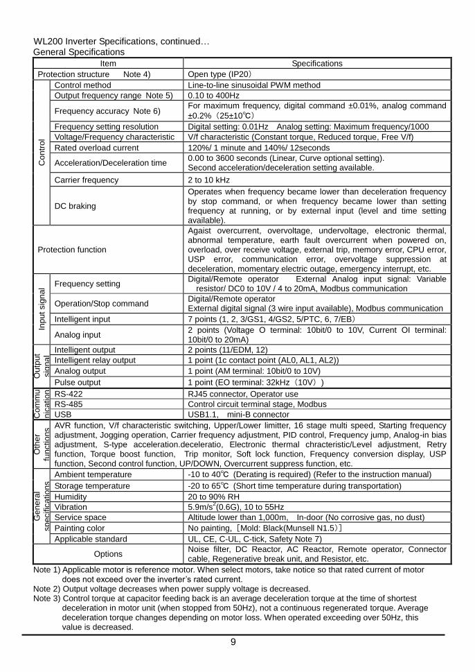
WL200 Inverter Specifications, continued… General Specifications
Item Specifications
Protection structure Note 4) Open type (IP20)
Co
ntr
ol
Control method Line-to-line sinusoidal PWM method
Output frequency range Note 5) 0.10 to 400Hz
Frequency accuracy Note 6) For maximum frequency, digital command ±0.01%, analog command
±0.2%(25±10℃)
Frequency setting resolution Digital setting: 0.01Hz Analog setting: Maximum frequency/1000
Voltage/Frequency characteristic V/f characteristic (Constant torque, Reduced torque, Free V/f)
Rated overload current 120%/ 1 minute and 140%/ 12seconds
Acceleration/Deceleration time 0.00 to 3600 seconds (Linear, Curve optional setting). Second acceleration/deceleration setting available.
Carrier frequency 2 to 10 kHz
DC braking
Operates when frequency became lower than deceleration frequency by stop command, or when frequency became lower than setting frequency at running, or by external input (level and time setting available).
Protection function
Agaist overcurrent, overvoltage, undervoltage, electronic thermal, abnormal temperature, earth fault overcurrent when powered on, overload, over receive voltage, external trip, memory error, CPU error, USP error, communication error, overvoltage suppression at deceleration, momentary electric outage, emergency interrupt, etc.
Inp
ut sig
na
l Frequency setting Digital/Remote operator External Analog input signal: Variable
resistor/ DC0 to 10V / 4 to 20mA, Modbus communication
Operation/Stop command Digital/Remote operator External digital signal (3 wire input available), Modbus communication
Intelligent input 7 points (1, 2, 3/GS1, 4/GS2, 5/PTC, 6, 7/EB)
Analog input 2 points (Voltage O terminal: 10bit/0 to 10V, Current OI terminal: 10bit/0 to 20mA)
Ou
tpu
t
sig
na
l
Intelligent output 2 points (11/EDM, 12)
Intelligent relay output 1 point (1c contact point (AL0, AL1, AL2))
Analog output 1 point (AM terminal: 10bit/0 to 10V)
Pulse output 1 point (EO terminal: 32kHz(10V))
Com
mu
nic
ation
RS-422 RJ45 connector, Operator use
RS-485 Control circuit terminal stage, Modbus
USB USB1.1, mini-B connector
Oth
er
fun
ctio
ns AVR function, V/f characteristic switching, Upper/Lower limitter, 16 stage multi speed, Starting frequency
adjustment, Jogging operation, Carrier frequency adjustment, PID control, Frequency jump, Analog-in bias adjustment, S-type acceleration.deceleratio, Electronic thermal chracteristic/Level adjustment, Retry function, Torque boost function, Trip monitor, Soft lock function, Frequency conversion display, USP function, Second control function, UP/DOWN, Overcurrent suppress function, etc.
Ge
ne
ral
sp
ecific
atio
ns
Ambient temperature -10 to 40℃ (Derating is required) (Refer to the instruction manual)
Storage temperature -20 to 65℃ (Short time temperature during transportation)
Humidity 20 to 90% RH
Vibration 5.9m/s2(0.6G), 10 to 55Hz
Service space Altitude lower than 1,000m, In-door (No corrosive gas, no dust)
Painting color No painting,[Mold: Black(Munsell N1.5)]
Applicable standard UL, CE, C-UL, C-tick, Safety Note 7)
Options Noise filter, DC Reactor, AC Reactor, Remote operator, Connector cable, Regenerative break unit, and Resistor, etc.
Note 1) Applicable motor is reference motor. When select motors, take notice so that rated current of motor does not exceed over the inverter’s rated current.
Note 2) Output voltage decreases when power supply voltage is decreased. Note 3) Control torque at capacitor feeding back is an average deceleration torque at the time of shortest
deceleration in motor unit (when stopped from 50Hz), not a continuous regenerated torque. Average deceleration torque changes depending on motor loss. When operated exceeding over 50Hz, this value is decreased.

10
Note 4) Protection method is compliant with JEM1030. Note 5) When you operate motor exceeding over 50/60Hz, please inquire about an allowable maximum
number of rotations of motor, etc. to motor manufacturer. Note 6) In order to control motors stably, output frequency may exceed over the maximum frequency set by
A004 (A204) by max. 2Hz. Note 7) Functional safety certification is in progress. Note 8) In the case the current tends to increase, for example to trip with overcurrent when torque boost
is activated, please try to operate after initializing with the setting b085=00. Note 9) Parameter setting and EzSQ program cannot be copied between WL200 and WJ200. Note 10) Overcurrent trip level may exceed the level of 200% of nominal current depending on models.
NOTE: In Single-phase 200V class and Three-phase 400V class, Inverter types over 2.2kW have some cooling fan.
The following table shows which models need derating.
1-ph 200V class Need
derating 3-ph 400V class
Need derating
3-ph 400V class Need
derating
WL200-002S - WL200-004H - WL200-040H
WL200-004S - WL200-007H - WL200-055H
WL200-007S WL200-015H WL200-075H -
WL200-015S WL200-022H - WL200-110H
WL200-022S - WL200-030H - WL200-150H
WL200-185H
:need derating -:need no derating
Use the derating curves to help determine the optimal carrier frequency setting for your inverter and
find the output current derating. Be sure to use the proper curve for your particular WL200 inverter
model number. For detail of the derating curves, please refer to Instruction manual.
(Instruction manual can be downloaded from our website.)

11
Basic System Description
A motor control system will obviously include a motor and inverter, as well as a circuit breaker or fuses for safety. If you are connecting a motor to the inverter on a test bench just to get started, that’s all you may need for now. But a system can also have a variety of additional components. Some can be for noise suppression, while others may enhance the inverter’s braking performance. The figure and table below show a system with all the optional components you might need in your final application.
Name Function
Breaker / disconnect
A molded-case circuit breaker (MCCB), ground fault interrupter (GFI), or a fused disconnect device. NOTE: The installer must refer to the NEC and local codes to ensure safety and compliance.
Input-side AC Reactor
This is useful in suppressing harmonics induced on the power supply lines and for improving the power factor. WARNING: Some applications must use an input-side AC
Reactor to prevent inverter damage. Radio noise filter Electrical noise interference may occur on nearby
equipment such as a radio receiver. This magnetic choke filter helps reduce radiated noise (can also be used on output).
EMC filter *1 Reduces the conducted noise on the power supply wiring between the inverter and the power distribution system. Connect to the inverter primary (input) side.
Radio noise filter (use in non-CE applications)
This capacitive filter reduces radiated noise from the main power wires in the inverter input side.
DC link choke Suppress harmonics generated by the inverter. However, it will not protect the input diode bridge rectifier.
Radio noise filter Electrical noise interference may occur on nearby equipment such as a radio receiver. This magnetic choke filter helps reduce radiated noise (can also be used on input).
Output-side AC Reactor
This reactor reduces the vibration in the motor caused by the inverter’s switching waveforms, by smoothing the waveform to approximate commercial power quality. It is also useful to reduce harmonics when wiring from the inverter to the motor is more than 10m in length.
LCR filter Sine wave shaping filter for output side.
Note 1) For CE application, please refer to page 84, “CE-EMC Installation Guidelines”.
Breaker, MCCB or GFI
From power supply
M
Thermal switch
L1 L2 L3
T1 T2 T3
Inverter
+1
+
GND
EMC filter
12
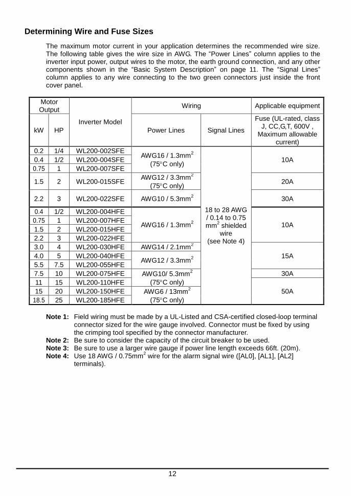
Determining Wire and Fuse Sizes
The maximum motor current in your application determines the recommended wire size. The following table gives the wire size in AWG. The “Power Lines” column applies to the inverter input power, output wires to the motor, the earth ground connection, and any other components shown in the “Basic System Description” on page 11. The “Signal Lines” column applies to any wire connecting to the two green connectors just inside the front cover panel.
Motor Output
Inverter Model
Wiring Applicable equipment
kW HP Power Lines Signal Lines
Fuse (UL-rated, class J, CC,G,T, 600V ,
Maximum allowable current)
0.2 1/4 WL200-002SFE AWG16 / 1.3mm
2
(75C only)
18 to 28 AWG / 0.14 to 0.75 mm
2 shielded wire
(see Note 4)
10A 0.4 1/2 WL200-004SFE
0.75 1 WL200-007SFE
1.5 2 WL200-015SFE AWG12 / 3.3mm
2
(75C only) 20A
2.2 3 WL200-022SFE AWG10 / 5.3mm2 30A
0.4 1/2 WL200-004HFE
AWG16 / 1.3mm2 10A
0.75 1 WL200-007HFE
1.5 2 WL200-015HFE
2.2 3 WL200-022HFE
3.0 4 WL200-030HFE AWG14 / 2.1mm2
15A 4.0 5 WL200-040HFE AWG12 / 3.3mm
2
5.5 7.5 WL200-055HFE
7.5 10 WL200-075HFE AWG10/ 5.3mm2
(75C only)
30A
11 15 WL200-110HFE
50A 15 20 WL200-150HFE AWG6 / 13mm2
(75C only) 18.5 25 WL200-185HFE
Note 1: Field wiring must be made by a UL-Listed and CSA-certified closed-loop terminal
connector sized for the wire gauge involved. Connector must be fixed by using the crimping tool specified by the connector manufacturer.
Note 2: Be sure to consider the capacity of the circuit breaker to be used. Note 3: Be sure to use a larger wire gauge if power line length exceeds 66ft. (20m). Note 4: Use 18 AWG / 0.75mm
2 wire for the alarm signal wire ([AL0], [AL1], [AL2]
terminals).

13
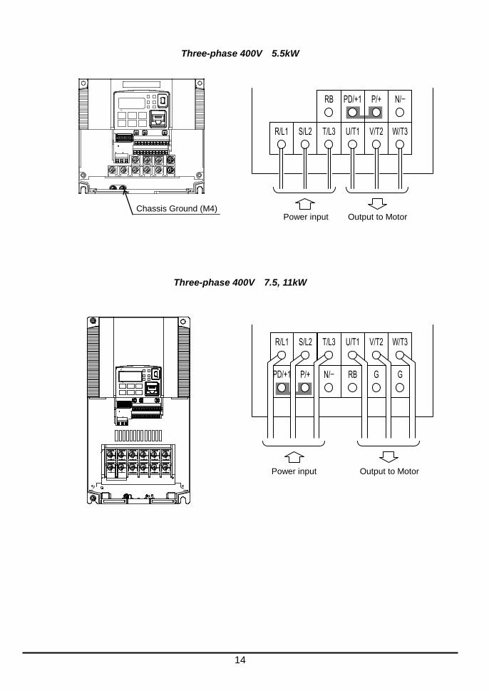
Wire the Inverter Input to a Supply
In this step, you will connect wiring to the input of the inverter. First, you must determine whether the inverter model you have required three-phase power only, or single-phase power only. All models have the same power connection terminals [R/L1], [S/L2], and [T/L3]. So you must refer to the specifications label (on the side of the inverter) for the acceptable power source types! For inverters that can accept single-phase power and are connected that way, terminal [S/L2] will remain unconnected. Note the use of ring lug connectors for a secure connection.
Single-phase 200V 0.2 to 0.75kW
Single-phase 200V 1.5 to 2.2kW Three-phase 400V 0.4 to 4.0kW
Chassis Ground (M4)
Chassis Ground (M4)
L1
Power input Output to Motor
N U/T1 V/T2 W/T3
RB +1 + -
Single-phase Three-phase
R/L1
Power input Output to Motor
S/L2 T/L3 U/T1 V/T2 W/T3
RB PD/+
1
P/+ N/-
L1
Power input Output to Motor
N U/T1 V/T2 W/T3
RB +1 + -
Single-phase
14
Three-phase 400V 5.5kW
Three-phase 400V 7.5, 11kW
W/T3 V/T2 U/T1 T/L3 S/L2 R/L1
N/- P/+ PD/+1 RB
Power input Output to Motor Chassis Ground (M4)
G G RB N/- P/+ PD/+1
W/T3 V/T2 U/T1 T/L3 S/L2 R/L1
Power input Output to Motor
15
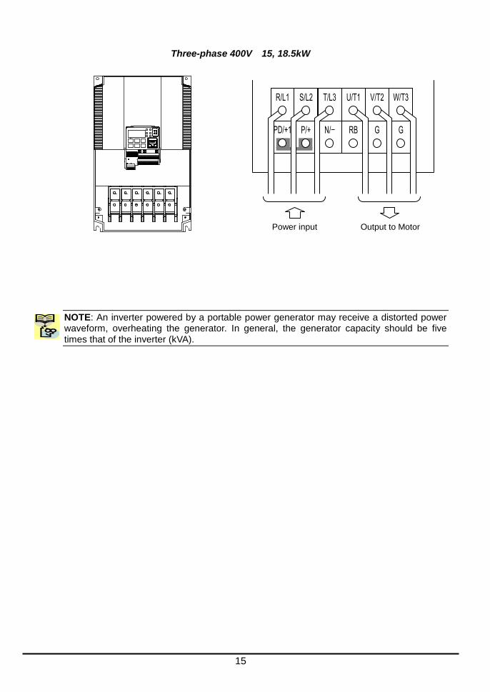
Three-phase 400V 15, 18.5kW
NOTE: An inverter powered by a portable power generator may receive a distorted power waveform, overheating the generator. In general, the generator capacity should be five times that of the inverter (kVA).
G G RB N/- P/+ PD/+1
W/T3 V/T2 U/T1 T/L3 S/L2 R/L1
Power input Output to Motor

16
Using the Front Panel Keypad
Please take a moment to familiarize yourself with the keypad layout shown in the figure below. The display is used in programming the inverter’s parameters, as well as monitoring specific parameter values during operation.
Key and Indicator Legend Items Contents
(1) POWER LED Turns ON (Green) while the inverter is powered up.
(2) ALARM LED Turns ON (Red) when the inverter trips.
(3) Program LED Turns ON (Green) when the display shows changeable parameter. Blinks when there is a mismatch in setting.
(4) RUN LED Turns ON (Green) when the inverter is driving the motor.
(5) Monitor LED [Hz] Turns ON (Green) when the displayed data is frequency related.
(6) Monitor LED [A] Turns ON (Green) when the displayed data is current related.
(7) Run command LED Turns ON (Green) when a Run command is set to the operator. (Run key is effective.)
(8) 7-seg LED Shows each parameter, monitors etc.
(9) RUN key Makes inverter run.
(10) STOP/RESET key Makes inverter decelerates to a stop. Reset the inverter when it is in trip situation
(11) ESC key
Go to the top of next function group, when a function mode is shown Cancel the setting and return to the function code, when a data is shown Moves the cursor to a digit left, when it is in digit-to-digit setting mode
Pressing for 1 second leads to display data of , regardless of current display.
(12) Up key (13) Down key
Increase or decrease the data. Pressing the both keys at the same time gives you the digit-to-digit edit.
(14) SET key Go to the data display mode when a function code is shown Stores the data and go back to show the function code, when data is shown. Moves the cursor to a digit right, when it is in digit-to-digit display mode
(15) USB connector Connect USB connector (mini-B) for using PC communication
(16) RJ45 connector Connect RJ45 jack for remote operator
(17)Remote Operator Keys on the front panel don’t work while the remote operator is connected ([STOP] can be
validated). What to display on the 7-seg can be set with parameter
1
2
RUN
ESC
STOP
RESET
SET
(1) POWER LED
(2) ALARM LED
(8) 7-seg LED
(4) RUN LED
(10) STOP/RESET key
(15) USB connector
(3) Program LED
(16) RJ45 connector
(14) SET key
(13) Down key (12) Up key
(11) ESC key
(9) RUN key
(7) Run command LED
(5) Monitor LED [Hz]
(6) Monitor LED [A]
RUN PWR
Hz ALM
A PLG
17
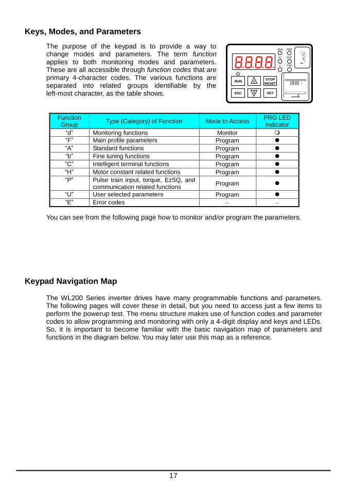
Keys, Modes, and Parameters
The purpose of the keypad is to provide a way to change modes and parameters. The term function applies to both monitoring modes and parameters. These are all accessible through function codes that are primary 4-character codes. The various functions are separated into related groups identifiable by the left-most character, as the table shows.
Function Group
Type (Category) of Function Mode to Access PRG LED Indicator
“d” Monitoring functions Monitor
“F” Main profile parameters Program “A” Standard functions Program “b” Fine tuning functions Program “C” Intelligent terminal functions Program “H” Motor constant related functions Program “P” Pulse train input, torque, EzSQ, and
communication related functions Program
“U” User selected parameters Program “E” Error codes
You can see from the following page how to monitor and/or program the parameters.
Keypad Navigation Map
The WL200 Series inverter drives have many programmable functions and parameters. The following pages will cover these in detail, but you need to access just a few items to perform the powerup test. The menu structure makes use of function codes and parameter codes to allow programming and monitoring with only a 4-digit display and keys and LEDs. So, it is important to become familiar with the basic navigation map of parameters and functions in the diagram below. You may later use this map as a reference.
RUN
RUN
ESC SET
STOP
RESET 1
2
PWR
Hz ALM
PGM A

18
NOTE: Pressing the [ESC] key will make the display go to the top of next function group,
regardless the display contents. (e.g. [ESC] )
Press the both up and down key at the same
time in func. code or data display, then
single-digit edit mode will be enabled.
ESC
SET
Group "d"
Func. code display
.
Group "F"
Func. code display
.
.
SET
SET ESC
SET ESC
Save
Group "A"
Func. code display
SET
SET ESC
SET ESC
Data display
When data is changed, the display
starts blinking, which means that
new data has not been activated yet.
: Saves the data in EEPROM and
returns to func. code display.
: Cancels the data change and
returns to func. code display.
SET
ESC
Group "b"
ESC
Func. code display
: Jumps to the next group ESC
Func. code display
: Moves to data display SET
ESC
ESC
Data display (F001 to F003)
Data does not blink because of real time synchronizing
: Saves the data in EEPROM
and returns to func. code display.
: Returns to func. code display without saving data.
SET
ESC

19
[Setting example]
After power ON, changing from . display to change the (Run command source)
data.
Function code xxx are for monitor and not possible to change.
Function codes xxx other than are reflected on the performance just after changing the data
(before pressing SET key), and there will be no blinking.
Display is solid lighting.
.
Data of will be shown on the display after the first power ON
Press [ESC] key to show the function code
Press [ESC] key to move on to the function group
Press [ESC] key Once to move on to the function group .
Press Up key to change increase function code ( )
Press SET key to display the data of
Press SET key to set and save the data
When data is changed, the display starts blinking, which means that new data has not been activated yet.
ESC
SET ESC
ESC
SET
ESC
:Fixes and stores the data and moves back to the function code :Cancels the change and moves back to the function code
SET
ESC
SET
Press up key to increase the data ( )

20
When a function code is shown… When a data is shown…
ESC key Move on to the next function group Cancels the change and moves back to the function code
SET key Move on to the data display Fix and stores the data and moves back to the function code
key Increase function code Increase data value
key Decrease function code Decrease data value
Note
Keep pressing [ESC] key for more than 1 second leads to d001 display, regardless the display situation. But
note that the display will circulates while keep pressing the [ESC] key because of the original function of the
key.
(e.g. … displays . after 1 second)
21
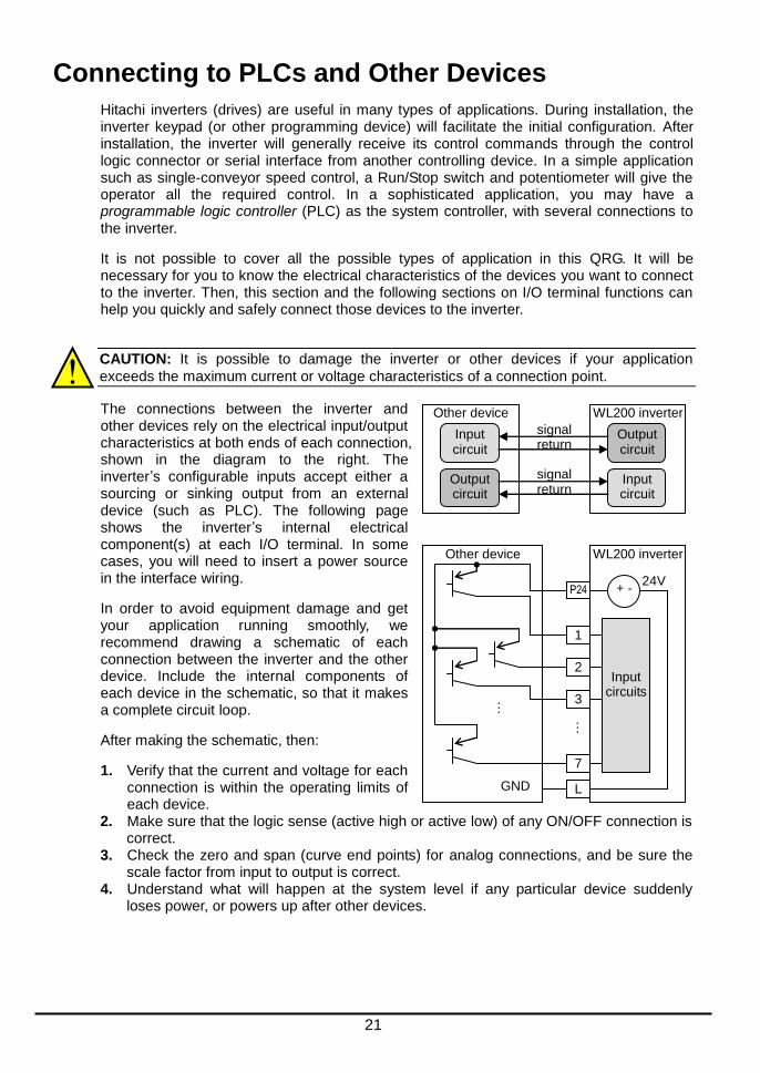
Connecting to PLCs and Other Devices
Hitachi inverters (drives) are useful in many types of applications. During installation, the inverter keypad (or other programming device) will facilitate the initial configuration. After installation, the inverter will generally receive its control commands through the control logic connector or serial interface from another controlling device. In a simple application such as single-conveyor speed control, a Run/Stop switch and potentiometer will give the operator all the required control. In a sophisticated application, you may have a programmable logic controller (PLC) as the system controller, with several connections to the inverter.
It is not possible to cover all the possible types of application in this QRG. It will be necessary for you to know the electrical characteristics of the devices you want to connect to the inverter. Then, this section and the following sections on I/O terminal functions can help you quickly and safely connect those devices to the inverter.
CAUTION: It is possible to damage the inverter or other devices if your application
exceeds the maximum current or voltage characteristics of a connection point.
The connections between the inverter and other devices rely on the electrical input/output characteristics at both ends of each connection, shown in the diagram to the right. The inverter’s configurable inputs accept either a sourcing or sinking output from an external device (such as PLC). The following page shows the inverter’s internal electrical component(s) at each I/O terminal. In some cases, you will need to insert a power source in the interface wiring.
In order to avoid equipment damage and get your application running smoothly, we recommend drawing a schematic of each connection between the inverter and the other device. Include the internal components of each device in the schematic, so that it makes a complete circuit loop.
After making the schematic, then:
1. Verify that the current and voltage for each connection is within the operating limits of each device.
2. Make sure that the logic sense (active high or active low) of any ON/OFF connection is correct.
3. Check the zero and span (curve end points) for analog connections, and be sure the scale factor from input to output is correct.
4. Understand what will happen at the system level if any particular device suddenly loses power, or powers up after other devices.
Other device
Input circuit
Output circuit
WL200 inverter
Input circuit
Output circuit
signal return
signal return
Other device WL200 inverter
Input circuits
P24
1
2
3
7
L
24V + -
GND
…
…
22
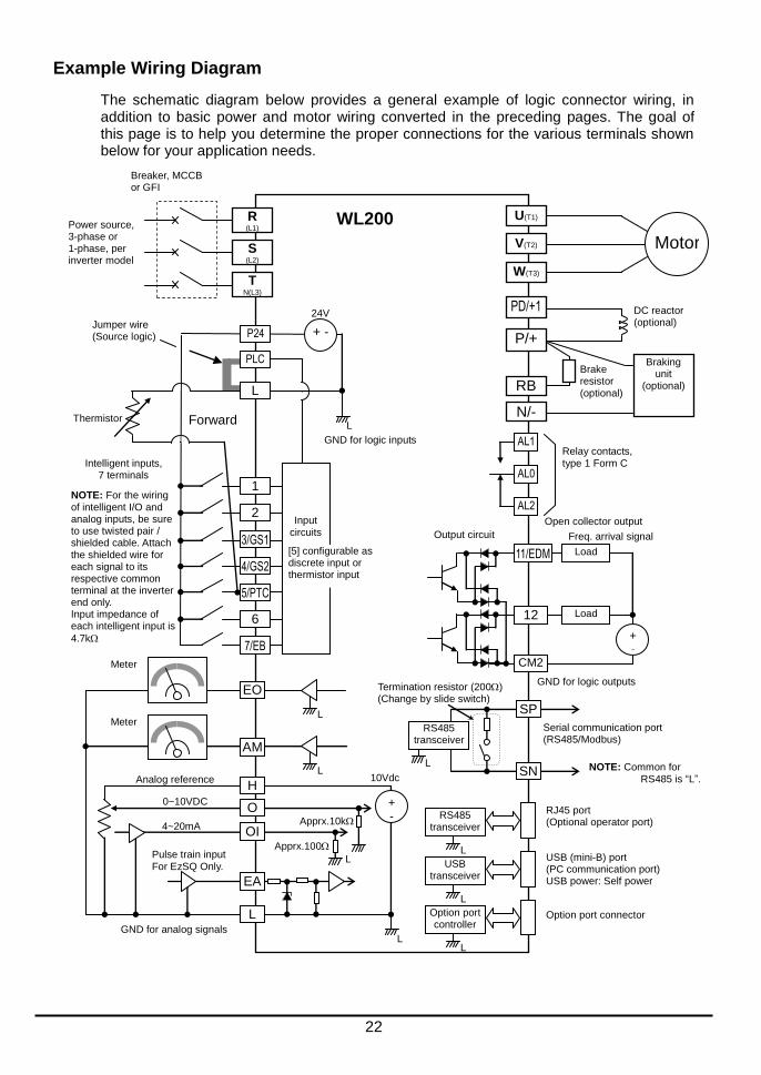
Example Wiring Diagram
The schematic diagram below provides a general example of logic connector wiring, in addition to basic power and motor wiring converted in the preceding pages. The goal of this page is to help you determine the proper connections for the various terminals shown below for your application needs.
Breaker, MCCB or GFI
Power source, 3-phase or 1-phase, per inverter model
AM
Meter
H
L
Analog reference
0~10VDC
4~20mA
GND for analog signals
WL200
Motor
PD/+1
P/+
R (L1)
S (L2)
T N(L3)
U(T1)
V(T2)
W(T3)
N/-
DC reactor (optional)
AL1
AL0
AL2
Relay contacts, type 1 Form C
EO
Meter
Pulse train input For EzSQ Only.
RB
Brake resistor (optional)
11/EDM Load
Freq. arrival signal
Open collector output
Output circuit
GND for logic outputs
12 Load
+ -
CM2
L
+ -
O
OI
EA
Apprx.10k
10Vdc
Apprx.100
RS485 transceiver
RJ45 port (Optional operator port)
USB transceiver
USB (mini-B) port (PC communication port) USB power: Self power
L
L
Option port controller
Option port connector
L
L
L
L L
SP
SN
RS485 transceiver
Termination resistor (200) (Change by slide switch)
Serial communication port (RS485/Modbus)
Forward Thermistor
Intelligent inputs, 7 terminals
GND for logic inputs
NOTE: For the wiring of intelligent I/O and analog inputs, be sure to use twisted pair / shielded cable. Attach the shielded wire for each signal to its respective common terminal at the inverter end only. Input impedance of each intelligent input is
4.7k
Jumper wire (Source logic)
NOTE: Common for RS485 is “L”.
Braking unit
(optional)
24V
P24 + -
1
2
3/GS1
4/GS2
5/PTC
6
7/EB
L
PLC
L
Input circuits
[5] configurable as discrete input or thermistor input
23
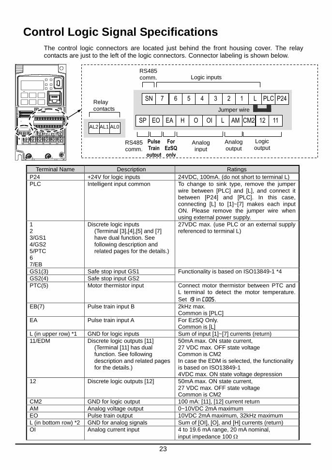
Control Logic Signal Specifications
The control logic connectors are located just behind the front housing cover. The relay contacts are just to the left of the logic connectors. Connector labeling is shown below.
Terminal Name Description Ratings
P24 +24V for logic inputs 24VDC, 100mA. (do not short to terminal L)
PLC Intelligent input common To change to sink type, remove the jumper wire between [PLC] and [L], and connect it between [P24] and [PLC]. In this case, connecting [L] to [1]~[7] makes each input ON. Please remove the jumper wire when using external power supply.
1 2 3/GS1 4/GS2 5/PTC 6 7/EB
Discrete logic inputs (Terminal [3],[4],[5] and [7] have dual function. See following description and related pages for the details.)
27VDC max. (use PLC or an external supply referenced to terminal L)
GS1(3) Safe stop input GS1 Functionality is based on ISO13849-1 *4
GS2(4) Safe stop input GS2
PTC(5) Motor thermistor input Connect motor thermistor between PTC and L terminal to detect the motor temperature.
Set in .
EB(7) Pulse train input B 2kHz max. Common is [PLC]
EA Pulse train input A For EzSQ Only. Common is [L]
L (in upper row) *1 GND for logic inputs Sum of input [1]~[7] currents (return)
11/EDM Discrete logic outputs [11] (Terminal [11] has dual function. See following description and related pages for the details.)
50mA max. ON state current, 27 VDC max. OFF state voltage Common is CM2 In case the EDM is selected, the functionality is based on ISO13849-1 4VDC max. ON state voltage depression
12 Discrete logic outputs [12] 50mA max. ON state current, 27 VDC max. OFF state voltage Common is CM2
CM2 GND for logic output 100 mA: [11], [12] current return
AM Analog voltage output 0~10VDC 2mA maximum
EO Pulse train output 10VDC 2mA maximum, 32kHz maximum
L (in bottom row) *2 GND for analog signals Sum of [OI], [O], and [H] currents (return)
OI Analog current input 4 to 19.6 mA range, 20 mA nominal,
input impedance 100
Analog output
Logic inputs
Logic output
Jumper wire
PLC
Analog input
For EzSQ only
Pulse Train
output
RS485 comm.
RS485 comm.
P24 1 L 3 2 5 4 6 SN 7
12 11 AM CM2 OI L H O EA SP EO AL2 AL1 AL0
Relay contacts

24
Terminal Name Description Ratings
O Analog voltage input 0 to 9.8 VDC range, 10 VDC nominal,
input impedance 10 k
H +10V analog reference 10VDC nominal, 10mA max.
SP, SN Serial communication terminal For RS485 Modbus communication.
AL0, AL1, AL2 *3 Relay common contact 250VAC, 2.5A (R load) max. 250VAC, 0.2A (I load, P.F.=0.4) max. 100VAC, 10mA min. 30VDC, 3.0A (R load) max. 30VDC, 0.7A (I load, P.F.=0.4) max. 5VDC, 100mA min.
Note 1: The two terminals [L] are electrically connected together inside the inverter. Note 2: We recommend using [L] logic GND (to the right) for logic input circuits and [L]
analog GND (to the left) for analog I/O circuits. Note 3: Refer to page 41 for details of trip signals. Note 4: Refer to page 88, “Functional Safety” for details
Wiring sample of control logic terminal (Source logic)
Note: If relay is connected to intelligent output, install a diode across the relay coil
(reverse-biased) in order to suppress the turn-off spike.
Caution for intelligent terminals setting
Please avoid conducting below procedure, because if you follow procedure describe below, the inverter setting will be initialized.
1) Turning on power while [Intelligent input terminal 1/2/3 are ON] and [Intelligent input terminal 4/5/6/7 are OFF].
2) After 1)’s condition, turning off power.
3) After 2)'s condition, turning on power while [Intelligent input terminal 2/3/4 are ON] and [Intelligent input terminal 1/5/6/7 are OFF].
SP EO EA H O OI L AM CM2 12 11/EDM
Freq. meter
Variable resistor for freq. setting
(1k-2k)
Jumper wire (source logic)
RY
SN 7/EB 6 5/PTC 4/GS2 3/GS1 2 1 L PLC P24
RY

25
Sink/source logic of intelligent input terminals
Source or sink logic is switched by a jumper wire as below.
Wire size for control and relay terminals
Use wires within the specifications listed below. For safe wiring and reliability, it is recommended to use ferrules, but if solid or stranded wire is used, stripping length should be 8mm.
Solid mm
2 (AWG)
Stranded mm
2 (AWG)
Ferrule mm
2 (AWG)
Control logic terminal
0.2 to 1.5 (AWG 24 to 16)
0.2 to 1.0 (AWG 24 to 17)
0.25 to 0.75 (AWG 24 to 18)
Relay terminal 0.2 to 1.5
(AWG 24 to 16) 0.2 to 1.0
(AWG 24 to 17) 0.25 to 0.75
(AWG 24 to 18)
Control logic terminal
Relay output terminal
8mm
Jumper wire
PLC P24 L 1 2
Sink logic
Jumper wire
PLC P24 L 1 2
Source logic

26
Recommended ferrule
For safe wiring and reliability, it is recommended to use following ferrules. When you use an option mounted, please use a rod terminal without sleeve to wire so that to avoid hitting the option case. Rod terminal with sleeve
Wire size mm
2 (AWG)
Model name of ferrule *
L1 [mm]
L2 [mm]
Φd [mm]
ΦD [mm]
0.25 (24) AI 0.25-8YE 8 12.5 0.8 2.0
0.34 (22) AI 0.34-8TQ 8 12.5 0.8 2.0
0.5 (20) AI 0.5-8WH 8 14 1.1 2.5
0.75 (18) AI 0.75-8GY 8 14 1.3 2.8
Rod terminal without sleeve
Wire size mm
2 (AWG)
Model name of ferrule *
L1 [mm]
L2 [mm]
Φd [mm]
ΦD [mm]
0.5 (20) A 0,5 – 8 7.3 8 1.0 2.1
0.75 (18) A 0,75- 8 7.3 8 1.2 2.3
* Supplier: Phoenix contact
Crimping pliers: CRIMPFOX UD 6-4 or CRIMPFOX ZA 3
How to connect? (1) Push down an orange actuating lever by a slotted screwdriver (width 2.5mm max.). (2) Plug in the conductor. (3) Pull out the screwdriver then the conductor is fixed.
Push down an
orange actuating
lever.
2.5mm
Plug in the
conductor.
Pull out the
screwdriver to fix
the conductor.

27
Intelligent Terminal Listing Intelligent Inputs
The following table shows the list of the functions which can be assigned to each intelligent input. Please refer to the Instruction manual for the detail information.
Input Function Summary Table
Symbol Code Function Name
FW 00 Forward Run/Stop
RV 01 Reverse Run/Stop
CF1 02 Multi-speed Select, Bit 0 (LSB)
CF2 03 Multi-speed Select, Bit 1
CF3 04 Multi-speed Select, Bit 2
CF4 05 Multi-speed Select, Bit 3 (MSB)
JG 06 Jogging
DB 07 External DC braking
SET 08 Set (select) 2nd Motor Data
2CH 09 2-stage Acceleration and Deceleration
FRS 11 Free-run Stop
EXT 12 External Trip
USP 13 Unattended Start Protection
CS 14 Commercial power source switchover
SFT 15 Software Lock
AT 16 Analog Input Voltage/Current Select
RS 18 Reset Inverter
PTC 19 PTC thermistor Thermal Protection
STA 20 Start (3-wire interface)
STP 21 Stop (3-wire interface)
F/R 22 FWD, REV (3-wire interface)
PID 23 PID Disable
PIDC 24 PID Reset
UP 27 Remote Control UP Function
DWN 28 Remote Control Down Function
UDC 29 Remote Control Data Clearing
OPE 31 Operator Control
SF1~SF7 32~38 Multi-speed Select, Bit operation Bit 1~7
OLR 39 Overload Restriction Source Changeover
BOK 44 Brake confirmation
LAC 46 LAD cancellation
ADD 50 ADD frequency enable
F-TM 51 Force Terminal Mode
KHC 53 Clear watt-hour data
MI1~MI7 56~62 General purpose input (1)~(7)
AHD 65 Analog command hold
GS1 77 STO1 input (Safety related signal)
GS2 78 STO2 input (Safety related signal)
485 81 Starting communication signal
PRG 82 Executing EzSQ program
HLD 83 Retain output frequency
ROK 84 Permission of Run command
DISP 86 Display limitation
NO 255 No assign
28
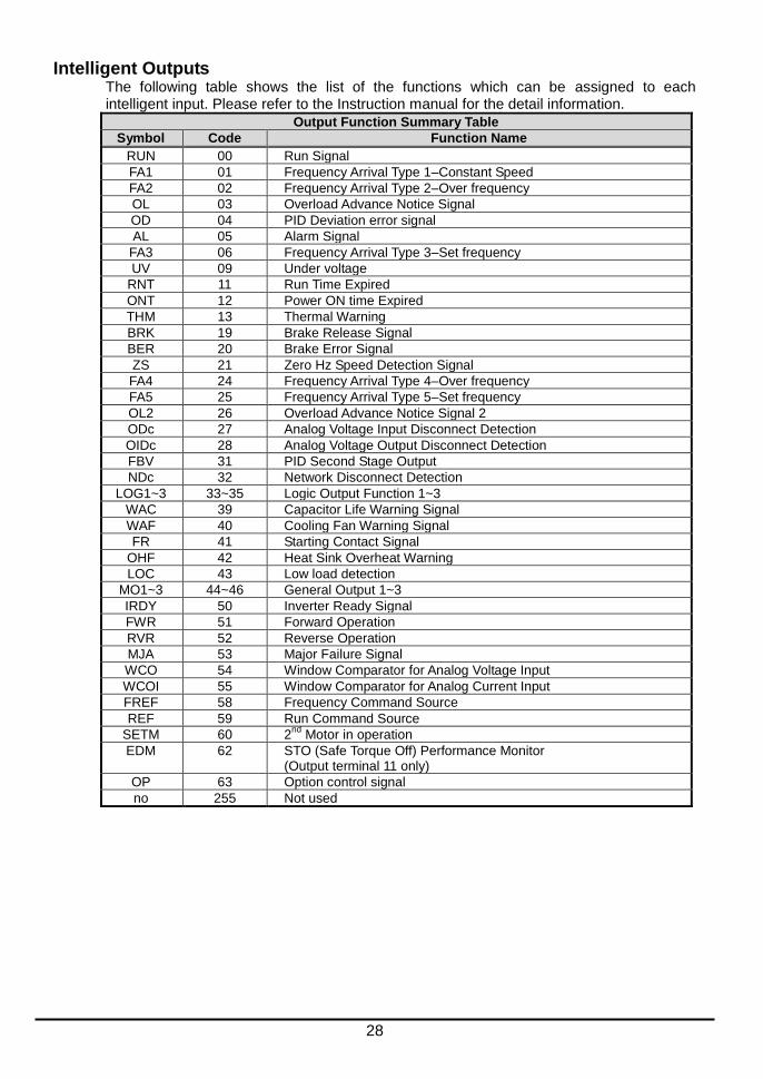
Intelligent Outputs
The following table shows the list of the functions which can be assigned to each intelligent input. Please refer to the Instruction manual for the detail information.
Output Function Summary Table
Symbol Code Function Name
RUN 00 Run Signal
FA1 01 Frequency Arrival Type 1–Constant Speed
FA2 02 Frequency Arrival Type 2–Over frequency
OL 03 Overload Advance Notice Signal
OD 04 PID Deviation error signal
AL 05 Alarm Signal
FA3 06 Frequency Arrival Type 3–Set frequency
UV 09 Under voltage
RNT 11 Run Time Expired
ONT 12 Power ON time Expired
THM 13 Thermal Warning
BRK 19 Brake Release Signal
BER 20 Brake Error Signal
ZS 21 Zero Hz Speed Detection Signal
FA4 24 Frequency Arrival Type 4–Over frequency
FA5 25 Frequency Arrival Type 5–Set frequency
OL2 26 Overload Advance Notice Signal 2
ODc 27 Analog Voltage Input Disconnect Detection
OIDc 28 Analog Voltage Output Disconnect Detection
FBV 31 PID Second Stage Output
NDc 32 Network Disconnect Detection
LOG1~3 33~35 Logic Output Function 1~3
WAC 39 Capacitor Life Warning Signal
WAF 40 Cooling Fan Warning Signal
FR 41 Starting Contact Signal
OHF 42 Heat Sink Overheat Warning
LOC 43 Low load detection
MO1~3 44~46 General Output 1~3
IRDY 50 Inverter Ready Signal
FWR 51 Forward Operation
RVR 52 Reverse Operation
MJA 53 Major Failure Signal
WCO 54 Window Comparator for Analog Voltage Input
WCOI 55 Window Comparator for Analog Current Input
FREF 58 Frequency Command Source
REF 59 Run Command Source
SETM 60 2nd
Motor in operation
EDM 62 STO (Safe Torque Off) Performance Monitor (Output terminal 11 only)
OP 63 Option control signal
no 255 Not used
29
Using Intelligent Input Terminals
Terminals [1], [2], [3], [4], [5], [6] and [7] are identical, programmable inputs for general use. The input circuits can use the inverter’s internal (isolated) +24V field supply or an external power supply. This section describes input circuits operation and how to connect them properly to switches or transistor outputs on field devices.
The WL200 inverter features selectable sinking or sourcing inputs. These terms refer to the connection to the external switching device–it either sinks current (from the input to GND) or sources current (from a power source) into the input. Note that the sink/source naming convention may be different in your particular country or industry. In any case, just follow the wiring diagrams in this section for your application.
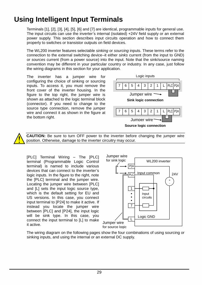
The inverter has a jumper wire for configuring the choice of sinking or sourcing inputs. To access it, you must remove the front cover of the inverter housing. In the figure to the top right, the jumper wire is shown as attached to the logic terminal block (connector). If you need to change to the source type connection, remove the jumper wire and connect it as shown in the figure at the bottom right.
CAUTION: Be sure to turn OFF power to the inverter before changing the jumper wire position. Otherwise, damage to the inverter circuitry may occur.
[PLC] Terminal Wiring – The [PLC] terminal (Programmable Logic Control terminal) is named to include various devices that can connect to the inverter’s logic inputs. In the figure to the right, note the [PLC] terminal and the jumper wire. Locating the jumper wire between [PLC] and [L] sets the input logic source type, which is the default setting for EU and US versions. In this case, you connect input terminal to [P24] to make it active. If instead you locate the jumper wire between [PLC] and [P24], the input logic will be sink type. In this case, you connect the input terminal to [L] to make it active.
The wiring diagram on the following pages show the four combinations of using sourcing or sinking inputs, and using the internal or an external DC supply.
WL200 inverter
P24
1
7
L
24V PLC
Input circuits
+ -
Logic GND
Input common
Jumper wire
for sink logic
Jumper wire
for source logic
Logic inputs
5 4 3 2 1 L PLC P24
Source logic connection
Jumper wire
7 6
5 4 3 2 1 L PLC P24
Sink logic connection
Jumper wire
7 6

30
The two diagrams below input wiring circuits using the inverter ’s internal +24V supply. Each diagram shows the connection for simple switches, or for a field device with transistor outputs. Note that in the lower diagram, it is necessary to connect terminal [L] only when using the field device with transistors. Be sure to use the correct connection of the jumper wire shown for each wiring diagram.
Sinking Inputs, Internal Supply
Jumper wire = [PLC] – [P24] position
GND
7
1
Field device
Open collector outputs, NPN transistors
WL200
P24
1
7
24V
PLC
Input circuits
+ -
Logic GND
Input common
Jumper wire
Input switches
L
Sourcing Inputs, Internal Supply
Jumper wire = [PLC] – [L] position
Common to [P24]
7
1
Field device
PNP transistor sourcing outputs
WL200
P24
1
7
24V
PLC
Input circuits
+ -
Logic GND
Input common
Jumper wire
Input switches
L
GND to PNP bias circuits

31
The two diagrams below show input wiring circuits using an external supply. If using the “Sinking Inputs, External Supply” in below wiring diagram, be sure to remove the jumper wire, and use a diode (*) with the external supply. This will prevent a power supply contention in case the jumper wire is accidentally placed in the incorrect position. For the “Sourcing Inputs, External Supply”, please connect the jumper wire as drawn in the diagram below.
Sinking Inputs, External Supply
Jumper wire = Removed
GND
7
1
Field device
Open collector outputs, NPN transistors
WL200
P24
1
7
24V
PLC
Input circuits
+ -
Logic GND
Input common
Input switches
L
24V
+ -
+ -
24V
*
* Note: Make sure to remove the jumper wire in case of using
an external power supply.
Sourcing Inputs, External Supply
Jumper wire = Removed
7
1
Field device
WL200
P24
1
7
24V
PLC
Input circuits
+ -
Input common
Input switches
L
GND
PNP transistor sourcing outputs
24V + -
24V
+ -

32
CAUTION: Be sure to connect diode in between "P24" and "PLC" when connecting plural inverters with digital input wiring in common.
By having ability inverter doesn’t block the current flowing into itself when it is not powered. This may cause the closed circuit when two or more inverters are connected to common I/O wiring as shown below to result in unexpected turning the on the input. To avoid this closed circuit, please put the diode (rated:50V/0.1A) in the path as described below.
Jumper wire
Inserting diode
P24
PLC
L
1
P24
PLC
L
1
Switch OFF
Power ON
Power OFF
Input ON
P24
PLC
L
1
P24
PLC
L
1
Switch OFF
Power ON
Power OFF
Input OFF
Jumper wire
1
Switch OFF
Switch OFF
Input OFF
Input ON
P24
PLC
L
P24
PLC
L
P24
PLC
L
P24
PLC
L
1
1 1
Jumper wire
In case of Source logic
Jumper wire
33
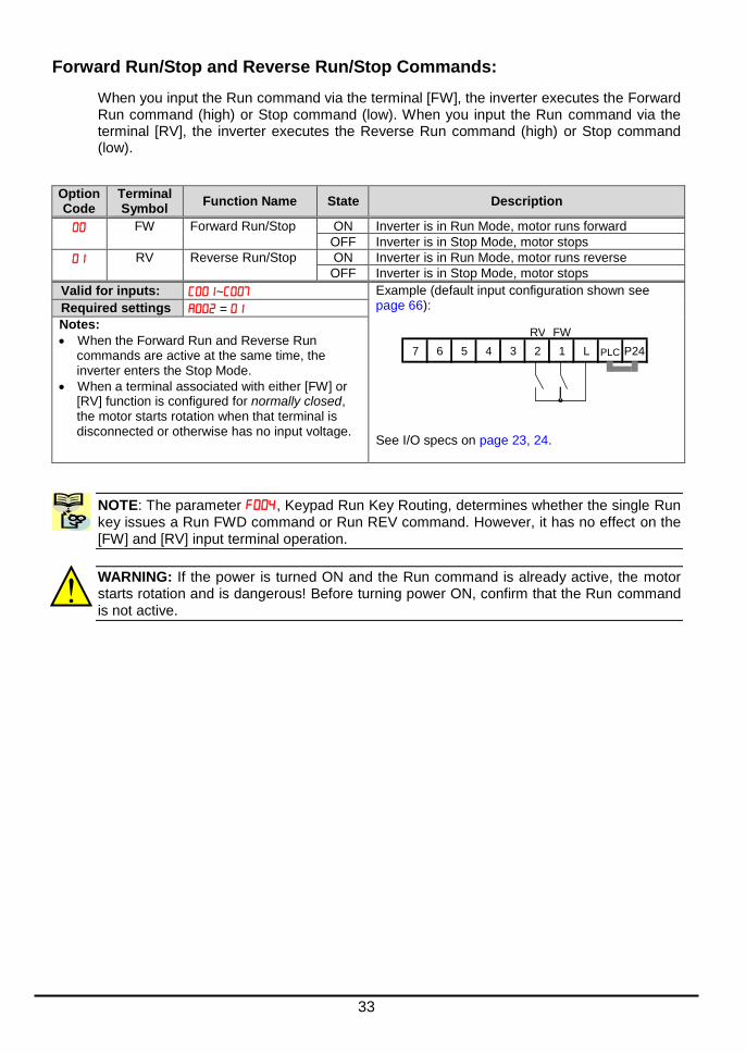
Forward Run/Stop and Reverse Run/Stop Commands:
When you input the Run command via the terminal [FW], the inverter executes the Forward Run command (high) or Stop command (low). When you input the Run command via the terminal [RV], the inverter executes the Reverse Run command (high) or Stop command (low).
Option Code
Terminal Symbol
Function Name State Description
FW Forward Run/Stop ON Inverter is in Run Mode, motor runs forward
OFF Inverter is in Stop Mode, motor stops
RV Reverse Run/Stop ON Inverter is in Run Mode, motor runs reverse
OFF Inverter is in Stop Mode, motor stops
Valid for inputs: ~ Example (default input configuration shown see page 66): See I/O specs on page 23, 24.
Required settings =
Notes:
When the Forward Run and Reverse Run commands are active at the same time, the inverter enters the Stop Mode.
When a terminal associated with either [FW] or [RV] function is configured for normally closed, the motor starts rotation when that terminal is disconnected or otherwise has no input voltage.
NOTE: The parameter , Keypad Run Key Routing, determines whether the single Run key issues a Run FWD command or Run REV command. However, it has no effect on the [FW] and [RV] input terminal operation.
WARNING: If the power is turned ON and the Run command is already active, the motor starts rotation and is dangerous! Before turning power ON, confirm that the Run command is not active.
RV FW
7 6 5 4 3 2 1 L P24 PLC
34
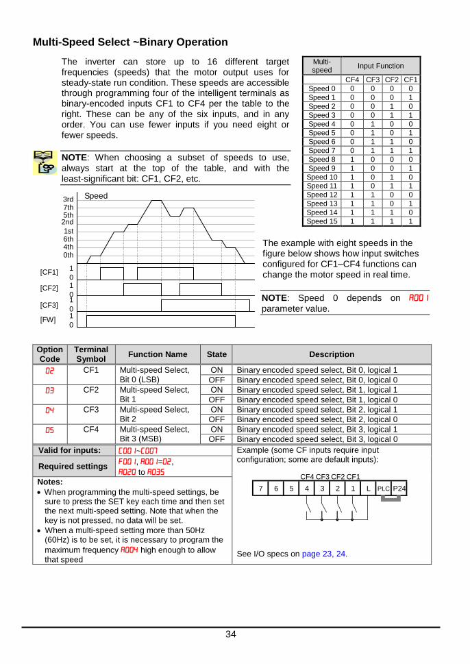
Multi-Speed Select ~Binary Operation
The inverter can store up to 16 different target frequencies (speeds) that the motor output uses for steady-state run condition. These speeds are accessible through programming four of the intelligent terminals as binary-encoded inputs CF1 to CF4 per the table to the right. These can be any of the six inputs, and in any order. You can use fewer inputs if you need eight or fewer speeds.
NOTE: When choosing a subset of speeds to use, always start at the top of the table, and with the least-significant bit: CF1, CF2, etc.
The example with eight speeds in the figure below shows how input switches configured for CF1–CF4 functions can change the motor speed in real time.
NOTE: Speed 0 depends on
parameter value.
Option Code
Terminal Symbol
Function Name State Description
CF1 Multi-speed Select, Bit 0 (LSB)
ON Binary encoded speed select, Bit 0, logical 1
OFF Binary encoded speed select, Bit 0, logical 0
CF2 Multi-speed Select, Bit 1
ON Binary encoded speed select, Bit 1, logical 1
OFF Binary encoded speed select, Bit 1, logical 0
CF3 Multi-speed Select, Bit 2
ON Binary encoded speed select, Bit 2, logical 1
OFF Binary encoded speed select, Bit 2, logical 0
CF4 Multi-speed Select, Bit 3 (MSB)
ON Binary encoded speed select, Bit 3, logical 1
OFF Binary encoded speed select, Bit 3, logical 0
Valid for inputs: ~ Example (some CF inputs require input configuration; some are default inputs): See I/O specs on page 23, 24.
Required settings , =,
to
Notes:
When programming the multi-speed settings, be sure to press the SET key each time and then set the next multi-speed setting. Note that when the key is not pressed, no data will be set.
When a multi-speed setting more than 50Hz (60Hz) is to be set, it is necessary to program the
maximum frequency high enough to allow that speed
Multi- speed
Input Function
CF4 CF3 CF2 CF1
Speed 0 0 0 0 0
Speed 1 0 0 0 1
Speed 2 0 0 1 0
Speed 3 0 0 1 1
Speed 4 0 1 0 0
Speed 5 0 1 0 1
Speed 6 0 1 1 0
Speed 7 0 1 1 1
Speed 8 1 0 0 0
Speed 9 1 0 0 1
Speed 10 1 0 1 0
Speed 11 1 0 1 1
Speed 12 1 1 0 0
Speed 13 1 1 0 1
Speed 14 1 1 1 0
Speed 15 1 1 1 1
Speed
0th 4th 6th 1st
2nd 5th 7th 3rd
1
0 1
0 1
0 1
0
[CF1]
[CF2]
[CF3]
[FW]
CF4 CF3 CF2 CF1
7 6 5 4 3 2 1 L P24 PLC

35
Two Stage Acceleration and Deceleration
When terminal [2CH] is turned ON, the inverter changes the rate of acceleration and
deceleration from the initial settings ( and
) to use the second set of acceleration/ deceleration values. When the terminal is turned OFF, the inverter is returned to the original acceleration and deceleration time
( acceleration time 1, and
deceleration time 1). Use (acceleration
time 2) and (deceleration time 2) to set the second stage acceleration and deceleration times.
In the graph shown above, the [2CH] becomes active during the initial acceleration. This
causes the inverter to switch from using acceleration 1 () to acceleration 2 ().
Option Code
Terminal Symbol
Function Name State Description
2CH Two-stage Accelera- tion and Deceleration
ON Frequency output uses 2nd-stage acceleration and deceleration values
OFF Frequency output uses the initial acceleration 1 and deceleration 1 values
Valid for inputs: ~ Example (requires input configuration see page 66): See I/O specs on page 23, 24.
Required settings , , =
Notes:
Function selects the method for second
stage acceleration. It must be set = to select the input terminal method in order for the [2CH] terminal assignment to operate.
[2CH] 1
0
Output frequency
t
[FW,RV] 1
0
Target frequency
initial
second
2CH
7 6 5 4 3 2 1 L P24 PLC
36
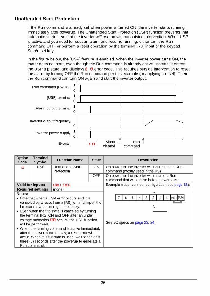
Unattended Start Protection
If the Run command is already set when power is turned ON, the inverter starts running immediately after powerup. The Unattended Start Protection (USP) function prevents that automatic startup, so that the inverter will not run without outside intervention. When USP is active and you need to reset an alarm and resume running, either turn the Run command OFF, or perform a reset operation by the terminal [RS] input or the keypad Stop/reset key.
In the figure below, the [USP] feature is enabled. When the inverter power turns ON, the motor does not start, even though the Run command is already active. Instead, it enters
the USP trip state, and displays error code. This requires outside intervention to reset the alarm by turning OFF the Run command per this example (or applying a reset). Then the Run command can turn ON again and start the inverter output.
Option Code
Terminal Symbol
Function Name State Description
USP Unattended Start Protection
ON On powerup, the inverter will not resume a Run command (mostly used in the US)
OFF On powerup, the inverter will resume a Run command that was active before power loss
Valid for inputs: ~ Example (requires input configuration see page 66): See I/O specs on page 23, 24.
Required settings (none)
Notes:
Note that when a USP error occurs and it is canceled by a reset from a [RS] terminal input, the inverter restarts running immediately.
Even when the trip state is canceled by turning the terminal [RS] ON and OFF after an under
voltage protection occurs, the USP function will be performed.
When the running command is active immediately after the power is turned ON, a USP error will occur. When this function is used, wait for at least three (3) seconds after the powerup to generate a Run command.
Inverter output frequency
0
t
Inverter power supply 1
0
Alarm output terminal 1
0
[USP] terminal 1
0
Run command [FW,RV] 1
0
Events: Alarm
cleared Run
command
USP
7 6 5 4 3 2 1 L P24 PLC

37
Reset Inverter
The [RS] terminal causes the inverter to execute the reset operation. If the inverter is in Trip Mode, the reset cancels the Trip state. When the signal [RS] is turned ON and OFF, the inverter executes the reset operation. The minimum pulse width for [RS] must be 12 ms or greater. The alarm output will be cleared within 30 ms after the onset of the Reset command.
WARNING: After the Reset command is given and the alarm reset occurs, the motor will restart suddenly if the Run command is already active. Be sure to set the alarm reset after verifying that the Run command is OFF to prevent injury to personnel.
Option Code
Terminal Symbol
Function Name State Description
RS Reset Inverter ON The motor output is turned OFF, the Trip Mode is cleared (if it exists), and powerup reset is applied
OFF Normal power ON operation
Valid for inputs: ~ Example (default input configuration shown see page 66): See I/O specs on page 23, 24.
Required settings (none)
Notes:
While the control terminal [RS] input is ON, the keypad displays alternating segments. After RS turns OFF, the display recovers automatically.
Pressing the Stop/Reset key of the digital operator can generate a reset operation only when an alarm occurs.
A terminal configured with the [RS] function can only be configured for normally open operation. The terminal cannot be used in the normally closed contact state.
When input power is turned ON, the inverter performs the same reset operation as it does when a pulse on the [RS] terminal occurs.
The Stop/Reset key on the inverter is only operational for a few seconds after inverter powerup when a hand-held remote operator is connected to the inverter.
If the [RS] terminal is turned ON while the motor is running, the motor will be free running (coasting).
If you are using the output terminal OFF delay feature (any of , , > 0.0 sec.), the [RS] terminal affects the ON-to-OFF transition slightly. Normally (without using OFF delays), the [RS] input causes the motor output and the logic outputs to turn OFF together, immediately. However, when any output uses an OFF delay, then after the [RS] input turns ON, that output will remain ON for an additional 1 sec. period (approximate) before turning OFF.
[RS] 1
0
t
Alarm signal
1
0
Approx. 30 ms
12 ms minimum
RS
7 6 5 4 3 2 1 L P24 PLC rt bar PLC

38
Using Intelligent Output Terminals
Run Signal
When the [RUN] signal is selected as an intelligent output terminal, the inverter outputs a signal on that terminal when it is in Run Mode. The output logic is active low, and is the open collector type (switch to ground).
Option Code
Terminal Symbol
Function Name State Description
RUN Run Signal ON when inverter is in Run Mode
OFF when inverter is in Stop Mode
Valid for inputs: 11, 12, AL0 – AL2 Example for terminal [11] (default output configuration shown see page 66):
Example for terminal [AL0], [AL1], [AL2] (requires output configuration see page 66): See I/O specs on page 23, 24.
Required settings (none)
Notes:
The inverter outputs the [RUN] signal whenever the inverter output exceeds the start frequency
specified by parameter . The start frequency
is the initial inverter output frequency when it turns ON.
The example circuit for terminal [11] drives a relay coil. Note the use of a diode to prevent the negative going turn-off spike generated by the coil from damaging the inverter’s output transistor.
RY
Inverter output
terminal circuit
CM2 11
RUN
AL1
Power
supplyLoad
AL0 AL2
Inverter logic
circuit board
RUN
[FW,RV] 1
0
Output frequency
t
Run signal
start freq.
ON
39
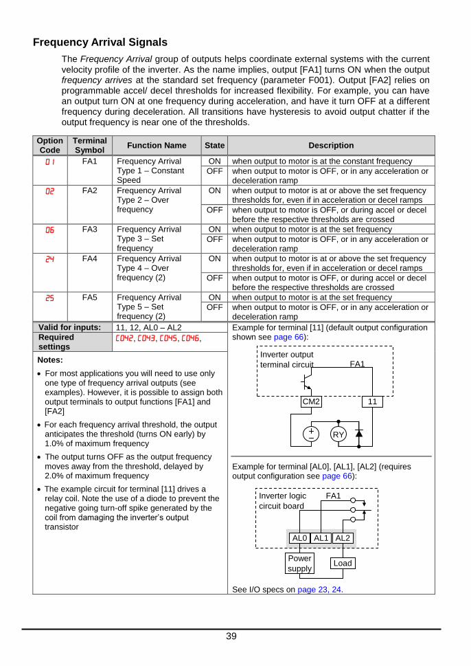
Frequency Arrival Signals
The Frequency Arrival group of outputs helps coordinate external systems with the current velocity profile of the inverter. As the name implies, output [FA1] turns ON when the output frequency arrives at the standard set frequency (parameter F001). Output [FA2] relies on programmable accel/ decel thresholds for increased flexibility. For example, you can have an output turn ON at one frequency during acceleration, and have it turn OFF at a different frequency during deceleration. All transitions have hysteresis to avoid output chatter if the output frequency is near one of the thresholds.
Option Code
Terminal Symbol
Function Name State Description
FA1 Frequency Arrival Type 1 – Constant Speed
ON when output to motor is at the constant frequency
OFF when output to motor is OFF, or in any acceleration or deceleration ramp
FA2 Frequency Arrival Type 2 – Over frequency
ON when output to motor is at or above the set frequency thresholds for, even if in acceleration or decel ramps
OFF when output to motor is OFF, or during accel or decel before the respective thresholds are crossed
FA3 Frequency Arrival Type 3 – Set frequency
ON when output to motor is at the set frequency
OFF when output to motor is OFF, or in any acceleration or deceleration ramp
FA4 Frequency Arrival Type 4 – Over frequency (2)
ON when output to motor is at or above the set frequency thresholds for, even if in acceleration or decel ramps
OFF when output to motor is OFF, or during accel or decel before the respective thresholds are crossed
FA5 Frequency Arrival Type 5 – Set frequency (2)
ON when output to motor is at the set frequency
OFF when output to motor is OFF, or in any acceleration or deceleration ramp
Valid for inputs: 11, 12, AL0 – AL2 Example for terminal [11] (default output configuration shown see page 66):
Example for terminal [AL0], [AL1], [AL2] (requires output configuration see page 66): See I/O specs on page 23, 24.
Required settings
, , , ,
Notes:
For most applications you will need to use only one type of frequency arrival outputs (see examples). However, it is possible to assign both output terminals to output functions [FA1] and [FA2]
For each frequency arrival threshold, the output anticipates the threshold (turns ON early) by 1.0% of maximum frequency
The output turns OFF as the output frequency moves away from the threshold, delayed by 2.0% of maximum frequency
The example circuit for terminal [11] drives a relay coil. Note the use of a diode to prevent the negative going turn-off spike generated by the coil from damaging the inverter’s output transistor
RY
Inverter output
terminal circuit
CM2 11
FA1
AL1
Power
supplyLoad
AL0 AL2
Inverter logic
circuit board
FA1
40
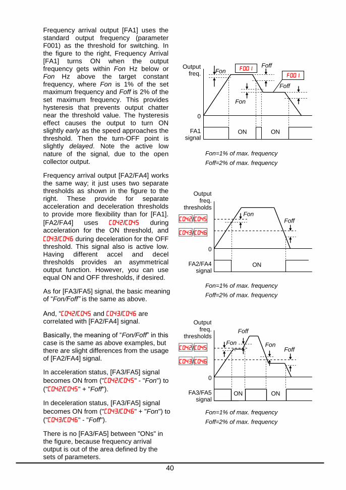
Frequency arrival output [FA1] uses the standard output frequency (parameter F001) as the threshold for switching. In the figure to the right, Frequency Arrival [FA1] turns ON when the output frequency gets within Fon Hz below or Fon Hz above the target constant frequency, where Fon is 1% of the set maximum frequency and Foff is 2% of the set maximum frequency. This provides hysteresis that prevents output chatter near the threshold value. The hysteresis effect causes the output to turn ON slightly early as the speed approaches the threshold. Then the turn-OFF point is slightly delayed. Note the active low nature of the signal, due to the open collector output.
Frequency arrival output [FA2/FA4] works the same way; it just uses two separate thresholds as shown in the figure to the right. These provide for separate acceleration and deceleration thresholds to provide more flexibility than for [FA1].
[FA2/FA4] uses / during acceleration for the ON threshold, and
/ during deceleration for the OFF threshold. This signal also is active low. Having different accel and decel thresholds provides an asymmetrical output function. However, you can use equal ON and OFF thresholds, if desired.
As for [FA3/FA5] signal, the basic meaning of “Fon/Foff” is the same as above.
And, “/ and / are correlated with [FA2/FA4] signal.
Basically, the meaning of “Fon/Foff” in this case is the same as above examples, but there are slight differences from the usage of [FA2/FA4] signal.
In acceleration status, [FA3/FA5] signal
becomes ON from ("/" - "Fon") to
("/" + "Foff").
In deceleration status, [FA3/FA5] signal
becomes ON from ("/" + "Fon") to
("/" - "Foff").
There is no [FA3/FA5] between "ONs" in the figure, because frequency arrival output is out of the area defined by the sets of parameters.
FA1 signal
Output freq. Fon
Foff
Fon
ON
Foff
ON
0
Fon=1% of max. frequency
Foff=2% of max. frequency
FA2/FA4 signal
Output freq.
thresholds
/
ON
0
/
Fon Foff
Fon=1% of max. frequency
Foff=2% of max. frequency
FA3/FA5 signal
Output freq.
thresholds
/
0
/
Fon Foff
Fon=1% of max. frequency
Foff=2% of max. frequency
Foff
Fon
ON ON
41
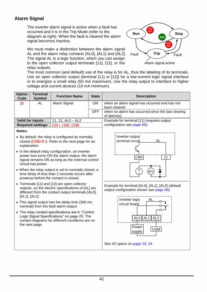
Alarm Signal
The inverter alarm signal is active when a fault has occurred and it is in the Trip Mode (refer to the diagram at right). When the fault is cleared the alarm signal becomes inactive.
We must make a distinction between the alarm signal AL and the alarm relay contacts [AL0], [AL1] and [AL2]. The signal AL is a logic function, which you can assign to the open collector output terminals [11], [12], or the relay outputs. The most common (and default) use of the relay is for AL, thus the labeling of its terminals. Use an open collector output (terminal [11] or [12]) for a low-current logic signal interface or to energize a small relay (50 mA maximum). Use the relay output to interface to higher voltage and current devices (10 mA minimum).
Option Code
Terminal Symbol
Function Name State Description
AL Alarm Signal ON when an alarm signal has occurred and has not been cleared
OFF when no alarm has occurred since the last clearing of alarm(s)
Valid for inputs: 11, 12, AL0 – AL2 Example for terminal [11] (requires output configuration see page 66):
Example for terminal [AL0], [AL1], [AL2] (default output configuration shown see page 66): See I/O specs on page 23, 24.
Required settings , ,
Notes:
By default, the relay is configured as normally
closed (=). Refer to the next page for an explanation.
In the default relay configuration, an inverter power loss turns ON the alarm output. the alarm signal remains ON as long as the external control circuit has power.
When the relay output is set to normally closed, a time delay of less than 2 seconds occurs after powerup before the contact is closed.
Terminals [11] and [12] are open collector outputs, so the electric specifications of [AL] are different from the contact output terminals [AL0], [AL1], [AL2].
This signal output has the delay time (300 ms nominal) from the fault alarm output.
The relay contact specifications are in “Control Logic Signal Specifications” on page 25. The contact diagrams for different conditions are on the next page.
Run Stop RUN
STOP
RESET
Trip
STOP
RESET
Fault Fault
Alarm signal active
RY
Inverter output
terminal circuit
CM2 11
AL
AL1
Power
supplyLoad
AL0 AL2
Inverter logic
circuit board
AL
42
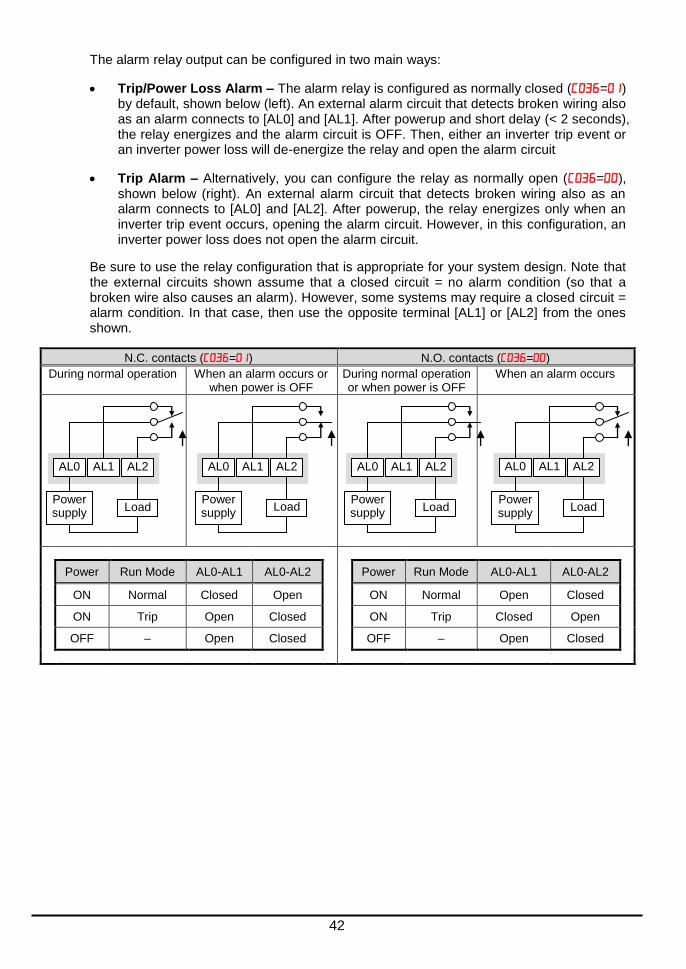
The alarm relay output can be configured in two main ways:
Trip/Power Loss Alarm – The alarm relay is configured as normally closed (=) by default, shown below (left). An external alarm circuit that detects broken wiring also as an alarm connects to [AL0] and [AL1]. After powerup and short delay (< 2 seconds), the relay energizes and the alarm circuit is OFF. Then, either an inverter trip event or an inverter power loss will de-energize the relay and open the alarm circuit
Trip Alarm – Alternatively, you can configure the relay as normally open (=), shown below (right). An external alarm circuit that detects broken wiring also as an alarm connects to [AL0] and [AL2]. After powerup, the relay energizes only when an inverter trip event occurs, opening the alarm circuit. However, in this configuration, an inverter power loss does not open the alarm circuit.
Be sure to use the relay configuration that is appropriate for your system design. Note that the external circuits shown assume that a closed circuit = no alarm condition (so that a broken wire also causes an alarm). However, some systems may require a closed circuit = alarm condition. In that case, then use the opposite terminal [AL1] or [AL2] from the ones shown.
N.C. contacts (=) N.O. contacts (=)
During normal operation When an alarm occurs or when power is OFF
During normal operation or when power is OFF
When an alarm occurs
Power Run Mode AL0-AL1 AL0-AL2 Power Run Mode AL0-AL1 AL0-AL2
ON Normal Closed Open ON Normal Open Closed
ON Trip Open Closed ON Trip Closed Open
OFF – Open Closed OFF – Open Closed
AL1
Power supply
Load
AL0 AL2 AL1
Power supply
Load
AL0 AL2 AL1
Power supply
Load
AL0 AL2 AL1
Power supply
Load
AL0 AL2

43
Analog Input Operation
The WL200 inverters provide for analog input to command the inverter frequency output value. The analog input terminal group includes the [L], [OI], [O], and [H] terminals on the control connector, which provide for Voltage [O] or Current [OI] input. All analog input signals must use the analog ground [L].
If you use either the voltage or current analog input, you must select one of them using the logic input terminal function [AT] analog type. Refer to the table on next page showing the activation of
each analog input by combination of set parameter and [AT] terminal condition. The [AT] terminal function is covered in “Analog Input Current/Voltage Select” in section 4. Remember
that you must also set = to select analog input as the frequency source.
NOTE: If no logic input terminal is configured for the [AT] function, then inverter recognizes
that [AT]=OFF and MCU recognizes [O]+[OI] as analog input.
Using an external potentiometer is a common way to control the inverter output frequency (and a good way to learn how to use the analog inputs). The potentiometer uses the built-in 10V reference [H] and the analog ground [L] for excitation, and the voltage input [O] for the signal. By default, the [AT] terminal selects the voltage input when it is OFF. Take care to use the proper resistance for the potentiometer, which is 1~2 k, 2 Watts.
Voltage Input – The voltage input circuit uses terminals [L] and [O]. Attach the signal cable’s shield wire only to terminal [L] on the inverter. Maintain the voltage within specifications (do not apply negative voltage).
Current Input – The current input circuit uses terminals [OI] and [L]. The current comes from a sourcing type transmitter; a sinking type will not work! This means the current must flow into terminal [OI], and terminal [L] is the return back to the transmitter. The input impedance from [OI] to [L] is 100 Ohms. Attach the cable shield wire only to terminal [L] on the inverter.
AM H O OI L
+V Ref.
Voltage input
Current input
A GND
AM H O OI L
Freq. setting
V/I input select
[AT]
+ -
4-20 mA
0-10 V
AM H O OI L
1 to 2k, 2W
0 to 9.6 VDC, 0 to 10V nominal
AM H O OI L
+ -
4 to 19.6 mA DC, 4 to 20mA nominal
AM H O OI L
See I/O specs on page 23, 24.
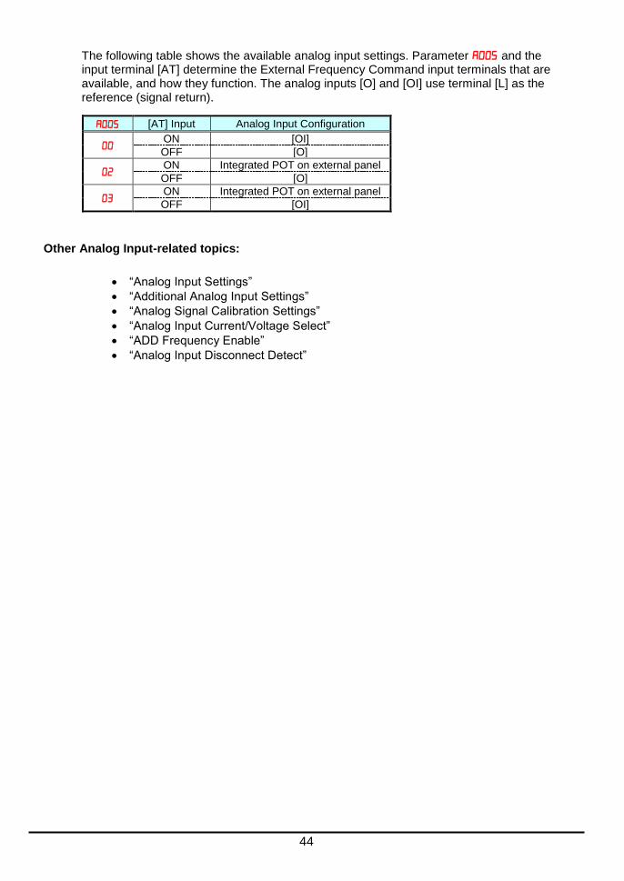
44
The following table shows the available analog input settings. Parameter and the input terminal [AT] determine the External Frequency Command input terminals that are available, and how they function. The analog inputs [O] and [OI] use terminal [L] as the reference (signal return).
[AT] Input Analog Input Configuration
ON [OI]
OFF [O]
ON Integrated POT on external panel
OFF [O]
ON Integrated POT on external panel
OFF [OI]
Other Analog Input-related topics:
“Analog Input Settings”
“Additional Analog Input Settings”
“Analog Signal Calibration Settings”
“Analog Input Current/Voltage Select”
“ADD Frequency Enable”
“Analog Input Disconnect Detect”
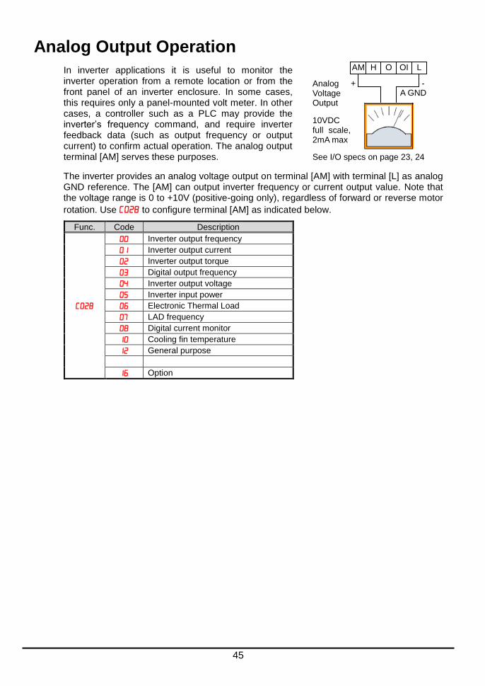
45
Analog Output Operation
In inverter applications it is useful to monitor the inverter operation from a remote location or from the front panel of an inverter enclosure. In some cases, this requires only a panel-mounted volt meter. In other cases, a controller such as a PLC may provide the inverter’s frequency command, and require inverter feedback data (such as output frequency or output current) to confirm actual operation. The analog output terminal [AM] serves these purposes.
The inverter provides an analog voltage output on terminal [AM] with terminal [L] as analog GND reference. The [AM] can output inverter frequency or current output value. Note that the voltage range is 0 to +10V (positive-going only), regardless of forward or reverse motor
rotation. Use to configure terminal [AM] as indicated below.
Func. Code Description
Inverter output frequency
Inverter output current
Inverter output torque
Digital output frequency
Inverter output voltage
Inverter input power
Electronic Thermal Load
LAD frequency
Digital current monitor
Cooling fin temperature
General purpose
Option
AM H O OI L
+ - A GND
Analog Voltage Output
10VDC full scale, 2mA max
See I/O specs on page 23, 24

46
The [AM] signal offset and gain are adjustable, as indicated below.
Func. Description Range Default
[AM] output gain 0.~255. 100.
[AM] output offset 0.0~10.0 0.0
The graph below shows the effect of the gain and offset setting. To calibrate the [AM] output for your application (analog meter), follow the steps below:
1. Run the motor at the full scale speed.
a. If the analog meter represents output frequency, adjust offset () first, and then
use to set the voltage for full scale output.
b. If [AM] represents motor current, adjust offset () first, and then use to set the voltage for full scale output. Remember to leave room at the upper end of the range for increased current when the motor is under heavier loads.
NOTE: As mentioned above, first adjust the offset, and then adjust the gain. Otherwise the required performance cannot be obtained because of the parallel movement of the offset adjustment.
Full scale (FS) Hz or A
AM output
10V
0 1/2 FS
5V
=0~255
AM output gain adjustment
Full scale (FS) Hz or A
AM output
10V
0 1/2 FS
5V
=0~10
Parallel movement
AM output offset adjustment

47
Drive Parameter Setting Tables Monitoring functions
NOTE: Parameters marked with "" in A column are accessible even in inverter running. Parameters marked with "" in B column are accessible even in inverter running when in the high level access mode, which means that b031 is set to "10".
* Please change from" (Basic display)" to " (Full display)" in parameter (Function
code display restriction), in case some parameters cannot be displayed.
IMPORTANT
Please be sure to set the motor nameplate data into the appropriate parameters
to ensure proper operation and protection of the motor:
b012 is the motor overload protection value
A082 is the motor voltage selection
H003 is the motor kW capacity
H004 is the number of motor poles
Please refer to the appropriate pages in this guide and the Instruction Manual for further details.
“d” Function
A B Units Func. Code
Name Description
Output frequency monitor Real time display of output frequency to motor from 0.00 to 400.0Hz
If is set high, output frequency
() can be changed by up/down key with d001 monitoring.
Hz
Output current monitor Filtered display of output current to motor, range is 0.0 to 655.3 Ampere A
Rotation direction monitor Three different indications:
“”Forward
“”Stop
“”Reverse
Process variable (PV), PID feedback monitor
Displays the scaled PID process
variable (feedback) value ( is scale factor), 0.00 to 9999.00
% times constant
Intelligent input terminal status
Displays the state of the intelligent input terminals:
ON
OFF
7 6 5 4 3 2 1
Terminal numbers

48
“d” Function
A B Units Func. Code
Name Description
Intelligent output terminal status
Displays the state of the intelligent output terminals:
Scaled output frequency monitor
Displays the output frequency scaled
by the constant in . Decimal point indicates range: 0 to 3999
Hz times constant
Output voltage monitor Voltage of output to motor, Range is 0.0 to 600.0V
V
Input power monitor Displays the input power, range is 0.0 to 999.9 Kw
KW
Watt-hour monitor Displays watt-hour of the inverter, range is 0 to 9999000
Elapsed RUN time monitor Displays total time the inverter has been powered up in hours. Range is 0. to 9999. / 1000 to 9999(10000 to 99990) /
100 to 999 (100000 to 999000)
hours
Elapsed power-on time monitor
hours
Heat sink temperature monitor Temperature of the cooling fin, range is -20 to 150
C
Life check monitor Displays the state of lifetime of electrolytic capacitors on the PWB and cooling fan.
Program counter monitor [EzSQ]
Range is 0 to 1024
Program number monitor [EzSQ]
Range is 0 to 9999
User monitor 0 [EzSQ]
Result of EzSQ execution, range is –2147483647 to 2147483647
User monitor 1 [EzSQ]
Result of EzSQ execution, range is –2147483647 to 2147483647
User monitor 2 [EzSQ]
Result of EzSQ execution, range is –2147483647 to 2147483647
Dual monitor Displays two different data
configured in and .
Lifetime expired
Normal
Electrolytic caps Cooling fan
ON
OFF
Relay 12 11
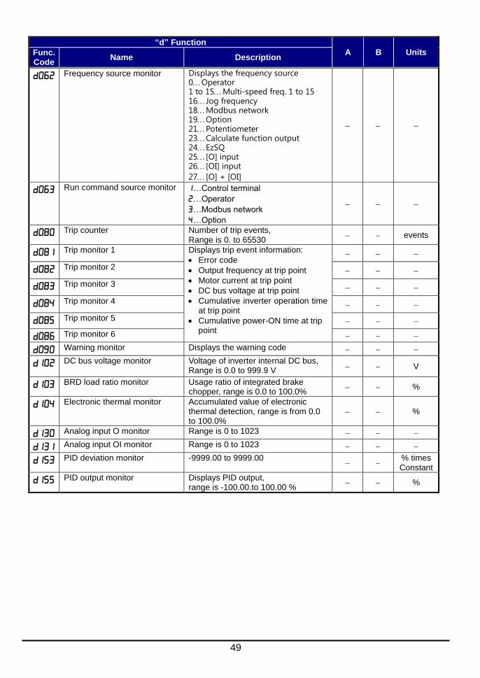
49
“d” Function
A B Units Func. Code
Name Description
Frequency source monitor Displays the frequency source 0Operator 1 to 15Multi-speed freq. 1 to 15 16Jog frequency 18Modbus network 19Option 21Potentiometer 23Calculate function output 24EzSQ 25[O] input 26[OI] input
27[O] + [OI]
Run command source monitor …Control terminal
…Operator
…Modbus network
…Option
Trip counter Number of trip events, Range is 0. to 65530
events
Trip monitor 1 Displays trip event information:
Error code
Output frequency at trip point
Motor current at trip point
DC bus voltage at trip point
Cumulative inverter operation time at trip point
Cumulative power-ON time at trip point
Trip monitor 2
Trip monitor 3
Trip monitor 4
Trip monitor 5
Trip monitor 6
Warning monitor Displays the warning code
DC bus voltage monitor Voltage of inverter internal DC bus, Range is 0.0 to 999.9 V V
BRD load ratio monitor Usage ratio of integrated brake chopper, range is 0.0 to 100.0%
%
Electronic thermal monitor Accumulated value of electronic thermal detection, range is from 0.0 to 100.0%
%
Analog input O monitor Range is 0 to 1023
Analog input OI monitor Range is 0 to 1023
PID deviation monitor -9999.00 to 9999.00
% times Constant
PID output monitor Displays PID output, range is -100.00.to 100.00 %
%

50
Main Profile Parameters
NOTE:. Parameters marked with "" in A column are accessible even in inverter running. Parameters marked with "" in B column are accessible even in inverter running when in the high level access mode, which means that b031 is set to "10".
“F” Function
A B
Defaults
Func. Code
Name Description Initial data Units
Output frequency setting Standard default target frequency that determines constant motor speed, range is 0.0 / start frequency to maximum frequency (A004)
0.00 Hz
Acceleration time (1) Standard default acceleration, range is 0.00 to 3600 sec. 10.00 s
Acceleration time (1), 2
nd motor 10.00 s
Deceleration time (1) Standard default deceleration, range is 0.00 to 3600 sec. 10.00 s
Deceleration time (1), 2
nd motor 10.00 s
Keypad RUN key routing Two options; select codes:
Forward
Reverse 00
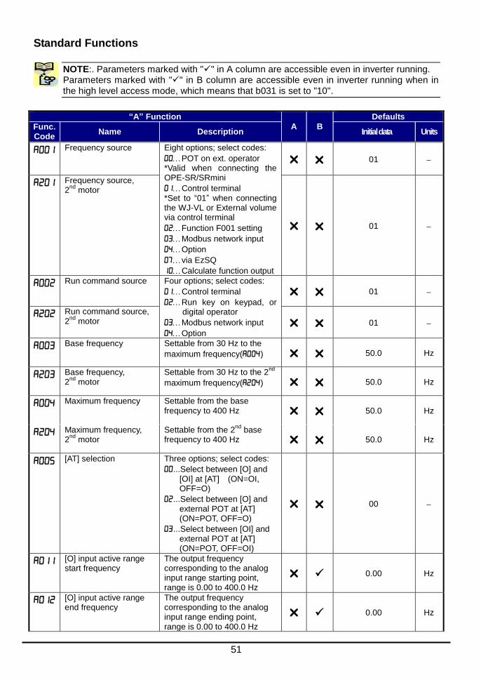
51
Standard Functions
NOTE:. Parameters marked with "" in A column are accessible even in inverter running. Parameters marked with "" in B column are accessible even in inverter running when in the high level access mode, which means that b031 is set to "10".
“A” Function
A B
Defaults
Func. Code
Name Description Initial data Units
Frequency source Eight options; select codes:
POT on ext. operator *Valid when connecting the OPE-SR/SRmini
Control terminal *Set to “01” when connecting the WJ-VL or External volume via control terminal
Function F001 setting
Modbus network input
Option
via EzSQ
Calculate function output
01
Frequency source, 2
nd motor
01
Run command source Four options; select codes:
Control terminal
Run key on keypad, or digital operator
Modbus network input
Option
01
Run command source, 2
nd motor 01
Base frequency Settable from 30 Hz to the
maximum frequency() 50.0 Hz
Base frequency, 2
nd motor
Settable from 30 Hz to the 2nd
maximum frequency() 50.0 Hz
Maximum frequency Settable from the base frequency to 400 Hz 50.0 Hz
Maximum frequency, 2
nd motor
Settable from the 2nd
base frequency to 400 Hz 50.0 Hz
[AT] selection Three options; select codes:
...Select between [O] and [OI] at [AT] (ON=OI, OFF=O)
...Select between [O] and external POT at [AT] (ON=POT, OFF=O)
...Select between [OI] and external POT at [AT] (ON=POT, OFF=OI)
00
[O] input active range start frequency
The output frequency corresponding to the analog input range starting point, range is 0.00 to 400.0 Hz
0.00 Hz
[O] input active range end frequency
The output frequency corresponding to the analog input range ending point, range is 0.00 to 400.0 Hz
0.00 Hz

52
“A” Function
A B
Defaults
Func. Code
Name Description Initial data Units
[O] input active range start voltage
The starting point (offset) for the active analog input range, range is 0. to 100 %.
0. %
[O] input active range end voltage
The ending point (offset) for the active analog input range, range is 0. to 100.%
100. %
[O] input start frequency enable
Two options; select codes:
Use offset ( value)
Use 0 Hz
01
Analog input filter Range n = 1 to 31,
1 to 30 : ×2ms filter
31: 500ms fixed filter with ±0.1 kHz hysteresis.
8. Spl.
EzSQ function select Select codes:
Disable
Activate by PRG terminal
Activate always
00 -
Multi-speed operation selection
Select codes:
...Binary operation (16 speeds selectable with 4 terminals)
...Bit operation (8 speeds selectable with 7 terminals)
00 -
Multi-speed freq. 0 Defines the first speed of a multi-speed profile, range is 0.00 / start frequency to 400 Hz
6.0 Hz
Multi-speed freq. 0, 2
nd motor
Defines the first speed of a multi-speed profile or a 2nd motor, range is 0.00 / start frequency to 400 Hz
6.0 Hz
to
Multi-speed freq. 1 to 15 (for both motors)
Defines 15 more speeds, range is 0.00 / start frequency to 400 Hz.
=Speed 1 to
=Speed15
0.0 Hz
Jog frequency Defines limited speed for jog, range is from start frequency to 9.99 Hz
6.00 Hz
Jog stop mode Define how end of jog stops the motor; six options:
Free-run stop (invalid during run)
Controlled deceleration (invalid during run)
DC braking to stop(invalid during run)
Free-run stop (valid during run)
Controlled deceleration (valid during run)
DC braking to stop(valid during run)
04
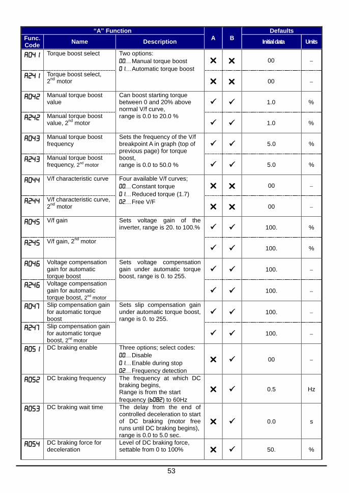
53
“A” Function
A B
Defaults
Func. Code
Name Description Initial data Units
Torque boost select Two options:
Manual torque boost
Automatic torque boost
00
Torque boost select, 2
nd motor 00
Manual torque boost value
Can boost starting torque between 0 and 20% above normal V/f curve, range is 0.0 to 20.0 %
1.0 %
Manual torque boost value, 2
nd motor 1.0 %
Manual torque boost frequency
Sets the frequency of the V/f breakpoint A in graph (top of previous page) for torque boost, range is 0.0 to 50.0 %
5.0 %
Manual torque boost frequency, 2nd
motor 5.0 %
V/f characteristic curve Four available V/f curves;
Constant torque
Reduced torque (1.7)
Free V/F
00
V/f characteristic curve, 2
nd motor 00
V/f gain Sets voltage gain of the inverter, range is 20. to 100.% 100. %
V/f gain, 2nd
motor
100. %
Voltage compensation gain for automatic torque boost
Sets voltage compensation gain under automatic torque boost, range is 0. to 255.
100.
Voltage compensation gain for automatic torque boost, 2nd
motor 100.
Slip compensation gain for automatic torque boost
Sets slip compensation gain under automatic torque boost, range is 0. to 255.
100.
Slip compensation gain for automatic torque boost, 2nd
motor 100.
DC braking enable Three options; select codes:
Disable
Enable during stop
Frequency detection
00
DC braking frequency The frequency at which DC braking begins, Range is from the start
frequency () to 60Hz
0.5 Hz
DC braking wait time The delay from the end of controlled deceleration to start of DC braking (motor free runs until DC braking begins), range is 0.0 to 5.0 sec.
0.0 s
DC braking force for deceleration
Level of DC braking force, settable from 0 to 100% 50. %
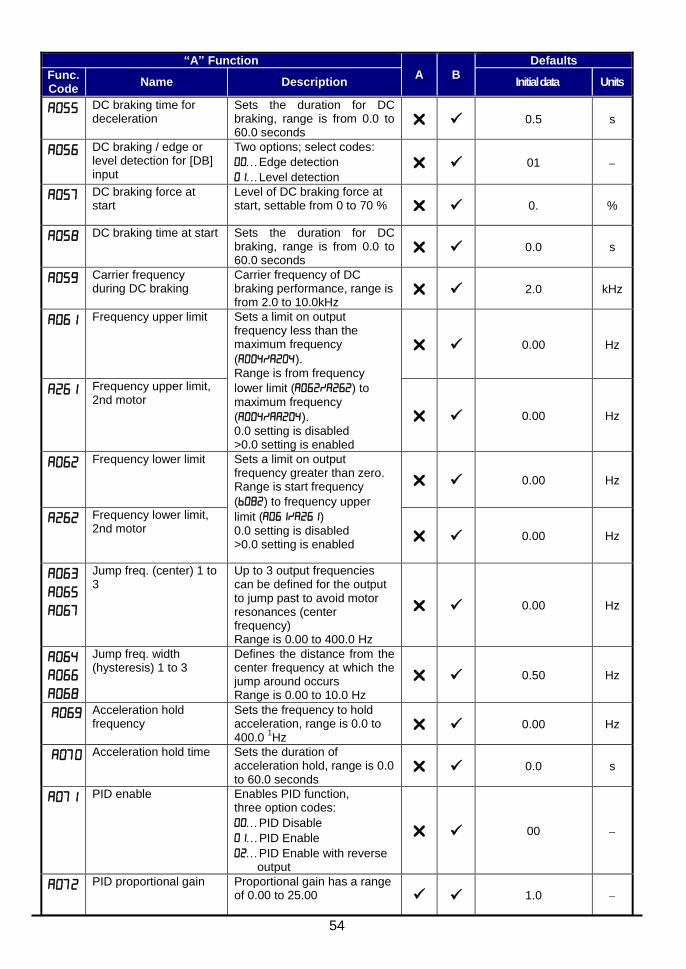
54
“A” Function
A B
Defaults
Func. Code
Name Description Initial data Units
DC braking time for deceleration
Sets the duration for DC braking, range is from 0.0 to 60.0 seconds
0.5 s
DC braking / edge or level detection for [DB] input
Two options; select codes:
Edge detection
Level detection
01
DC braking force at start
Level of DC braking force at start, settable from 0 to 70 % 0. %
DC braking time at start Sets the duration for DC braking, range is from 0.0 to 60.0 seconds
0.0 s
Carrier frequency during DC braking
Carrier frequency of DC braking performance, range is from 2.0 to 10.0kHz
2.0 kHz
Frequency upper limit
Sets a limit on output frequency less than the maximum frequency
(). Range is from frequency
lower limit () to maximum frequency
(). 0.0 setting is disabled >0.0 setting is enabled
0.00 Hz
Frequency upper limit, 2nd motor
0.00 Hz
Frequency lower limit
Sets a limit on output frequency greater than zero. Range is start frequency
() to frequency upper
limit () 0.0 setting is disabled >0.0 setting is enabled
0.00 Hz
Frequency lower limit, 2nd motor
0.00 Hz
Jump freq. (center) 1 to 3
Up to 3 output frequencies can be defined for the output to jump past to avoid motor resonances (center frequency) Range is 0.00 to 400.0 Hz
0.00 Hz
Jump freq. width (hysteresis) 1 to 3
Defines the distance from the center frequency at which the jump around occurs Range is 0.00 to 10.0 Hz
0.50 Hz
Acceleration hold frequency
Sets the frequency to hold acceleration, range is 0.0 to 400.0
1Hz
0.00 Hz
Acceleration hold time Sets the duration of acceleration hold, range is 0.0 to 60.0 seconds
0.0 s
PID enable Enables PID function, three option codes:
PID Disable
PID Enable
PID Enable with reverse output
00
PID proportional gain Proportional gain has a range of 0.00 to 25.00 1.0
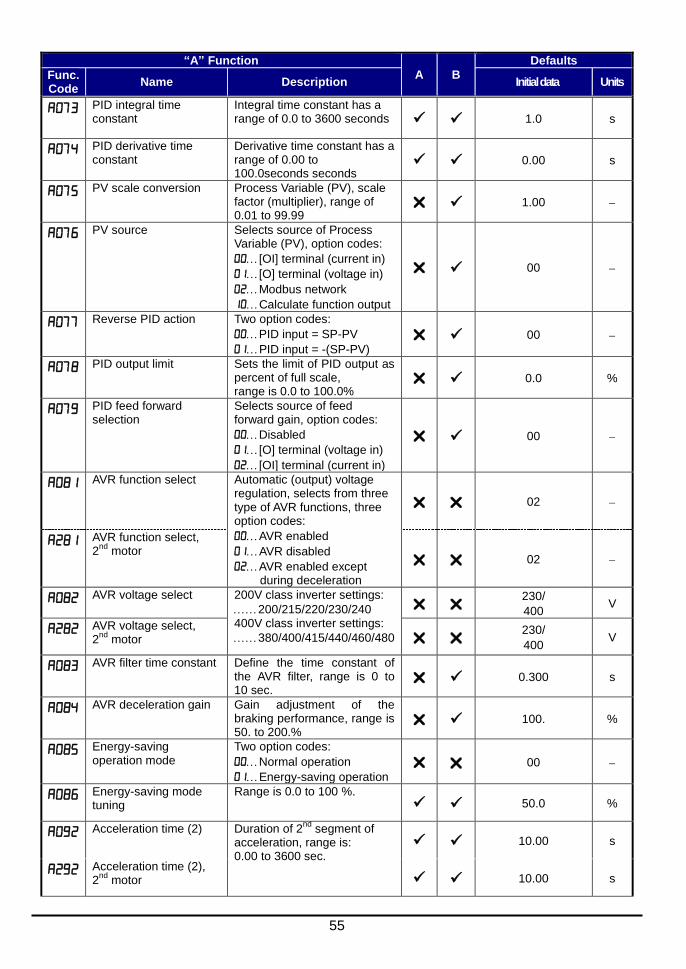
55
“A” Function
A B
Defaults
Func. Code
Name Description Initial data Units
PID integral time constant
Integral time constant has a range of 0.0 to 3600 seconds 1.0 s
PID derivative time constant
Derivative time constant has a range of 0.00 to 100.0seconds seconds
0.00 s
PV scale conversion Process Variable (PV), scale factor (multiplier), range of 0.01 to 99.99
1.00
PV source Selects source of Process Variable (PV), option codes:
[OI] terminal (current in)
[O] terminal (voltage in)
Modbus network
Calculate function output
00
Reverse PID action Two option codes:
PID input = SP-PV
PID input = -(SP-PV)
00
PID output limit Sets the limit of PID output as percent of full scale, range is 0.0 to 100.0%
0.0 %
PID feed forward selection
Selects source of feed forward gain, option codes:
Disabled
[O] terminal (voltage in)
[OI] terminal (current in)
00
AVR function select Automatic (output) voltage regulation, selects from three type of AVR functions, three option codes:
AVR enabled
AVR disabled
AVR enabled except during deceleration
02
AVR function select, 2
nd motor
02
AVR voltage select 200V class inverter settings:
200/215/220/230/240 400V class inverter settings:
380/400/415/440/460/480
230/
400 V
AVR voltage select, 2
nd motor
230/
400 V
AVR filter time constant Define the time constant of the AVR filter, range is 0 to 10 sec.
0.300 s
AVR deceleration gain Gain adjustment of the braking performance, range is 50. to 200.%
100. %
Energy-saving operation mode
Two option codes:
Normal operation
Energy-saving operation
00
Energy-saving mode tuning
Range is 0.0 to 100 %. 50.0 %
Acceleration time (2) Duration of 2nd
segment of acceleration, range is: 0.00 to 3600 sec.
10.00 s
Acceleration time (2), 2
nd motor 10.00 s
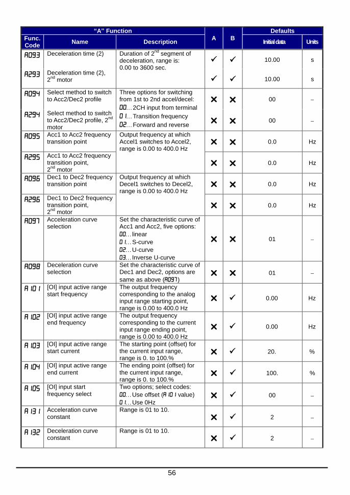
56
“A” Function
A B
Defaults
Func. Code
Name Description Initial data Units
Deceleration time (2) Duration of 2nd
segment of deceleration, range is: 0.00 to 3600 sec.
10.00 s
Deceleration time (2), 2
nd motor 10.00 s
Select method to switch to Acc2/Dec2 profile
Three options for switching from 1st to 2nd accel/decel:
2CH input from terminal
Transition frequency
Forward and reverse
00
Select method to switch to Acc2/Dec2 profile, 2
nd
motor 00
Acc1 to Acc2 frequency transition point
Output frequency at which Accel1 switches to Accel2, range is 0.00 to 400.0 Hz
0.0 Hz
Acc1 to Acc2 frequency transition point, 2
nd motor
0.0 Hz
Dec1 to Dec2 frequency transition point
Output frequency at which Decel1 switches to Decel2, range is 0.00 to 400.0 Hz
0.0 Hz
Dec1 to Dec2 frequency transition point, 2
nd motor
0.0 Hz
Acceleration curve selection
Set the characteristic curve of Acc1 and Acc2, five options:
linear
S-curve
U-curve
Inverse U-curve
01
Deceleration curve selection
Set the characteristic curve of Dec1 and Dec2, options are
same as above () 01
[OI] input active range start frequency
The output frequency corresponding to the analog input range starting point, range is 0.00 to 400.0 Hz
0.00 Hz
[OI] input active range end frequency
The output frequency corresponding to the current input range ending point, range is 0.00 to 400.0 Hz
0.00 Hz
[OI] input active range start current
The starting point (offset) for the current input range, range is 0. to 100.%
20. %
[OI] input active range end current
The ending point (offset) for the current input range, range is 0. to 100.%
100. %
[OI] input start frequency select
Two options; select codes:
Use offset ( value)
Use 0Hz 00
Acceleration curve constant
Range is 01 to 10.
2
Deceleration curve constant
Range is 01 to 10.
2
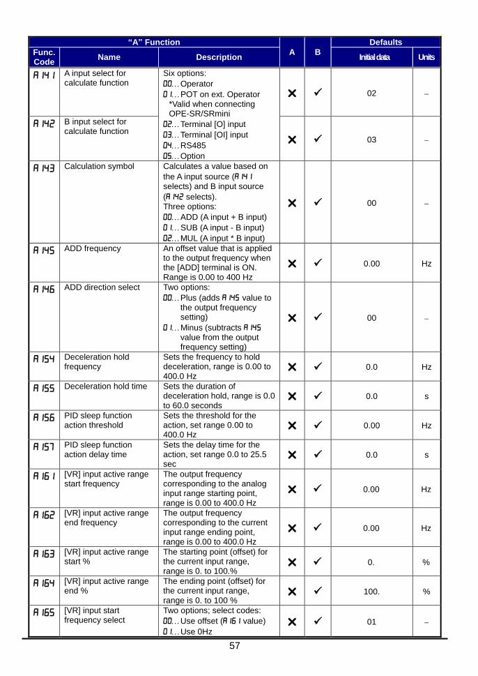
57
“A” Function
A B
Defaults
Func. Code
Name Description Initial data Units
A input select for calculate function
Six options:
Operator
POT on ext. Operator *Valid when connecting OPE-SR/SRmini
Terminal [O] input
Terminal [OI] input
RS485
Option
02
B input select for calculate function
03
Calculation symbol Calculates a value based on
the A input source ( selects) and B input source
( selects). Three options:
ADD (A input + B input)
SUB (A input - B input)
MUL (A input * B input)
00
ADD frequency An offset value that is applied to the output frequency when the [ADD] terminal is ON. Range is 0.00 to 400 Hz
0.00 Hz
ADD direction select Two options:
Plus (adds value to the output frequency setting)
Minus (subtracts value from the output frequency setting)
00
Deceleration hold frequency
Sets the frequency to hold deceleration, range is 0.00 to 400.0 Hz
0.0 Hz
Deceleration hold time Sets the duration of deceleration hold, range is 0.0 to 60.0 seconds
0.0 s
PID sleep function action threshold
Sets the threshold for the action, set range 0.00 to 400.0 Hz
0.00 Hz
PID sleep function action delay time
Sets the delay time for the action, set range 0.0 to 25.5 sec
0.0 s
[VR] input active range start frequency
The output frequency corresponding to the analog input range starting point, range is 0.00 to 400.0 Hz
0.00 Hz
[VR] input active range end frequency
The output frequency corresponding to the current input range ending point, range is 0.00 to 400.0 Hz
0.00 Hz
[VR] input active range start %
The starting point (offset) for the current input range, range is 0. to 100.%
0. %
[VR] input active range end %
The ending point (offset) for the current input range, range is 0. to 100 %
100. %
[VR] input start frequency select
Two options; select codes:
Use offset ( value)
Use 0Hz 01
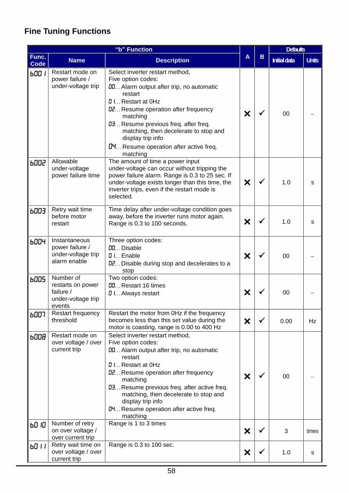
58
Fine Tuning Functions
“b” Function
A B
Defaults
Func. Code
Name Description Initial data Units
Restart mode on power failure / under-voltage trip
Select inverter restart method, Five option codes:
Alarm output after trip, no automatic restart
Restart at 0Hz
Resume operation after frequency matching
Resume previous freq. after freq. matching, then decelerate to stop and display trip info
Resume operation after active freq.
matching
00
Allowable under-voltage power failure time
The amount of time a power input under-voltage can occur without tripping the power failure alarm. Range is 0.3 to 25 sec. If under-voltage exists longer than this time, the inverter trips, even if the restart mode is selected.
1.0 s
Retry wait time before motor restart
Time delay after under-voltage condition goes away, before the inverter runs motor again. Range is 0.3 to 100 seconds. 1.0 s
Instantaneous power failure / under-voltage trip alarm enable
Three option codes:
Disable
Enable
Disable during stop and decelerates to a stop
00
Number of restarts on power failure / under-voltage trip events
Two option codes:
Restart 16 times
Always restart 00
Restart frequency threshold
Restart the motor from 0Hz if the frequency becomes less than this set value during the motor is coasting, range is 0.00 to 400 Hz
0.00 Hz
Restart mode on over voltage / over current trip
Select inverter restart method, Five option codes:
Alarm output after trip, no automatic restart
Restart at 0Hz
Resume operation after frequency matching
Resume previous freq. after active freq. matching, then decelerate to stop and display trip info
Resume operation after active freq. matching
00
Number of retry on over voltage / over current trip
Range is 1 to 3 times
3 times
Retry wait time on over voltage / over current trip
Range is 0.3 to 100 sec.
1.0 s

59
“b” Function
A B
Defaults
Func. Code
Name Description Initial data Units
Level of electronic thermal
Set a level between 20% and 100% of the rated inverter current.
Rated current for
each inverter model
A
Level of electronic thermal, 2
nd motor
A
Electronic thermal characteristic
Select from three curves, option codes:
Reduced torque
Constant torque
Free setting
01
Electronic thermal characteristic, 2
nd motor
01
Free setting electronic thermal ~freq.1
Range is 0 to 400 Hz
0.0 Hz
Free setting electronic thermal ~current1
Range is 0 to inverter rated current Amps
0.00 A
Free setting electronic thermal ~freq.2
Range is 0 to 400 Hz
0.0 Hz
Free setting electronic thermal ~current2
Range is 0 to inverter rated current Amps
0.00 A
Free setting electronic thermal ~freq.3
Range is 0 to 400 Hz
0.0 Hz
Free setting electronic thermal ~current3
Range is 0 to inverter rated current Amps
0.00 A
Overload restriction operation mode
Select the operation mode during overload conditions, four options, option codes:
Disabled
Enabled for acceleration and constant speed
Enabled for constant speed only
Enabled for acceleration and constant speed, increase speed at regen.
01
Overload restriction operation mode, 2
nd motor
01
Overload restriction level
Sets the level of overload restriction, between 20 % and 150 % of the rated current of the inverter, setting resolution is 1 % of rated current
Rated current
x 1.2
A
Overload restriction level, 2
nd motor
Rated current
x 1.2
A
Deceleration rate at overload restriction
Sets the deceleration rate when inverter detects overload, range is 0.1 to 3000.0, resolution 0.1 1.0 s
Deceleration rate at overload restriction, 2
nd motor
1.0 s
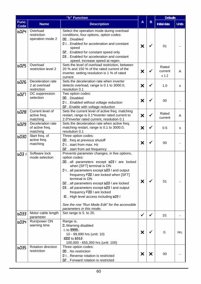
60
“b” Function
A B
Defaults
Func. Code
Name Description Initial data Units
Overload restriction operation mode 2
Select the operation mode during overload conditions, four options, option codes:
Disabled
Enabled for acceleration and constant speed
Enabled for constant speed only
Enabled for acceleration and constant speed, increase speed at regen.
01
Overload restriction level 2
Sets the level of overload restriction, between 20 % and 150 % of the rated current of the inverter, setting resolution is 1 % of rated current
Rated current
x 1.2
A
Deceleration rate 2 at overload restriction
Sets the deceleration rate when inverter detects overload, range is 0.1 to 3000.0, resolution 0.1
1.0 s
OC suppression selection
Two option codes:
Disabled
Enabled without voltage reduction
...Enable with voltage reduction
00
Current level of active freq. matching
Sets the current level of active freq. matching restart, range is 0.1*inverter rated current to 2.0*inverter rated current, resolution 0.1
Rated current
A
Deceleration rate of active freq. matching
Sets the deceleration rate when active freq. matching restart, range is 0.1 to 3000.0, resolution 0.1
0.5 s
Start freq. of active freq. matching
Three option codes:
freq at previous shutoff
start from max. Hz
start from set frequency
00
Software lock mode selection
Prevents parameter changes, in five options, option codes:
all parameters except are locked when [SFT] terminal is ON
all parameters except and output
frequency are locked when [SFT] terminal is ON
all parameters except are locked
all parameters except and output
frequency are locked
High level access including See the row “Run Mode Edit” for the accessible parameters in this mode.
01
Motor cable length parameter
Set range is 5. to 20. 10.
Run/power ON warning time
Range is,
.:Warning disabled
. to .:
10 - 99,990 hrs (unit: 10)
to : 100,000 - 655,350 hrs (unit: 100)
0. Hrs.
Rotation direction restriction
Three option codes:
No restriction
Reverse rotation is restricted
Forward rotation is restricted
00
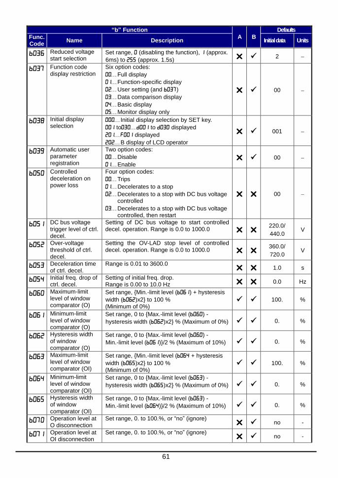
61
“b” Function
A B
Defaults
Func. Code
Name Description Initial data Units
Reduced voltage start selection
Set range, (disabling the function), (approx.
6ms) to (approx. 1.5s) 2
Function code display restriction
Six option codes:
Full display
Function-specific display
User setting (and )
Data comparison display
Basic display
Monitor display only
00
Initial display selection
Initial display selection by SET key.
to to displayed
displayed
B display of LCD operator
001
Automatic user parameter registration
Two option codes:
Disable
Enable 00
Controlled deceleration on power loss
Four option codes:
Trips
Decelerates to a stop
Decelerates to a stop with DC bus voltage controlled
Decelerates to a stop with DC bus voltage controlled, then restart
00
DC bus voltage trigger level of ctrl. decel.
Setting of DC bus voltage to start controlled decel. operation. Range is 0.0 to 1000.0
220.0/
440.0 V
Over-voltage threshold of ctrl. decel.
Setting the OV-LAD stop level of controlled decel. operation. Range is 0.0 to 1000.0
360.0/
720.0 V
Deceleration time of ctrl. decel.
Range is 0.01 to 3600.0 1.0 s
Initial freq. drop of ctrl. decel.
Setting of initial freq. drop. Range is 0.00 to 10.0 Hz 0.0 Hz
Maximum-limit level of window comparator (O)
Set range, {Min.-limit level () + hysteresis
width ()x2} to 100 % (Minimum of 0%)
100. %
Minimum-limit level of window comparator (O)
Set range, 0 to {Max.-limit level () -
hysteresis width ()x2} % (Maximum of 0%) 0. %
Hysteresis width of window comparator (O)
Set range, 0 to {Max.-limit level () -
Min.-limit level ()}/2 % (Maximum of 10%) 0. %
Maximum-limit level of window comparator (OI)
Set range, {Min.-limit level ( + hysteresis
width ()x2} to 100 % (Minimum of 0%)
100. %
Minimum-limit level of window comparator (OI)
Set range, 0 to {Max.-limit level () -
hysteresis width ()x2} % (Maximum of 0%) 0. %
Hysteresis width of window comparator (OI)
Set range, 0 to {Max.-limit level () -
Min.-limit level ()}/2 % (Maximum of 10%) 0. %
Operation level at O disconnection
Set range, 0. to 100.%, or “no” (ignore) no -
Operation level at OI disconnection
Set range, 0. to 100.%, or “no” (ignore) no -

62
“b” Function
A B
Defaults
Func. Code
Name Description Initial data Units
Ambient temperature setting
Set range is,
-10 to 50 C 40 C
Watt-hour clearance
Two option codes:
OFF
ON (press STR then clear) 00 -
Watt-hour display gain
Set range is, 1. to 1000. 1. -
Start frequency Sets the starting frequency for the inverter output, range is 0.10 to 9.99 Hz 0.50 Hz
Carrier frequency Sets the PWM carrier (internal switching frequency), range is 2.0 to 10.0 kHz 2.0 kHz
Initialization mode (parameters or trip history)
Select initialized data, five option codes:
Initialization disabled
Clears Trip history
Initializes all Parameters
Clears Trip history and initializes all parameters
Clears Trip history and initializes all parameters and EzSQ program
00
Country for initialization
Mode 1, Mode 0, Mode 3 01
Frequency scaling conversion factor
Specify a constant to scale the displayed
frequency for monitor, range is 0.01 to 99.99
1.00
STOP key enable Select whether the STOP key on the keypad is enabled, three option codes:
Enabled
Disabled always
Disabled for stop
00
Restart mode after FRS
Selects how the inverter resumes operation when free-run stop (FRS) is cancelled, three options:
Restart from 0Hz
Restart from frequency detected from real speed of motor (freq. matching)
Restart from frequency detected from real speed of motor (active freq. matching)
00
Automatic carrier frequency reduction
Three option codes:
Disabled
Enabled, depending on the output current
Enabled, depending on the heat-sink temperature
01 -
Dynamic braking usage ratio
Selects the rate of use (in %) of the regenerative braking resistor per 100 sec. intervals, range is 0.0 to the value calculated by the value of b097. If the connected resister’s allowable range is narrower then above range, the resister’s range is prior. 0%: Function disabled >0%: Enabled, per value
0.0 %
Stop mode selection
Select how the inverter stops the motor, two option codes:
DEC (decelerate to stop)
FRS (free-run to stop)
00
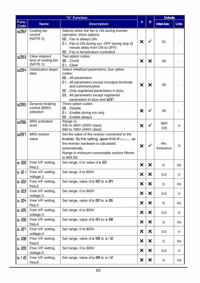
63
“b” Function
A B
Defaults
Func. Code
Name Description Initial data Units
Cooling fan control (NOTE 1)
Selects when the fan is ON during inverter operation, three options:
Fan is always ON
Fan is ON during run, OFF during stop (5 minute delay from ON to OFF)
Fan is temperature controlled
01 -
Clear elapsed time of cooling fan (NOTE 1)
Two option codes:
Count
Clear 00 -
Initialization target data
Select initialized parameters, four option codes:
All parameters
All parameters except in/output terminals and communication.
Only registered parameters in xxx.
All parameters except registered
parameters in xxx and .
00 -
Dynamic braking control (BRD) selection
Three option codes:
Disable
Enable during run only
Enable always
00 -
BRD activation level
Range is: 330 to 380V (200V class) 660 to 760V (400V class)
360/
720 V
BRD resistor
value
Set the value of the resistor connected to the
the inverter hardware is calculated
automatically.
Range is minimum connectable resistor Rbmin
to 600.0Ω
Min.
Resistance Ω
Free V/F setting,
freq.1
Set range, 0 to value of 0. Hz
Free V/F setting,
voltage.1
Set range, 0 to 800V 0.0 V
Free V/F setting,
freq.2
Set range, value of to 0. Hz
Free V/F setting,
voltage.2
Set range, 0 to 800V 0.0 V
Free V/F setting,
freq.3
Set range, value of to 0. Hz
Free V/F setting,
voltage.3
Set range, 0 to 800V 0.0 V
Free V/F setting,
freq.4
Set range, value of to 0. Hz
Free V/F setting,
voltage.4
Set range, 0 to 800V 0.0 V
Free V/F setting,
freq.5
Set range, value of to 0. Hz
Free V/F setting,
voltage.5
Set range, 0 to 800V 0.0 V
Free V/F setting,
freq.6
Set range, value of to 0. Hz
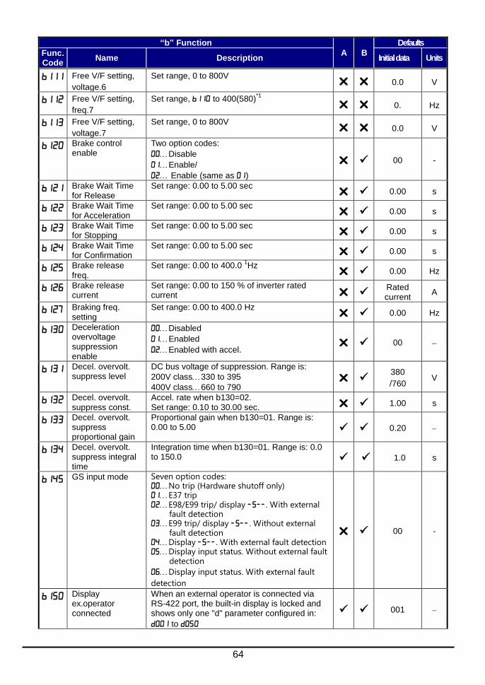
64
“b” Function
A B
Defaults
Func. Code
Name Description Initial data Units
Free V/F setting,
voltage.6
Set range, 0 to 800V 0.0 V
Free V/F setting,
freq.7
Set range, to 400(580)*1
0. Hz
Free V/F setting,
voltage.7
Set range, 0 to 800V 0.0 V
Brake control enable
Two option codes:
Disable
Enable/
Enable (same as )
00 -
Brake Wait Time for Release
Set range: 0.00 to 5.00 sec 0.00 s
Brake Wait Time for Acceleration
Set range: 0.00 to 5.00 sec 0.00 s
Brake Wait Time for Stopping
Set range: 0.00 to 5.00 sec 0.00 s
Brake Wait Time for Confirmation
Set range: 0.00 to 5.00 sec 0.00 s
Brake release freq.
Set range: 0.00 to 400.0 1Hz
0.00 Hz
Brake release current
Set range: 0.00 to 150 % of inverter rated current
Rated current
A
Braking freq. setting
Set range: 0.00 to 400.0 Hz 0.00 Hz
Deceleration overvoltage suppression enable
Disabled
Enabled
Enabled with accel. 00
Decel. overvolt. suppress level
DC bus voltage of suppression. Range is:
200V class330 to 395
400V class660 to 790
380
/760 V
Decel. overvolt. suppress const.
Accel. rate when b130=02. Set range: 0.10 to 30.00 sec. 1.00 s
Decel. overvolt. suppress proportional gain
Proportional gain when b130=01. Range is: 0.00 to 5.00 0.20
Decel. overvolt. suppress integral time
Integration time when b130=01. Range is: 0.0 to 150.0 1.0 s
GS input mode Seven option codes: No trip (Hardware shutoff only) E37 trip E98/E99 trip/ display . With external
fault detection E99 trip/ display . Without external
fault detection Display . With external fault detection Display input status. Without external fault
detection
Display input status. With external fault
detection
00 -
Display ex.operator connected
When an external operator is connected via RS-422 port, the built-in display is locked and shows only one "d" parameter configured in:
to
001
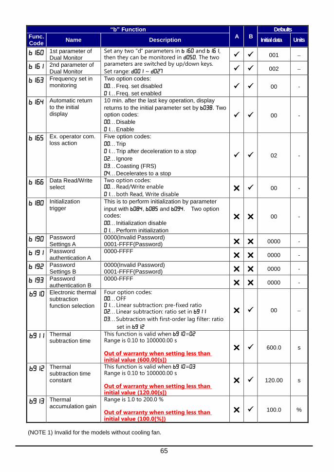
65
“b” Function
A B
Defaults
Func. Code
Name Description Initial data Units
1st parameter of Dual Monitor
Set any two "d" parameters in and , then they can be monitored in . The two parameters are switched by up/down keys.
Set range: ~
001
2nd parameter of Dual Monitor 002
Frequency set in monitoring
Two option codes:
Freq. set disabled
Freq. set enabled 00 -
Automatic return to the initial display
10 min. after the last key operation, display
returns to the initial parameter set by . Two option codes:
Disable
Enable
00 -
Ex. operator com. loss action
Five option codes:
Trip
Trip after deceleration to a stop
Ignore
Coasting (FRS)
Decelerates to a stop
02 -
Data Read/Write select
Two option codes: Read/Write enable
both Read, Write disable 00 -
Initialization trigger
This is to perform initialization by parameter
input with , and . Two option codes:
Initialization disable
Perform initialization
00 -
Password Settings A
0000(Invalid Password) 0001-FFFF(Password) 0000 -
Password authentication A
0000-FFFF 0000 -
Password Settings B
0000(Invalid Password) 0001-FFFF(Password) 0000 -
Password authentication B
0000-FFFF 0000 -
Electronic thermal subtraction function selection
Four option codes: OFF Linear subtraction: pre-fixed ratio Linear subtraction: ratio set in
Subtraction with first-order lag filter: ratio
set in
00
Thermal subtraction time
This function is valid when =Range is 0.10 to 100000.00 s Out of warranty when setting less than initial value (600.00[s])
600.0 s
Thermal subtraction time constant
This function is valid when =Range is 0.10 to 100000.00 s Out of warranty when setting less than initial value (120.00[s])
120.00 s
Thermal accumulation gain
Range is 1.0 to 200.0 % Out of warranty when setting less than initial value (100.0[%])
100.0 %
(NOTE 1) Invalid for the models without cooling fan.

66
Intelligent Terminal Functions
“C” Function
A B
Defaults
Func. Code
Name Description Initial data
Units
Input [1] function Select input terminal [1] function, 56 options (see next section)
00 [FW]
Input [2] function Select input terminal [2] function, 56 options (see next section)
01 [RV]
Input [3] function [GS1 assignable]
Select input terminal [3] function, 56 options (see next section)
12 [EXT]
Input [4] function [GS2 assignable]
Select input terminal [4] function, 56 options (see next section)
18 [RS]
Input [5] function [PTC assignable]
Select input terminal [5] function, 56 options (see next section)
02 [CF1]
Input [6] function Select input terminal [6] function, 56 options (see next section)
03 [CF2]
Input [7] function Select input terminal [7] function, 56 options (see next section)
06 [JG]
Input [1] active state Select logic conversion, two option codes:
normally open [NO]
normally closed [NC]
00
Input [2] active state 00
Input [3] active state 00
Input [4] active state 00
Input [5] active state 00
Input [6] active state 00
Input [7] active state 00
Output [11] function [EDM assignable]
44 programmable functions available for logic (discrete) outputs (see next section)
00
[RUN]
Output [12] function
01
[FA1]
Alarm relay function
05 [AL]
[EO] terminal selection (Pulse/PWM output)
11 programmable functions:
Output frequency (PWM)
Output current (PWM)
Output frequency (Pulse train)
Output voltage (PWM)
Input power (PWM)
Electronic thermal load ratio (PWM)
LAD frequency (PWM)
Output current (Pulse train)
Heat sink temperature (PWM)
General output (PWM)
Option(PWM)
07

67
“C” Function
A B
Defaults
Func. Code
Name Description Initial data
Units
[AM] terminal selection (Analog voltage output
0...10V)
9 programmable functions:
Output frequency
Output current
Output voltage
Input power
Electronic thermal load ratio
LAD frequency
Heat sink temperature
General output
Option
07
[LAD]
Digital current monitor reference value
Current with digital current monitor output at 1,440Hz Range is 20 % to 150 % of rated current
Rated current
A
Output [11] active state Select logic conversion, two option codes:
normally open [NO]
normally closed [NC]
00
Output [12] active state 00 -
Alarm relay active state 01
Output mode of low current detection
Two option codes:
During acceleration, deceleration and constant speed
During constant speed only
01
Low current detection level Set the level of low load detection, range is 0.0 to 1.5 * inverter rated current
Rated
current A
Output mode of overload warning
Two option codes:
During accel., decel. and constant speed
During constant speed only
01
Overload warning level Sets the overload warning signal level between 0% and 200% (from 0 to two time the rated current of the inverter)
Rated current
x 1.15
A
Overload warning level, 2
nd motor
Rated current
x 1.15
A
Frequency arrival setting for acceleration
Sets the frequency arrival setting threshold for the output frequency during acceleration, range is 0.0 to 400.0 Hz
0.0 Hz
Frequency arrival setting for deceleration
Sets the frequency arrival setting threshold for the output frequency during deceleration, range is 0.0 to 400.0 Hz
0.0 Hz
PID deviation level Sets the allowable PID loop error magnitude (absolute value), SP-PV, range is 0.0 to 100 %
3.0 %
Frequency arrival setting 2 for acceleration
Set range is 0.0 to 400.0 Hz 0.00 Hz
Frequency arrival setting 2 for deceleration
Set range is 0.0 to 400.0 Hz 0.00 Hz
PID FBV output high limit
When the PV exceeds this value, the PID loop turns OFF the PID second stage output, range is 0.0 to 100 %
100.0 %
PID FBV output low limit
When the PV goes below this value, the PID loop turns ON the PID second stage output, range is 0.0 to 100 %
0.0 %

68
“C” Function
A B
Defaults
Func. Code
Name Description Initial data
Units
Electronic thermal warning level
Set range is 0 to 100% Setting 0 means disabled. 90. %
Zero speed detection level Set range is 0.00 to 100.0Hz 0.00 Hz
Heat sink overheat warning Set range is 0. to 110. C 100. C
Communication speed Eight option codes:
2,400 bps
4,800 bps
9,600 bps
19,200 bps
38,400 bps
57,600 bps
76,800 bps
115,200 bps
05 baud
Modbus address Set the address of the inverter on the network. Range is 1 to 247 1
Communication parity Three option codes:
No parity
Even parity
Odd parity
00
Communication stop bit Two option codes:
1 bit
2 bit 1 bit
Communication error select Selects inverter response to communications error. Five options:
Trip
Decelerate to a stop and trip
Disable
Free run stop (coasting)
Decelerates to a stop
02
Communication error time-out
Sets the communications watchdog timer period. Range is 0.00 to 99.99 sec 0.0 = disabled
0.00 s
Communication wait time Time the inverter waits after receiving a message before it transmits. Range is 0. to 1000. ms
0. ms
O input span calibration Scale factor between the external frequency command on terminals L–O (voltage input) and the frequency output, range is 0.0 to 200.0%
100.0 %
OI input span calibration Scale factor between the external frequency command on terminals L–OI (voltage input) and the frequency output, range is 0.0 to 200.0%
100.0 %
Thermistor input (PTC) span calibration
Scale factor of PTC input. Range is 0.0 to 200.0%
100.0 %
Debug mode enable Displays debug parameters. Two option codes:
Disable
Enable <Do not set>
(for factory use)
00
Communication selection Modbus-RTU
EzCOM
EzCOM<administrator>
00
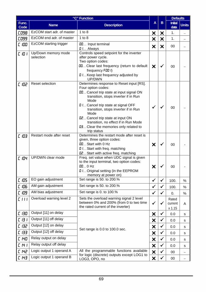
69
“C” Function
A B
Defaults
Func. Code
Name Description Initial data
Units
EzCOM start adr. of master 1 to 8 1.
EzCOM end adr. of master 1 to 8 1.
EzCOM starting trigger Input terminal
Always 00
Up/Down memory mode selection
Controls speed setpoint for the inverter after power cycle. Two option codes:
Clear last frequency (return to default
frequency )
Keep last frequency adjusted by UP/DWN
00
Reset selection Determines response to Reset input [RS]. Four option codes:
Cancel trip state at input signal ON transition, stops inverter if in Run Mode
Cancel trip state at signal OFF transition, stops inverter if in Run Mode
Cancel trip state at input ON transition, no effect if in Run Mode
Clear the memories only related to trip status
00
Restart mode after reset Determines the restart mode after reset is given, three option codes:
Start with 0 Hz
Start with freq. matching
Start with active freq. matching
00 -
UP/DWN clear mode Freq. set value when UDC signal is given to the input terminal, two option codes:
0 Hz
Original setting (in the EEPROM memory at power on)
00 -
EO gain adjustment Set range is 50. to 200.% 100. %
AM gain adjustment Set range is 50. to 200.% 100. %
AM bias adjustment Set range is 0. to 100.% 0. %
Overload warning level 2 Sets the overload warning signal 2 level between 0% and 200% (from 0 to two time the rated current of the inverter)
Rated current
x 1.15
A
Output [11] on delay Set range is 0.0 to 100.0 sec.
0.0 s
Output [11] off delay 0.0 s
Output [12] on delay 0.0 s
Output [12] off delay 0.0 s
Relay output on delay 0.0 s
Relay output off delay 0.0 s
Logic output 1 operand A All the programmable functions available for logic (discrete) outputs except LOG1 to LOG3, OPO, no
00
Logic output 1 operand B 00

70
“C” Function
A B
Defaults
Func. Code
Name Description Initial data
Units
Logic output 1 operator Applies a logic function to calculate [LOG] output state, Three options:
[LOG] = A AND B
[LOG] = A OR B
[LOG] = A XOR B
00
Logic output 2 operand A All the programmable functions available for logic (discrete) outputs except LOG1 to LOG3, OPO, no
00
Logic output 2 operand B 00
Logic output 2 operator Applies a logic function to calculate [LOG] output state, Three options:
[LOG] = A AND B
[LOG] = A OR B
[LOG] = A XOR B
00
Logic output 3 operand A All the programmable functions available for logic (discrete) outputs except LOG1 to LOG3, OPO, no
00
Logic output 3 operand B 00
Logic output 3 operator Applies a logic function to calculate [LOG] output state, Three options:
[LOG] = A AND B
[LOG] = A OR B
[LOG] = A XOR B
00
Input [1] response time Sets response time of each input terminal,
set range is (x 2 [ms]) to (x 2 [ms]) for (0 to 400 [ms]).
1.
Input [2] response time 1.
Input [3] response time 1.
Input [4] response time 1.
Input [5] response time 1.
Input [6] response time 1.
Input [7] response time 1.
Multistage speed/position determination time
Set range is 0. to 200. (x 10ms) 0. ms
Overload warning processing cycle select
Two option codes: 40ms 2ms
00
Overload warning filter time constant
Set the filter time constant for output current detection used for judgement of overload warning. Range is 0 to 9999 ms
0 ms
Overload warning hysteresis
Set the hysteresis for overload warning signal. Range is 0 to 50% of the rated current of the inverter
10.0 %

71
Input Function Summary Table – This table shows all thirty-one intelligent input functions at a glance. Detailed description of these functions, related parameters and settings, and example wiring diagrams are in “Using Intelligent Input Terminals” on page 29.
Input Function Summary Table
Option Code
Terminal Symbol
Function Name Description
FW FORWARD Run/Stop ON Inverter is in Run Mode, motor runs forward
OFF Inverter is in Stop Mode, motor stops
RV Reverse Run/Stop ON Inverter is in Run Mode, motor runs reverse
OFF Inverter is in Stop Mode, motor stops
CF1 Multi-speed Select, Bit 0 (LSB)
ON Binary encoded speed select, Bit 0, logical 1
OFF Binary encoded speed select, Bit 0, logical 0
CF2 Multi-speed Select, Bit 1
ON Binary encoded speed select, Bit 1, logical 1
OFF Binary encoded speed select, Bit 1, logical 0
CF3 Multi-speed Select, Bit 2
ON Binary encoded speed select, Bit 2, logical 1
OFF Binary encoded speed select, Bit 2, logical 0
CF4 Multi-speed Select, Bit 3 (MSB)
ON Binary encoded speed select, Bit 3, logical 1
OFF Binary encoded speed select, Bit 3, logical 0
JG Jogging ON
Inverter is in Run Mode, output to motor runs at jog parameter frequency
OFF Inverter is in Stop Mode
DB External DC braking ON DC braking will be applied during deceleration
OFF DC braking will not be applied
SET Set (select) 2nd Motor Data
ON The inverter uses 2nd motor parameters for generating frequency output to motor
OFF The inverter uses 1st (main) motor parameters for generating frequency output to motor
2CH 2-stage Acceleration and Deceleration
ON Frequency output uses 2nd-stage acceleration and deceleration values
OFF Frequency output uses standard acceleration and deceleration values
FRS Free-run Stop
ON Causes output to turn OFF, allowing motor to free run (coast) to stop
OFF Output operates normally, so controlled deceleration stop motor
EXT External Trip
ON When assigned input transitions OFF to ON, inverter
latches trip event and displays
OFF No trip event for ON to OFF, any recorded trip events remain in history until reset
USP Unattended Start Protection
ON On powerup, the inverter will not resume a Run command (mostly used in the US)
OFF On powerup, the inverter will resume a Run command that was active before power loss
CS Commercial power source switchover
ON Motor can be driven by commercial power
OFF Motor is driven via the inverter
SFT Software Lock ON
The keypad and remote programming devices are prevented from changing parameters
OFF The parameters may be edited and stored
AT Analog Input Voltage/Current Select
ON Refer to “Analog Input Operation” on page 43.
OFF
RS Reset Inverter ON
The trip condition is reset, the motor output is turned OFF, and powerup reset is asserted
OFF Normal power-ON operation
PTC PTC thermistor Thermal Protection (C005 only)
ANLG When a thermistor is connected to terminal [5] and [L], the inverter checks for over-temperature and will cause trip event and turn OFF output to motor
OPEN A disconnect of the thermistor causes a trip event, and the inverter turns OFF the motor
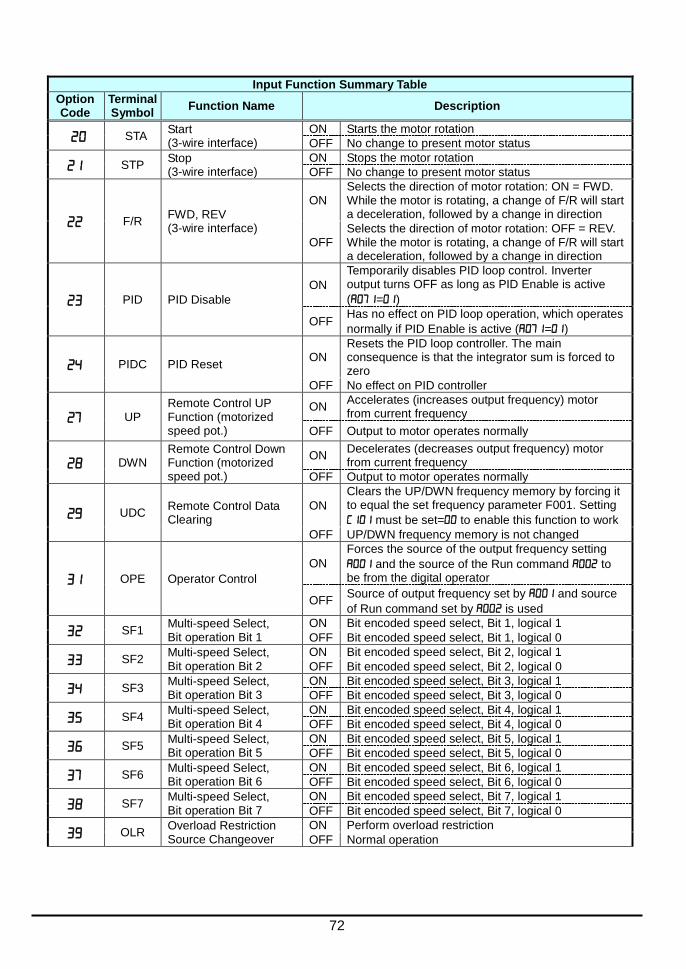
72
Input Function Summary Table
Option Code
Terminal Symbol
Function Name Description
STA Start (3-wire interface)
ON Starts the motor rotation
OFF No change to present motor status
STP Stop (3-wire interface)
ON Stops the motor rotation
OFF No change to present motor status
F/R FWD, REV (3-wire interface)
ON Selects the direction of motor rotation: ON = FWD. While the motor is rotating, a change of F/R will start a deceleration, followed by a change in direction
OFF Selects the direction of motor rotation: OFF = REV. While the motor is rotating, a change of F/R will start a deceleration, followed by a change in direction
PID PID Disable
ON
Temporarily disables PID loop control. Inverter output turns OFF as long as PID Enable is active
(=)
OFF Has no effect on PID loop operation, which operates
normally if PID Enable is active (=)
PIDC PID Reset ON
Resets the PID loop controller. The main consequence is that the integrator sum is forced to zero
OFF No effect on PID controller
UP Remote Control UP Function (motorized speed pot.)
ON Accelerates (increases output frequency) motor from current frequency
OFF Output to motor operates normally
DWN Remote Control Down Function (motorized speed pot.)
ON Decelerates (decreases output frequency) motor from current frequency
OFF Output to motor operates normally
UDC Remote Control Data Clearing
ON
Clears the UP/DWN frequency memory by forcing it to equal the set frequency parameter F001. Setting
must be set= to enable this function to work
OFF UP/DWN frequency memory is not changed
OPE Operator Control
ON
Forces the source of the output frequency setting
and the source of the Run command to be from the digital operator
OFF Source of output frequency set by and source
of Run command set by is used
SF1 Multi-speed Select, Bit operation Bit 1
ON Bit encoded speed select, Bit 1, logical 1
OFF Bit encoded speed select, Bit 1, logical 0
SF2 Multi-speed Select, Bit operation Bit 2
ON Bit encoded speed select, Bit 2, logical 1
OFF Bit encoded speed select, Bit 2, logical 0
SF3 Multi-speed Select, Bit operation Bit 3
ON Bit encoded speed select, Bit 3, logical 1
OFF Bit encoded speed select, Bit 3, logical 0
SF4 Multi-speed Select, Bit operation Bit 4
ON Bit encoded speed select, Bit 4, logical 1
OFF Bit encoded speed select, Bit 4, logical 0
SF5 Multi-speed Select, Bit operation Bit 5
ON Bit encoded speed select, Bit 5, logical 1
OFF Bit encoded speed select, Bit 5, logical 0
SF6 Multi-speed Select, Bit operation Bit 6
ON Bit encoded speed select, Bit 6, logical 1
OFF Bit encoded speed select, Bit 6, logical 0
SF7 Multi-speed Select, Bit operation Bit 7
ON Bit encoded speed select, Bit 7, logical 1
OFF Bit encoded speed select, Bit 7, logical 0
OLR Overload Restriction Source Changeover
ON Perform overload restriction
OFF Normal operation
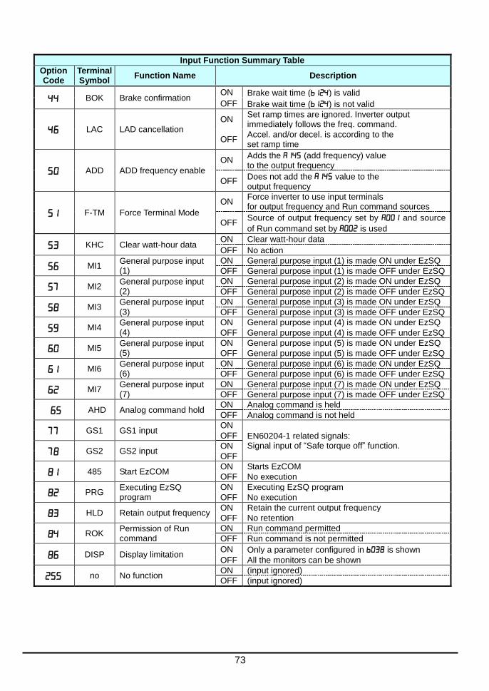
73
Input Function Summary Table
Option Code
Terminal Symbol
Function Name Description
BOK Brake confirmation ON Brake wait time () is valid
OFF Brake wait time () is not valid
LAC LAD cancellation
ON Set ramp times are ignored. Inverter output immediately follows the freq. command.
OFF Accel. and/or decel. is according to the set ramp time
ADD ADD frequency enable
ON Adds the (add frequency) value to the output frequency
OFF Does not add the value to the output frequency
F-TM Force Terminal Mode
ON Force inverter to use input terminals for output frequency and Run command sources
OFF Source of output frequency set by and source
of Run command set by is used
KHC Clear watt-hour data ON Clear watt-hour data
OFF No action
MI1 General purpose input (1)
ON General purpose input (1) is made ON under EzSQ
OFF General purpose input (1) is made OFF under EzSQ
MI2 General purpose input (2)
ON General purpose input (2) is made ON under EzSQ
OFF General purpose input (2) is made OFF under EzSQ
MI3 General purpose input (3)
ON General purpose input (3) is made ON under EzSQ
OFF General purpose input (3) is made OFF under EzSQ
MI4 General purpose input (4)
ON General purpose input (4) is made ON under EzSQ
OFF General purpose input (4) is made OFF under EzSQ
MI5 General purpose input (5)
ON General purpose input (5) is made ON under EzSQ
OFF General purpose input (5) is made OFF under EzSQ
MI6 General purpose input (6)
ON General purpose input (6) is made ON under EzSQ
OFF General purpose input (6) is made OFF under EzSQ
MI7 General purpose input (7)
ON General purpose input (7) is made ON under EzSQ
OFF General purpose input (7) is made OFF under EzSQ
AHD Analog command hold ON Analog command is held
OFF Analog command is not held
GS1 GS1 input ON
EN60204-1 related signals: Signal input of “Safe torque off” function.
OFF
GS2 GS2 input ON
OFF
485 Start EzCOM ON Starts EzCOM
OFF No execution
PRG Executing EzSQ program
ON Executing EzSQ program
OFF No execution
HLD Retain output frequency ON Retain the current output frequency
OFF No retention
ROK Permission of Run command
ON Run command permitted
OFF Run command is not permitted
DISP Display limitation ON Only a parameter configured in is shown
OFF All the monitors can be shown
no No function ON (input ignored)
OFF (input ignored)
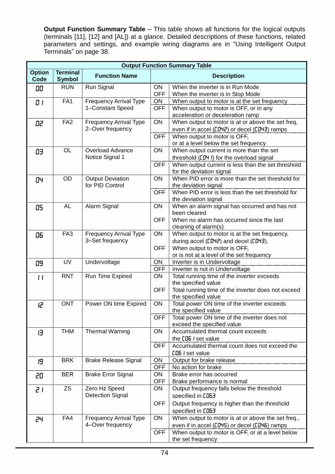
74
Output Function Summary Table – This table shows all functions for the logical outputs (terminals [11], [12] and [AL]) at a glance. Detailed descriptions of these functions, related parameters and settings, and example wiring diagrams are in “Using Intelligent Output Terminals” on page 38.
Output Function Summary Table
Option Code
Terminal Symbol
Function Name Description
RUN Run Signal ON When the inverter is in Run Mode
OFF When the inverter is in Stop Mode
FA1 Frequency Arrival Type 1–Constant Speed
ON When output to motor is at the set frequency
OFF When output to motor is OFF, or in any acceleration or deceleration ramp
FA2 Frequency Arrival Type 2–Over frequency
ON When output to motor is at or above the set freq,
even if in accel () or decel () ramps
OFF When output to motor is OFF, or at a level below the set frequency
OL Overload Advance Notice Signal 1
ON When output current is more than the set
threshold () for the overload signal
OFF When output current is less than the set threshold for the deviation signal
OD Output Deviation for PID Control
ON When PID error is more than the set threshold for the deviation signal
OFF When PID error is less than the set threshold for the deviation signal
AL Alarm Signal ON When an alarm signal has occurred and has not been cleared
OFF When no alarm has occurred since the last cleaning of alarm(s)
FA3 Frequency Arrival Type 3–Set frequency
ON When output to motor is at the set frequency,
during accel () and decel ().
OFF When output to motor is OFF, or is not at a level of the set frequency
UV Undervoltage ON Inverter is in Undervoltage
OFF Inverter is not in Undervoltage
RNT Run Time Expired ON Total running time of the inverter exceeds the specified value
OFF Total running time of the inverter does not exceed the specified value
ONT Power ON time Expired ON Total power ON time of the inverter exceeds the specified value
OFF Total power ON time of the inverter does not exceed the specified value
THM Thermal Warning ON Accumulated thermal count exceeds
the set value
OFF Accumulated thermal count does not exceed the
set value
BRK Brake Release Signal ON Output for brake release
OFF No action for brake
BER Brake Error Signal ON Brake error has occurred
OFF Brake performance is normal
ZS Zero Hz Speed Detection Signal
ON Output frequency falls below the threshold
specified in
OFF Output frequency is higher than the threshold
specified in
FA4 Frequency Arrival Type 4–Over frequency
ON When output to motor is at or above the set freq.,
even if in accel () or decel () ramps
OFF When output to motor is OFF, or at a level below the set frequency
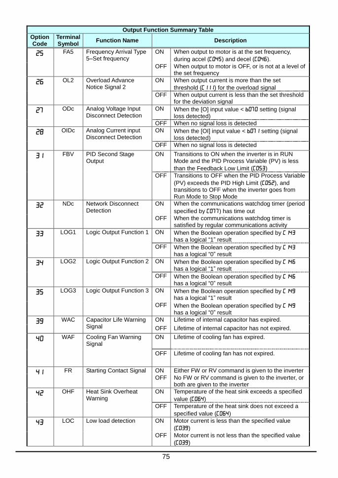
75
Output Function Summary Table
Option Code
Terminal Symbol
Function Name Description
FA5 Frequency Arrival Type 5–Set frequency
ON When output to motor is at the set frequency,
during accel () and decel ().
OFF When output to motor is OFF, or is not at a level of the set frequency
OL2 Overload Advance Notice Signal 2
ON When output current is more than the set
threshold () for the overload signal
OFF When output current is less than the set threshold for the deviation signal
ODc Analog Voltage Input Disconnect Detection
ON When the [O] input value < setting (signal loss detected)
OFF When no signal loss is detected
OIDc Analog Current input Disconnect Detection
ON When the [OI] input value < setting (signal loss detected)
OFF When no signal loss is detected
FBV PID Second Stage Output
ON Transitions to ON when the inverter is in RUN Mode and the PID Process Variable (PV) is less
than the Feedback Low Limit ()
OFF Transitions to OFF when the PID Process Variable
(PV) exceeds the PID High Limit (), and transitions to OFF when the inverter goes from Run Mode to Stop Mode
NDc Network Disconnect Detection
ON When the communications watchdog timer (period
specified by ) has time out
OFF When the communications watchdog timer is satisfied by regular communications activity
LOG1 Logic Output Function 1 ON When the Boolean operation specified by has a logical “1” result
OFF When the Boolean operation specified by has a logical “0” result
LOG2 Logic Output Function 2 ON When the Boolean operation specified by has a logical “1” result
OFF When the Boolean operation specified by has a logical “0” result
LOG3 Logic Output Function 3 ON When the Boolean operation specified by has a logical “1” result
OFF When the Boolean operation specified by has a logical “0” result
WAC Capacitor Life Warning Signal
ON Lifetime of internal capacitor has expired.
OFF Lifetime of internal capacitor has not expired.
WAF Cooling Fan Warning Signal
ON Lifetime of cooling fan has expired.
OFF Lifetime of cooling fan has not expired.
FR Starting Contact Signal ON Either FW or RV command is given to the inverter
OFF No FW or RV command is given to the inverter, or both are given to the inverter
OHF Heat Sink Overheat Warning
ON Temperature of the heat sink exceeds a specified
value ()
OFF Temperature of the heat sink does not exceed a
specified value ()
LOC Low load detection ON Motor current is less than the specified value
()
OFF Motor current is not less than the specified value
()

76
Output Function Summary Table
Option Code
Terminal Symbol
Function Name Description
MO1 General Output 1 ON General output 1 is ON
OFF General output 1 is OFF
MO2 General Output 2 ON General output 2 is ON
OFF General output 2 is OFF
MO3 General Output 3 ON General output 3 is ON
OFF General output 3 is OFF
IRDY Inverter Ready Signal ON Inverter can receive a run command
OFF Inverter cannot receive a run command
FWR Forward Rotation ON Inverter is driving the motor in forward direction
OFF Inverter is not driving the motor in forward direction
RVR Reverse Rotation ON Inverter is driving the motor in reverse direction
OFF Inverter is not driving the motor in reverse direction
MJA Major Failure Signal ON Inverter is tripping with major failure
OFF Inverter is normal, or is not tripping with major failure
WCO Window Comparator for Analog Voltage Input
ON Analog voltage input value is inside of the window comparator
OFF Analog voltage input value is outside of the window comparator
WCOI Window Comparator for Analog Current Input
ON Analog current input value is inside of the window comparator
OFF Analog current input value is outside of the window comparator
FREF Frequency Command Source
ON Frequency command is given from the operator
OFF Frequency command is not given from the operator
REF Run Command Source ON Run command is given from the operator
OFF Run command is not given from the operator
SETM 2nd
Motor Selection ON 2nd
motor is being selected
OFF 2nd
motor is not being selected
EDM STO (Safe Torque Off) Performance Monitor (Output terminal 11 only)
ON STO is being performed
OFF STO is not being performed
OPO Option card output ON (output terminal for option card)
OFF (output terminal for option card)
no Not used ON -
OFF -

77
Motor Constants Functions
“H” Function
A B
Defaults
Func. Code
Name Description Initial data Units
Motor capacity Twelve selections: 0.1/0.2/0.4/0.75/1.5/2.2/3.7/5.5/7.5/11/15/18.5
Specified by the capacity
of each inverter model
kW
Motor capacity, 2
nd motor kW
Motor poles setting
Twenty four selections: 2/4/6/8/10/12/14/16/18/20/22/24/26/28/30/32/ 34/36/38/40/42/44/46/48
4 poles
Motor poles setting, 2
nd motor
4 poles
Motor stabilization constant
Motor constant (factory set), range is 0. to 255. 100..
Motor stabilization constant, 2
nd motor
100.
Expansion Card Functions “P” parameters will be appeared when the expansion option is connected.
“P” Function
A B
Defaults
Func. Code
Name Description Initial data Units
Reaction when option card error occurs
Two option codes:
…Inverter trips
…Ignores the error (Inverter continues operation)
00 -
Deceleration time Input Type
…Operator
…EzSQ 00 -
Communication watchdog timer (for option)
Set range is 0.00 to 99.99s 1.00 s
Inverter action on communication error (for option)
…Tripping
…Tripping after decelerating and stopping the motor
…Ignoring errors
…Stopping the motor after free-running
…Decelerating and stopping the motor
00 -
DeviceNet polled I/O: Output instance number
0 to 20
01 -
Inverter action on communication idle mode
…Tripping
…Tripping after decelerating and stopping the motor
…Ignoring errors
…Stopping the motor after free-running
…Decelerating and stopping the motor
00 -
Motor poles setting for RPM
0/2/4/6/8/10/12/14/16/18/20/22/24/ 26/28/30/32/34/36/38/40/42/44/46/48 0 Poles

78
“P” Function
A B
Defaults
Func. Code
Name Description Initial data Units
to
EzSQ user parameter U(00) ~ U(31)
Each set range is 0 to 65535
0 -
EzCOM number of data
1 to 5 5 -
EzCOM destination 1 address
1 to 247 1 -
EzCOM destination 1 register
0000 to FFFF 0000 -
EzCOM source 1 register
0000 to FFFF 0000 -
EzCOM destination 2 address
1 to 247 2 -
EzCOM destination 2 register
0000 to FFFF 0000 -
EzCOM source 2 register
0000 to FFFF 0000 -
EzCOM destination 3 address
1 to 247 3 -
EzCOM destination 3 register
0000 to FFFF 0000 -
EzCOM source 3 register
0000 to FFFF 0000 -
EzCOM destination 4 address
1 to 247 4 -
EzCOM destination 4 register
0000 to FFFF 0000 -
EzCOM source 4 register
0000 to FFFF 0000 -
EzCOM destination 5 address
1 to 247 5 -
EzCOM destination 5 register
0000 to FFFF 0000 -
EzCOM source 5 register
0000 to FFFF 0000 -
to
Option I/F command register to write 1 to 10
0000h to FFFFh 0000 -
to
Option I/F command register to read 1 to 10
0000h to FFFFh 0000 -
Profibus Node address
0. to 125. 0. -
Profibus Clear Node address
…Clear …Hold previous time value 00 -
Profibus Map selection
…PPO type …Conventional …Flexible Mode Format Selection
00 -
DeviceNet MAC ID 0 to 63 63 -

79
User setting parameters
“U” Function
A B
Defaults
Func. Code
Name Description Initial data Units
to
User parameters 1
to 32
no/d001 to P196 Set range,
“", -

80
Monitoring Trip Events, History, & Conditions
Trip History and Inverter Status
We recommend that you first find the cause of the fault before clearing it. When a fault occurs, the inverter stores the important performance data at the moment of the fault. To access the
data, use the monitor function (xxx) and select details about the present fault. The
previous 5 faults are stored in to . When a fault occurs, each error log shifts
- to -, and the latest error log is written in .
The following Monitor Menu map shows how to access the error logs. When fault(s) exist,
you can review their details by first selecting the proper function: is the most recent,
and is the oldest.
SET ESC
Trip history 1 (Latest)
Error code
Hz
A
Hz
A
Hz
A
Hz
A
Hz
A
Hz
A
. . .
Trip history 6
.
.
.
.
Output frequency
Output current
DC bus voltage
Elapsed RUN time
Elapsed power-
ON time
Trip cause Inverter status at trip point
.
Note: Indicated inverter status could be different from actual inverter behavior. e.g. When PID operation or frequency given by analog signal, although it seems constant speed, acceleration and deceleration could be repeated in very short cycle.
.
.
.
.
.
.
.
.
.
Power up or initial processing
Stop
Deceleration
Constant speed
Acceleration
0Hz command and RUN
Starting
DC braking
Overload restriction

81
Error Codes
An error code will appear on the display automatically when a fault causes the inverter to trip. The following table lists the cause associated with the error.
Error Code
Name Cause(s)
Over-current event while at constant speed
The inverter output was short-circuited, or the motor shaft is locked or has a heavy load. These conditions cause excessive current for the inverter, so the inverter output is turned OFF. Setting in dual-voltage motor is wrong.
Over-current event during deceleration
Over-current event during acceleration
Over-current event during other conditions
Overload protection When a motor overload is detected by the electronic thermal function, the inverter trips and turns OFF its output.
Braking resistor overload protection When the BRD operation rate exceeds the setting of "b090", this protective function shuts off the inverter output and displays the error code.
Over-voltage protection When the DC bus voltage exceeds a threshold, due to such causes as regenerative energy from the motor or rise of power voltage, etc.
EEPROM error When the built-in EEPROM memory has problems due to noise or excessive temperature, the inverter trips and turns OFF its output to the motor.
Under-voltage error A decrease of internal DC bus voltage below a threshold results in a control circuit fault. This condition can also generate excessive motor heat or cause low torque. The inverter trips and turns OFF its output.
Current detection error If an error occurs in the internal current detection system, the inverter will shut off its output and display the error code.
CPU error A malfunction in the built-in CPU has occurred, so the inverter trips and turns OFF its output to the motor.
External trip A signal on an intelligent input terminal configured as EXT has occurred. The inverter trips and turns OFF the output to the motor.
USP When the Unattended Start Protection (USP) is enabled, an error occurred when power is applied while a Run signal is present. The inverter trips and does not go into Run Mode until the error is cleared.
Ground fault The inverter is protected by the detection of ground faults between the inverter output and the motor upon during powerup tests. This feature protects the inverter, and does not protect humans.
Input over-voltage The inverter tests for input over-voltage after the inverter has been in Stop Mode for 100 seconds. If an over-voltage condition exists, the inverter enters a fault state. After the fault is cleared, the inverter can enter Run Mode again.
Inverter thermal detection system error
When the thermal sensor in the inverter module is not connected.
Inverter thermal trip When the inverter internal temperature is above the threshold, the thermal sensor in the inverter module detects the excessive temperature of the power devices and trips, turning the inverter output OFF.
CPU communication error When communication between two CPU fails, inverter trips and displays the error code.

82
Error Code
Name Cause(s)
Main circuit error
The inverter will trip if the power supply establishment is not recognized because of a malfunction due to noise or damage to the main circuit element.
Driver error An internal inverter error has occurred at the safety protection circuit between the CPU and main driver unit. Excessive electrical noise may be the cause. The inverter has turned OFF the IGBT module output.
Thermistor When a thermistor is connected to terminals [5] and [L] and the inverter has sensed the temperature is too high, the inverter trips and turns OFF the output.
Braking error When "01" has been specified for the Brake Control Enable (b120), the inverter will trip if it cannot receive the braking confirmation signal within the Brake Wait Time for Confirmation (b124) after the output of the brake release signal.
Safe Stop Safe stop signal is given when b145 =01.
Low-speed overload protection If overload occurs during the motor operation at a very low speed, the inverter will detect the overload and shut off the inverter output.
Operator connection When the connection between inverter and operator keypad failed, inverter trips and displays the error code.
Modbus communication error When “trip” is selected (C076=00) as a behavior in case of communication error, inverter trips when timeout happens.
EzSQ invalid instruction The program stored in inverter memory has been destroyed, or the PRG terminal was turned on without a program downloaded to the inverter.
EzSQ nesting count error Subroutines, if-statement, or for-next loop are nested in more than eight layers
EzSQ instruction error Inverter found the command which cannot be executed.
to
EzSQ user trip (0 to 9) When user –defined trip happens, inverter trips and displays the error code.
to
Option error The inverter detects errors in the option board mounted in the optional slot. For details, refer to the instruction manual for the mounted option board.
NOTE: Reset is not allowed in 10 second after trip.
NOTE: When error E08, E14 and E30 occur, reset operation by RS terminal or STOP/RESET key is
not accepted. In this case, reset by cycling power. If still same error occurs, perform initialization.
NOTE: When error E37 occur, reset operation by STOP/RESET key is not accepted. In this case,
reset by cycling power. If still same error occurs, perform initialization.
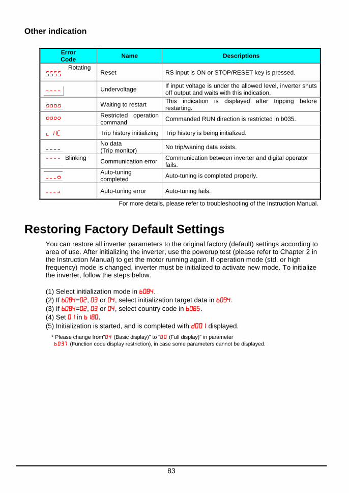
83
Other indication
Error Code
Name Descriptions
RotatingReset RS input is ON or STOP/RESET key is pressed.
Undervoltage If input voltage is under the allowed level, inverter shuts off output and waits with this indication.
Waiting to restart This indication is displayed after tripping before restarting.
Restricted operation command
Commanded RUN direction is restricted in b035.
Trip history initializing Trip history is being initialized.
No data (Trip monitor)
No trip/waning data exists.
BlinkingCommunication error
Communication between inverter and digital operator fails.
Auto-tuning completed
Auto-tuning is completed properly.
Auto-tuning error Auto-tuning fails.
For more details, please refer to troubleshooting of the Instruction Manual.
Restoring Factory Default Settings You can restore all inverter parameters to the original factory (default) settings according to area of use. After initializing the inverter, use the powerup test (please refer to Chapter 2 in the Instruction Manual) to get the motor running again. If operation mode (std. or high frequency) mode is changed, inverter must be initialized to activate new mode. To initialize the inverter, follow the steps below.
(1) Select initialization mode in .
(2) If =, or , select initialization target data in .
(3) If =, or , select country code in .
(4) Set in .
(5) Initialization is started, and is completed with displayed.
* Please change from" (Basic display)" to " (Full display)" in parameter
(Function code display restriction), in case some parameters cannot be displayed.

84
CE-EMC Installation Guidelines You are required to satisfy the EMC directive (2004/108/EC) when using a WL200 inverter in an EU country.
To satisfy the EMC directive and to comply with standard, you need to use a dedicated EMC filter suitable for each model, and follow the guidelines in this section. Following table shows the compliance condition for reference.
Table 1. Condition for the compliance
Model Cat. Carrier f Motor cable
All WL200 series C1 2kHz 20m (Shielded)
Table 2. Applicable EMC filter
Input class Inverter model Filter model (Schaffner)
1-ph. 200V class
WL200-002SF
FS24828-8-07 WL200-004SF
WL200-007SF
WL200-015SF FS24828-27-07
WL200-022SF
3-ph. 400V class
WL200-004HF FS24830-6-07 WL200-007HF
WL200-015HF
WL200-022HF
FS24830-12-07 WL200-030HF
WL200-040HF
WL200-055HF FS24830-15-07
WL200-075HF FS24830-29-07
WL200-110HF
WL200-150HF FS24830-48-07
WL200-185HF
WL200-185H needs to be installed in a metal cabinet and add ferrite core at the input cable to meet category C1. Unless otherwise category C2.
Important notes
1. Input choke or other equipment is required if necessary to comply with EMC directive from the harmonic distortion point of view (IEC 61000-3-2 and 4).
2. If the motor cable length exceeds 20m, use output choke to avoid unexpected problem due to the leakage current from the motor cable (such as malfunction of the thermal relay, vibration of the motor, etc...).
3. As user you must ensure that the HF (high frequency) impedance between adjustable frequency inverter, filter, and ground is as small as possible.
Ensure that the connections are metallic and have the largest possible contact areas (zinc-plated mounting plates).
4. Avoid conductor loops that act like antennas, especially loops that encompass large areas.
Avoid unnecessary conductor loops.
Avoid parallel arrangement of low-level signal wiring and power-carrying or noise-prone conductors.
5. Use shielded wiring for the motor cable and all analog and digital control lines.
Allow the effective shield area of these lines to remain as large as possible; i.e., do not strip away the shield (screen) further away from the cable end than absolutely necessary.

85
With integrated systems (for example, when the adjustable frequency inverter is communicating with some type of supervisory controller or host computer in the same control cabinet and they are connected at the same protective ground), connect the shields of the control lines to protective ground at both ends. With distributed systems (for example the communicating supervisory controller or host computer is not in the same control cabinet and there is a distance between the systems), we recommend connecting the shield of the control lines only at the end connecting to the adjustable frequency inverter. If possible, route the other end of the control lines directly to the cable entry section of the supervisory controller or host computer. The shield conductor of the motor cables must always be connected to protective ground at both ends.
To achieve a large area contact between shield and protective ground, use a PG screw with a metallic shell, or use a metallic mounting clip.
Use only cable with braided, tinned copper mesh shield (type “CY”) with 85% coverage.
The shielding continuity should not be broken at any point in the cable. If the use of reactors, contactors, terminals, or safety switches in the motor output is necessary, the unshielded section should be kept as short as possible.
Some motors have a rubber gasket between terminal box and motor housing. Very often, the terminal boxes, and particularly the threads for the metal PG screw connections, are painted. Make sure there is always a good metallic connection between the shielding of the motor cable, the metal PG screw connection, the terminal box, and the motor housing. If necessary, carefully remove paint between conducting surfaces.
6. Take measures to minimize interference that is frequently coupled in through installation cables.
Separate interfering cables with 0.25m minimum from cables susceptible to interference. A particularly critical point is laying parallel cables over longer distances. If two cables intersect (one crosses over the other), the interference is smallest if they intersect at an angle of 90°. Cables susceptible to interference should therefore only intersect motor cables, intermediate circuit cables, or the wiring of a rheostat at right angles and never be laid parallel to them over longer distances.
7. Minimize the distance between an interference source and an interference sink (interference- threatened device), thereby decreasing the effect of the emitted interference on the interference sink.
You should use only interference-free devices and maintain a minimum distance of 0.25 m from the adjustable frequency inverter.
8. Follow safety measures in the filter installation.
If using external EMC filter, ensure that the ground terminal (PE) of the filter is properly connected to the ground terminal of the adjustable frequency inverter. An HF ground connection via metal contact between the housings of the filter and the adjustable frequency inverter, or solely via cable shield, is not permitted as a protective conductor connection. The filter must be solidly and permanently connected with the ground potential so as to preclude the danger of electric shock upon touching the filter if a fault occurs.
To achieve a protective ground connection for the filter:
Ground the filter with a conductor of at least 10 mm2 cross-sectional area.
Connect a second grounding conductor, using a separate grounding terminal parallel to the protective conductor. (The cross section of each single protective conductor terminal must be sized for the required nominal load.)

86
Installation for WL200 series (example of SF models)
HFx (3-ph. 400V class) Models are the same concept for the installation.
*) Both earth portions of the shielded cable must be connected to the earth point by cable clamps.
Input choke or equipment to reduce harmonic current is necessary for CE marking (IEC 61000-3-2 and IEC61000-3-3) from the harmonic current point of view, even conducted emission and radiated emission passed without the input choke.
Shielded cable
Power supply
1-ph. 200V
M
U,V,W
Metal plate (earth)
Earth line is connected to the heatsink of the inverter (or PE terminal for bigger models)
PE
EMC filter
(Foot-print)
Cable clamp *
The filter is a footprint type, so it is located between the inverter and the metal plate.
Remove the insulation material coating of the earth contact portions so to obtain good grounding condition.
Cable clamp *
Metal plate (earth)
L1,N

87
Hitachi EMC Recommendations
WARNING: This equipment should be installed, adjusted, and serviced by qualified personnel familiar with construction and operation of the equipment and the hazards involved. Failure to observe this precaution could result in bodily injury.
Use the following checklist to ensure the inverter is within proper operating ranges and conditions.
1. The power supply to WL200 inverters must meet these specifications:
Voltage fluctuation ±10% or less
Voltage imbalance ±3% or less
Frequency variation ±4% or less
Voltage distortion THD = 10% or less
2. Installation measure:
Use a filter designed for WL200 inverter. Refer to the instruction of the applicable external EMC filter.
3. Wiring:
Shielded wire (screened cable) is required for motor wiring, and the length must be 20 meter or less.
If the motor cable length exceeds the value shown above, use output choke to avoid unexpected problem due to the leakage current from the motor cable.
The carrier frequency setting must be 2 kHz to satisfy EMC requirements.
Separate the power input and motor wiring from the signal/process circuit wiring.
4. Environmental conditions—when using a filter, follow these guidelines:
Ambient temperature: –10 to 40°C (Derating is required when the ambient temperature exceeds 40 °C)
Humidity: 20 to 90% RH (non-condensing)
Vibration: 5.9 m/sec2 (0.6 G) 10 ~ 55Hz
Location: 1000 meters or less altitude, indoors (no corrosive gas or dust)
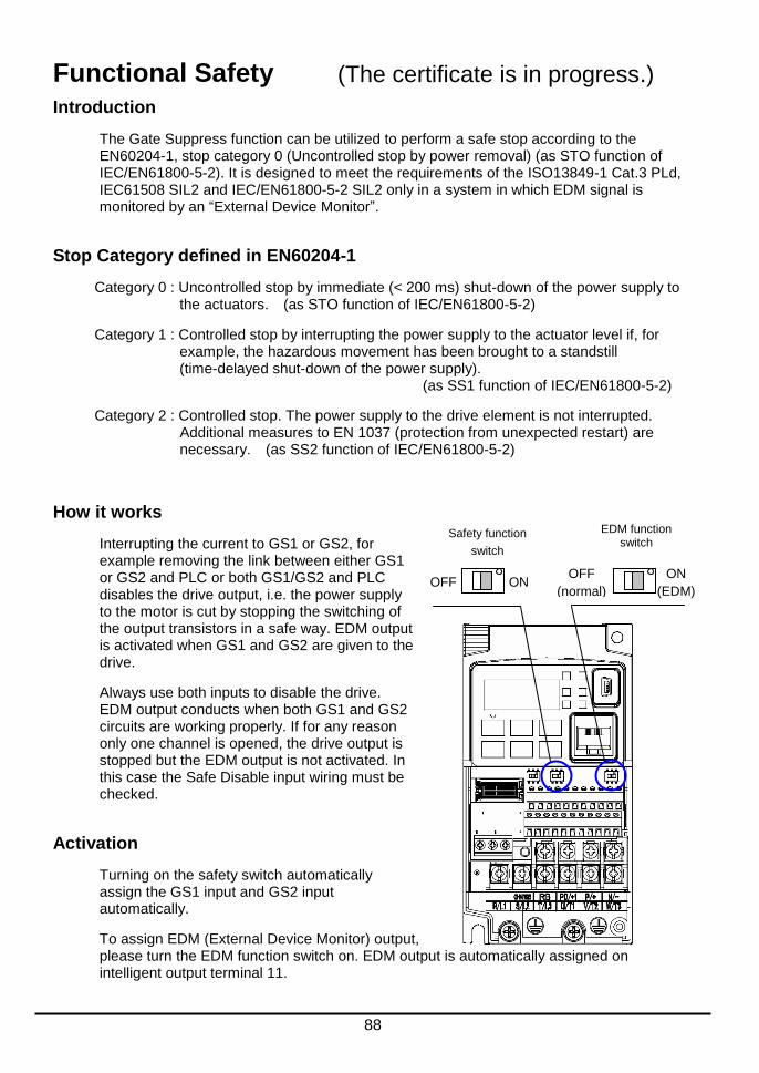
88
Functional Safety
Introduction
The Gate Suppress function can be utilized to perform a safe stop according to the EN60204-1, stop category 0 (Uncontrolled stop by power removal) (as STO function of IEC/EN61800-5-2). It is designed to meet the requirements of the ISO13849-1 Cat.3 PLd, IEC61508 SIL2 and IEC/EN61800-5-2 SIL2 only in a system in which EDM signal is monitored by an “External Device Monitor”.
Stop Category defined in EN60204-1
Category 0 : Uncontrolled stop by immediate (< 200 ms) shut-down of the power supply to the actuators. (as STO function of IEC/EN61800-5-2)
Category 1 : Controlled stop by interrupting the power supply to the actuator level if, for example, the hazardous movement has been brought to a standstill (time-delayed shut-down of the power supply). (as SS1 function of IEC/EN61800-5-2)
Category 2 : Controlled stop. The power supply to the drive element is not interrupted. Additional measures to EN 1037 (protection from unexpected restart) are necessary. (as SS2 function of IEC/EN61800-5-2)
How it works
Interrupting the current to GS1 or GS2, for example removing the link between either GS1 or GS2 and PLC or both GS1/GS2 and PLC disables the drive output, i.e. the power supply to the motor is cut by stopping the switching of the output transistors in a safe way. EDM output is activated when GS1 and GS2 are given to the drive.
Always use both inputs to disable the drive. EDM output conducts when both GS1 and GS2 circuits are working properly. If for any reason only one channel is opened, the drive output is stopped but the EDM output is not activated. In this case the Safe Disable input wiring must be checked.
Activation
Turning on the safety switch automatically assign the GS1 input and GS2 input automatically.
To assign EDM (External Device Monitor) output, please turn the EDM function switch on. EDM output is automatically assigned on intelligent output terminal 11.
Safety function
switch
EDM function switch
ON OFF ON
(EDM)
OFF
(normal)
(The certificate is in progress.)

89
(When safety switch or EDM switch is turned off, the intelligent input and output terminal assigned on will be set as "no" function, and contact will remain normally off.)
Always use both inputs to disable the drive. If for any reason only one channel is opened, the drive output is stopped but the EDM output is not activated. In this case the Safe Disable input wiring must be checked.
Installation
According to the safety standard listed above, please install referring to the example. Please be sure to use the both GS1 and GS2, and construct the system that GS1 andGS2 are both turned off when safety input is given to the inverter.
Be sure to carry out the proof test when installation is ready before operation.
When the Gate Suppress function is utilized, connect the drive to a safety certified interrupting device utilizing EDM output signal to reconfirm both safety inputs GS1 and GS2. Follow the wiring instructions in the Instruction manual.
Note 1) They are automatically set when safety switch is turned ON, cannot be changed.
Note 2) Those are automatically assigned when EDM switch is turned ON, cannot be changed.
Note 3) Inverter trips with "E37". When competing with external trip (E12), E37 has priority.
Note 4) While the drive is the trip status "E037" and either GS1 or GS2 is activated, on the safety by is not guaranteed.
item Function
code data description
Input [3] and [4] function
C003 77 GS1: Safety input 1 (note 1)
C004 78 GS2:Safety input 2 (note 1)
Input [3] and [4] active state
C013 01 NC: Normally Closed (note 1)
C014 01 NC: Normally Closed (note 1)
Output [11] function C021 62 EDM:External Device Monitor(note2)
Output [11] active state
C031 00 NO: Normally Open (note 2)
GS input mode b145
00 Output is shut off by hardware. No trip.
01 Output is shut off by hardware, and then, trip. (note3) (note4)

90
Wiring example
When the Gate Suppress function is utilized, connect the drive to a safety certified interrupting device utilizing EDM output signal to reconfirm both safety inputs GS1 and GS2. Follow the wiring instructions in the Instruction manual.
Any external signal voltage connected to the WL200 must be from a SELV Power Supply.
By pressing the emergency stop button, the current to GS1 and GS2 is shut off, and the inverter output is shut off. By this, motor is free-running. This behavior is according to the stop category 0 defined in EN60204.
Note 1: Above is the example to use the intelligent input terminal with source logic. When it is used with sink logic, the wiring is to be modified.
Note 2: The wire for safety relay and emergency input signal are to be shielded coaxial cable for example RS174/U (produced by LAPP) by MIL-C17, or KX2B by NF C 93-550 with diameter 2.9mm with less than 2 meters. Please be sure to ground the shielding.
Note 3: All the inductance related parts such as relay and contactor are required to contain the over-voltage protection circuit.
Fuse *
(*) Specification of the fuse:
The arch extinguishing fuse with rated voltage AC250V, rated current 100mA complies to either IEC6127 -2/-3/-4
example) SOC EQ series AC250V, 100mA (UL, SEMKO, BSI)
Little 216 series AC250V, 100mA (CCC, UL, CSA, SEMKO, CE, VDE)
EDM (feedback) input
WL200
Safety output
Safety Unit
※Standard
(IEC61508, ISO13849) certified
KM1
M
Reset Switch
GS2
GS1
EDM
CM2
Safety input
S14
S24
T12
T21
T22
A1
A2
Safety Switch (Example: emergency
push button)
T11 T31 T32
PLC
L
+24V
T33
+24V

91
Inverter doesn’t block the current flowing into itself when it is not powered. This may cause the closed circuit when two or more inverters are connected to common I/O wiring as shown below to result in unexpected turning the on the input. This may lead to dangerous situation. To avoid this closed circuit, please put the diode (rated:50V/0.1A) in the path as described below.
IF the protection diodes used when the units are in wired parallel are only single diodes then their condition would be checked as part of the proof test.
By having ability inverter doesn’t block the current flowing into itself when it is not powered. This may cause the closed circuit when two or more inverters are connected to common I/O wiring as shown below to result in unexpected turning the on the input. To avoid this closed circuit, please put the diode (rated:50V/0.1A) in the path as described below.
In case of Sink logic
In case of Source logic
Power ON Power ON Jumper
wire
Inserting
diode
P24
PLC
L
1
P24
PLC
L
1
Switch OFF
Power OFF
Input
ON
P24
PLC
L
1
P24
PLC
L
1
Switch OFF
Power OFF
Input
OFF
Jumper
wire
1
Switch OFF
Switch OFF
Input OFF
Input ON
P24
PLC
L
P24
PLC
L
P24
PLC
L
P24
PLC
L
1
1 1
Jumper
wire
Jumper
wire
The current loop cause turn the input ON even the switch is off when diode is not inserted.
The current loop is to be prevented by inserting diode instead of short bar.

92
Components to be combined
Followings are the example of the safety devices to be combined.
Series Model Norms to comply Certification date
GS9A 301 ISO13849-2 cat4, SIL3 06.06.2007
G9SX GS226-T15-RC IEC61508 SIL1-3 04.11.2004
NE1A SCPU01-V1 IEC61508 SIL3 27.09.2006
The configuration of and components used in any circuit other than an appropriately pre approved safety module that interfaces with the WL200 GS1/GS2 and EDM ports MUST be at least equivalent to Cat.3 PLd under ISO 13849-1:2006 in order to be able to claim an overall Cat.3 PLd for the WL200 and external circuit combination.
The EMI level that the external module has been assessed to must be at least equivalent to that of Annex E in IEC 62061.
Periodical check (proof test)
Proof test is essential to be able to reveal any dangerous undetected failures after a period of time, in this case 1 year. Carrying out this proof test at least one a year is the condition to comply the ISO13849-1 PLd.
Terminal Status
GS1 current OFF current ON current OFF current ON
GS2 current OFF current OFF current ON current ON
EDM conducted not conducted not conducted not conducted
(output) forbidden forbidden forbidden Allowed
- To activate (give current to) GS1 and GS2 simultaneously and separately to see output is allowed and EDM is conducting
- To activate (give current to) both GS1 and GS2 to see output is allowed and EDM is not conducting
- To activate (give current to) GS1, not to activate GS2 and see output is forbidden and EDM is not conducting
- To activate (give current to) GS2, not to activate GS1 and see output is forbidden and EDM is not conducting
- To deactivate (interrupt current to) both GS1 and GS2 to see output is forbidden and EDM is conducting
Be sure to carry out the proof test when installation is ready before operation.
IF the protection diodes used when the units are in wired parallel are only single diodes then their condition would be checked as part of the proof test. Check to reconfirm the diodes are not damaged when proof test is done.
Precautions
1. To assure, that the Safe Disable function appropriately fulfills the safety requirements of the application, a throughout risk assessment for the whole safety system has to be carried out.
2. The Safe Disable function does not cut the power supply to the drive and does not provide electrical isolation. Before any installation or maintenance work is done, the drives power supply must be switched off and place a tag/lock-out.
3. The wiring distance for the Safe Disable inputs should be shorter than 30 m.
4. The time from opening the Safe Disable input until the drive output is switched off is less than 10 ms.