kuhnke technical data magnet: ca. 32 g anker: ca. 8 g standard: spannung: 24 v dc litze: 10 cm...
TRANSCRIPT

Kuhnke Technical Data
The following page(s) are extracted from multi-page Kuhnke product catalogues or CDROMs and any page number shown is relevant to the original document. The PDF sheets here may have been combined to provide technical information about the specific product(s) you have selected. Hard copy product catalogues, and CDROMs have been published describing Kuhnke Pneumatics, Solenoids, Relays and Electronics; some divided into different books. A list of current publications is available on this web site or from our sales offices. Some may be available for download, but as substantially larger files. Contact Details
Kuhnke sales and service in the UK H. Kuhnke Ltd Unit 6 Focus 303 Focus Way, Walworth Business Park Andover Hampshire SP10 5NY United Kingdom Tel: +44 (0)1264 364194 Fax: +44 (0)1264 365991 Email: [email protected]
Important Note The information shown in these documents is for guidance only. No liability is accepted for any errors or omissions. The designer or user is solely responsible for the safe and proper application of the parts, assemblies or equipment described.

Weight:Complete solenoid: appr. 32 gArmature: appr. 8 g
Standard:Voltage: 24 V DCFlying leads: 10 cm
Insulation class: E (max. permissibletemperature = 120 °C)
Insulation groupaccording to: VDE 0110 B 75Test voltage: 800 V (eff)Protection: IP 00
Force vs. Stroke diagramm F = f (s)
Force measured when operating in horizontal position, at 90 % rated voltage and with winding at operating temperature
stroke s = 0 corresponds to armature infully home position
Gewicht:Magnet: ca. 32 g
Anker: ca. 8 gStandard:
Spannung: 24 V DCLitze: 10 cm
Isolierstoffklasse: E (Tgrenz = 120 °C)
Isolationsgruppenach: VDE 0110 B 75Prüfspannung: 800 V (eff)Schutzart: IP 00
Kraft-Weg-Diagramm F = f (s)
Kraft bei waagerechter Bewegungsrichtung undbei 90 % Nennspannung und betriebswarmerWicklung
Hub s = 0 entspricht dem angezogenen,bestromten Zustand
HubmagnetHM 107
Stoßende oder ziehende Ausführung
Linear SolenoidHM 107
Thrust or pull type
Magnet Hauptkatalog 54 Main catalogue
HM 1 57 - F
24 V DC 100% ED
Zul. rel. Einschaltdauer (ED)2) % 100 70 45 25 15 5 % Perm. duty cycle (ED)2)
Nennaufnahme P 20Anzugszeit (ED)3)
Wms
2,834
4,3 6,5 10 18 528
Wms
Nominal coil power P 20Actuation time (ED)3)
2) Bei Montage auf eine Kühlfläche von mindestens 30 cm2 ist die 1,3fache ED zulässig
3) Bei 5 mm Hub
2) If solenoid is mounted directly onto a flat metal surface of at least 30 cm2, the duty cycle can be extended up to 1.3 x nominal rating
3) Stroke 5 mm
Bestellformel HM 1 07 – F – 24 V DC 100 % ED Order specificationsHubmagnetGröße
HM1
Linear solenoidSizes
Bauart
Anschlußart
Zugmagnet mit KonusankerStoßmagnet mit Konusanker
0757
Design type
Coil terminals
Pull type solenoid with conical face armatureThrust type solenoid with conical face armature
Nennspannung (Standardspannung)1)
Zulässige relative Einschaltdauer bei Luftkühlung (LK)
Litze (Standardlänge 10 cm) F24 Nominal voltage (standard voltage)1)
100 % ED Perm. duty cycle under air cooled conditions (LK)
Flying leads (10 cm standard length)
1) Die Magnete sind auf Anfrage bis 60 V DClieferbar
1) Other voltages are available on request up to 60 V DC
0 1 2 3 4 5 76S [mm]
F [N
]
0,060,080,1
0,20,3
56 %ED
1007045
25
15
5
0,5
1
2
3
HubmagnetHM 107
Stoßende oder ziehende Ausführung
Linear SolenoidHM 107
Thrust or pull type
Magnet Hauptkatalog 55 Main catalogue
8
≤0,5
11,5
Ø5,
2
M3
103815
2
Ø6
169
48,2
2
3,5
5
55
16 9
M2
≤0,5
11,5
Ø5,
2
M3
103815
Ø6
±0,316,5
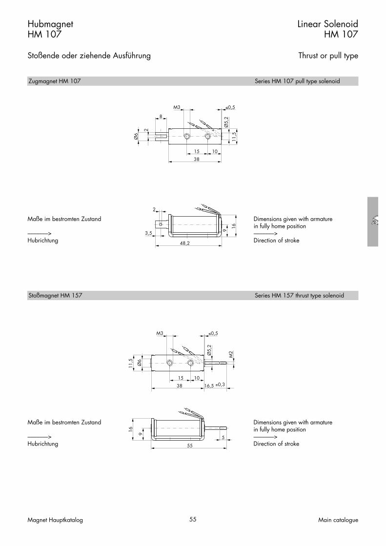
Maße im bestromten Zustand
–––––––>Hubrichtung
Dimensions given with armature in fully home position–––––––>Direction of stroke
Maße im bestromten Zustand
–––––––>Hubrichtung
Dimensions given with armature in fully home position–––––––>Direction of stroke
Zugmagnet HM 107 Series HM 107 pull type solenoid
Stoßmagnet HM 157 Series HM 157 thrust type solenoid

Weight:Complete solenoid: appr. 67 gArmature: appr. 15 g
Standard:Voltage: 24 V DCFlying leads: 10 cm
Insulation class: E (max. permissibletemperature = 120 °C)
Insulation groupaccording to: VDE 0110 B 75Test voltage: 800 V (eff)Protection: IP 00
Force vs. Stroke diagramm F = f (s)
Force measured when operating in horizontal position, at 90 % rated voltage and with winding at operating temperature
stroke s = 0 corresponds to armature infully home position
Gewicht:Magnet: ca. 67 g
Anker: ca. 15 gStandard:
Spannung: 24 V DCLitze: 10 cm
Isolierstoffklasse: E (Tgrenz = 120 °C)
Isolationsgruppenach: VDE 0110 B 75Prüfspannung: 800 V (eff)Schutzart: IP 00
Kraft-Weg-Diagramm F = f (s)
Kraft bei waagerechter Bewegungsrichtung undbei 90 % Nennspannung und betriebswarmerWicklung
Hub s = 0 entspricht dem angezogenen,bestromten Zustand
HubmagnetHM 207
Stoßende oder ziehende Ausführung
Linear SolenoidHM 207
Thrust or pull type
Magnet Hauptkatalog 56 Main catalogue
Bestellformel HM 2 07 – F – 24 V DC 100 % ED Order specificationsHubmagnetGröße
HM2
Linear solenoidSizes
Bauart
Anschlußart
Zugmagnet mit KonusankerStoßmagnet mit Konusanker
0757
Design type
Coil terminals
Pull type solenoid with conical face armatureThrust type solenoid with conical face armature
Nennspannung (Standardspannung)1)
Zulässige relative Einschaltdauer bei Luftkühlung (LK)
Litze (Standardlänge 10 cm) F24 Nominal voltage (standard voltage)1)
100 % ED Perm. duty cycle under air cooled conditions (LK)
Flying leads (10 cm standard length)
HM 2 5 7 - F
24 V DC 100% ED
1) Die Magnete sind auf Anfrage bis 60 V DClieferbar
1) Other voltages are available on request up to 60 V DC
Zul. rel. Einschaltdauer (ED)2) % 100 60 35 25 15 10 5 % Perm. duty cycle (ED)2)
Nennaufnahme P 20Anzugszeit (ED)3)
Wms
4,529
7,9 12,5 19 39 45 699
Wms
Nominal coil power P 20Actuation time (ED)3)
2) Bei Montage auf eine Kühlfläche von mindestens 45 cm2 ist die 1,3fache ED zulässig
3) Bei 5 mm Hub
2) If solenoid is mounted directly onto a flat metal surface of at least 45 cm2, the duty cycle can be extended up to 1.3 x nominal rating
3) Stroke 5 mm
0 2 4 6 8 10S [mm]
F [N
]
0,1
0,2
0,50,7
0,3
10 %ED
1
2
34568
100
35
25
60
15
510

HubmagnetHM 207
Stoßende oder ziehende Ausführung
Linear SolenoidHM 207
Thrust or pull type
Magnet Hauptkatalog 57 Main catalogue
8≤0,5
15
Ø6,
2
M4
105030
2Ø
8
3,563
1810
,5
Ø2
15
Ø6,
2
M4
105030
Ø 8
25,5±0,3
M3
6
≤0,5
77,5
1810
,5
Maße im bestromten Zustand
–––––––>Hubrichtung
Dimensions given with armature in fully home position–––––––>Direction of stroke
Maße im bestromten Zustand
–––––––>Hubrichtung
Dimensions given with armature in fully home position–––––––>Direction of stroke
Zugmagnet HM 207 Series HM 207 pull type solenoid
Stoßmagnet HM 257 Series HM 257 thrust type solenoid
Weight:Complete solenoid: appr. 27 gArmature: appr. 5 g
Standard:Voltage: 24 V DCFlying leads: 10 cm
Insulation class: E (max. permissibletemperature = 120 °C)
Insulation groupaccording to: VDE 0110 C 150Test voltage: 800 V (eff)Protection: IP 00
Force vs. Stroke diagramm F = f (s)
Force measured when operating in horizontal position, at 90 % rated voltage and with winding at operating temperature
stroke s = 0 corresponds to armature infully home position
Gewicht:Magnet: ca. 27 g
Anker: ca. 5 gStandard:
Spannung: 24 V DCLitze: 10 cm
Isolierstoffklasse: E (Tgrenz = 120 °C)
Isolationsgruppenach: VDE 0110 C 150Prüfspannung: 800 V (eff)Schutzart: IP 00
Kraft-Weg-Diagramm F = f (s)
Kraft bei waagerechter Bewegungsrichtung undbei 90 % Nennspannung und betriebswarmerWicklung
Hub s = 0 entspricht dem angezogenen,bestromten Zustand
HubmagnetHU 24
Stoßende oder ziehende Ausführung
Linear SolenoidHU 24
Thrust or pull type
Magnet Hauptkatalog 58 Main catalogue
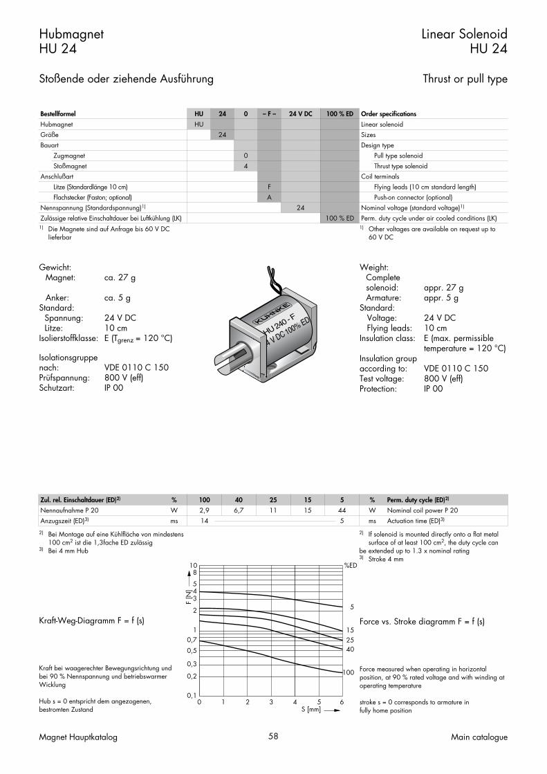
Bestellformel HU 24 0 – F – 24 V DC 100 % ED Order specificationsHubmagnetGröße
HU24
Linear solenoidSizes
Bauart
Anschlußart
ZugmagnetStoßmagnet
04
Design type
Coil terminals
Pull type solenoidThrust type solenoid
Nennspannung (Standardspannung)1)
Zulässige relative Einschaltdauer bei Luftkühlung (LK)
Litze (Standardlänge 10 cm)Flachstecker (Faston; optional)
FA
24100 % ED
Nominal voltage (standard voltage)1)
Perm. duty cycle under air cooled conditions (LK)
Flying leads (10 cm standard length)Push-on connector (optional)
HU 240 - F
24 V DC 100% ED
1) Die Magnete sind auf Anfrage bis 60 V DClieferbar
1) Other voltages are available on request up to 60 V DC
Zul. rel. Einschaltdauer (ED)2) % 100 40 25 15 5 % Perm. duty cycle (ED)2)
Nennaufnahme P 20Anzugszeit (ED)3)
Wms
2,914
6,7 11 15 445
Wms
Nominal coil power P 20Actuation time (ED)3)
2) Bei Montage auf eine Kühlfläche von mindestens 100 cm2 ist die 1,3fache ED zulässig
3) Bei 4 mm Hub
2) If solenoid is mounted directly onto a flat metal surface of at least 100 cm2, the duty cycle can
be extended up to 1.3 x nominal rating3) Stroke 4 mm
0 21 3 4 5 6S [mm]
F [N
]
0,1
0,2
0,70,5
0,3
10 %ED
100
402515
5
1
2
345
8
HubmagnetHU 24
Stoßende oder ziehende Ausführung
Linear SolenoidHU 24
Thrust or pull type
Magnet Hauptkatalog 59 Main catalogue
9 14 16
M310 7
8
2Ø6
33
1017
,5
≤0,8
Ø2
3,5 24
91416
M310 7
≤0,8
M2
40
1017
,5
24
Ø6
15 ±0,3
8
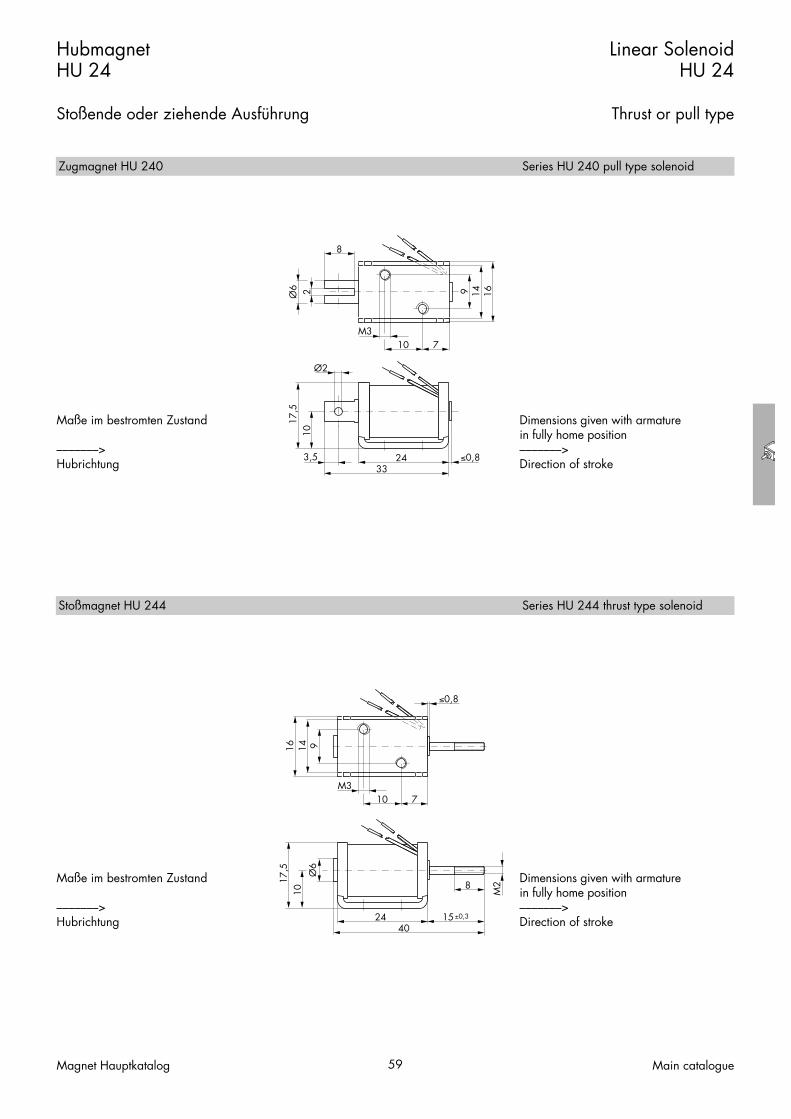
Maße im bestromten Zustand
–––––––>Hubrichtung
Dimensions given with armature in fully home position–––––––>Direction of stroke
Maße im bestromten Zustand
–––––––>Hubrichtung
Dimensions given with armature in fully home position–––––––>Direction of stroke
Zugmagnet HU 240 Series HU 240 pull type solenoid
Stoßmagnet HU 244 Series HU 244 thrust type solenoid

Weight:Complete solenoid: appr. 55 gArmature: appr. 11 g
Standard:Voltage: 24 V DCFlying leads: 10 cm
Insulation class: E (max. permissibletemperature = 120 °C)
Insulation groupaccording to: VDE 0110 B 30Test voltage: 2500 V (eff)Long life expectancy through plasticbobbin armature bearing
Force vs. Stroke diagramm F = f (s)
Force measured when operating in horizontal position, at 90 % rated voltage and with winding at operating temperature
stroke s = 0 corresponds to armature infully home position
Gewicht:Magnet: ca. 55 g
Anker: ca. 11 gStandard:
Spannung: 24 V DCLitze: 10 cm
Isolierstoffklasse: E (Tgrenz = 120 °C)
Isolationsgruppenach: VDE 0110 B 30Prüfspannung: 2500 V (eff)Hohe Lebensdauer durch Ankerlagerungim Kunststoffspulenkörper
Kraft-Weg-Diagramm F = f (s)
Kraft bei waagerechter Bewegungsrichtung undbei 90 % Nennspannung und betriebswarmerWicklung
Hub s = 0 entspricht dem angezogenen,bestromten Zustand
HubmagnetHU 32
Stoßende oder ziehende Ausführung
Linear SolenoidHU 32
Thrust or pull type
Magnet Hauptkatalog 60 Main catalogue
Bestellformel HU 32 0 – F – 24 V DC 100 % ED Order specificationsHubmagnetGröße
HU32
Linear solenoidSizes
Bauart
Anschlußart
ZugmagnetStoßmagnet
04
Design type
Coil terminals
Pull type solenoidThrust type solenoid
Nennspannung (Standardspannung)1)
Zulässige relative Einschaltdauer bei Luftkühlung (LK)
Litze (Standardlänge 10 cm)Flachstecker (Faston; optional)
FA
24100 % ED
Nominal voltage (standard voltage)1)
Perm. duty cycle under air cooled conditions (LK)
Flying leads (10 cm standard length)Push-on connector (optional)
HU 324 - F
24 V DC 100% ED
1) Die Magnete sind auf Anfrage bis 230 V DClieferbar
1) Other voltages are available on request up to230 V DC
Zul. rel. Einschaltdauer (ED)2) % 100 40 25 15 5 % Perm. duty cycle (ED)2)
Nennaufnahme P 20Anzugszeit (ED)
Wms
4,217
10 16 25 646
Wms
Nominal coil power P 20Actuation time (ED)
2) Bei Montage auf eine Kühlfläche von mindestens 100 cm2 ist die 1,3fache ED zulässig
2) If solenoid is mounted directly onto a flat metal surface of at least 100 cm2, the duty cycle can be extended up to 1.3 x nominal rating
0 1 2 3 4 75 6S [mm]
F [N
]
0,1
0,2
0,3
0,5
0,8
10 %ED
100
40
15
25
5
1
2
54
8
HubmagnetHU 32
Stoßende oder ziehende Ausführung
Linear SolenoidHU 32
Thrust or pull type
Magnet Hauptkatalog 61 Main catalogue
10 16 18
M320 6
8
2Ø8
≤0,5
32
1221
Ø2
3,541
101618
M320 6
≤0,5
4832 15 ±0,3
8
M3
1221 Ø
8
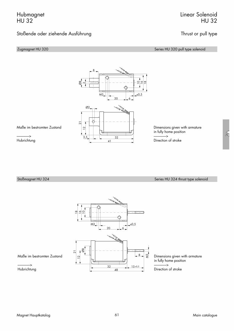
Maße im bestromten Zustand
–––––––>Hubrichtung
Dimensions given with armature in fully home position–––––––>Direction of stroke
Maße im bestromten Zustand
–––––––>Hubrichtung
Dimensions given with armature in fully home position–––––––>Direction of stroke
Zugmagnet HU 320 Series HU 320 pull type solenoid
Stoßmagnet HU 324 Series HU 324 thrust type solenoid

Magnet Hauptkatalog 62 Main catalogue

Hubmagnete H
Solenoids Series H

Weight:Complete solenoid: appr. 65 gArmature: appr. 13 g
Standard:Voltage: 24 V DCFlying leads: 10 cm
Insulation class: B (max. permissibletemperature = 130 °C)
Insulation groupaccording to: VDE 0110 B 75Test voltage: 2500 V (eff)
Long life expectancy through plasticbobbin armature bearing.The solenoid can also be supplied asspecial specification with service-free DUarmature bearing for maximumdurability.
Force vs. Stroke diagramm F = f (s)56
Conical face armatureFlat face armature
Force measured when operating in horizontal position, at 90 % rated voltage and with winding at operating temperature
stroke s = 0 corresponds to armature infully home position
Gewicht:Magnet: ca. 65 g
Anker: ca. 13 gStandard:
Spannung: 24 V DCLitze: 10 cm
Isolierstoffklasse: B (Tgrenz = 130 °C)
Isolationsgruppenach: VDE 0110 B 75Prüfspannung: 2500 V (eff)
Hohe Lebensdauer durch Ankerlagerungim Kunststoffspulenkörper.In Sonderausführung ist dieser Magnetauch mit wartungsfreier Ankerlagerung(DU-Lager) für höchste Lebensdauerlieferbar.
Kraft-Weg-Diagramm F = f (s)
KonusankerFlachanker
Kraft bei waagerechter Bewegungsrichtung undbei 90 % Nennspannung und betriebswarmerWicklung
Hub s = 0 entspricht dem angezogenen,bestromten Zustand
HubmagnetH 22
Stoßende oder ziehende Ausführung
Linear SolenoidH 22
Thrust or pull type
Magnet Hauptkatalog 64 Main catalogue
Bestellformel H 22 06 – F – 24 V DC 100 % ED Order specificationsHubmagnetGröße
H22
Linear solenoidSizes
BauartZugmagnet mit FlachankerZugmagnet mit Konusanker1)
Stoßmagnet mit Flachanker
030643
Design typePull type solenoid with flat face armaturePull type solenoid with conical face armature1)
Thrust type solenoid with flat face armature
AnschlußartStoßmagnet mit Konusanker1)
Litze (Standardlänge 10 cm)Flachstecker (optional)
Nennspannung (Standardspannung)2)
Zulässige relative Einschaltdauer bei Luftkühlung
46
FA
24
Coil terminalsThrust type solenoid with conical face armature1)
Flying leads (10 cm standard length)Push-on connector (optional)
100 % EDNominal voltage (standard voltage)2)
Perm. duty cycle under air cooled conditions (LK)
H2246-F
24 V DC 100%ED
1) Nur bei Gleichstrom2) Die Magnete sind auf Anfrage bis 230 V DC
lieferbar
1) Only available for DC2) Other voltages are available on request up to
230 V DC
Zul. rel. Einschaltdauer (ED)3) % 100 45 25 15 5 % Perm. duty cycle (ED)3)
Nennaufnahme P 20Anzugszeit (ED)
Wms
5,224
10,2 19 29,5 757
Wms
Nominal coil power P 20Actuation time (ED)
3) Bei Montage auf eine Kühlfläche von mindestens 45 cm2 ist die 1,3fache ED zulässig
3) If solenoid is mounted directly onto a flat metal surface of at least 45 cm2, the duty cycle can be extended up to 1.3 x nominal rating
0 1 2 3 4 5S [mm]
F [N
]
0,1
0,2
0,5
30 %ED
100
10025451525
5
15
45
1
23457
10
20

HubmagnetH 22
Stoßende oder ziehende Ausführung
Linear SolenoidH 22
Thrust or pull type
Magnet Hauptkatalog 65 Main catalogue
2515
20
M3 32
8
Ø8 2
48,5 0,5
8153,5
M3
Ø2
2515
20
M3 32
815
M 4 (M )
M3
64,5 0,5
25,5 0,3
15 M3
8
Maße im bestromten Zustand
–––––––>Hubrichtung
Maße im bestromten Zustand
–––––––>Hubrichtung
Dimensions given with armature in fully home position–––––––>Direction of stroke
Dimensions given with armature in fully home position–––––––>Direction of stroke
Zugmagnet H 2203/2206 Series H 2203/2206 pull type solenoid
Stoßmagnet H 2243/2246 Series H 2243/2246 thrust type solenoid

Weight:Complete solenoid: appr. 85 gArmature: appr. 25 g
Standard:Voltage: 24 V DCFlying leads: 10 cm
Insulation class: B (max. permissibletemperature = 130 °C)
Insulation groupaccording to: VDE 0110 B 75Test voltage: 2500 V (eff)Long life expectancy through plasticbobbin armature bearing.
Force vs. Stroke diagramm F = f (s)
Conical face armatureFlat face armature
Force measured when operating in horizontal position, at 90 % rated voltage and with winding at operating temperature
stroke s = 0 corresponds to armature infully home position
Gewicht:Magnet: ca. 85 g
Anker: ca. 25 gStandard:
Spannung: 24 V DCLitze: 10 cm
Isolierstoffklasse: B (Tgrenz = 130 °C)
Isolationsgruppenach: VDE 0110 B 75Prüfspannung: 2500 V (eff)Hohe Lebensdauer durch Ankerlagerungim Kunststoffspulenkörper.
Kraft-Weg-Diagramm F = f (s)
KonusankerFlachanker
Kraft bei waagerechter Bewegungsrichtung undbei 90 % Nennspannung und betriebswarmerWicklung
Hub s = 0 entspricht dem angezogenen,bestromten Zustand
HubmagnetH 24
Stoßende oder ziehende Ausführung
Linear SolenoidH 24
Thrust or pull type
Magnet Hauptkatalog 66 Main catalogue
Bestellformel H 24 06 – F – 24 V DC 100 % ED Order specificationsHubmagnetGröße
H24
Linear solenoidSizes
BauartZugmagnet mit FlachankerZugmagnet mit Konusanker1)
Stoßmagnet mit Flachanker
030643
Design typePull type solenoid with flat face armaturePull type solenoid with conical face armature1)
Thrust type solenoid with flat face armature
AnschlußartStoßmagnet mit Konusanker1)
Litze (Standardlänge 10 cm)Flachstecker (optional)
Nennspannung (Standardspannung)2)
Zulässige relative Einschaltdauer bei Luftkühlung (LK)
46
FA
24
Coil terminalsThrust type solenoid with conical face armature1)
Flying leads (10 cm standard length)Push-on connector (optional)
100 % EDNominal voltage (standard voltage)2)
Perm. duty cycle under air cooled conditions (LK)
H2446-F
24 V DC 100% ED
1) Nur bei Gleichstrom2) Die Magnete sind auf Anfrage bis 230 V DC
lieferbar
1) Only available for DC2) Other voltages are available on request up to
230 V DC
Zul. rel. Einschaltdauer (ED)3) % 100 70 45 25 15 5 % Perm. duty cycle (ED)3)
Nennaufnahme P 20Anzugszeit (ED)
Wms
623
9,1 13,8 23 40 1029
Wms
Nominal coil power P 20Actuation time (ED)
3) Bei Montage auf eine Kühlfläche von mindestens 60 cm2 ist die 1,3fache ED zulässig
3) If solenoid is mounted directly onto a flat metal surface of at least 60 cm2, the duty cycle can be extended up to 1.3 x nominal rating
0 2 4 6 8S [mm]
F [N
]
0,30,40,60,8
1
2
50 %ED
10010075705030452515
155
5
5
810
20
40
HubmagnetH 24
Stoßende oder ziehende Ausführung
Linear SolenoidH 24
Thrust or pull type
Magnet Hauptkatalog 67 Main catalogue
25
20
824M3 ≤0,5
Ø6,
5
14
4
3
4090,552
Ø10 3
25,5 0,34066,5
10 M3
25
20
824
14 Ø10
M3 ≤0,5
Ø6,
5
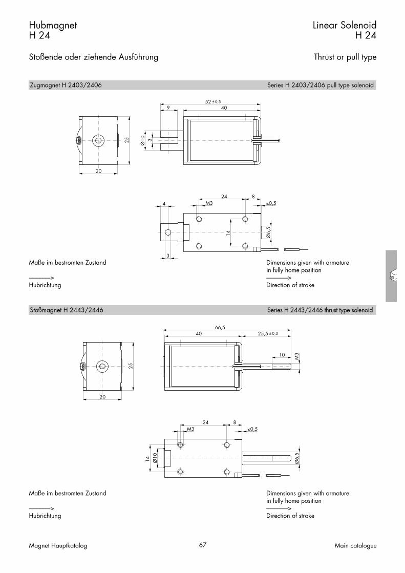
Maße im bestromten Zustand
–––––––>Hubrichtung
Dimensions given with armature in fully home position–––––––>Direction of stroke
Maße im bestromten Zustand
–––––––>Hubrichtung
Dimensions given with armature in fully home position–––––––>Direction of stroke
Zugmagnet H 2403/2406 Series H 2403/2406 pull type solenoid
Stoßmagnet H 2443/2446 Series H 2443/2446 thrust type solenoid

Weight:Complete solenoid: appr. 90 gArmature: appr. 17 g
Standard:Voltage: 24 V DCFlying leads: 10 cm
Insulation class: B (max. permissibletemperature = 130 °C)
Insulation groupaccording to: VDE 0110 C 36Test voltage: 2500 V (eff)Long life expectancy through plasticbobbin armature bearing.The solenoid can also be supplied asspecial specification with service-free DUarmature bearing for maximumdurability.
Force vs. Stroke diagramm F = f (s)
Conical face armatureFlat face armature
Force measured when operating in horizontal position, at 90 % rated voltage and with winding at operating temperature
stroke s = 0 corresponds to armature infully home position
Gewicht:Magnet: ca. 90 g
Anker: ca. 17 gStandard:
Spannung: 24 V DCLitze: 10 cm
Isolierstoffklasse: B (Tgrenz = 130 °C)
Isolationsgruppenach: VDE 0110 C 36Prüfspannung: 2500 V (eff)Hohe Lebensdauer durch Ankerlagerungim Kunststoffspulenkörper.In Sonderausführung ist dieser Magnetauch mit wartungsfreier Ankerlagerung(DU-Lager) für höchste Lebensdauerlieferbar.
Kraft-Weg-Diagramm F = f (s)
KonusankerFlachanker
Kraft bei waagerechter Bewegungsrichtung undbei 90 % Nennspannung und betriebswarmerWicklung
Hub s = 0 entspricht dem angezogenen,bestromten Zustand
HubmagnetH 32
Stoßende oder ziehende Ausführung
Linear SolenoidH 32
Thrust or pull type
Magnet Hauptkatalog 68 Main catalogue
Bestellformel H 32 06 – F – 24 V DC 100 % ED Order specificationsHubmagnetGröße
H32
Linear solenoidSizes
BauartZugmagnet mit FlachankerZugmagnet mit Konusanker1)
Stoßmagnet mit Flachanker
030643
Design typePull type solenoid with flat face armaturePull type solenoid with conical face armature1)
Thrust type solenoid with flat face armature
AnschlußartStoßmagnet mit Konusanker1)
Litze (Standardlänge 10 cm)Flachstecker (optional)
Nennspannung (Standardspannung)2)
Zulässige relative Einschaltdauer bei Luftkühlung (LK)
46
FA
24
Coil terminalsThrust type solenoid with conical face armature1)
Flying leads (10 cm standard length)Push-on connector (optional)
100 % EDNominal voltage (standard voltage)2)
Perm. duty cycle under air cooled conditions (LK)
H3246-F
24 V DC 100% ED
1) Nur bei Gleichstrom2) Die Magnete sind auf Anfrage bis 230 V DC
lieferbar
1) Only available for DC2) Other voltages are available on request up to
230 V DC
Zul. rel. Einschaltdauer (ED)3) % 100 50 25 16 6 % Perm. duty cycle (ED)3)
Nennaufnahme P 20Anzugszeit (ED)
Wms
5,221
9,6 18,2 28,5 718
Wms
Nominal coil power P 20Actuation time (ED)
3) Bei Montage auf eine Kühlfläche von mindestens 70 cm2 ist die 1,3fache ED zulässig
3) If solenoid is mounted directly onto a flat metal surface of at least 70 cm2, the duty cycle can be extended up to 1.3 x nominal rating
0 1 2 3 4 5S [mm]
F [N
]
0,10,20,30,40,60,8
30 %ED
100
50100
25
5016
6
166
25
1
23468
10
20

HubmagnetH 32
Stoßende oder ziehende Ausführung
Linear SolenoidH 32
Thrust or pull type
Magnet Hauptkatalog 69 Main catalogue
4
Ø3
Ø10
9
3
30,5
617
18
M3
30
42,5±0,5
28
M3
20
15 M3
30,5
617
Ø10
M3
30
25,5±0,3
57
28
18
M3
20
Maße im bestromten Zustand
–––––––>Hubrichtung
Dimensions given with armature in fully home position–––––––>Direction of stroke
Maße im bestromten Zustand
–––––––>Hubrichtung
Dimensions given with armature in fully home position–––––––>Direction of stroke
Zugmagnet H 3203/3206 Series H 3203/3206 pull type solenoid
Stoßmagnet H 3243/3246 Series H 3243/3246 thrust type solenoid

Weight:Complete solenoid: appr. 140 gArmature: appr. 32 g
Standard:Voltage: 24 V DCFlying leads: 10 cm
Insulation class: B (max. permissibletemperature = 130 °C)
Insulation groupaccording to: VDE 0110 1.5 KV/3Test voltage: 2500 V (eff)Long life expectancy through plasticbobbin armature bearing.The solenoid can also be supplied asspecial specification with service-free DUarmature bearing for maximumdurability.
Force vs. Stroke diagramm F = f (s)
Conical face armatureFlat face armature
Force measured when operating in horizontal position, at 90 % rated voltage and with winding at operating temperature
stroke s = 0 corresponds to armature infully home position
Gewicht:Magnet: ca. 140 g
Anker: ca. 32 gStandard:
Spannung: 24 V DCLitze: 10 cm
Isolierstoffklasse: B (Tgrenz = 130 °C)
Isolationsgruppenach: VDE 0110 1,5 KV/3Prüfspannung: 2500 V (eff)Hohe Lebensdauer durch Ankerlagerungim Kunststoffspulenkörper.In Sonderausführung ist dieser Magnetauch mit wartungsfreier Ankerlagerung(DU-Lager) für höchste Lebensdauerlieferbar.
Kraft-Weg-Diagramm F = f (s)
KonusankerFlachanker
Kraft bei waagerechter Bewegungsrichtung undbei 90 % Nennspannung und betriebswarmerWicklung
Hub s = 0 entspricht dem angezogenen,bestromten Zustand
HubmagnetH 34
Stoßende oder ziehende Ausführung
Linear SolenoidH 34
Thrust or pull type
Magnet Hauptkatalog 70 Main catalogue
Bestellformel H 34 06 – F – 24 V DC 100 % ED Order specificationsHubmagnetGröße
H34
Linear solenoidSizes
BauartZugmagnet mit FlachankerZugmagnet mit Konusanker1)
Stoßmagnet mit Flachanker
030643
Design typePull type solenoid with flat face armaturePull type solenoid with conical face armature1)
Thrust type solenoid with flat face armature
AnschlußartStoßmagnet mit Konusanker1)
Litze (Standardlänge 10 cm)Flachstecker (optional)
Nennspannung (Standardspannung)2)
Zulässige relative Einschaltdauer bei Luftkühlung (LK)
46
FA
24
Coil terminalsThrust type solenoid with conical face armature1)
Flying leads (10 cm standard length)Push-on connector (optional)
100 % EDNominal voltage (standard voltage)2)
Perm. duty cycle under air cooled conditions (LK)
H3406-F
24 V DC 100% ED
1) Nur bei Gleichstrom2) Die Magnete sind auf Anfrage bis 230 V DC
lieferbar
1) Only available for DC2) Other voltages are available on request up to
230 V DC
Zul. rel. Einschaltdauer (ED)3) % 100 35 25 15 5 % Perm. duty cycle (ED)3)
Nennaufnahme P 20Anzugszeit (ED)
Wms
845
23 30 57 14416
Wms
Nominal coil power P 20Actuation time (ED)
3) Bei Montage auf eine Kühlfläche von mindestens 100 cm2 ist die 1,3fache ED zulässig
3) If solenoid is mounted directly onto a flat metal surface of at least 100 cm2, the duty cycle can beextended up to 1.3 x nominal rating
0 2 4 6 8 10 120,1
0,2
0,5
%ED
100
1
2
57
10
203050
352515
55
S [mm]
F [N
]

HubmagnetH 34
Stoßende oder ziehende Ausführung
Linear SolenoidH 34
Thrust or pull type
Magnet Hauptkatalog 71 Main catalogue
4
32 9
Ø3
M3
18
Ø12
9
3
49,560±0,5
30
26
M3
20
49,5 2676,9
±0,3
30
26
M3
20
10 M3
Ø12
32 9M3
18
Maße im bestromten Zustand
–––––––>Hubrichtung
Dimensions given with armature in fully home position
Direction of stroke –––––––>
Maße im bestromten Zustand
–––––––>Hubrichtung
Dimensions given with armature in fully home position–––––––>Direction of stroke
Zugmagnet H 3403/3406 Series H 3403/3406 pull type solenoid
Stoßmagnet H 3443/3446 Series H 3443/3446 thrust type solenoid
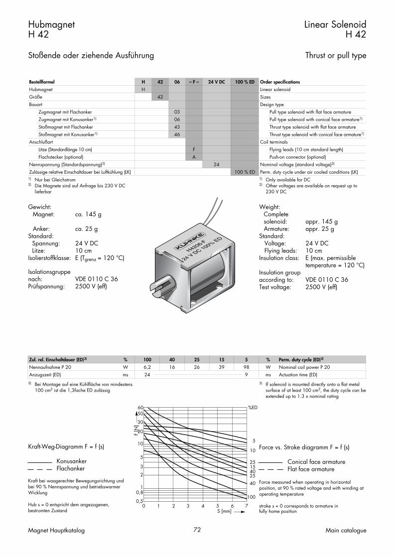
Weight:Complete solenoid: appr. 145 gArmature: appr. 25 g
Standard:Voltage: 24 V DCFlying leads: 10 cm
Insulation class: E (max. permissibletemperature = 120 °C)
Insulation groupaccording to: VDE 0110 C 36Test voltage: 2500 V (eff)
Force vs. Stroke diagramm F = f (s)
Conical face armatureFlat face armature
Force measured when operating in horizontal position, at 90 % rated voltage and with winding at operating temperature
stroke s = 0 corresponds to armature infully home position
Gewicht:Magnet: ca. 145 g
Anker: ca. 25 gStandard:
Spannung: 24 V DCLitze: 10 cm
Isolierstoffklasse: E (Tgrenz = 120 °C)
Isolationsgruppenach: VDE 0110 C 36Prüfspannung: 2500 V (eff)
Kraft-Weg-Diagramm F = f (s)
KonusankerFlachanker
Kraft bei waagerechter Bewegungsrichtung undbei 90 % Nennspannung und betriebswarmerWicklung
Hub s = 0 entspricht dem angezogenen,bestromten Zustand
HubmagnetH 42
Stoßende oder ziehende Ausführung
Linear SolenoidH 42
Thrust or pull type
Magnet Hauptkatalog 72 Main catalogue
Bestellformel H 42 06 – F – 24 V DC 100 % ED Order specificationsHubmagnetGröße
H42
Linear solenoidSizes
BauartZugmagnet mit FlachankerZugmagnet mit Konusanker1)
Stoßmagnet mit Flachanker
030643
Design typePull type solenoid with flat face armaturePull type solenoid with conical face armature1)
Thrust type solenoid with flat face armature
AnschlußartStoßmagnet mit Konusanker1)
Litze (Standardlänge 10 cm)Flachstecker (optional)
Nennspannung (Standardspannung)2)
Zulässige relative Einschaltdauer bei Luftkühlung (LK)
46
FA
24
Coil terminalsThrust type solenoid with conical face armature1)
Flying leads (10 cm standard length)Push-on connector (optional)
100 % EDNominal voltage (standard voltage)2)
Perm. duty cycle under air cooled conditions (LK)
H4206-F
24 V DC 100% ED
1) Nur bei Gleichstrom2) Die Magnete sind auf Anfrage bis 230 V DC
lieferbar
1) Only available for DC2) Other voltages are available on request up to
230 V DC
Zul. rel. Einschaltdauer (ED)3) % 100 40 25 15 5 % Perm. duty cycle (ED)3)
Nennaufnahme P 20Anzugszeit (ED)
Wms
6,224
16 26 39 989
Wms
Nominal coil power P 20Actuation time (ED)
3) Bei Montage auf eine Kühlfläche von mindestens 100 cm2 ist die 1,3fache ED zulässig
3) If solenoid is mounted directly onto a flat metal surface of at least 100 cm2, the duty cycle can beextended up to 1.3 x nominal rating
0 1 2 3 4 5 6 7S [mm]
F [N
]
0,5
10,8
23
60 %ED
100
4025401525
10
5
5
10
20
30
50

HubmagnetH 42
Stoßende oder ziehende Ausführung
Linear SolenoidH 42
Thrust or pull type
Magnet Hauptkatalog 73 Main catalogue
35
34
M3
25
36
9
Ø10 3
48 ±0,5
17 12
Ø318
4
M3
Maße im bestromten Zustand
–––––––>Hubrichtung
Dimensions given with armature in fully home position–––––––>Direction of stroke
35
34
M3
25
36 25,5±0,3
17 12
M3
18
15
M3
Maße im bestromten Zustand
–––––––>Hubrichtung
Dimensions given with armature in fully home position–––––––>Direction of stroke
Zugmagnet H 4203/4206 Series H 4203/4206 pull type solenoid
Stoßmagnet H 4243/4246 Series H 4243/4246 thrust type solenoid
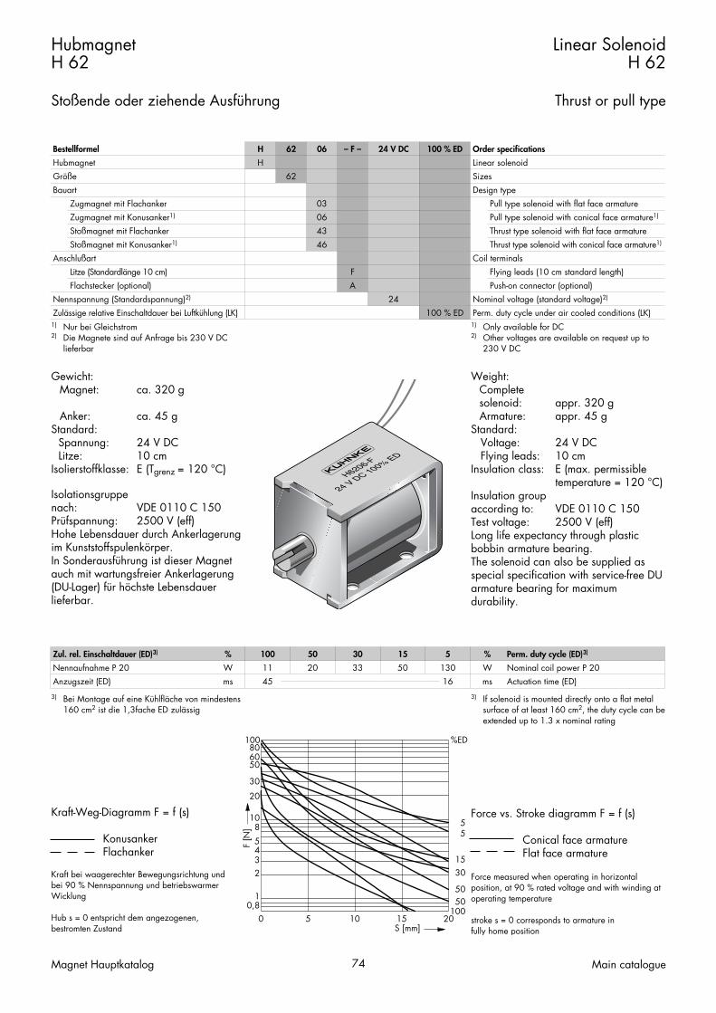
Weight:Complete solenoid: appr. 320 gArmature: appr. 45 g
Standard:Voltage: 24 V DCFlying leads: 10 cm
Insulation class: E (max. permissibletemperature = 120 °C)
Insulation groupaccording to: VDE 0110 C 150Test voltage: 2500 V (eff)Long life expectancy through plasticbobbin armature bearing.The solenoid can also be supplied asspecial specification with service-free DUarmature bearing for maximumdurability.
Force vs. Stroke diagramm F = f (s)
Conical face armatureFlat face armature
Force measured when operating in horizontal position, at 90 % rated voltage and with winding at operating temperature
stroke s = 0 corresponds to armature infully home position
Gewicht:Magnet: ca. 320 g
Anker: ca. 45 gStandard:
Spannung: 24 V DCLitze: 10 cm
Isolierstoffklasse: E (Tgrenz = 120 °C)
Isolationsgruppenach: VDE 0110 C 150Prüfspannung: 2500 V (eff)Hohe Lebensdauer durch Ankerlagerungim Kunststoffspulenkörper.In Sonderausführung ist dieser Magnetauch mit wartungsfreier Ankerlagerung(DU-Lager) für höchste Lebensdauerlieferbar.
Kraft-Weg-Diagramm F = f (s)
KonusankerFlachanker
Kraft bei waagerechter Bewegungsrichtung undbei 90 % Nennspannung und betriebswarmerWicklung
Hub s = 0 entspricht dem angezogenen,bestromten Zustand
HubmagnetH 62
Stoßende oder ziehende Ausführung
Linear SolenoidH 62
Thrust or pull type
Magnet Hauptkatalog 74 Main catalogue
Bestellformel H 62 06 – F – 24 V DC 100 % ED Order specificationsHubmagnetGröße
H62
Linear solenoidSizes
BauartZugmagnet mit FlachankerZugmagnet mit Konusanker1)
Stoßmagnet mit Flachanker
030643
Design typePull type solenoid with flat face armaturePull type solenoid with conical face armature1)
Thrust type solenoid with flat face armature
AnschlußartStoßmagnet mit Konusanker1)
Litze (Standardlänge 10 cm)Flachstecker (optional)
Nennspannung (Standardspannung)2)
Zulässige relative Einschaltdauer bei Luftkühlung (LK)
46
FA
24
Coil terminalsThrust type solenoid with conical face armature1)
Flying leads (10 cm standard length)Push-on connector (optional)
100 % EDNominal voltage (standard voltage)2)
Perm. duty cycle under air cooled conditions (LK)
H6206-F
24 V DC 100% ED
1) Nur bei Gleichstrom2) Die Magnete sind auf Anfrage bis 230 V DC
lieferbar
1) Only available for DC2) Other voltages are available on request up to
230 V DC
Zul. rel. Einschaltdauer (ED)3) % 100 50 30 15 5 % Perm. duty cycle (ED)3)
Nennaufnahme P 20Anzugszeit (ED)
Wms
1145
20 33 50 13016
Wms
Nominal coil power P 20Actuation time (ED)
3) Bei Montage auf eine Kühlfläche von mindestens 160 cm2 ist die 1,3fache ED zulässig
3) If solenoid is mounted directly onto a flat metal surface of at least 160 cm2, the duty cycle can beextended up to 1.3 x nominal rating
0 5 10 15 20S [mm]
F [N
]
0,81
23458
100 %ED
1005050
3015
5510
20
806050
30

HubmagnetH 62
Stoßende oder ziehende Ausführung
Linear SolenoidH 62
Thrust or pull type
Magnet Hauptkatalog 75 Main catalogue
Ø13
10
5,5
50
63 ±0,5
4
Ø4
1225
27
M3
44
38
34
27
M3
Maße im bestromten Zustand
–––––––>Hubrichtung
Dimensions given with armature in fully home position–––––––>Direction of stroke
50 30,5±0,5
82,5
44
38
34
27
M3
Ø13
1225
27
M3
10
M4
Maße im bestromten Zustand
–––––––>Hubrichtung
Dimensions given with armature in fully home position–––––––>Direction of stroke
Zugmagnet H 6203/6206 Series H 6203/6206 pull type solenoid
Stoßmagnet H 6243/6246 Series H 6243/6246 thrust type solenoid

Magnet Hauptkatalog 76 Main catalogue

Hubmagnete UH, HR, HL
Solenoids Series UH, HR, HL
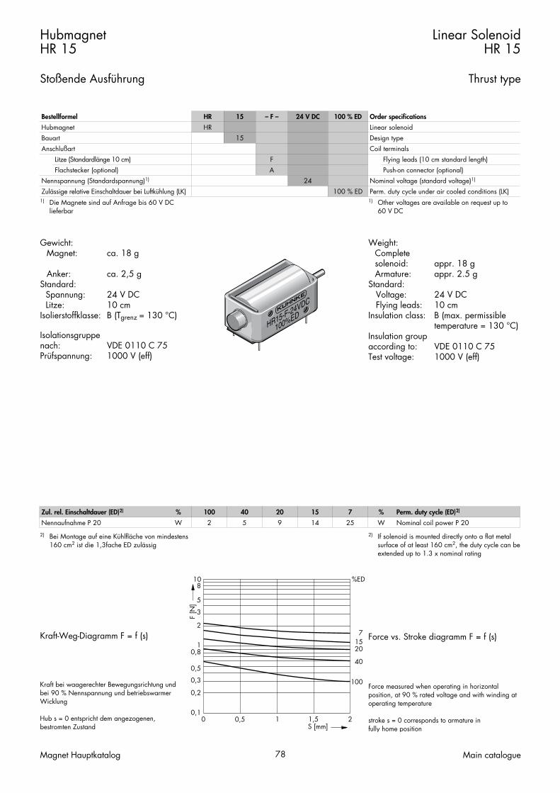
Weight:Complete solenoid: appr. 18 gArmature: appr. 2.5 g
Standard:Voltage: 24 V DCFlying leads: 10 cm
Insulation class: B (max. permissibletemperature = 130 °C)
Insulation groupaccording to: VDE 0110 C 75Test voltage: 1000 V (eff)
Force vs. Stroke diagramm F = f (s)
Force measured when operating in horizontal position, at 90 % rated voltage and with winding at operating temperature
stroke s = 0 corresponds to armature infully home position
Gewicht:Magnet: ca. 18 g
Anker: ca. 2,5 gStandard:
Spannung: 24 V DCLitze: 10 cm
Isolierstoffklasse: B (Tgrenz = 130 °C)
Isolationsgruppenach: VDE 0110 C 75Prüfspannung: 1000 V (eff)
Kraft-Weg-Diagramm F = f (s)
Kraft bei waagerechter Bewegungsrichtung undbei 90 % Nennspannung und betriebswarmerWicklung
Hub s = 0 entspricht dem angezogenen,bestromten Zustand
HubmagnetHR 15
Stoßende Ausführung
Linear SolenoidHR 15
Thrust type
Magnet Hauptkatalog 78 Main catalogue
HR15-F-24VDC
100%ED
Zul. rel. Einschaltdauer (ED)2) % 100 40 20 15 7 % Perm. duty cycle (ED)2)
Nennaufnahme P 20 W 2 5 9 14 25 W Nominal coil power P 202) Bei Montage auf eine Kühlfläche von mindestens
160 cm2 ist die 1,3fache ED zulässig2) If solenoid is mounted directly onto a flat metal
surface of at least 160 cm2, the duty cycle can beextended up to 1.3 x nominal rating
Bestellformel HR 15 – F – 24 V DC 100 % ED Order specificationsHubmagnetBauart
HR15
Linear solenoidDesign type
Anschlußart
Nennspannung (Standardspannung)1)
Litze (Standardlänge 10 cm)Flachstecker (optional)
FA
24
Coil terminalsFlying leads (10 cm standard length)
Nominal voltage (standard voltage)1)
Push-on connector (optional)
Zulässige relative Einschaltdauer bei Luftkühlung (LK) 100 % ED Perm. duty cycle under air cooled conditions (LK)1) Die Magnete sind auf Anfrage bis 60 V DC
lieferbar1) Other voltages are available on request up to
60 V DC
0 0,5 1 1,5 2S [mm]
F [N
]
0,1
0,2
0,3
0,5
0,8
10 %ED
100
40
2015
7
1
2
3
5
8

HubmagnetHR 15
Stoßende Ausführung
Linear SolenoidHR 15
Thrust type
Magnet Hauptkatalog 79 Main catalogue
25 9,535
0,42 ±0,2
Ø4,
5
12
7,6±0
,1
145,5M2
10,47
3
1,36
19,05±0,1 2,50,63 Ø1,5
Ø3
Ø1,
5
15
Maße im bestromten Zustand
–––––––>Hubrichtung
Dimensions given with armature in fully home position–––––––>Direction of stroke

Weight:Complete solenoid: appr. 135 gArmature: appr. 20 g
Standard:Voltage: 24 V DCFlying leads: 10 cm
Insulation class: E (max. permissibletemperature = 120 °C)
Insulation groupaccording to: VDE 0110 C 300Test voltage: 2500 V (eff)
Force vs. Stroke diagramm F = f (s)
Force measured when operating in horizontal position, at 90 % rated voltage and with winding at operating temperature
stroke s = 0 corresponds to armature infully home position
Gewicht:Magnet: ca. 135 g
Anker: ca. 20 gStandard:
Spannung: 24 V DCLitze: 10 cm
Isolierstoffklasse: E (Tgrenz = 120 °C)
Isolationsgruppenach: VDE 0110 C 300Prüfspannung: 2500 V (eff)
Kraft-Weg-Diagramm F = f (s)
Kraft bei waagerechter Bewegungsrichtung undbei 90 % Nennspannung und betriebswarmerWicklung
Hub s = 0 entspricht dem angezogenen,bestromten Zustand
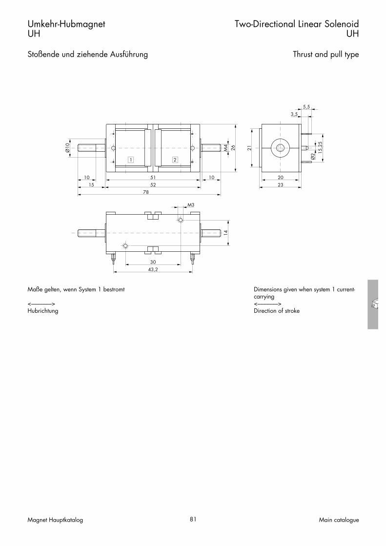
Umkehr-HubmagnetUH
Stoßende und ziehende Ausführung
Two-Directional Linear SolenoidUH
Thrust and pull type
Magnet Hauptkatalog 80 Main catalogue
UH2-L
24 VDC 100%ED
Bestellformel UH 2 – L – 24 V DC 100 % ED Order specificationsHubmagnetBauart
UH2
Linear solenoidDesign type
Anschlußart
Nennspannung (Standardspannung)1)
Litze (Standardlänge 10 cm)Lötpins
FL
24
Coil terminalsFlying leads (10 cm standard length)
Nominal voltage (standard voltage)1)
Soldering pins
Zulässige relative Einschaltdauer bei Luftkühlung (LK) 100 % ED Perm. duty cycle under air cooled conditions (LK)1) Die Magnete sind auf Anfrage bis 30 V DC
lieferbar1) Other voltages are available on request up to
30 V DC
0 1 2 3 4S [mm]
F [N
]
1
2
3
5
8
100 %ED
100
50
25
15
510
20
30
50
80
Zul. rel. Einschaltdauer (ED)2) % 100 50 25 15 5 % Perm. duty cycle (ED)2)
Nennaufnahme P 20 W 8,3 16 30 46 115 W Nominal coil power P 202) Bei Montage auf eine Kühlfläche von mindestens
160 cm2 ist die 1,3fache ED zulässig2) If solenoid is mounted directly onto a flat metal
surface of at least 160 cm2, the duty cycle can beextended up to 1.3 x nominal rating
Umkehr-HubmagnetUH
Stoßende und ziehende Ausführung
Two-Directional Linear SolenoidUH
Thrust and pull type
Magnet Hauptkatalog 81 Main catalogue
1 2
51 2023
3043,2
10
M4
Ø2
Ø10 26
15,2
5
14
21
10
3,55,5
M3
1578
52
Maße gelten, wenn System 1 bestromt
<–––––––>Hubrichtung
Dimensions given when system 1 current-carrying<–––––––>Direction of stroke

Weight:Complete solenoid: appr. 75 gArmature: appr. 21 g
Standard:Voltage: 24 V DCFlying leads: 10 cm
Insulation class: B (max. permissibletemperature = 130 °C)
Insulation groupaccording to: VDE 0110/4 KV/3Test voltage: 2.5 KV (eff)
Service-free DU armature bearing formaximum durability.Return spring optional.Observe correct mounting (armatureweight).
Force vs. Stroke diagramm F = f (s)
Force measured when operating in horizontal position, at 90 % rated voltage and with winding at operating temperature
stroke s = 0 corresponds to armature infully home position
Gewicht:Magnet: ca. 75 g
Anker: ca. 21 gStandard:
Spannung: 24 V DCLitze: 10 cm
Isolierstoffklasse: B (Tgrenz = 130 °C)
Isolationsgruppenach: VDE 0110/4 KV/3Prüfspannung: 2,5 KV (eff)
Wartungsfreie Ankerlagerung (DU-Lager) für höchste Lebensdauer.In Sonderausführung mit eingebauterRückholfeder lieferbar (auf Anfrage).Einbaulage (Ankergewicht) beachten.
Kraft-Weg-Diagramm F = f (s)
Kraft bei waagerechter Bewegungsrichtung undbei 90 % Nennspannung und betriebswarmerWicklung
Hub s = 0 entspricht dem angezogenen,bestromten Zustand
HubmagnetHL 218
Stoßende und ziehende Ausführung
Linear SolenoidHL 218
Thrust and pull type
Magnet Hauptkatalog 82 Main catalogue
Zul. rel. Einschaltdauer (ED)3) % 100 40 20 10 6 % Perm. duty cycle (ED)3)
Nennaufnahme P 20 W 5 13 25 48 77 W Nominal coil power P 20
3) Bei Montage auf eine Kühlfläche ist eine höhere ED zulässig (bitte anfragen)
3) If solenoid is mounted directly onto a flat metal surface the duty cycle can be extended (please ask for advice)
Bestellformel HL 218 – F – 24 V DC 100 % ED Order specificationsHubmagnetBauart
HL218
Linear solenoidDesign type
Anschlußart
Nennspannung (Standardspannung)1)
Litze (Standardlänge 10 cm)Steckkontakt (2,8 x 0,5 DIN 46247; optional)
FA
24
Coil terminalsFlying leads (10 cm standard length)
Nominal voltage (standard voltage)1)
Steckkontakt (2.8 x 0.5 DIN 46247; optional)
Zulässige relative Einschaltdauer bei Luftkühlung (LK)2) 100 % ED Perm. duty cycle under air cooled conditions (LK)2)
1) Andere Spannung bis max. 220 V DC auf Anfrage.2) Andere ED als 100 % ED auf Anfrage.
1) Other voltages up to max. 220 V DC on request.2) Other ED than 100 % ED on request.
0 1 2 3 4 5 6S [mm]
F [N
]
0,1
0,20,3
0,5
30
10
%ED
40
20
106
100
23
58
1

HubmagnetHL 218
Stoßende und ziehende Ausführung
Linear SolenoidHL 218
Thrust and pull type
Magnet Hauptkatalog 83 Main catalogue
20
12
M3
10
Ø3
48
M3
36 37,5
9
48
25,5
Ø10 3
Ø14 25
21
Maße im bestromten Zustand
–––––––>Hubrichtung
Dimensions given with armature in fullyhome position–––––––>Direction of stroke

Weight:Complete solenoid: appr. 133 gArmature: appr. 35 g
Standard:Voltage: 24 V DCFlying leads: 10 cm
Insulation class: B (max. permissibletemperature = 130 °C)
Insulation groupaccording to: VDE 0110/4 KV/3Test voltage: 2.5 KV (eff)
Service-free DU armature bearing formaximum durability.Return spring optional.Observe correct mounting (armatureweight).
Force vs. Stroke diagramm F = f (s)
Force measured when operating in horizontal position, at 90 % rated voltage and with winding at operating temperature
stroke s = 0 corresponds to armature infully home position
Gewicht:Magnet: ca. 133 g
Anker: ca. 35 gStandard:
Spannung: 24 V DCLitze: 10 cm
Isolierstoffklasse: B (Tgrenz = 130 °C)
Isolationsgruppenach: VDE 0110/4 KV/3Prüfspannung: 2,5 KV (eff)
Wartungsfreie Ankerlagerung (DU-Lager) für höchste Lebensdauer.In Sonderausführung mit eingebauterRückholfeder lieferbar (auf Anfrage).Einbaulage (Ankergewicht) beachten.
Kraft-Weg-Diagramm F = f (s)
Kraft bei waagerechter Bewegungsrichtung undbei 90 % Nennspannung und betriebswarmerWicklung
Hub s = 0 entspricht dem angezogenen,bestromten Zustand
HubmagnetHL 318
Stoßende und ziehende Ausführung
Linear SolenoidHL 318
Thrust and pull type
Magnet Hauptkatalog 84 Main catalogue
Zul. rel. Einschaltdauer (ED)3) % 100 40 20 10 6 % Perm. duty cycle (ED)3)
Nennaufnahme P 20 W 6,5 14 27 52 84 W Nominal coil power P 20
3) Bei Montage auf eine Kühlfläche ist eine höhere ED zulässig (bitte anfragen)
3) If solenoid is mounted directly onto a flat metal surface the duty cycle can be extended (please ask for advice)
Bestellformel HL 318 – F – 24 V DC 100 % ED Order specificationsHubmagnetBauart
HL318
Linear solenoidDesign type
Anschlußart
Nennspannung (Standardspannung)1)
Litze (Standardlänge 10 cm)Steckkontakt (2,8 x 0,5 DIN 46247; optional)
FA
24
Coil terminalsFlying leads (10 cm standard length)
Nominal voltage (standard voltage)1)
Steckkontakt (2.8 x 0.5 DIN 46247; optional)
Zulässige relative Einschaltdauer bei Luftkühlung (LK)2) 100 % ED Perm. duty cycle under air cooled conditions (LK)2)
1) Andere Spannung bis max. 220 V DC auf Anfrage.2) Andere ED als 100 % ED auf Anfrage.
1) Other voltages up to max. 220 V DC on request.2) Other ED than 100 % ED on request.
0 2 4 6 8 10 12S [mm]
F [N
]
0,1
0,2
0,5
30
10
%ED
40
20
20
6
100
1
2
57

HubmagnetHL 318
Stoßende und ziehende Ausführung
Linear SolenoidHL 318
Thrust and pull type
Magnet Hauptkatalog 85 Main catalogue
Ø12 3
Ø17
25,5421243
57
12
Ø3
12
524
M3
M39
3018
1224
M3
Maße im bestromten Zustand
–––––––>Hubrichtung
Dimensions given with armature in fullyhome position–––––––>Direction of stroke

Weight:Complete solenoid: appr. 390 gArmature: appr. 90 g
Standard:Voltage: 24 V DCFlying leads: 10 cm
Insulation class: B (max. permissibletemperature = 130 °C)
Insulation groupaccording to: VDE 0110/4 KV/3Test voltage: 2.5 KV (eff)Service-free DU armature bearing formaximum durability. Return springoptional. Observe correct mounting(armature weight).
Force vs. Stroke diagramm F = f (s)
Force measured when operating in horizontal position, at 90 % rated voltage and with winding at operating temperature
stroke s = 0 corresponds to armature infully home position
Gewicht:Magnet: ca. 390 g
Anker: ca. 90 gStandard:
Spannung: 24 V DCLitze: 10 cm
Isolierstoffklasse: B (Tgrenz = 130 °C)
Isolationsgruppenach: VDE 0110/4 KV/3Prüfspannung: 2,5 KV (eff)Wartungsfreie Ankerlagerung (DU-Lager) für höchste Lebensdauer.In Sonderausführung mit eingebauterRückholfeder lieferbar (auf Anfrage).Einbaulage (Ankergewicht) beachten.
Kraft-Weg-Diagramm F = f (s)
Kraft bei waagerechter Bewegungsrichtung undbei 90 % Nennspannung und betriebswarmerWicklung
Hub s = 0 entspricht dem angezogenen,bestromten Zustand
HubmagnetHL 618
Stoßende und ziehende Ausführung
Linear SolenoidHL 618
Thrust and pull type
Magnet Hauptkatalog 86 Main catalogue
Zul. rel. Einschaltdauer (ED)3) % 100 40 20 10 6 % Perm. duty cycle (ED)3)
Nennaufnahme P 20 W 12 31 50 96 140 W Nominal coil power P 20
3) Bei Montage auf eine Kühlfläche ist eine höhere ED zulässig (bitte anfragen)
3) If solenoid is mounted directly onto a flat metal surface the duty cycle can be extended (please ask for advice)
Bestellformel HL 618 – F – 24 V DC 100 % ED Order specificationsHubmagnetBauart
HL618
Linear solenoidDesign type
Anschlußart
Nennspannung (Standardspannung)1)
Litze (Standardlänge 10 cm)Steckkontakt (6,3 x 0,8 DIN 46247; optional)
FA
24
Coil terminalsFlying leads (10 cm standard length)
Nominal voltage (standard voltage)1)
Steckkontakt (6.3 x 0.8 DIN 46247; optional)
Zulässige relative Einschaltdauer bei Luftkühlung (LK)2) 100 % ED Perm. duty cycle under air cooled conditions (LK)2)
1) Andere Spannung bis max. 220 V DC auf Anfrage.2) Andere ED als 100 % ED auf Anfrage.
1) Other voltages up to max. 220 V DC on request.2) Other ED than 100 % ED on request.
0 5 10 15 20 S [mm]
F [N
]
0,1
0,2
0,5
100 %ED
100
4020
106
1
2
58
10
203050

HubmagnetHL 618
Stoßende und ziehende Ausführung
Linear SolenoidHL 618
Thrust and pull type
Magnet Hauptkatalog 87 Main catalogue
Ø18 6
Ø25
30,5501652
70
M4
4530
20
38
20
12
30
M4
Ø4
8 M410
Maße im bestromten Zustand
–––––––>Hubrichtung
Dimensions given with armature in fullyhome position–––––––>Direction of stroke

Magnet Hauptkatalog 88 Main catalogue