koba-step precision step gauge - s-t-group.com · precision step gauge + data-analysis software = a...
TRANSCRIPT
PRECISIONSTEP GAUGE
+DATA-ANALYSIS SOFTWARE
=A COMPLETE SYSTEM FORMONITORING COORDINATEM E A S U R I N G M A C H I N E S
KOLB & BAUMANN GMBH & CO. KGPRECISION MEASURING TOOLS MAKERSDE-63741 ASCHAFFENBURG · DAIMLERSTR. 24
G E R M A N YPHONE +49 (6021) 3463-0 · FAX +49 (6021) 3463-40w w w. k o b a . d e · m e s s z e u g e @ k o b a . d e
Catalogue No. 6100/E/01/2008
®KOBA-step
formore than
60years
Made in Germany

Contents Page
Step gauges for checking the accuracy of co-ordinate measuring machines 3
Graphic representation and analysis 4
Comparison between the test standardsgauge blocks and step gauges 4
Special features and advantagesof the KOBA-step 4
Accessoires 6
Calibration 6
Alignment of the KOBA-step 6
Practical use 8
Contents Page
Conducting formal acceptance proceduresand monitoring the precisions of machine toolsand robotic dimensional-gauging systems 9
Standard nominal lengths 10
Advantages, Software 12
KOBA-step mini 13
KOBA-step: A brief review 14
Reference 14
Your Contact Persons at KOBA 15
We reserve the right to make changes in design, dimensions, make up of sets and weightswithout prior notice.
All reproductions, even partial, of text and illustrations require our consent.
Catalogue No. 6100/E/01/2008Printed in Germany Rückziegel Druck GmbH, Stiftsgasse 17, DE-63739 Aschaffenburg
On the step gauge, spacings of different kinds for ma-king test measurement are all available simultaneously,as follows:
– Outside dimension Le e.g. with the probe head in po-sitions I and II /Fig. 2)
– Inside dimension Li e.g. with probe head in positionsIII and IV (Fig. 3)
– Rear-face to rear-face dimension Ls e.g. with probehead in positions III and V (Fig. 3)
– Front-face to front-face dimension Ls e.g. with probehead in positions VI and IV (Fig. 3)
– Positional length (Lp of a gauge face from the datumgauge face, e.g. with probe head in positions VI and0 (Fig. 3)
The illustrations show only one of many options availa-ble for each type and size of spacing. In magnitude, thedifferences between the length value La indicated by theco-ordinate measuring machine or printed or displayedby its output processor and the true value Lr of the mea-surement uncertainty U.What this means is that La can be both larger and smal-ler than Lr.The value of the length measurement uncertainty is ge-nerally given in the form of a length-dependent formu-la: U = A + K · L � B.
A distinction should be made between the figure U1spe-cified for one-dimensional test measurements along aco-ordinate axis (with terms A1, K1, B1), the figure U2 fortwo-dimensional test measurements made diagonallyin a co-ordinate plane (with terms A2, K2, B2) and thefigure U3 for three-dimensional test measurementsmade diagonally in the three-dimensional space defi-ned by the co-ordinates (with terms A3, K3, B3).
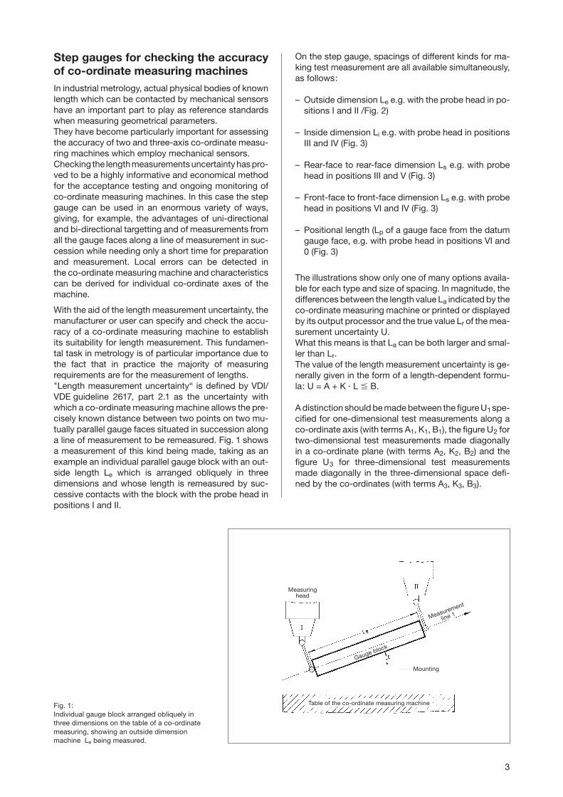
Step gauges for checking the accuracyof co-ordinate measuring machinesIn industrial metrology, actual physical bodies of knownlength which can be contacted by mechanical sensorshave an important part to play as reference standardswhen measuring geometrical parameters.They have become particularly important for assessingthe accuracy of two and three-axis co-ordinate measu-ring machines which employ mechanical sensors.Checking the length measurements uncertainty has pro-ved to be a highly informative and economical methodfor the acceptance testing and ongoing monitoring ofco-ordinate measuring machines. In this case the stepgauge can be used in an enormous variety of ways,giving, for example, the advantages of uni-directionaland bi-directional targetting and of measurements fromall the gauge faces along a line of measurement in suc-cession while needing only a short time for preparationand measurement. Local errors can be detected inthe co-ordinate measuring machine and characteristicscan be derived for individual co-ordinate axes of themachine.
With the aid of the length measurement uncertainty, themanufacturer or user can specify and check the accu-racy of a co-ordinate measuring machine to establishits suitability for length measurement. This fundamen-tal task in metrology is of particular importance due tothe fact that in practice the majority of measuringrequirements are for the measurement of lengths."Length measurement uncertainty“ is defined by VDI/VDE guideline 2617, part 2.1 as the uncertainty withwhich a co-ordinate measuring machine allows the pre-cisely known distance between two points on two mu-tually parallel gauge faces situated in succession alonga line of measurement to be remeasured. Fig. 1 showsa measurement of this kind being made, taking as anexample an individual parallel gauge block with an out-side length Le which is arranged obliquely in threedimensions and whose length is remeasured by suc-cessive contacts with the block with the probe head inpositions I and II.
Fig. 1:Individual gauge block arranged obliquely inthree dimensions on the table of a co-ordinatemeasuring, showing an outside dimension machine Le being measured.
Measuringhead
Measurement
line 1
Table of the co-ordinate measuring machine
Gauge block
Mounting
3

Graphic representation and analysis
Length measurement uncertainty plot
For the purposes of graphic analysis, the differences�L = La – Lr which are found are plotted, with the cor-rect signs, for the individual measured lengths and runsin a length measurement uncertainty grid (Fig. 4). Thetop and bottom boundary lines produce a fun-nel-shaped outline with the neck of the funnel measu-ring 2A (A = figure specified by manufacturer for lengthmeasurement uncertainty irrespective of length). 95%of all the test measurements must lie within or on theboundaries. A quantitative analysis is made simply bycounting the number of measurements which lie out-side the boundary lines.
Gauge face position plot
With the step gauge it is also possible to test the po-sitions Lp of the gauge faces as distances from thedatum face. If the relevant length errors �Lp given byposition measurement in line with VDI guideline 2617Part 3 are entered in a plot, then it is possible to seeboth the position of the test length and also the se-quence if for example the measurement points in a runare connected by straight lines. With a set of individu-al gauge blocks this is not possible because they donot have any true common reference point and are notsituated on a measurement line.For analysis use is made of a gauge face position grid(Fig. 5) (similar to the length measurement uncertaintygrid). The outline is symmetrical and similar in shape toa butterfly with a width across the waist of 1A. Theparameters in this case correspond to the appropriatefigures A1, K1, B1 and so on. As this grid is moved alongthe measured length L, at least 95% of all the measu-rements must always lie within or on the boundary lines,meaning that all the measurement points must do soconsistently whatever the position of the waist. Thisensures that any pairing of two gauge faces (evenfrom different runs) in the form of outside, inside orface-to-face dimensions will also lie inside the funnelof the length measurement uncertainty grid. Thus, thegrid forms a combined graphic expression of both theequations given above for all points of measurement.
Comparison between the test standardsgauge blocks and step gauges
Apart from the step gauge, the reference standardswhich lengths are known with the greatest accuracy areparallel gauge blocks. These however are relativelyflexible and have to be mounted at the AIRY points(symmetrical spacing a = 0.57735 · L) so that they arefree of bending moments if this parallelism of thegauge faces is to be maintained. The gauge blocksfor the individual test lengths can be individually pla-ced one behind the other for shorter lengths and nextto one another for longer lengths. However, when thisis done there is no way of obtaining the differentgauge points along a line of measurement which aredesirable for measurement purposes.
Special features and advantages of theKOBA-step
The step gauge is of castellated configuration and in ita large number of forward and backward facing gaugefaces are lined up along a single line of measurement.This line of measurement is the same for measurementsbetween any faces and the position of the workpiece,that is to say the orientation of the carrying body, onlyhas to be determined once to find this line. There arenumerous possible combinations in various positionsalong the measurement line, that actual number ofdifferent interface dimensions for a step gauge with26 castellations (= KOBA-step with a nominal size of1020 mm) being 1326.The special feature of the KOBA-step step gaugeis the fact that the actual gauge points are situatedon the neutral fibre of the carrying body and thismeans that there are no first-order changes inlength if the state of bending changes.The configuration of the carrying body and the factthat the line of measurement is situated on the neu-tral fibre prevents any increase in the distance bet-ween the gauge faces at the points where the carryingbody is supported and prevents them from movingcloser together at intervening points. In the KOBA-stepstep gauge, which is neutral in bending, cylindricalgauge blocks are fixed in position individually in aninternal longitudinal groove formed in a rugged steelcarrying body of square section (55 x 55 mm). The axisof the gauge blocks is situated on the fibre of thecarrying body which is neutral in bending and they forma series of castellations. The arrangement which hasbeen adopted provides excellent protection for thegauge faces. The strength of the carrying body and thefact that the lengths do not vary if there are changes inthe bending to which it is subject mean that the KOBA-step step gauge can be mounted in a wide variety offashions, e.g. cantilevered with so-called zero positionsupport or with support at the Besselpoints.
4
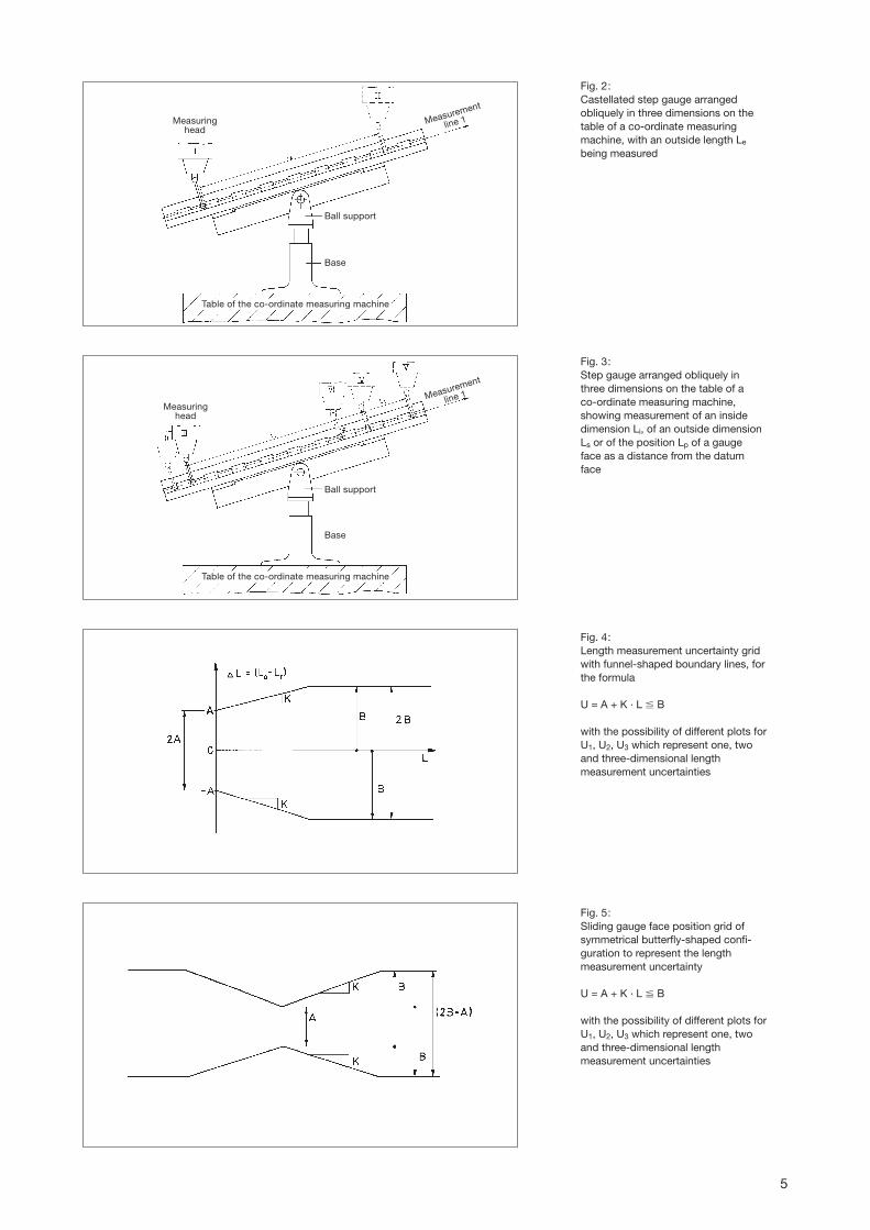
Fig. 2:Castellated step gauge arrangedobliquely in three dimensions on thetable of a co-ordinate measuringmachine, with an outside length Le
being measured
Fig. 3:Step gauge arranged obliquely inthree dimensions on the table of aco-ordinate measuring machine,showing measurement of an insidedimension Li, of an outside dimensionLs or of the position Lp of a gaugeface as a distance from the datumface
Fig. 4:Length measurement uncertainty gridwith funnel-shaped boundary lines, forthe formula
U = A + K · L � B
with the possibility of different plots forU1, U2, U3 which represent one, twoand three-dimensional lengthmeasurement uncertainties
Fig. 5:Sliding gauge face position grid ofsymmetrical butterfly-shaped confi-guration to represent the lengthmeasurement uncertainty
U = A + K · L � B
with the possibility of different plots forU1, U2, U3 which represent one, twoand three-dimensional lengthmeasurement uncertainties
Measuringhead
Measurement
line 1
Table of the co-ordinate measuring machine
Ball support
Base
Measuringhead
Measurement
line 1
Table of the co-ordinate measuring machine
Ball support
Base
5
AccessoriesThe range of accessories available which are neededfor use with the step gauge, such as swivel support,and base allows the gauge body to be mounted on theco-ordinate measuring machine in such a way as to befree of torsion. A support of this kind produces a par-ticularly stable connection between the step gauge andthe table of the co-ordinate measuring machine (Fig. 7,9 and 10).The combination of the step gauge and its accessoriesproduces a complete system for making an overallcheck on the co-ordinate measuring machine.One particularly important point is that the procedureof checking the co-ordinate measuring machine can becarried out fully automatically under computer control.
TraceabilitySince the acceptance or refusal of a co-ordinate mea-suring machine may depend on the outcome of thelength measurement uncertainty test, it is advisablealways to use officially calibrated testing equipment inorder to avoid unpleasant surprises and wrong inter-pretations. The KOBA-step step gauge is available withboth DKD calibration-certificate (German CalibrationService-DKD) and Works Calibration.The length measurement uncertainties which can cur-rently be achieved with the step gauge areDKD: U = 0,12 µm + 0,6 · 10–6 · L) (length)Works Calibration: U = 0,3 µm + 0,8 · 10–6 · L) (length)
RecalibrationAs is normal with all measurement standards, theKOBA-step step gauge should be recalibrated after acertain period. We recommend the following recalibra-tion intervals:First recalibration after one to two years and each suc-cessive recalibration after two to three years.
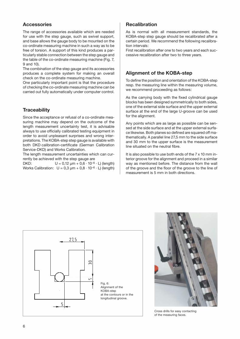
Alignment of the KOBA-stepTo define the position and orientation of the KOBA-stepresp. the measuring line within the measuring volume,we recommend proceeding as follows:
As the carrying body with the fixed cylindrical gaugeblocks has been designed symmetrically to both sides,one of the external side surface and the upper externalsurface at the end of the large U-groove can be usedfor the alignment.
Any points which are as large as possible can be sen-sed at the side surface and at the upper external surfa-ce likewise. Both planes so defined are squared off ma-thematically. A parallel line 27,5 mm to the side surfaceand 30 mm to the upper surface is the measurementline situated on the neutral fibre.
It is also possible to use both ends of the 7 x 10 mm in-terior groove for the alignment and proceed in a similarway as mentioned before. The distance from the wallof the groove and the floor of the groove to the line ofmeasurement is 5 mm in both directions.
Fig. 6:Alignment of the KOBA-step at the contours or in thelongitudinal groove.
Cross drills for easy contacting of the measuring faces.
6
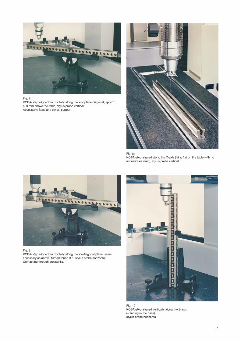
Fig. 7:KOBA-step aligned horizontally along the X-Y plane diagonal, approx.500 mm above the table, stylus probe vertical.Accessory: Base and swivel support.
Fig. 8:KOBA-step aligned along the X-axis (lying flat on the table with noaccessories used), stylus probe vertical.
Fig. 10:KOBA-step aligned vertically along the Z-axis (standing in the base), stylus probe horizontal.
Fig. 9:KOBA-step aligned horizontally along the XY-diagonal plane, same accessory as above, turned round 90°, stylus probe horizontal;Contacting through crossdrills.
7

Fig. 11:KOBA-step vertically orientated along the Z-axis (standing in the base) stylus probe horizontal (not shown).In this alignment also suitable to check height gauges.
Fig. 12:KOBA-step aligned vertically for checking height gauges.
8
Size 1 Size 2
Practical Use
Practical experience in using the KOBA-step step gau-ge for checking the accuracy of co-ordinate measuringmachines and assessing and interpreting the resultshas demonstrated the usefulness and potentially highinformation yield of the “length measurement uncer-tainty“ method. The advantage lies in the fact that themeasurement is carried out at precision gauge facesusing the normal gauging procedure and in the main,the machine manufacturer's standard processing soft-ware. Since the unidirectional and bi-directional gau-ging of inside and outside dimensions, dimensions bet-ween similarly orientated surfaces, and successive di-mensions from a given point occur even in the routinemeasurement of work pieces and since the measure-ments which have been obtained can be correlated withone another as desired even after the event, it is goodidea to make full use of the opportunities offered by thestep gauge. What is more, a series of measurements atall the gauge faces in succession provides a large amo-unt of interrelated information and requires only a shorttime for measurement.Since the length measurement uncertainty characteri-stic very much depends on the geometry of the co-ordinate measuring machine, the lines along whichmeasurements are made should be as follows:
– 3 to 4 measurement lines which are diagonal in threedimensions (i.e. along the diagonals of an inscribedcube – at a gradient of approximately 35° – or alongthe diagonals of the cuboid representing the mea-sured space).
– 2 diagonal lines of measurement in each co-ordina-te plane (i.e. along the diagonals of a square – at agradient of 45° – or the diagonals of a rectangle).
– At least one line of measurement parallel to each co-ordinate axis.
At least 18 suitable lines of measurement have to beselected in order to arrive at a complete definition ofthe 18 geometrical cuboid characteristics of the entiremeasurement volume.
It has to be stressed in particular that reliable mea-surement results for the complex system cannot beachieved unless the stylus probes are included.Checking of the co-ordinate measuring machine with-out mechanically contacting, i.e.: without using aprobe, will therefore not result in an comprehensivestatement about the accuracy of the measuring ma-chine.
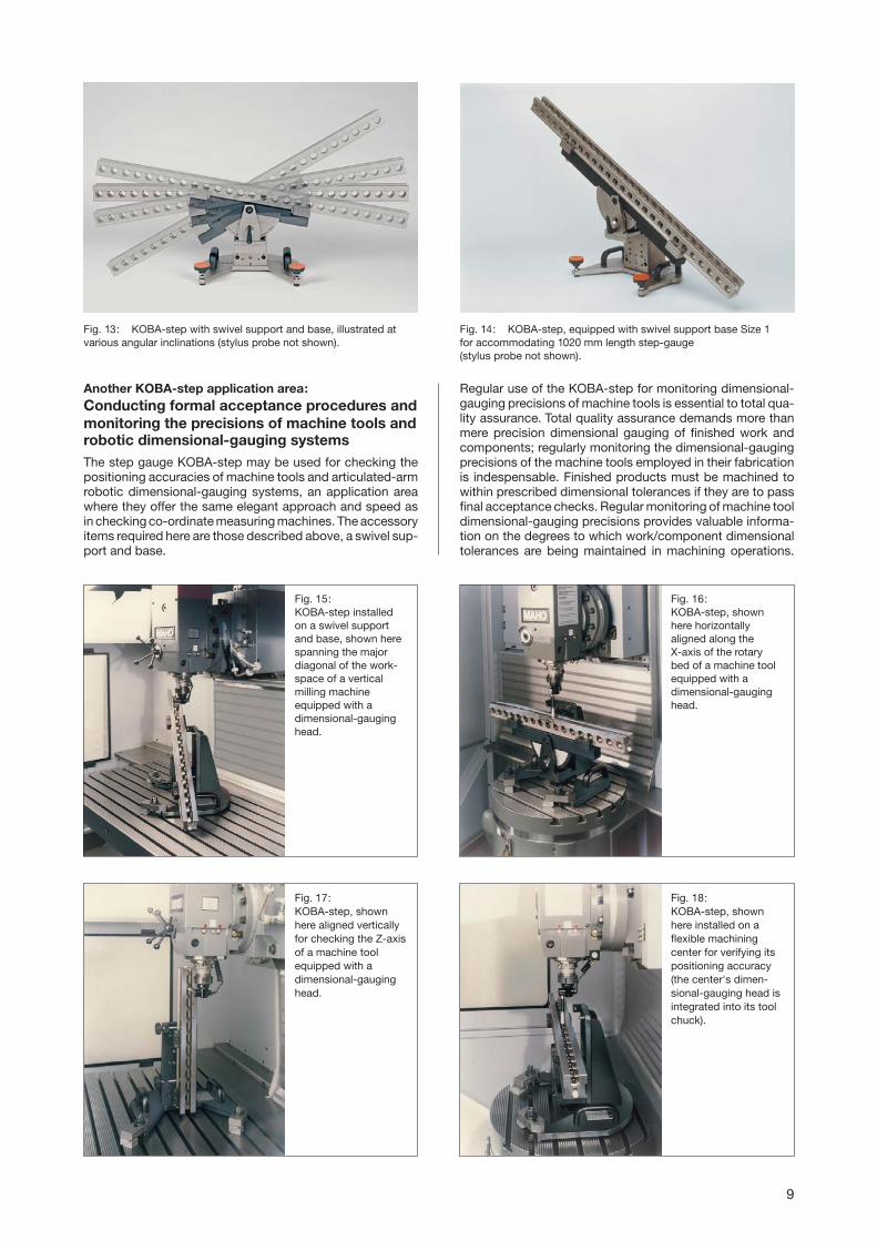
Fig. 13: KOBA-step with swivel support and base, illustrated at various angular inclinations (stylus probe not shown).
Fig. 14: KOBA-step, equipped with swivel support base Size 1for accommodating 1020 mm length step-gauge (stylus probe not shown).
Fig. 15: KOBA-step installedon a swivel supportand base, shown herespanning the majordiagonal of the work-space of a verticalmilling machineequipped with adimensional-gauginghead.
Fig. 16: KOBA-step, shownhere horizontallyaligned along the X-axis of the rotarybed of a machine toolequipped with adimensional-gauginghead.
Fig. 17: KOBA-step, shownhere aligned verticallyfor checking the Z-axisof a machine toolequipped with adimensional-gauginghead.
Fig. 18: KOBA-step, shownhere installed on aflexible machiningcenter for verifying itspositioning accuracy(the center's dimen-sional-gauging head isintegrated into its toolchuck).
9
Another KOBA-step application area:Conducting formal acceptance procedures andmonitoring the precisions of machine tools and robotic dimensional-gauging systemsThe step gauge KOBA-step may be used for checking thepositioning accuracies of machine tools and articulated-armrobotic dimensional-gauging systems, an application areawhere they offer the same elegant approach and speed asin checking co-ordinate measuring machines. The accessoryitems required here are those described above, a swivel sup-port and base.
Regular use of the KOBA-step for monitoring dimensional-gauging precisions of machine tools is essential to total qua-lity assurance. Total quality assurance demands more thanmere precision dimensional gauging of finished work andcomponents; regularly monitoring the dimensional-gaugingprecisions of the machine tools employed in their fabricationis indespensable. Finished products must be machined towithin prescribed dimensional tolerances if they are to passfinal acceptance checks. Regular monitoring of machine tooldimensional-gauging precisions provides valuable informa-tion on the degrees to which work/component dimensionaltolerances are being maintained in machining operations.

Standard nominal lengths
Contents of sets
10
nominal lengthmm
420
620
1020
1540
2020
22
32
52
78
102
480
680
1080
1600
2080
6.5
9.5
15.0
23.0
30.0
number ofgauge faces
overalllength
weightkg
The nominal length of a step gauge is the distance from the first gauge face to the last gauge face.Special sizes on enquiry, at present available with length up to 2500 mm.
Set N° 5/420
Contents: 1 off Step gauge, nominal length 420 mm2 off fixing clamps1 off swivel support for 420 mm1 off Base size 1
housed in storage box
housed in storage box
housed in storage box
housed in storage box
housed in storage box
housed in storage box
Following characteristicsidentical for all lengthslisted:
Cross-section of holder:55 x 55 mm
Cross-section of cylin-drical gauge blocks:10 mm diameter
Length of castellations:20 mm
Space between castel-lations:20 mm
Weight
26 kg
26 kg
30 kg
31 kg
31 kg
30 kg
38 kg
38 kg
30 kg
Set N° 5/620
Contents: 1 off Step gauge, nominal length 620 mm2 off fixing clamps1 off swivel support for 620 mm1 off Base size 1
Set N° 5/1020
Contents: 1 off Step gauge, nominal length 1020 mm2 off fixing clamps1 off swivel support for 1020 mm1 off Base size 1
Set N° 5/1540
Contents: 1 off Step gauge, nominal length 1540 mm2 off fixing clamps1 off swivel support for 1540 mm1 off Base size 2
housed in storage box
with 2 transport cases
Weight
38 kg
82 kg
Set N° 5/2020
Contents: 1 off Step gauge, nominal length 2020 mm2 off fixing clamps1 off swivel support for 2020 mm1 off Base size 2
housed in storage box
with 2 transport cases
Weight
45 kg
96 kg
The step gauge KOBA-step can be aligned with allrequested orientations – horizontally, vertically, diago-nally and obliquely. With the swivel support angles can
be set from –50° to +50° in steps of 5°. The base maybe used as a holder for the swivel support as well asfor the vertical alignment of the KOBA-step.
�
�
�
Where individual components are not required thecompartments provided for them are left empty.
�
�
�
�

11
Copy of a DKD-CalibrationCertificate for astep gauge KOBA-step
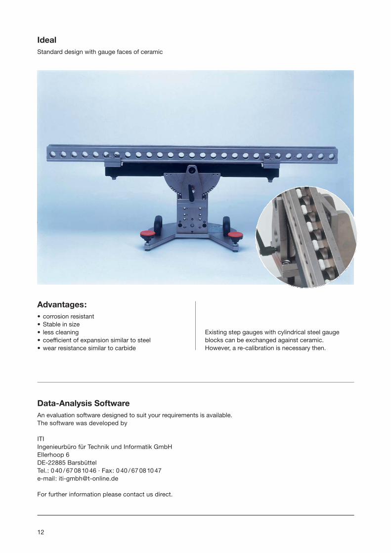
IdealStandard design with gauge faces of ceramic
12
Advantages:• corrosion resistant• Stable in size• less cleaning• coefficient of expansion similar to steel• wear resistance similar to carbide
Existing step gauges with cylindrical steel gaugeblocks can be exchanged against ceramic. However, a re-calibration is necessary then.
Data-Analysis SoftwareAn evaluation software designed to suit your requirements is available.The software was developed by
ITIIngenieurbüro für Technik und Informatik GmbHEllerhoop 6DE-22885 BarsbüttelTel.: 0 40 / 67 0810 46 · Fax: 0 40 / 67 0810 47e-mail: [email protected]
For further information please contact us direct.
13
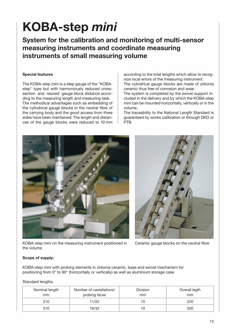
KOBA-step miniSystem for the calibration and monitoring of multi-sensormeasuring instruments and coordinate measuringinstruments of small measuring volume
Special features
The KOBA-step mini is a step gauge of the "KOBA-step" type but with harmoniously reduced cross-section and resized gauge block distance accor-ding to the measuring length and measuring task.The methodical advantages such as embedding ofthe cylindrical gauge blocks in the neutral fibre ofthe carrying body and the good access from threesides have been maintained. The length and distan-ces of the gauge blocks were reduced to 10 mm
Scope of supply:
KOBA-step mini with probing elements in zirkonia ceramic, base and swivel mechanism for positioning from 0° to 90° (horizontally or vertically) as well as aluminium storage case
Standard lengths
Nominal length Number of castellations/ Division Overall legthmm probing faces mm mm
210 11/22 10 220
310 16/32 10 320
Ceramic gauge blocks on the neutral fibreKOBA-step mini on the measuring instrument positioned inthe volume
according to the total lengths which allow to recog-nize local errors of the measuring instrument.The cylindrical gauge blocks are made of zirkoniaceramic thus free of corrosion and wear.The system is completed by the swivel support in-cluded in the delivery and by which the KOBA-stepmini can be mounted horizontally, vertically or in thevolume.The traceability to the National Length Standard isguaranteed by works calibration or through DKD orPTB.

For the first time, this gauge block combines theadvantages which step gauges offer the user with theability to meet the stringent metrological demandswhich a precision measurement standard has to meet:
� Available with various standard nominal lengths(210, 310, 420, 620, 1020, 1540 and 2020 mm) witheven steps (castellation/gap = 10/10 mm, from420 mm = 20/20 mm), also with different standardlengths and uneven steps (however, castellation =10 mm, from 420 mm = 20 mm) for an optimaladjustment to the measurement task.
� Stainless finish guaranteed by special surfacetreatment.
� The gauge faces used are the specially machinedend faces of cylindrical gauge blocks which are insetsolidly into position in a groove by a special pro-cess.
� Gauge faces lapped for correct sensing.
� Carrying body specially aged for longterm stability.
� Solid connection between the cylindrical gaugeblocks with gauge faces and the carrying body.
� Cylindrical gauge blocks deeply inset to protectthem against damage, length 20 mm.
� Gauge faces conically reduced to 5 mm diameter,hence easy to clean.
� The centres of the gauge faces are located on thefibre of the carrying body which is neutral in ben-ding. As a result changes in bending stress due todifferent horizontal or inclined or vertical orientati-ons have an effect on the distances between thegauge faces which is so small that it can be ignoredcompletely.
� Because of the configuration adopted, the bendingcharacteristics in the two principal planes are iden-tical, and it is therefore equally possible for thegauge block to be orientated with the groove facingupwards (e.g. for vertical quills) or to one side (e.g.for horizontal quills) or downwards (e.g. for under-floor measuring machines with vertical quills ope-rating from below). The measurements to determi-ne the position of the carrying body in space can becarried out on the precision-machined rectangulargroove.
� The longitudinal grooves in the side faces allow awide variety of orientations and mounting methodson the table of the machine.
� The material of the carrying body determines its ex-pansion characteristics (α = 11,5 · 10–6/°C).
� The accuracy required is of a standard not achie-ved hitherto and is ensured by the use of a speciallaser interferometer comparator which gives theprecise position of each gauge face. The numericalvalue (Actual value according to the Calibrationchart) representing the position is not generally awhole-number decimal and qualifies immediatelyto direct the co-ordinate measuring machine andresp. for the evaluation of the length measurementuncertainty.
� Additional reliability in everyday use because thelength of each individual cylindrical gauge block isknown and does not vary and must be re-measu-red accurately by the co-ordinate measuring ma-chine itself with the step gauge in any position andorientation.
� Cross drills between the castellations for easysensing of the measuring faces.
14
A brief review
of the KOBA-step step gauge
References:
[1] VDI/VDE 2617 Part 1, 2.1, 5 Accuracy of Co-ordinate Measuring MachinesBeuth-Verlag
[2] VDI/VDE 2617 Bl./Part 1, 2.1, 3 German-English EditionAccuracy of Co-ordinate measuring machinesBeuth-Verlag
[3] VDI-Bericht 529: Koordinaten-Meßtechnik,Verlag des Vereins Deutscher Ingenieure –Düsseldorf, 1984
[4] CMMA Genauigkeits-Spezifikationen fürKoordinaten-Meßgeräte (1982)Co-ordinate measuring machine manufacturersassociation c/o BCM, 27 a Old Gloucester Street,London, WC IN 3XXX
[5] H.-H. Schüßler – Meßtechnische Beurteilung von Prüfkörpern und Koordinaten-Meßgerätenanhand von Streckenmessungen, Rechteck- und Quader-KennwertenTechnisches Messen tm, 52. Jahrgang,Heft 10/1985, Seiten 353–366
[6] M. Weck – Werkzeugmaschinen Band 4,Meßtechnische Untersuchung und BeurteilungVDI-Verlag Düsseldorf