knight - compassmodel.netcompassmodel.net/.../knight_600e_manual.pdf · reassembly following ......
TRANSCRIPT

KNIGHT600EMore Power Better Efficiency
Instruction Manual
* .** .**** - .* +/- .
* .* .* .* .
* - .
Hardened hollow main shaftDual pin tail rotor pitch mechanismThrust bearings built in tail gripsCCPM swash controls
uick to buildHardcore 3D of boxFully Ball Raced
12 5 degree collective pitch range forextreme 3D
Extra tough frame designHigh Torque Brushless MotorHigh efficiency direct belt drive systemHigh CG design
Push pull
Q
control
Gear Ratio 1 8 7 4 8
Blade Length 600 620mm
Take off Weight 3 3kg
: : :
: -
- : .
. .
As we continue to improve our products. This manual may not reflect all recent product amendments. Please refer to thereceived product and check our website:��������,�� ���,�����������: .����,�� !.
www.compassmodel.comwww compassmodel com. .
*"#$%&'*()0123456*2789;<'=* >?@A,BC�D*EFGHIJ*KLMNOPRST UVW<*SXY'=Z[*+/- . \]734^_*`a&bc6*`]d<Kefg*hijk@A*hl%mn*opq>?@A
CCPM
3D
12 5
jkr: : . : .
]7: -
sUlt: .
1 8 7 4 8
600 620mm
3 3kg

Introduction ��Thank you for choosing the Knight 600E and welcome to Compass Model. The Knight 600E has been carefully designed to
offer out standing flight performance and includes many innovative features along with proven components to provide you
with a model which is accurate, durable and agile. The 600E was developed with input from leading pilots to meet the
requirements of the most demanding aerobatic flight styles, both now and in the future. The control system incorporates a
closed loop push-pull system for all swash plate linkages and optimum ccpm geometry to ensure unrivalled control accuracy
and rapid head response. Similarly, the frame lay out has been designed to create an extraordinarily rigid platform which is
both durable and further improves control accuracy. This compact layout features light weight and raised centre of gravity
Please read the complete manual before assembly, which has been designed to enable you to get the best from your model -
please take careful note of all precautions and assembly tips. Please also keep the manual as a reference for part numbers and
reassembly following maintenance.
KNIGHT600E
KNIGHT600E 3D CCPM
.
����������. ����������������������� �.!��"#���$, %&'()*#+- /0.12345678,9:;,<=>.?@A�BC DEF12GH,IJKL�M,NOPQR.A�+STU%VW@. %XYZU,J[,12\]^_`ab��ccd.efghijk�lmno�.
In
Power Battery
GyroRegulator
BEC
���������� �
/Radio For R C heli models and
Power batteries
�������������
��� �,�����,4 BEC�� ( )
��.
�
This model requires radio forR C heli with 4 servos 1 Gyroand 1 BEC/ , ,
.
���
qUWr
stu
�������� �����,������
Necessary Items Not Included In this Package
Mishandling due to failure to follow these instructions may result in damage personal injury or danger, .vwxyijz0{|}O:~,}O����,����.
Blue Thread lock should be applied.x��A���t����
The Meaning of Symbols ����
ESC ���

Obtain assistance from experienced pilots������
Certain level of skill is required to operate R C helicopter The Guidance provided by experienced pilots is
valuable and sometimes necessary for assembly tuning and flights It is also recommended that you practice
with a computer based flight simulator
/ ., , .
.���������� ����.����������������.��� !,"#,�$%& '(�)*+� .-0123�456��78�9:;<=&>?@>.
Keep a safe distance when operating����
During operation the main blades and tail blades on a r c helicopter spin at a very high rate of speed The
blades are capable of inflicting serious bodily damage or injury to yourself or others Keep the model at a safe
distance away from yourself and other people Never take your eyes off the model whenever the blades are
spinning
, / ..
..
�����ABCD,EFGHFGIJFK,LCMNOPQRSTUVWXYZ[\]^._C,���`abc+defghi,jklm;nBo�pq.
Warning ���This radio controlled helicopter model is not a toy.
Manufacturer and Sellers assume no responsibility for using and operating this product..
�����-)rs,t�uv�� ����.w ,45P��xyz{UVWX|�}~,NOPQRSTYZ,[\]^.�����6���,����fg.�U�,������45���w ,��,���45xyUV }~PYZ�����. ������,6���x������45& fg��.
� 0123_¡��$%¢£�¤¥ (§¨ ). ��ª��$%¢£�«¬c )®¯°w±。 {³{´µ¶{ ·¸ ,-¹¡¡º��$% d»。_¡
¼½ ¾¿Àz{�Á{³Â¡ ÃÄ ��ÅÆ�ÇÄ:
It is a sophisticated piece of equipment for hobby use only.
Improper operation or assembly of this product can cause serious injury or death for both operator and spectators.
The customer must
take full responsibility for the safe operation of this product
AMA INFORMATION
Academy of Model Aeronautics
Academy of Model Aeronautics
We strongly encourage all prospective and current R/C aircraft pilots to join the Academy of Model Aeronautics. The AMA
is a non-profit organization that provides services to model aircraft pilots. As an AMA member, you will receive a monthly
magazine entitled , as well as a liability insurance plan to cover against possible accident or injury. All
AMA charter aircraft clubs require individuals to hold a current AMA sporting license prior to operation of their models.
For further information, you can contact the AMA at:
5151 East Memorial Drive
Muncie, IN 47302
Academy of Model Aeronautics AMA AMA
AMA
AMA AMA
5151 East Memorial Drive
Muncie, IN 47302
Model Aviation
Model Aviation
This
product is not recommended for use by children.
Safety Notes ����
Operate in safe areas.�����
Do not fly r c helicopter model near buildings high voltage cables trees or other obstacles Do not fly r c
helicopters in poor weather such as rain snow or fog Do not fly r c helicopters over crowds of people cars or
other property Flying field should be a smooth clear and flat field
/ , , . /, . / ,
. , .��$%jÉi2ÊË,IÌÍ,Î�ÏQÐÑË.���Ò,Ó,ÔÕxÖ×ØÙ$%.���RÚ,ÛÜ�2Ê&Ý$%.$%Þß���à#,áâ,�ãä .
Do not expose to rain or moisture������
R c helicopter models are comprised of many electrical components Water moisture or other contaminants can
cause failure or malfunction of those components and result in crash s or accidents
/ . ,
, .;n���åæ¡çè9éêë.�ÉiìíîïCðñØ}ò9éêëUVó».
e
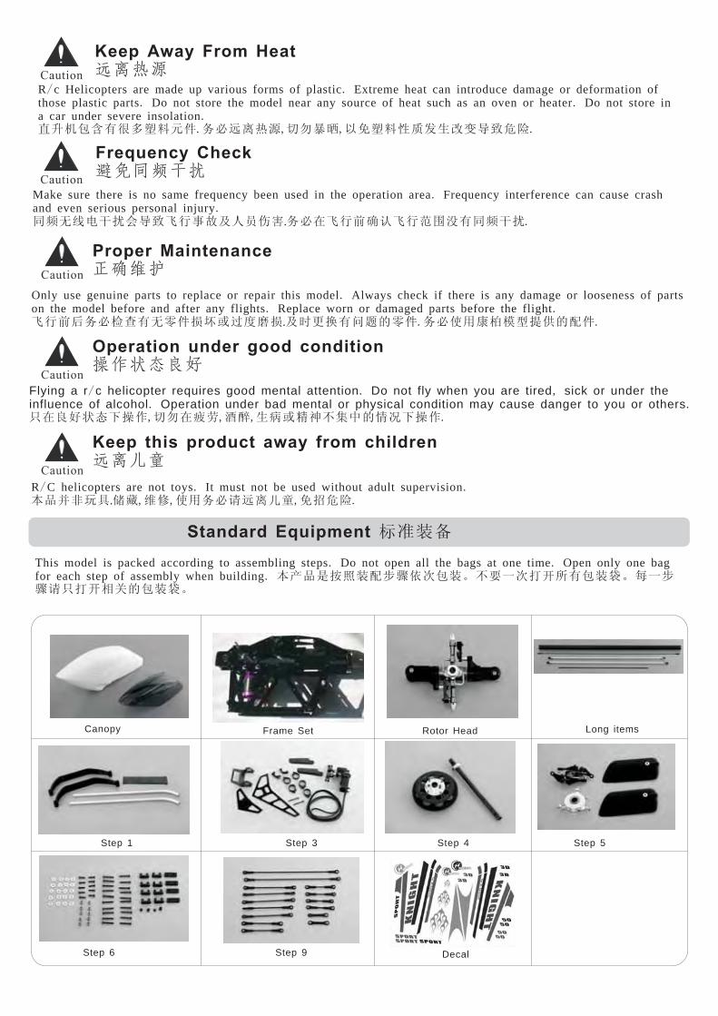
Proper Maintenance����
Only use genuine parts to replace or repair this model Always check if there is any damage or looseness of parts
on the model before and after any flights Replace worn or damaged parts before the flight
.
.. .
���������� ����� ���������.�������� !�"�.
Operation under good condition����
Flying a r c helicopter requires good mental attention Do not fly when you are tired sick or under theinfluence of alcohol Operation under bad mental or physical condition may cause danger to you or others
/ . ,. .
#$%&'()*+,-0$12,34,56�789:;�<=)*+.
Keep this product away from children�� �
R C helicopters are not toys It must not be used without adult supervision
.
/ . .>?@ABCDE,FG,����HIJKL,MNOP.
Standard Equipment QRST
This model is packed according to assembling steps Do not open all the bags at one time Open only one bag
for each step of assembly when building
. .. >U?VWXS"YZ[\]S。9_`\abc]Sd。e`Y
ZH#abfg�]Sd。
Canopy Frame Set Rotor Head
Step 1 Step 3 Step 4 Step 5
Step 6 Step 9 Decal
Long items
Keep Away From Heat����
R c Helicopters are made up various forms of plastic Extreme heat can introduce damage or deformation of
those plastic parts Do not store the model near any source of heat such as an oven or heater Do not store in
a car under severe insolation
/ .. .
.hij]klmnop�.��IJqr,-0st,uMnovwx5yz{|OP.
Make sure there is no same frequency been used in the operation area Frequency interference can cause crash
and even serious personal injury
.
..
}~�����{|�����������$����������}~��.
Frequency Check������

When switching the R/C system ON or OFF, always proceed in the following order:
When switching ON:
Place the throttle control stick into motor stop position.
Turn on the transmitter.
Turn on the receiver.
Connect the motor battery.
Operate your model.
When switching OFF:
Turn off the motor (place the throttle control stick into motor stop position).
Wait until the rotor head has stopped spinning.
Disconnect the motor battery.
Turn off receiver.
Turn off transmitter.
���������� ��������:
��������:��� �����.�����.�����.������.��� .
!"�����:��� �����.#$%&'()�.*+����.!"���.!",-�.
ORDER OF SWITCH ON OFF/ ��/!"01

Step 1 Landing Gear Installation �����
Radio Tray ���
Skid Tube�
M3 Washer
��
Landing Gear Struts
���
M3 Nylon Nuts
���
M3x10 Bolt
���
���� �-Frame Set Pre assembled
in Factory
M3x22 Socket HeadBolt ����
M3 Washer x4
M3 x4��
M3 Nylon Nut x4M3 x4����
M3x10 Bolt x 2M3x10 x2����
M3x5 Set Screw ��
M3x22 Socket Head Bolt x 4M3x22 x4����
M3x5 Set Screw x5M3x5 x5��
Step 2 Motor Pinion Installation �����&
M3x22 Socket Head Bolt x 4M3x22 x4����
M3x22 Socket Head Bolt����
Brushless Motor����
Assembling ��* .������ ���!"#$%&'()
* .��+,/!"0$%&'()* - , . 23456789�� �:;��<=>?89��.
Always apply blue Loctite when fixing Bolts on Metal parts
Always apply green Loctite where Bearings fit in Metal partsDo not over tight Self Tapping Bolts into plastic otherwise plastic part could be damaged
..

M3x15 SocketHead Bolt ����
M3 Nylon Nut����
M3 Nut ��
M3 Nylon Nut����
M3x30 Socket HeadBolt ����
M3 Washer�
M3x40 SocketHead Bolt ����
M3x40 Socket HeadBolt ����
M3x12 Socket HeadBolt ����
M3 Nut ��
M3 Nylon Nut����
M3x20 Socket HeadBolt ����
M3
Washer�
Crimping damages the tensile cords andwill result in premature failure.�� ,������.
There are 2 grooves in the Boom. There is a lug inside theTail Gear Case. Line up the longer groove with the lugwhen assembling.���,���������� !"#�$�.
Drill here %&'(
Lug $�Longer Groove ��
Tail Boom ��Gear Case � !"
To avoid any tail gear case rotation drill a hole in theboom through the guide hole on the tail gear case andfix it using a bolt.)*+� !"-/'(%&,0���12�34��56.
Step 3 Tail Boom, Tail Boom Brace & Tail Rotor Installation �7���
M3x12 Socket Head Bolt x2M3x12 X2����
M3x16 Socket Head Bolt x8M3x16 x8����
M3x40 Socket Head Bolt x6M3x40 x6����
M3x15 Socket Head Bolt x2M3x15 x2����M3 Washer x4
M3 x4��
M3 Nylon Nut x8M3 x8����
M3 Nut x4M3 x4��

Check tail drive belt direction.�������
Check tail rotor direction.(Top rotor blade moves torear)����
Step 4 Main Gear Installation � ���
M3x25 Socket Head Bolt xM3x25 x1����
1
M3x10 Socket Head Bolt x 1M3x10 x1����
M3 Nylon Nut x1M3 x1����
�������� !��"�#$%&�.
M3 Nylon Nut����
M3x25 SocketHead Bolt
M3x10 SocketHead Bolt ����
Mast Collar����
If the tail rotor rotates incorrectly, simply pull out the main shaft and twist the belt in the other direction'���($)����#,�*�+��,(-$)/.(����02,3����4���56.
Note The Mast Collar isinstalled underneath theupper bearing block
:
.�����7�8�9;%�.
Make sure mast lock collar istightened securely onto the mast.Double-check to make sure themast lock collar is properly seatedonto the mast and main shaft cannot move up or down.
����
Rotate the tail drive belt 90° to the right beforemounting it onto the main pulley. It is extremelyimportant to install the belt in the properdirection to insure correct rotation of the tailrotor blades.
90�����#<= >。
Upper BearingBlock �9;

Step 5 Rotor Head, Washout & Swashplate Installation ������
M3 Nylon Nut x1M3 x1��
M3x22 Socket Head Bolt x1M3x22 x1���
M3x3 Set Screw X2M3x3 x2 �
M3x3 Set Screw �
Paddle���
M3x22 Socket Head Bolt���
Washout Set������
Swash Plate���
Main Shaft��
8x16x5 Bearing��
8x16x5 Thrust Bearing����
8x16x5 Bearing��
Main grips are factory preassembled, in case of reassembling;be sure to note correct placement of large/small I.D. washersduring assembly.�� !"#$��%&,'()*+-./0,1-.��2345�����6�78.
Thrust Bearing Direction �����6�:;<=>?
Main Grip ��
@A� @AB
Adjust so that each side has exactly the same length CDEFGHI
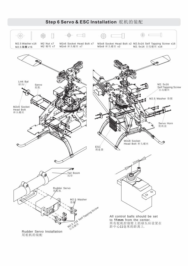
Step 6 Servo & ESC Installation �����
Link Ball��
M2x6 SocketHead Bolt��
Servo��
M2 5x16Self Tapping Screw.
��
M2 5 Washer. �
Servo Horn���
M2 5 Washer x16
M2 5 x 6
.
. �� 1
M2 Nut x7M2 x7�
M2x6 Socket Head Bolt x7M2x6 x7��
M2 5x16 Self Tapping Screw x16
M2 5x16 x16
.
. ��
Tail Boom��
Rudder Servo���
M2
5x16
Self Tapping Scre
w
.
��
M2 5 Washer.
�
11mm
Rudder Servo Installation������
All control balls should be setto from the center
11
.������������������ !��"�.
11mm
M3x8 SocketHead Bolt ��
ESC#$%
M3x8 Socket Head Bolt x2M3x8 x2��

Step 7 Electronic Devices Arrangement �������
ESC���
Power Battery���
Receiver���
Aileron Servo����
Gyro���
Pitch Servo����
Elevator Servo����
Power Battery���
Gyro��
Aileron��
Elevator��
ESC Signal���
Rudder���
Pitch��
HitecFutaba JR
Ch1
Ch2
Ch3
Gyro Gain���
Ch5
Ch4
Ch5
Ch2
Ch3
Ch1
Aux2
Ch4
Aux1
Regulator
Esc Signal Line ����
ES
Co
utp
ut
toM
oto
r
BEC��
Please check first your radio and ESC manuals before connecting these electronic devices as shown below.� ����!�"#$%&'()*��+,-.
Receiver�/�

Main Grip ��� Washout Arm�����
Phasing Control Ring �Boom �
Parallel tothe Boom�� ��
Gets the right phasing adjustment byturning the phasing control ring untilthe washout arms and main gripswould be parallel to the tail boom.
Main Grips���
Washout Arm
Boom �
Phasing Block�
Step 8 Phasing Control Ring Adjustments ����
Step 9 Linkage Length Adjustments ����
Lin
ka
ge
Le
ng
th����
The following linkage lengths indications are basic values which could vary depend onused servos.Some fine adjustments are still needed in following setup steps.�������������� .!"� ����#$%&'(,)*&+-/012&3456.
��789':;��9<=�����>���?@��A� .
26 5mm x2.
59mm x2
43mm x2
39mm x2
64 5mmx2.
147mm x2

73mm x2
Ball Link Sizing Tool������
If Ball Links are too tight to resize tight ball links only use theCompass Model ball link sizing tool (E-XQT-01)The Ball Link Sizing Tool is very sharp use it with cautiondo not over size Ball Links and do not adjust with pliers
,
, ,, .
�������,��� ����������������.�������,������ !.
Do not apply plier to resize Ball links Plierscould cause hidden damage to ball links andhence result in failure when operation
.
.�"���������,��#���������$%&'()*+-/.
Step 10 Radio Setting 012�34
Normal ID1 ID2 Autorotation JR Futaba
Sport 3D Swash Type SWH
High Pitch 9~10 10 12 12 S3 120 SR3
Hovering 5~5.54~5
0 N/A Aile Elev Pitch
Low Pitch -4 -6 -12 -7 65% 65% 65%
Normal ID 1 Auto RotationID 2
Normal ID 2ID 1 Auto Rotation
100%
75%
50%
25%
0%
1 2 3 4 5
100%
75%
50%
25%
0%
1 2 3 4 5
100%
75%
50%
25%
0%
1 2 3 4 5
100%
75%
50%
25%
0%
1 2 3 4 5
100%
75%
50%
25%
0%
1 2 3 4 5
100%
75%
50%
25%
0%
1 2 3 4 5
100%
75%
50%
25%
0%
1 2 3 4 5
100%
75%
50%
25%
0%
1 2 3 4 5
For any radio setup please refer to your radio instructions first.The data's shown above provide some general suggestions for radio setting. This informationvaries according to types of main blades, motor, pinion gear and battery pack. Adjustment has tobe made during the actual flight. �634789:,;<=>?@ABCD+EF.
Pitch Curve GHI
Throttle Curve JKIL
Pitch Setting GHMN Swash Type SettingOPQRST34

Turn on the radio position the heli tail point to yourself, .Make sure radio is set to 120 degree CCPMmode Move the stick and check the reaction of the Swash Plate Throttle and Tail Pitch Plate Adjustradio settings accordingly
120 ccpm
. , ..
�����,����� ��.�������� � ��. ���������� !"#�$%&'.
Step 11 Servo Direction Check "( )��
Aileron Check *+��
Mod 1 Mod 2Swash Plate Reaction
-/012
Tilt Left34
Elevator Check �5��
Tilt64
Forward
Tilt Right74
Tilt84
Backward
Rudder Check "�� Tail Pitch Plate9:0
Slide left3;
Slide Right7;
Pitch Check 9:��
Swash Plate-/0
Ascent <�
Descent �5
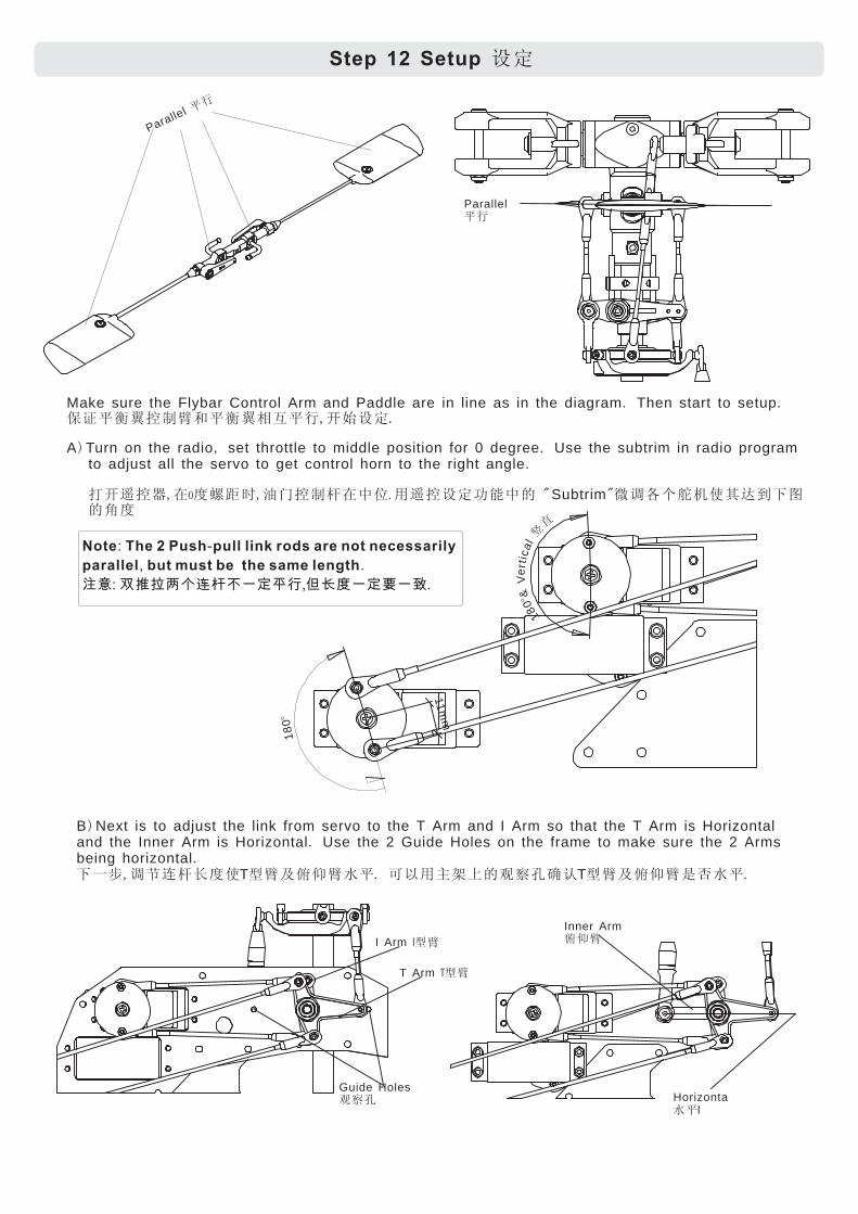
Step 12 Setup ��
Make sure the Flybar Control Arm and Paddle are in line as in the diagram Then start to setup
A Turn on the radio set throttle to middle position for 0 degree Use the subtrim in radio programto adjust all the servo to get control horn to the right angle
Subtrim
. .����������� ��,����.
) , ..
�����,� ����,������� ������ �! " "#$%&'(*+-/01!2�
0 .
Parallel ��
Parallel��
18
0°
180°&
Ve
r tic
al4
5
Note The 2 Push pull link rods are not necessarily
parallel but must be the same length
: -
, .
��: �������� �,��������.
B Next is to adjust the link from servo to the T Arm and I Arm so that the T Arm is Horizontaland the Inner Arm is Horizontal Use the 2 Guide Holes on the frame to make sure the 2 Armsbeing horizontal
T
).
.067,$89�:�* ;<=>?�. @A�BCD!EFGHIT;<=>JK?�.
I Arm ;I
T Arm ;T
Guide HolesEFG Horizonta
l?�
Inner Arm=>
11
mm

C Next adjust the links from T Arms to Swash
Plate to level Swash Plate A compass Swash
Plate Tool can be applied here as a guide
D Set the Washout Arms horizontal
)
.
.
�� �������� ������. ��
���������������.
) .
������ ���.
T
Washout Arm������
Horizontal��
06 0501 Swash PlateTool-�����
Swash Plate���
2°
Mix Arm �
Flybar�� �
E Set Mix Arm 2 downwards to Flybar) °
������� � ��.2°
F Install the main blade and set the Main
Blade to 0 pitch 2 Ball Links might need
to be cut shorter to get the right pitch
)
° .
.
����� ������ ���� !".#$%&,'()*+/+0123456��.
, 0°
7°90°90°
H At Rudder middle stick set Rudder Servo 90 degree to the tail
link And set Tail Blade to 7 pitch
90 7
) ,
. ° .
���� 789:����� �;,7�!"� �.
Cut 3<
G Carefully read the manual of ESC Brushless Motor Speed Controller Set up the ESC accordingly) ( ), .
!"#$%&�'*�+-/,13��4�'*.
: .
56: �'*���78.
Note Set the timing to Middle
Horizontal��

This Mark is only a guide please put the
canopy on the heli frame to obtain theexact position before drilling the hole
here
,
.
� ��������。�� �����
��������。
! �
Drill a hole on this mark.�������
Cut along this line���
Drill holes after checking correct position� ������。
Canopy window���
Canopy Dampner
�
�
�
�
�
M2
5x6
Self
tappin
g
.
.
�
�
�
�
S
c
r
e
w
M
2
5
x
6
Install Canopy Windowand Canopy Damper�����������
Step 13 Canopy Installation �����
Install the Canopyonto the helicopter.������
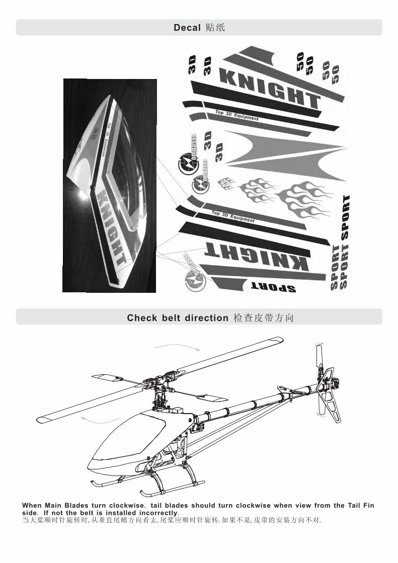
��Decal
When Main Blades turn clockwise tail blades should turn clockwise when view from the Tail Finside If not the belt is installed incorrectly
,. .
�������,�� ������,������.����,���������.
Check belt direction � ����

- �����Pre Flight Check
1 Ensure that receiver transmitter battery are fully charged2 Check all bolts and screws are tight
3 Repeat step 11 to check all Servo functions are correct4 Ensure Tail Gyro direction are correctly set
. & .����� ������.
. .�������������.
. . �� �� ��!"#$%'.
. + .��("�)�*�,/%�.11
Tail Moving Direction
(012
,/
Tail Blades
Rotation Direction
(3�4
12,/
5 Check that the Main Blades Paddles and Tail Blades are installed in the right direction
6 Check that there are no missing or damaged parts never fly with any damaged parts
7 Make sure all electronic devices are firmly fastened and connected
8 Before starting the motor make sure the IDLE switch is OFF and Throttle stick is in the lowposition IDLE
9 Only turn off the transmitter after turning off the receiver
. , .��63,789�(3�:;,/<=%�.. , .���>?@ABC�DE.F�GHIJKLM.NOP�Q�.. .�����RSET�U�VW,XYVW..
. �Z>[\]�^_�,�� `aab,cdefghijk.. .lhab��^mnab� �^.
Compass Model HK Limited( ) qrst(uv)�wxy. .www compassmodel com

Compass Model Hong Kong Ltd( ) .����(��)��
www compassmodel com. .
Knight 600E Instruction Manual
Copyright Dec 2007@ ,