kmu-100 instruction manual
TRANSCRIPT

PROCESSOR
Instruction Manual

2
Table of Contents TABLE OF CONTENTS........................................................................................................................................ 2
FCC COMPLIANCE STATEMENT ........................................................................................................................ 5
WARNINGS AND PRECAUTIONS ....................................................................................................................... 5
WARRANTY ...................................................................................................................................................... 6
STANDARD WARRANTY ..................................................................................................................................... 6 THREE YEAR WARRANTY .................................................................................................................................... 6
DISPOSAL ......................................................................................................................................................... 7
1. INTRODUCTION ....................................................................................................................................... 8
1.1 FUNCTIONS AND FEATURES ..................................................................................................................... 8 1.2 KMU-100 OPERATIONS ........................................................................................................................ 9
2. PRODUCT APPLICATIONS ....................................................................................................................... 10
2.1 VIDEO PRODUCTION AND POSTPRODUCTION ............................................................................................. 10 2.2 HIGH QUALITY SECURITY SYSTEMS .......................................................................................................... 11
3. CONNECTION TO THE KMU-100 – DV LINK ............................................................................................ 12
3.1 HARDWARE CONNECTION..................................................................................................................... 12 3.2 LAUNCHING DV LINK APPLICATION ......................................................................................................... 13
Tool Bar ................................................................................................................................................. 14 Available Networks area ....................................................................................................................... 15
4.1 APP WINDOW DESCRIPTIONS: CONNECTION TAB ...................................................................................... 18 Input Signal Configuration ...................................................................................................................... 21 Output Signal Configuration ................................................................................................................... 23
4.2 APP WINDOW DESCRIPTIONS: CHANNEL A AND CHANNEL B ......................................................................... 24 You can set a graphical background for the gray workspace of the Central Work Area, and the graphical
background should help you better position the frame windows. ............................................................ 25 Frame 1, 2, 3 and 4 Setting (Control) Area .............................................................................................. 25
4.3 TOOL BAR ........................................................................................................................................ 32
5. HOW TO OPERATE THE KMU-100 .......................................................................................................... 33
5.1 HOW TO OPERATE THE KMU-100 BY THE CONTROL SOFTWARE .................................................................... 33 5.2 HOW TO USE THE RMC-185 TO CONTROL THE KMU-100 .......................................................................... 39
5.2.1 HOW TO CONNECT THE RMC-185 KMU CONTROLLER AND KMU-100 4K MULTI-CAMERA
PROCESSOR ................................................................................................................................................ 39
6. INTRODUCTION OF THE RMC-185 CONTROLLER ................................................................................................. 40 6.1 NOTICES FOR DEVICE SETUP ......................................................................................................................... 40 6.2 CONNECTIONS AND CONTROLS OF THE RMC-185 ............................................................................................. 41 6.2.1 FRONT PANEL-KEYBOARD ..................................................................................................................... 41 6.2.2 REAR PANEL-CONNECTIONS .................................................................................................................. 44 6.2.3 RMC-185 MENU SETUP ..................................................................................................................... 45 FN1. EXITS THE MENU (EXIT) ......................................................................................................................... 47 FN2. INPUT A SOURCE ASSIGNMENT (INPUT A SOURCE) ........................................................................................ 47 FN3. INPUT B SOURCE ASSIGNMENT (INPUT B SOURCE) ......................................................................................... 47 FN4. OUTPUT FORMAT SELECTION (OUTPUT FORMAT) .......................................................................................... 47

3
FN5. GENLOCK SETTING (GENLOCK SET) ............................................................................................................. 48 FN6. GENLOCK STATUS DISPLAY (GENLOCK STATUS) ............................................................................................. 48 FN7. SELECTION OF SDI 3G TYPE (SDI 3G TYPE).................................................................................................. 48 FN8. HDMI MULTIVIEWER SWAP (MULTI. SWAP) ............................................................................................... 48 FN9. SDI 4 MULTIVIEWER (MULTI. SDI) ............................................................................................................ 48 FN10. EXTERNAL MOTION TRIGGER SETTING (TRIGGER SET) ................................................................................... 48 FN11. KMU-100 FIRMWARE VERSION DISPLAY (KMU-100 VER.) ......................................................................... 48 FN12. DISPLAY OF KMU-100 FPGA AND PCB BOARD TEMPERATURES (KMU-100 TEMP).......................................... 48 FN13. RMC-185 FIRMWARE VERSION DISPLAY (FIRMWARE VER.) .......................................................................... 48 7. HOW TO STORE DIFFERENT DEVICE SETTINGS OF THE RMC-185 ....................................................................... 49 8. HOW TO SET THE FRAME MOTION CONFIGURATION OF THE KMU-100 BY THE RMC-185 ........................................... 50 9. HOW TO OPERATE THE KMU-100+ (CAN BE CONTROLLED BY THE RMC-185+ KMU CONTROLLER ONLY) ...................... 52
10. INTRODUCTION AND OPERATION OF THE RMC-185+ KMU CONTROLLER.......................................... 53
11. SYSTEM DIAGRAM OF THE RMC-185+ AND KMU-100+ CONNECTION ............................................... 54
12. EXTERNAL CONNECTIONS AND OPERATIONS OF THE RMC-185+ ....................................................... 55
13. RMC-185+MENU SETUP .................................................................................................................... 63
FN1. EXITS THE MENU (EXIT) ......................................................................................................................... 66 FN2. INPUT A SOURCE ASSIGNMENT (INPUT A SOURCE) ........................................................................................ 66 FN3. INPUT B SOURCE ASSIGNMENT (INPUT B SOURCE) ......................................................................................... 66 FN4. OUTPUT FORMAT SELECTION (OUTPUT FORMAT) ........................................................................................... 66 FN5. AUDIO OUTPUT ..................................................................................................................................... 67 FN6. GENLOCK SETTING (GENLOCK SET) ............................................................................................................. 67 FN7. GENLOCK STATUS DISPLAY (GENLOCK STATUS) ............................................................................................. 67 FN8. SELECTION OF SDI 3G TYPE (SDI 3G TYPE).................................................................................................. 67 FN9. OUTPUT ASSIGN..................................................................................................................................... 67 FN10. LIMIT ................................................................................................................................................. 67 FN11. EXTERNAL MOTION TRIGGER SETTING (TRIGGER SET) ................................................................................... 67 FN12. KMU-100+ FIRMWARE VERSION DISPLAY (KMU-100+ VER.) ..................................................................... 67 FN13. DISPLAY OF KMU-100+ FPGA AND PCB BOARD TEMPERATURES (KMU-100+ TEMP) ...................................... 68 FN14. RMC-185+ FIRMWARE VERSION DISPLAY (FIRMWARE VER.) ........................................................................ 68
14. HOW TO USE THE RMC-185+ TO STORE THE PRESET SETTINGS OF THE KMU-100.............................. 69
15. HOW TO SET THE FRAME MOTION CONFIGURATION OF THE KMU-100+ BY THE RMC-185+ ............. 70
16. HOW TO UPGRADE THE FIRMWARE OF THE KMU-100/KMU-100+ .................................................... 72
17. HOW TO UPGRADE THE FIRMWARE OF THE RMC-185 & RMC-185+ .................................................. 75
18. DIRECT CONNECTION OF THE RMC-185+ KMU CONTROLLER AND KMU-100+ ................................... 78
18.1 DIRECT CONNECTION TO KMU-100 ....................................................................................................... 78
19. KMU-100+’S TEST FIXTURE CIRCUIT DIAGRAM .................................................................................. 79
20. FREQUENTLY-ASKED QUESTIONS ...................................................................................................... 80
21. DIMENSIONS ..................................................................................................................................... 81
22. SPECIFICATIONS ................................................................................................................................ 83
SERVICE AND SUPPORT ......................................................................................................................... 88

4
Disclaimer of Product & Services The information offered in this instruction manual is intended as a guide only. At all times, Datavideo
Technologies will try to give correct, complete and suitable information. However, Datavideo
Technologies cannot exclude that some information in this manual, from time to time, may not be
correct or may be incomplete. This manual may contain typing errors, omissions or incorrect
information. Datavideo Technologies always recommend that you double check the information in
this document for accuracy before making any purchase decision or using the product. Datavideo
Technologies is not responsible for any omissions or errors, or for any subsequent loss or damage
caused by using the information contained within this manual. Further advice on the content of this
manual or on the product can be obtained by contacting your local Datavideo Office or dealer.

5
FCC Compliance Statement This device complies with part 15 of the FCC rules. Operation is subject to the following two conditions:
1. This device may not cause harmful interference, and 2. This device must accept any interference received, including interference that may
cause undesired operation.
Warnings and Precautions 1. Read all of these warnings and save them for later reference. 2. Follow all warnings and instructions marked on this unit. 3. Unplug this unit from the wall outlet before cleaning. Do not use liquid or
aerosol cleaners. Use a damp cloth for cleaning. 4. Do not use this unit in or near water. 5. Do not place this unit on an unstable cart, stand, or table. The unit may fall, causing
serious damage. 6. Slots and openings on the cabinet top, back, and bottom are provided for ventilation. To
ensure safe and reliable operation of this unit, and to protect it from overheating, do not block or cover these openings. Do not place this unit on a bed, sofa, rug, or similar surface, as the ventilation openings on the bottom of the cabinet will be blocked. This unit should never be placed near or over a heat register or radiator. This unit should not be placed in a built-in installation unless proper ventilation is provided.
7. This product should only be operated from the type of power source indicated on the marking label of the AC adapter. If you are not sure of the type of power available, consult your Datavideo dealer or your local power company.
8. Do not allow anything to rest on the power cord. Do not locate this unit where the power cord will be walked on, rolled over, or otherwise stressed.
9. If an extension cord must be used with this unit, make sure that the total of the ampere ratings on the products plugged into the extension cord do not exceed the extension cord rating.
10. Make sure that the total amperes of all the units that are plugged into a single wall outlet do not exceed 15 amperes.
11. Never push objects of any kind into this unit through the cabinet ventilation slots, as they may touch dangerous voltage points or short out parts that could result in risk of fire or electric shock. Never spill liquid of any kind onto or into this unit.
12. Except as specifically explained elsewhere in this manual, do not attempt to service this product yourself. Opening or removing covers that are marked “Do Not Remove” may expose you to dangerous voltage points or other risks, and will void your warranty. Refer all service issues to qualified service personnel.
13. Unplug this product from the wall outlet and refer to qualified service personnel under the following conditions: a. When the power cord is damaged or frayed; b. When liquid has spilled into the unit; c. When the product has been exposed to rain or water; d. When the product does not operate normally under normal operating conditions.
Adjust only those controls that are covered by the operating instructions in this

6
manual; improper adjustment of other controls may result in damage to the unit and may often require extensive work by a qualified technician to restore the unit to normal operation;
e. When the product has been dropped or the cabinet has been damaged; f. When the product exhibits a distinct change in performance, indicating a need for
service.
Warranty
Standard Warranty
Datavideo equipment are guaranteed against any manufacturing defects for one year from the date of purchase.
The original purchase invoice or other documentary evidence should be supplied at the time of any request for repair under warranty.
The product warranty period begins on the purchase date. If the purchase date is unknown, the product warranty period begins on the thirtieth day after shipment from a Datavideo office.
All non-Datavideo manufactured products (product without Datavideo logo) have only one year warranty from the date of purchase.
Damage caused by accident, misuse, unauthorized repairs, sand, grit or water is not covered under warranty.
Viruses and malware infections on the computer systems are not covered under warranty.
Any errors that are caused by unauthorized third-party software installations, which are not required by our computer systems, are not covered under warranty.
All mail or transportation costs including insurance are at the expense of the owner. All other claims of any nature are not covered. All accessories including headphones, cables, and batteries are not covered under
warranty. Warranty only valid in the country or region of purchase. Your statutory rights are not affected.
Three Year Warranty
All Datavideo products purchased after July 1st, 2017 are qualified for a free two years extension to the standard warranty, providing the product is registered with Datavideo within 30 days of purchase.
Certain parts with limited lifetime expectancy such as LCD panels, DVD drives, Hard Drive, Solid State Drive, SD Card, USB Thumb Drive, Lighting, Camera module, PCIe Card are covered for 1 year.
The three-year warranty must be registered on Datavideo's official website or with your local Datavideo office or one of its authorized distributors within 30 days of purchase.

7
Disposal For EU Customers only - WEEE Marking This symbol on the product or on its packaging indicates that this
product must not be disposed of with your other household waste.
Instead, it is your responsibility to dispose of your waste equipment by
handing it over to a designated collection point for the recycling of waste
electrical and electronic equipment. The separate collection and
recycling of your waste equipment at the time of disposal will help to conserve natural
resources and ensure that it is recycled in a manner that protects human health and the
environment. For more information about where you can drop off your waste equipment
for recycling, please contact your local city office, your household waste disposal service or
the shop where you purchased the product.
CE Marking is the symbol as shown on the left of this page. The letters
"CE" are the abbreviation of French phrase "Conformité Européene"
which literally means "European Conformity". The term initially used was
"EC Mark" and it was officially replaced by "CE Marking" in the Directive
93/68/EEC in 1993. "CE Marking" is now used in all EU official documents.
8
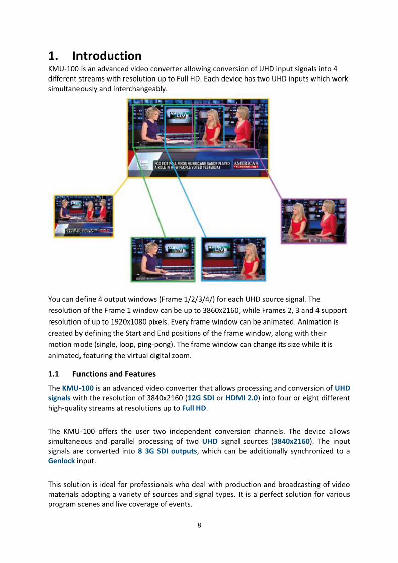
1. Introduction KMU-100 is an advanced video converter allowing conversion of UHD input signals into 4 different streams with resolution up to Full HD. Each device has two UHD inputs which work simultaneously and interchangeably.
You can define 4 output windows (Frame 1/2/3/4/) for each UHD source signal. The
resolution of the Frame 1 window can be up to 3860x2160, while Frames 2, 3 and 4 support
resolution of up to 1920x1080 pixels. Every frame window can be animated. Animation is
created by defining the Start and End positions of the frame window, along with their
motion mode (single, loop, ping-pong). The frame window can change its size while it is
animated, featuring the virtual digital zoom.
1.1 Functions and Features
The KMU-100 is an advanced video converter that allows processing and conversion of UHD signals with the resolution of 3840x2160 (12G SDI or HDMI 2.0) into four or eight different high-quality streams at resolutions up to Full HD.
The KMU-100 offers the user two independent conversion channels. The device allows simultaneous and parallel processing of two UHD signal sources (3840x2160). The input signals are converted into 8 3G SDI outputs, which can be additionally synchronized to a Genlock input.
This solution is ideal for professionals who deal with production and broadcasting of video materials adopting a variety of sources and signal types. It is a perfect solution for various program scenes and live coverage of events.
9
In addition, the KMU-100 converter is really easy to use. The device comes with a complete software package, and the control over all of its functions and parameters is exercised on a LAN connected computer on which the application is installed. The device portability due to its small size, a user-friendly interface, and the DV Link platform will give the user a very pleasant experience with the KMU-100.
1.2 KMU-100 Operations
KMU-100 is able to simultaneously convert signals from two video inputs with resolutions up to UHD (3840x2160) into eight different output video streams. It supports a variety of video formats and allows the connection of SDI and HDMI signal sources including 12G SDI and HDMI 2.0 technologies.
As many as 8 channels of output signals can be generated. Each channel outputs an active area of the input signals defined by the user. To define these areas, a software application is installed on a computer which is connected to the KMU-100 via a LAN interface.
The definition of the area, which will determine the output content, is nothing more than a simple positioning of a frame rectangle in the MultiViewer preview for a given channel. Each of the frame rectangles is marked with a different border color. For one of the frames you can scale the signal from full 4K resolution to Full HD, and there is also up and down scaling (zoom) possible for all other outputs. The output area (position of each frame rectangle) may be a function of a variable, which means the output can be in constant motion. For each frame rectangle, there are simple animations available. The user just needs to select one of the available Motion modes. The start and end positions of the frame rectangle as well as all other related settings are configured on a user friendly interface of the application software installed.
The areas defined by the frame rectangles create 8 SDI outputs (2 x 4 or 1 x 8). Two multiviewer (HDMI) outputs are used for preview and device configuration.
The KMU-100 can be used in different various applications for multiple purposes as this device is capable of generating a variety of effects that will satisfy every professional engaged in production, TV broadcast and event live coverage with the use of audiovisual materials.

10
2. Product Applications The KMU-100 is basically a bridge interfacing 4K technologies with current video systems solutions. This device has a very wide range of applications in virtually every area where the high quality image viewing is required such as sporting events, industrial automation, visual effects used during all kinds of live events or in postproduction.
You can find several applications shown in the diagrams below. These are examples of
possible uses of our device.
2.1 Video Production and Postproduction
The KMU-100 capabilities are perfect for video postproduction compared to other similar products on the market. The video material is recorded with one or two video cameras at 4k resolution. With the KMU-100, you can not only change the composition, but also the shots. The end result will resemble the use of several cameras. With the switcher connected, the transitions between the output images will then be smooth and natural. At the same time, this solution allows the material to be realized by a single camera operator, thus reducing the production cost while keeping the resulting material at a high quality and Full HD resolution. The final effect will be as if it were realized by several operators.

11
2.2 High Quality Security Systems
The KMU-100 is an invaluable tool in creating a top-notch security system. It allows you to receive 3G HD outputs from a single 4K camera. As the KMU-100 processes the signal in real time, you obtain the effect of 8 high-quality mobile video cameras but without their actual movement. In this way, the converter provides new opportunities and possibilities to cut down the costs by reducing the number of video cameras and the cables used, and at the same time increases precision and quality in capturing all important details.
12
3. Connection to the KMU-100 – DV Link A platform that unites all!
The DV Link platform is a very simple and useful software developed for configuration, diagnostics and control of multiple devices (for example four KMU-100 converters) communicating through a common DVIP protocol.
A camera operator or operators can easily change the functions of each of the visible devices or a group by triggering the pre-defined presets, without the need to use the main KMU-100 management application. DV Link application thus allows quick reconfiguration of the equipment for a specific task.
The DV Link platform connects multiple devices to control them on a single application. We invite all the KMU-100 users to download the DV Link application for free. The technical specifications, manual and the download link can be found on the product page.
3.1 Hardware Connection
Prior to the use of the KMU-100, you must first set up the hardware system and configure
the IP settings between the PC and the KMU-100. The subsections below will guide you
through the connection process step by step.
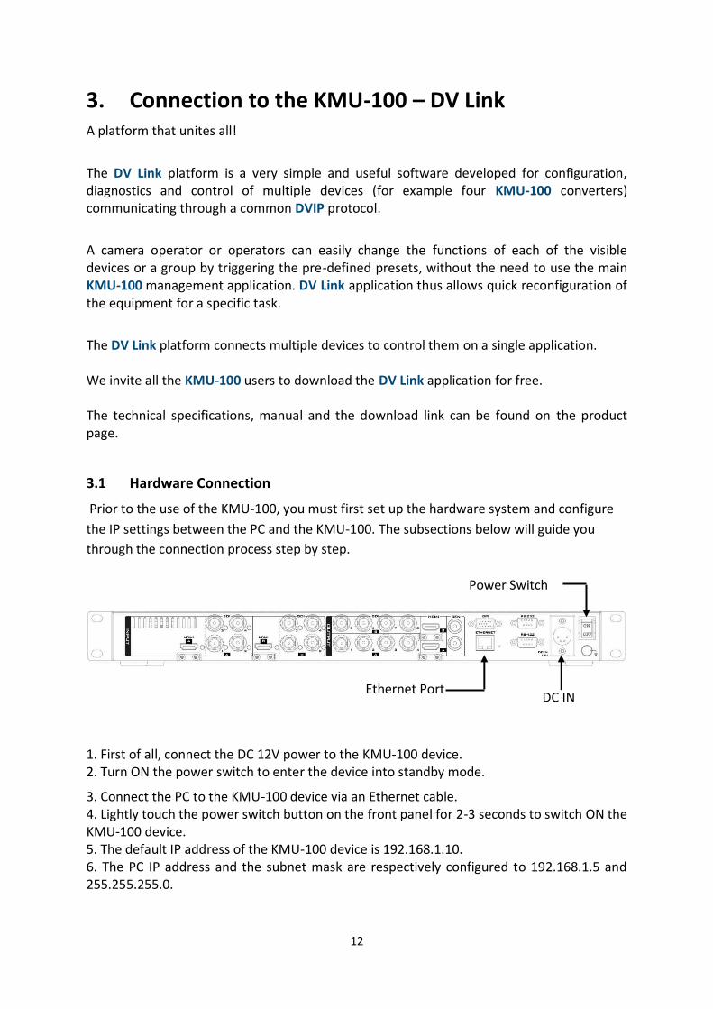
1. First of all, connect the DC 12V power to the KMU-100 device. 2. Turn ON the power switch to enter the device into standby mode.
3. Connect the PC to the KMU-100 device via an Ethernet cable. 4. Lightly touch the power switch button on the front panel for 2-3 seconds to switch ON the KMU-100 device. 5. The default IP address of the KMU-100 device is 192.168.1.10. 6. The PC IP address and the subnet mask are respectively configured to 192.168.1.5 and 255.255.255.0.
DC IN
Power Switch
Ethernet Port

13
7. After the network connection is configured, you can then start the DV Link application to establish the connection between the KMU-100 and the PC.
3.2 Launching DV Link Application
After the DV Link application is downloaded and installed on your computer, simply click the DV Link desktop icon to open the application.
While DV Link application is loading, a screen with a progress bar at the bottom will be displayed as shown in the diagram below.

14
After the DV Link application is loaded, you can see the DV Link start screen as shown in the diagram below.
The DV Link application window can be divided into 4 areas listed as follows:
1. Tool Bar 2. Available Networks 3. Available Devices 4. Single device Control Area (KMU-100)
Tool Bar A Tool Bar is located at the upper left corner of the screen where you will be able to find three main options, File, Options and Help.
15
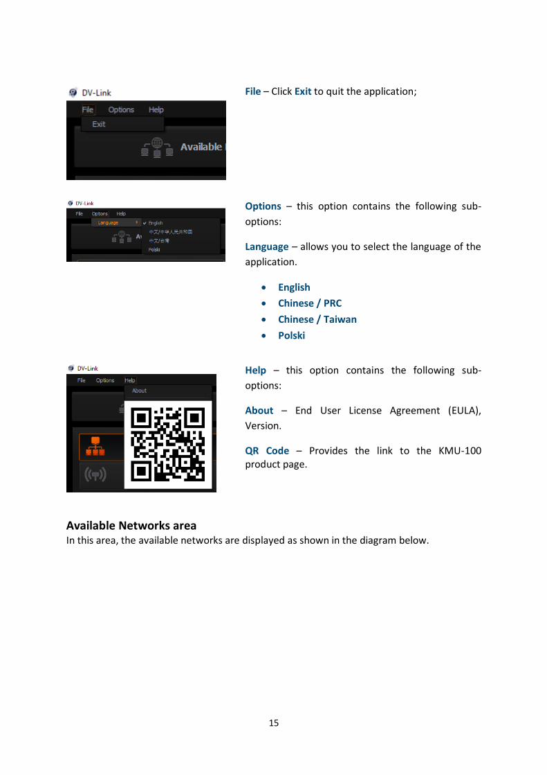
File – Click Exit to quit the application;
Options – this option contains the following sub-
options:
Language – allows you to select the language of the
application.
English
Chinese / PRC
Chinese / Taiwan
Polski
Help – this option contains the following sub-
options:
About – End User License Agreement (EULA),
Version.
QR Code – Provides the link to the KMU-100 product page.
Available Networks area In this area, the available networks are displayed as shown in the diagram below.

16
After moving the cursor over and clicking on a given network icon, the available devices in this network will appear in the Available Devices area.

17
For the selected KMU-100 device, you can load the presets with user settings from one of four Preset slots. You can double click the KMU-100 device icon in the control area (the rightmost KMU-100 column) to open the KMU-100 Control Interface as shown in the diagram below.
The network settings are shown on the bottom of the rightmost column which is shown as above-mentioned diagram. Users can load one of your default settings to the selected KMU-100 device by one of the four Preset keys. Generally speaking, users can find all KMU-100 devices within the same network area by the DV Link software. After the devices are connected, users can load the Preset settings and then they can prepare to control the KMU-100 by opening the KMU-100 application software.

18
4. Control Application The Control Application allows you to configure the device and saves presets in the device internal memory. While the KMU-100 control application is loading, a screen with a progress bar at the bottom will be displayed.
4.1 App Window Descriptions: Connection Tab
The Connection tab allows you to define input signals connected to Channel A and Channel B. It is also possible to use the signal from Input A to process in Channel B, and vice versa, i.e. processing of Input B in Channel A. After clicking the Connection tab, you will see a diagram with visualization of necessary cable connections.

19
The Connection screen window can be divided into 3 areas as shown in the diagram below.
1. Menu area 2. Connection Graphics area 3. Input/Output Signals area
1. Menu area – When the Connection tab turns orange, it indicates that you are working on this particular screen. Pressing the Channel A or Channel B tabs will switch your display from Connection mode to Channel A or Channel B setting (processing) mode. Detailed explanations of the Menu area is in later parts of the manual. 2. Connection Graphics area – The Connection Graphics Area is basically a graphical visualization of the rear panel of the KMU-100 device with all its available inputs and outputs. The active status and the introduced changes to the inputs and outputs are graphically shown on the screen in the form of arrows / orange icons.
In fact, the active inputs / outputs on the rear panel of the KMU-100 device are indicated by glowing LEDs at each input / output port. Color of the diode represents the signal resolution. The LED lights up when a signal is detected at the input.

20
You can see the screenshot of the KMU-100 rear panel as shown in the diagram below. One of the LED locations is indicated by a red arrow.
The LED colors indicating current signal format are displayed on the screen in the top right corner of the graphics area. The diagram below depicts the LEDs description.
When you move the cursor over the input port icon, a preview of the detected format is displayed in a nearby window. In this window, properties such as Format, Resolution, FPS and Mode are displayed as illustrated in the diagram above. The other ports shown in the Connection Graphics Area are listed as follows: Port: 2 x HDMI Video Output (HDMI type A) supporting 1080p60-
For KMU-100: Those two ports allow users to connect to two monitors to show the Multiview screens of the Channel A and Channel B.
For KMU-100+: Those two ports allow user to connect to two monitors to show the Multiview screen (HDMI Output B) and PROGRAM screen (HDMI Output A).
Port: Sync Input (Genlock) allows the specification of the reference signal for synchronization of output channels.
Port: Ethernet RJ45 for control, configuration and firmware updates.

21
Port: RS-422 – For KMU-100: It allows users to connect the RMC-185 KMU Controller to control
the KMU-100. It allows users to control the KMU-100 by the VISCA Protocol. For KMU-100+: It allows users to connect the RMC-185+ KMU Controller to control
the KMU-100+. Moreover, it allows users to control the KMU-100+ by the VISCA Protocol.
Port: RS-232 input is currently unused. DC power supply socket.
3. Input/Output Signals area allows you to configure the KMU-100 device I/O.
Input Signal Configuration You can select an input signal option from the Signal Input A drop-down list as shown below as well as the Signal Input B drop-down list.
There are 4 input signal options in the Signal Input A drop-down list:
4x SDI
1x SDI

22
HDMI
Input Signal B
When you select the 4xSDI option, the four SDI ports in the Input A area will then be highlighted by four orange arrows as illustrated in the diagram below.
After configuring Signal Input A, you can do the same with Signal Input B. There are 4 options in the Signal Input B drop-down list:
4x SDI
1x SDI
HDMI
Input Signal A
When there is no input source for the Input B, users can copy the signal source of the Input A to the Input B. Please select “Input Signal A” option from the Signal Input B drop-down menu.

23
Users can double the number of frame windows on the same image for copying the signal source of the Input A to the Input B. For example, 8 frame windows instead of 4.
Output Signal Configuration There are several output signal format options in the Output Format drop-down list. The available formats are:
SD PAL/NTSC
SD 16:9 PAL/NTSC
720p 50/59.94/60
1080i 50/59.94/60
1080p 25/29.97/30
1080p 50/59.94/60

24
4.2 App Window Descriptions: Channel A and Channel B
Channel A (Channel B is the same as the Channel A)
The Channel A and Channel B tabs are used for defining the way the input signal is divided into 4 different outputs. It is done by placing 4 different frame windows (1, 2, 3 and 4). Content of the area bordered by each frame rectangle will be send to a corresponding output channel.
The Channel A (B) screen window can be divided into 4 areas as illustrated in the diagram below: 1. Menu Area 2. Central Work Area 3. Frame 1, 2, 3 and 4 Setting (Control) Area 4. Multiviewer – Preview on the Monitor
Menu Area
Channel A (B) tab turns orange, indicating that the work is being done on this screen window. Clicking the Channel B tab will switch to the Channel B screen window.
Central Work Area
In this area, the frame windows are defined and sent to the corresponding outputs.
To improve UI clarity, every output is configured in a separate tab, Frames 1/2/3/4. Frame window size and position can be set with mouse clicks (on central work area) or by entering the exact size/position values in the Frame Setting Area on the right of the Channel A (B) screen window.

25
Frame Window Size – This can be configured on the central work area by clicking on any corner or edge of the frame window with the mouse cursor. The window proportions are always retained as the rectangle is in 16:9 aspect ratio. Size of Frame Window 1 is unrestricted as you can configure it up to the input format, even 4K. See the diagram below (current position and size).
Frame Windows 2, 3 and 4 support resolution up to 1080p and the application restricts them from extending further.
A double click on the edited window will switch it to the max available size and the second double click will restore it to its previous size. Aspect ratio is defined by the output resolution and automatically applied to frame window definition.
You can set a graphical background for the gray workspace of the Central Work Area, and the graphical background should help you better position the frame windows.
Frame 1, 2, 3 and 4 Setting (Control) Area Frame Window selection – Click the appropriate Frame 1, 2, 3 or 4 tab on the rightmost side of the work space to start configuring selected Frame Window. The selected Frame is indicated by an orange tab as shown in the diagram below.

26
So far we’ve covered frame windows 1, 2, 3 and 4 defined as fixed (stationary) in their Start positions. However, every frame window can be animated.
To animate the Frame Window, all you need to do is to select the size and position of the Start rectangle and Stop rectangle. The position and the size of the Start and Stop rectangles can be defined using the mouse cursor or by entering the position coordinates in the Frame Setting Area (Current position and size and Destination position and size). If you want to set the final window position exactly in the place where the start window is, you can simply click the From Current button. After the From Current button is clicked, you should be able to see the Start window overlapping the Stop window (in identical positions).

27
Stop rectangle is drawn in dash mode. In the picture below, you can see that the Start rectangle is indicated by a short arrow and the Stop rectangle is indicated by a longer arrow.

28
Motion Mode – You can select the motion mode in the Frame Setting Area. The available options are:
Single – Single movement from Start to Stop.
Loop – Cyclical movement, i.e. Start-Stop, Start-Stop and so on. Ping-Pong – Swing cyclical movement, i.e. Start-Stop,
Stop-Start, Start-Stop and so on (pendulum swing
motion).
Trig. Loop – This can trigger cyclical movement. i.e.
Start-Stop, Start-Stop and so on.
Trig. Ping-Pong –This can trigger Swing cyclical movement, i.e. Start-Stop, Stop-Start, Start-
Stop and so on (pendulum swing motion).
Trig. Double Ping-Pong – This can trigger dual Swing cyclical movement, i.e. Start-Stop,
Stop-Start, Start-Stop and so on.
Note:You will see the animation as virtual movement of the camera shot.
In addition to changing the window position, you can define its size as well, thereby effectively realizing a virtual zoom function. As shown in the diagram below, the Stop window is much smaller size than the Start window.
After selection of the motion mode, you are then allowed to select one of the three speed modes (slow, medium, or fast) as shown in the diagram below.

29
After the size and position of start and stop windows, motion type and speed mode are configured, you can start the animation by clicking Play button.
Note:The motion speed range is from 1-15.
Multiviewer – Preview on the Monitor Three Multiview modes including “Preview”, “Motion” and “Quad View” are shown as following diagram.
Preview – Four rectangles at their respective Start positions are visible on the live input. In the diagram below, frame window 1 covers the entire screen. Press the “Play” button allows the four Frames to move simultaneously.
Motion preview– Press one of the Frame tabs allows users to preview the “Start Position” and “End Position” by the connected external monitor. The start position and end position

30
of the Frame 1 are shown as following diagram. Please press the “Play” button and then users can see that the Frame moves from the start position to the end position.
Quad view – In the Quad View mode, preview of contents of the four outputs is displayed on the monitor as shown in the diagram below.

31
How to Save the Preset Settings and How to Recall the Pre-saved Preset Settings
When the characters, position and motion mode are set, those parameters can be set to one of the four Preset which is located on the bottom of the window. Please press the “Default Positions” button to set those Frames to their original default positions.
Please follow following steps for saving the Preset settings. 1. Please press the “Save Preset” button to open the window for saving preset.
2. Please select the “Preset 1”, “Preset 2”, “Preset 3” or “Preset 4” on the left side of the
pop-up window. After that, please press the “Save” button for saving the current settings into the corresponding Preset.
Please follow following steps for recalling the Preset settings. 1. What you have to do is to press the “Preset 1”, “Preset 2”, “Preset 3” or “Preset 4” button on the main interface of the KMU-100 control software for adopting the corresponding Preset settings.

32
4.3 Tool Bar
There is a Menu bar in the top left corner of your screen. You can find three main options which are File, Options, and Help. The table below shows the sub-options that pop up when you click on the respective main options.
File Exit Quit the application
Options
Language
Select the language English Chinese/PRC Chinese/Taiwan Polski
Configuration
Additional application settings Information about the device SDI 3G output type Firmware Network configuration Triggers Temperatures
Help
About About KMU-100: End User License Agreement (EULA), Device, Version.
A link to the KMU-100 product page.

33
5. How to Operate the KMU-100 5.1 How to Operate the KMU-100 by the Control Software
Please follow following steps for operating the KMU-100 by the KMU-100 control software.
1. Please make sure that your KMU-100 is connected successfully according to 3.1 Hardware
Connection. Moreover, please confirm that the HDMI or SDI input source is connected
successfully.
2. Please open the DV-Link and the KMU-100 control software according to 3.2 Launching
DV Link Application.
3. After the KMU-100 control software is launched, the main interface is shown as following
diagram. Please select the input source interface and the input source format from the
drop-down menus which are surrounded by the red rectangulars.
34
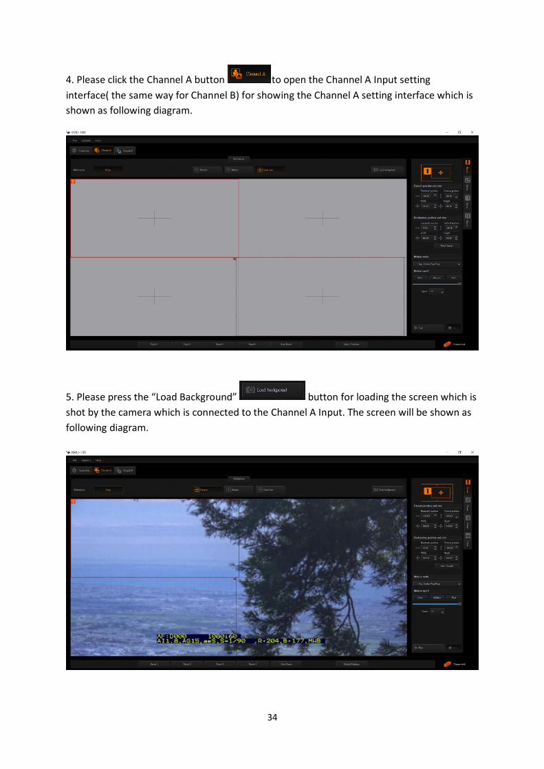
4. Please click the Channel A button to open the Channel A Input setting
interface( the same way for Channel B) for showing the Channel A setting interface which is
shown as following diagram.
5. Please press the “Load Background” button for loading the screen which is
shot by the camera which is connected to the Channel A Input. The screen will be shown as
following diagram.

35
6. If the Preview/Motion/Quad view mode is selected.
Preview
If the “Preview” button is pressed, users can see the following preview screen by the external connected monitor which is connected to the “MULTIVIEW B” HDMI interface which is located on the rear panel of the KMU-100.
If there is an external connected monitor which is connected to the “MULTIVIEW A”HDMI interface which is located on the rear panel of the KMU-100, users can see the No. 5 to No. 8 Preview screens on the external connected monitor. However, if there is one external
connected monitor only, users can press the “Swap” button for showing the No. 5 to No. 8 Preview screens on the same external connected monitor.
960 x 540
960 x 540 960 x 540
960 x 540 960 x 540
960 x 540 960 x 540
5 6
7 8
960 x 540
1 2
3 4
36
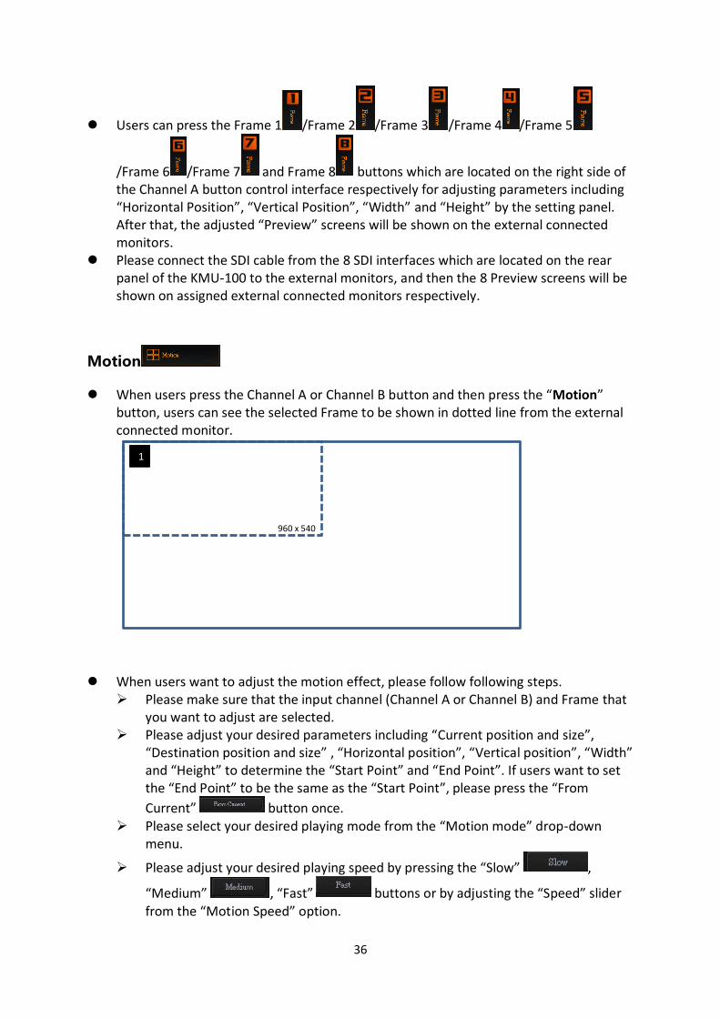
Users can press the Frame 1 /Frame 2 /Frame 3 /Frame 4 /Frame 5
/Frame 6 /Frame 7 and Frame 8 buttons which are located on the right side of the Channel A button control interface respectively for adjusting parameters including “Horizontal Position”, “Vertical Position”, “Width” and “Height” by the setting panel. After that, the adjusted “Preview” screens will be shown on the external connected monitors.
Please connect the SDI cable from the 8 SDI interfaces which are located on the rear panel of the KMU-100 to the external monitors, and then the 8 Preview screens will be shown on assigned external connected monitors respectively.
Motion
When users press the Channel A or Channel B button and then press the “Motion” button, users can see the selected Frame to be shown in dotted line from the external connected monitor.
When users want to adjust the motion effect, please follow following steps. Please make sure that the input channel (Channel A or Channel B) and Frame that
you want to adjust are selected. Please adjust your desired parameters including “Current position and size”,
“Destination position and size” , “Horizontal position”, “Vertical position”, “Width” and “Height” to determine the “Start Point” and “End Point”. If users want to set the “End Point” to be the same as the “Start Point”, please press the “From
Current” button once. Please select your desired playing mode from the “Motion mode” drop-down
menu.
Please adjust your desired playing speed by pressing the “Slow” ,
“Medium” , “Fast” buttons or by adjusting the “Speed” slider from the “Motion Speed” option.
1
960 x 540

37
Finally, please press the “Play” button and then users can see the selected screen to move from the “Start Point” to the “End Point” from the external connected monitor. If users want to stop the playing, please press the “Stop” button.
Quad View
When users press the “Channel A” or “Channel B” button and then press the “Quad
view” button, users can see that the Frame which is shot by the camera to be shown in
Quad View mode from the external connected monitor.
When users want to adjust the motion effect, please follow following steps. Please make sure that the input channel and Frame that users want to adjust are
selected properly. Please adjust your desired parameters including “Current position and size”,
“Destination position and size” , “Horizontal position”, “Vertical position”, “Width”
1
1 960 x 540
960 x 540
The solid rectangular represents the
start point of the current selected
screen.
The dotted rectangular represents the end point for the movement of the current selected screen.
2
4
960 x 540 960 x 540
960 x 540 960 x 540
1
3
960 x 540

38
and “Height” to determine the “Start Point” and “End Point”. If users want to set the “End Point” to be the same as the “Start Point”, please press the “From
Current” button once. Please select your desired playing mode from the “Motion mode” drop-down
menu.
Please adjust your desired playing speed by pressing the “Slow” ,
“Medium” , “Fast” buttons or by adjusting the “Speed” slider from the “Motion Speed” option.
Finally, please press the “Play” button and then users can see the selected screen to move from the “Start Point” to the “End Point” from the external connected monitor. If users want to stop the playing, please press the “Stop” button.
How to Save Current Settings by Preset for Recalling Directly in the Future
The KMU-100 control software allows users to save current settings in Preset for recalling directly in the future.
Please follow following steps for saving and recalling the Preset settings.
How to Save Current Settings in Preset
At first, please make sure that your desired settings including “Horizontal position”, “Vertical position”, “Width” and “Height” are set in advance.
Please press the “Save Preset” button. Please select your desired Preset slot from the Preset 1 to Preset 4 which are located
on the left side.
Please press the “Save” button and then the current settings will be saved as Preset.
How to recall the Pre-saved Preset Settings
Please press the Preset 1 to Preset 4 buttons for recalling the pre-saved Preset.

39
About Default Position Button
Users can press the Default Positions button for setting the “Current position and size”, “Destination position and size”, “Horizontal position”, “Vertical position”, “Width” and “Height” parameters back to the factory default values.
5.2 How to Use the RMC-185 to Control the KMU-100
The KMU-100 can be controlled by not only the KMU-100 control software but also the RMC-185
KMU controller.
Please follow following steps for controlling the KMU-100 by the RMC-185 KMU controller.
5.2.1 How to connect the RMC-185 KMU controller and KMU-100 4K
multi-camera processor
Please pay attention that you have to connect the RMC-185 and KMU-100 system together. Please
follow following steps for connecting the KMU1-100 and the RMC-185. (Take two external
connected video sources as an example).
The KMU-100 is made by installing the KMU-100 V134E7 firmware plus the RMC-185 KMU
controller with the V1.006 firmware.
1. Please connect two external connected video source (e.g. 4K camera or HDMI video source) to the
HDMI INPUT A and HDMI INPUT B interface which are located on the rear panel of the KMU-100.
2. Please use two HDMI cables to connect the two external connected monitors to the MULTIVIEW
OUTPUT B and MULTIVIEW OUTPUT A interfaces which are located on the rear panel of the KMU-
100. The MULTIVIEW OUTPUT B interface is located on the upper side for outputting the Multiview
preview screens of the Frame5, Frame6, Frame 7 and Frame 8. The Multiview OUTPUT A interface is
located on the lower side for outputting the Multiview preview screens for the Frame 1, Frame 2,
Frame 3 and Frame 4.
3. Please use an RJ-45 to RS-422 adapter cable to connect from the KMU REMOTE RJ-45 interface
which is located on the rear panel of the RMC-185 to the RS-422 interface which is located on the
rear panel of the KMU-100.
4. Please use an RJ-45 Ethernet cable to connect from the RJ-45 Ethernet interface which is located
on the rear panel of the KMU-100 to the RJ-45 Ethernet interface of your laptop.
5. Please use 8 SDI cables to connect from the SDI OUTPUT1 to SDI OUTPUT8 interfaces to 8 SDI
Input interfaces of the switcher to be the video input sources of the switcher. Moreover, users can
connect the KMU-100 to 8 external connected monitors to be their video input sources.
6. Until this step, users can prepare to control the KMU-100 by the RMC-185. For the detailed
introduction of the RMC-185 KMU controller, please refer to following paragraphs.

40
6. Introduction of the RMC-185 Controller The RMC-185 is a cost effective physical controller designed specifically for control of the KMU-100 4K Multi-Camera Processor. The RMC-185 interfaces with the KMU-100 via an RS-422 interface. The RMC-185 panel style design allows easy control of the KMU-100 with the hard keys giving the user quick access to main functions of the KMU-100. In addition, you can also use the joystick to move the selected frame view.
6.1 Notices for Device Setup
The RMC-185 is designed to control the KMU-100. Therefore, before pairing the RMC-185
with the KMU-100, the user should first ensure that the two devices are installed of the two
pieces of firmware as listed below:
KMU-100: V134E7
RMC-185: V1.006
After the devices have been successfully upgraded to their corresponding firmware, connect
the power to the RMC-185 through a power cable. After that, the RMC-185 (RJ-45) is
connected to the KMU-100 (DSub) using an RJ-45-to-DSub cable. Finally, turn ON the RMC-
185+ device switch to start manipulating your KMU-100+.
Note: The communication protocol between the two devices is RS-422.

41
6.2 Connections and Controls of the RMC-185
6.2.1 Front Panel-Keyboard
LCD Display
The RMC-185 status or the setup menu options
are displayed on the LCD panel.
Menu Control Dials
The RMC-185 configuration menu can be
entered and browsed using these dials. Push to
select a specific item and rotate to browse the
selected menu option.
Multiviewer Mode Select
P Preview
Press to display current position of the
selected frame.
M Motion
Press to display motion of the selected
frame (playback of the motion from

42
Start position to End position).
Q Quad View
Simultaneous display of all four
frames.
Frame selection buttons (Top row)
Press one button (1-8) to select an active frame.
After selecting an active frame, you can press
the same button to switch between Start and
End positions.
Motion operation buttons (Bottom row)
Press one button to start motion of an active
frame and the second button press pauses
motion. Long pressing the same button for
about 2 seconds will stop motion. Button LED
flashes while the motion is in progress. When
the motion is stopped, the button LED will stop
flashing and turn to constant lit.
PTZ Joystick Control
Note: Before attempting to use the joystick to
PAN, TILT or ZOOM a selected frame, first make
sure the LOCK button is not enabled.
PAN – Move the joystick left or right to pan the
selected frame from left to right or vice versa.
TILT – Move the joystick up or down to tilt the
selected frame up or down.
ZOOM – Twist the joystick clockwise (to the
right) or anti-clockwise (to the left) to have the
selected frame zoom in or out.

43
LOCK Button
When enabled, the joystick will be in the lock
state. To resume its functional status, simply
press the button once to unlock the joystick.
Speed
The speed at which the selected frame moves
can be chosen by pressing one of the three
speed buttons.
STORE
Pressing this button enters the RMC-185 into
STORE MODE. When activated, this allows the
current device setting to be stored in a chosen
Preset Button by pressing the corresponding
Preset Button. Press again to exit STORE MODE.
PRESETS
The preset buttons may be used to store up to
four device settings. Each button corresponds to
one stored device preset. Simply press the
button to recall the saved preset. Once
activated, the button LED will be turned ON.

44
6.2.2 Rear Panel-Connections
Firmware Upgrade
USB type A port for connection to a computer during the firmware
upgrade process.
RJ-45 port to connect the KMU-100
The RJ-45 ports are provided on the RMC-185 rear to connect the KMU-
100. The communication protocol is RS-422, so use an RJ-45-to-DSub
cable to connect the RMC-185 to the RS-422 port located on the KMU-
100 rear panel.
DC In Socket
Connect the supplied 12V 0.5A PSU to this socket. The connection can
be secured by screwing the outer fastening ring of the DC In plug to the
socket.
Power On/Off Switch
Switches the device ON / OFF.

45
6.2.3 RMC-185 Menu Setup
Press the MENU button to enter the MENU. The RMC-
185 status or the setup menu options are displayed on
the LCD panel.
Press the dial to select a particular option and rotate
the dial to browse through the option items.
FN1 Exit
FN2 Input A Source
1 x SDI
4 x SDI
HDMI
Clone
FN3 Input B Source
1 x SDI
4 x SDI
HDMI
Clone
FN4 Output Format
PAL
NTSC
PAL 16:9
NTSC 16:9
720p50
720p59.94
720p60
1080p25
1080p29.97
1080p30
1080i50

46
1080i59.94
1080i60
1080p50
1080p59.94
1080p60
FN5 Genlock Set
Genlock Enable
Disable
Termination Enable
Disable
FN6 Genlock Status
Ref
Present
Loose
Lock
Unlock
Format Detected video format
Up to 1080p60
FN7 SDI 3G Type Type A
Type B
FN8 Multi. Swap ON
OFF
FN9 Multi. SDI ON
OFF
FN10 Trigger Set
Motion No. 1 – 8
Trigger Level Low
High
FN11 KMU-100 Ver. FPGA / HARDWARE / NIOS / ARM

47
FN12 KMU-100 Temp FPGA Temperature
PCB Board Temperature
FN13 Firmware Ver. RMC-185 Firmware Version
FN1. Exits the MENU (EXIT) Exits the setup menu mode.
FN2. Input A Source Assignment (Input A Source) In this option, you may select a source for input A image processing. The available interfaces are:
1xSDI – SDI video interface up to 12G (SD is not supported)
4xSDI – quad SDI video
HDMI – HDMI 2.0
Clone – Input B as a source
FN3. Input B Source Assignment (Input B Source) In this option, you may select a source for input B image processing. The available interfaces are:
1xSDI – SDI video interface up to 12G (SD is not supported)
4xSDI – quad SDI video
HDMI – HDMI 2.0
Clone – Input A as a source
FN4. Output Format Selection (Output Format) There are many video output formats available for selection. The available video output formats are listed as follows:
PAL
NTSC
PAL 16:9
NTSC 16:9
720p50
720p59.94
720p60
1080p25
1080p29.97
1080p30
1080i50
1080i59.94
1080i60
1080p50
1080p59.94
1080p60

48
FN5. Genlock Setting (Genlock Set) This option enables/disables the genlock functionality and turns ON/OFF internal 75 Ohm termination.
FN6. Genlock Status Display (Genlock Status) Display current genlock status by returning values detected from sync signal.
FN7. Selection of SDI 3G Type (SDI 3G Type) Enabling of 3G-SDI signal type on output ports (available modes are Type A and Type B).
FN8. HDMI Multiviewer Swap (Multi. Swap) If Multi. Swap is set to ON, the multiviewer contents of the KMU-100 HDMI outputs will be swapped.
FN9. SDI 4 Multiviewer (Multi. SDI) If Multi.SDI is set to ON, the 4th SDI output of every output channel on the KMU-100 works as a multiviewer output.
FN10. External Motion Trigger Setting (Trigger Set) In this option, you will be able to configure the external motion trigger method. Motion 1-8 can be controlled by an external device using the level trigger method. You can either set the trigger method to low level trigger or high level trigger.
FN11. KMU-100 Firmware Version Display (KMU-100 Ver.) Upon entering the KMU-100 Ver. Option, the KMU-100 firmware version will be displayed.
FN12. Display of KMU-100 FPGA and PCB Board Temperatures (KMU-100 Temp) In the KMU-100 Temp option, you will be able to check measured temperatures of the KMU-100 FPGA and PCB boards.
FN13. RMC-185 Firmware Version Display (Firmware Ver.) Upon entering the Firmware Ver. option, the RMC-185 firmware version will be displayed.

49
7. How to Store Different Device Settings of the
RMC-185
The RMC-185 allows you to store up to four device settings. Follow the procedure below to
store the current device setting to one of the preset buttons.
To store a device setting:
1. Adjust the frame positions using the joystick.
2. Push the STORE button and it will turn red.
3. Press a preset button to save the current device setting.
4. The selected preset button will remain ON for 2-3 seconds and the button LED will be turned OFF after the device setting is successfully saved.

50
8. How to Set the Frame Motion Configuration of the
KMU-100 by the RMC-185
1. At first, please press the “M” button which is located in the middle of the MULTIVIW 1 or MULTIVIEW 2 button row.
2. Press one of the STOP row buttons (buttons 1’ to 8’) to select a frame to adjust its motion setting.
3. Use the joystick to zoom the frame and adjust its start position (fine border frame).
4. Press the button (one of the STOP row buttons 1’ to 8’) selected at Step 2 again.

51
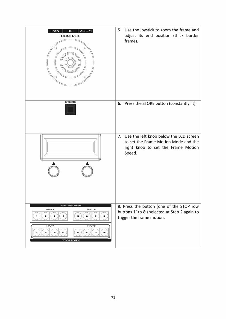
5. Use the joystick to zoom the frame and adjust its end position (thick border frame).
6. Press the STORE button (constantly lit).
7. Use the left knob below the LCD screen to set the Frame Motion Mode and the right knob to set the Frame Motion Speed.
8. Press the button (one of the STOP row buttons 1’ to 8’) selected at Step 2 again to trigger the frame motion.

52
9. How to Operate the KMU-100+ (Can be controlled by the RMC-185+ KMU Controller Only) At first, please note that the KMU-100+ can not be controlled by the KMU-100 control
software, it can be controlled by the RMC-185+ KMU controller only.
Please follow following steps for controlling the KMU-100+ by the RMC-185+ KMU controller.
9.1 How to Connect the RMC-185+ KMU Controller and the KMU-100+ 2-Channel 4K
Multicamera Processor
Please pay attention that before controlling the KMU-100+ by the RMC-185+ KMU
controller, users need to connect the RMC-185+ to the KMU-100+ system. Please follow
following steps for connecting the KMU-100+ and the RMC-185+. (Take two external
connected image sources as an example in following paragraphs)
The KMU-100+ is made by upgrading the firmware of the original KMU-100 to v.1.0.14745
plus the firmware upgrading for the original RMC-185+ KMU controller to v.1.012.
1. Please connect two external connected video sources (such as 4K camera or HDMI video
source) to the HDMI INPUT A and HDMI INPUT B interfaces which are located on the rear
panel of the KMU-100+。
2. Please use two HDMI cable to connect the two external monitors to the MULTIVIEW OUT
B and the MULTIVIEW OUT A interface. The MULTIVIEW OUT B interface is located on the
upper side for the MULTIVIEW PREVIEW screen output. The MULTIVIEW OUTPUT A
interface is located on the lower side for the PROGRAM screen output.
3. Please use an RJ-45 to RS-422 adapter cable to connect from the KMU REMOTE RJ-45
interface which is located on the rear panel of the RMC-185+ to the RS-422 interface which
is located on the rear panel of the KMU-100+.
4. Please use an RJ-45 Ethernet cable to connect the KMU-100+. Please connect from the RJ-
45 Ethernet interface which is located on the rear panel of the KMU-100+ to the RJ-45
Ethernet interface of your laptop.
5. Please connect 8 SDI cables from the SDI OUTPUT 1 to SDI OUTPUT 8 interfaces which are
located on the rear panel of the KMU-100+ to the 8 SDI input interfaces of the switcher to
be the video input sources of the switcher. Moreover, users can connect the KMU-100+ to 8
external connected monitors to be the video input sources of those monitors.
6. Until this step, users can prepare to control the KMU-100+ by the RMC-185. For detailed
introduction of the RMC-185+ KMU controller, please refer to following paragraphs.

53
10. Introduction and Operation of the RMC-185+ KMU Controller 10.1 Introduction of the RMC-185+ KMU Controller
The RMC-185+ is a cost effective physical controller designed specifically for control of the
KMU-100+ 4K Multi-Camera Processor. The RMC-185+ interfaces with the KMU-100+ via an
RS-422 interface.
The RMC-185+ panel style design allows easy control of the KMU-100+ with the hard keys
giving the user quick access to main functions of the KMU-100+. In addition, you can also
use the joystick to move the selected frame view.
10.2 RMC-185+ Features
Remote control of up to eight selected frame views.
Pan, Tilt and Zoom with speed control by joystick.
Storing multiple presets for frame view settings.
Full remote control of the KMU-100+ via RS-422 connection.
An LCD display showing setup menu options.
Two Multiviewer modes (Switcher and KMU modes)
Compact design for easy installation
10.3 Notices for Device Setup
The RMC-185+ is designed to control the KMU-100+. Therefore, before pairing the RMC-
185+ with the KMU-100+, the user should first ensure that the two devices are installed of
the two pieces of firmware as listed below:
KMU-100+: V1.0.14745
RMC-185+: V1.012
After the devices have been successfully upgraded to their corresponding firmware, connect
the power to the RMC-185+ through a power cable. After that, the RMC-185+ (RJ-45) is
connected to the KMU-100+ (DSub) using an RJ-45-to-DSub cable. Finally, turn ON the RMC-
185+ device switch to start manipulating your KMU-100+. See the system diagram below for
the overall system setup.
Note: The communication protocol between the two devices is RS-422.

54
11. System Diagram of the RMC-185+ and KMU-100+ Connection
55
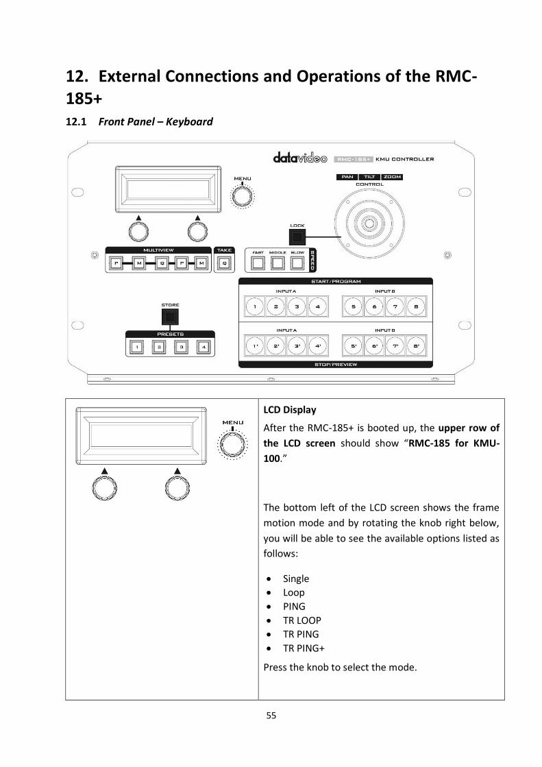
12. External Connections and Operations of the RMC-185+ 12.1 Front Panel – Keyboard
LCD Display
After the RMC-185+ is booted up, the upper row of
the LCD screen should show “RMC-185 for KMU-
100.”
The bottom left of the LCD screen shows the frame
motion mode and by rotating the knob right below,
you will be able to see the available options listed as
follows:
Single
Loop
PING
TR LOOP
TR PING
TR PING+
Press the knob to select the mode.

56
The bottom right of the LCD screen shows the frame
motion speed and by rotating the knob right below,
you will be able to change the speed from 1 to 15.
Press the knob the set the speed.
Menu Control Knob
Push the Menu Control Knob to enter and browse
the RMC-185+ configuration menu. Once in the
menu, you can either push the menu knob to select
a specific item or rotate to browse the selected
menu option (or adjust the parameter value of the
selected option).
Certain options of the menu will require the user to
use the two knobs below the LCD screen to adjust
the parameter values and these values can be set by
pushing the corresponding knobs.
PTZ Joystick Control
Note: Before attempting to use the joystick to PAN,
TILT or ZOOM a selected frame, first make sure the
LOCK button is not enabled.
PAN – Move the joystick left or right to pan the
selected frame from left to right or vice versa.
TILT – Move the joystick up or down to tilt the
selected frame up or down.
ZOOM – Twist the joystick clockwise (to the right) or
anti-clockwise (to the left) to have the selected
frame zoom in or out.
LOCK Button
When enabled, the joystick will be in the lock state.
To resume its functional status, simply press the
button once to unlock the joystick.

57
Multiviewer Mode Select
The Multiviewer buttons allow you to switch between different display modes.
P/M The second rightmost P button opens the multiviewer in KMU Mode, thus displaying current position of the selected frame.
The rightmost M button enables the
Frame Motion function (playback of the
motion from Start position to End
position) of the selected frame in KMU
Mode.
Q The middle Q button opens the
multiviewer in Switcher Mode as shown in
the diagram below.

58
M The second leftmost M button opens the
multiviewer in Switcher Mode as shown in
the diagram below.
P The leftmost P button opens the
multiviewer in Switcher Mode as shown in
the diagram below.
Take
Press this Q button will take the preview image to
air.
59
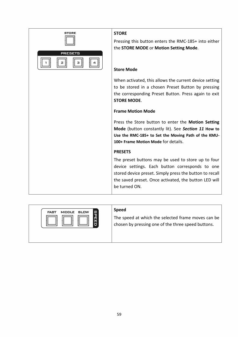
STORE
Pressing this button enters the RMC-185+ into either
the STORE MODE or Motion Setting Mode.
Store Mode
When activated, this allows the current device setting
to be stored in a chosen Preset Button by pressing
the corresponding Preset Button. Press again to exit
STORE MODE.
Frame Motion Mode
Press the Store button to enter the Motion Setting
Mode (button constantly lit). See Section 11 How to
Use the RMC-185+ to Set the Moving Path of the KMU-
100+ Frame Motion Mode for details.
PRESETS
The preset buttons may be used to store up to four
device settings. Each button corresponds to one
stored device preset. Simply press the button to recall
the saved preset. Once activated, the button LED will
be turned ON.
Speed
The speed at which the selected frame moves can be
chosen by pressing one of the three speed buttons.

60
Frame selection buttons (Top row)
Press one button (1-8) to select an active frame. After
selecting an active frame, you can press the same
button to switch between Start and End positions.
Motion operation buttons (Bottom row)
Press one button to start motion of an active frame
and the second button press pauses motion. Long
pressing the same button for about 2 seconds will
stop motion. Button LED flashes while the motion is
in progress. When the motion is stopped, the button
LED will stop flashing and turn to constant lit.
Note: See Section 15 for Frame Motion
Configuration.

61
12.2 Rear Panel - Connections
Firmware Upgrade
USB type A port for connection to a computer during the firmware
upgrade process.
RJ-45 port to connect the KMU-100+
The RJ-45 ports are provided on the RMC-185+ rear to connect the KMU-
100+. The communication protocol is RS-422, so use an RJ-45-to-DSub
cable to connect the RMC-185+ to the RS-422 port located on the KMU-
100+ rear panel.
DC In Socket
Connect the supplied 12V 0.5A PSU to this socket. The connection can be
secured by screwing the outer fastening ring of the DC In plug to the
socket.

62
Power On/Off Switch
Switches the device ON / OFF.

63
13. RMC-185+Menu Setup
Press the MENU button to enter the MENU. The RMC-
185+ status or the setup menu options are displayed
on the LCD panel.
Press the dial to select a particular option and rotate
the dial to browse through the option items.
FN1 Exit
FN2 Input A Source
1 x SDI
4 x SDI
HDMI
Clone
FN3 Input B Source
1 x SDI
4 x SDI
HDMI
Clone
FN4 Output Format
PAL
NTSC
PAL 16:9
NTSC 16:9
720p 50
720p 59
720p 60
1080i 50
1080i 59
1080i 60

64
1080p 25
1080p 29
1080p 30
1080p 50
1080p 59
1080p 60
FN5 Audio Output Mix
Follow
FN6 Genlock Set
Genlock Enable
Disable
Termination Enable
Disable
FN7 Genlock Status
Ref
Present
Loose
Lock
Unlock
Format Detected video format
Up to 1080p60
FN8 SDI 3G Type Type A
Type B
FN9 Output Assign 1~8, PVW, PGM
1~8, PVW, PGM
FN10 Limit
720p
1080p
None

65
FN11 Trigger Set
Motion No. 1 – 8
Trigger Level Rising edge
Falling edge
FN12 KMU-100+ Ver. FPGA / HARDWARE / NIOS / ARM
FN13 KMU-100+ Temp FPGA Temperature
PCB Board Temperature
FN14 Firmware Ver. RMC-185+ Firmware Version

66
FN1. Exits the MENU (EXIT) Exits the setup menu mode.
FN2. Input A Source Assignment (Input A Source) In this option, you may select a source for input A image processing. The available interfaces are:
1xSDI – SDI video interface up to 12G (SD is not supported)
4xSDI – quad SDI video
HDMI – HDMI 2.0
Clone – Input B as a source
FN3. Input B Source Assignment (Input B Source) In this option, you may select a source for input B image processing. The available interfaces are:
1xSDI – SDI video interface up to 12G (SD is not supported)
4xSDI – quad SDI video
HDMI – HDMI 2.0
Clone – Input A as a source
FN4. Output Format Selection (Output Format) There are many video output formats available for selection. The available video output formats are listed as follows:
PAL
NTSC
PAL 16:9
NTSC 16:9
720p 50
720p 59
720p 60
1080i 50
1080i 59
1080i 60
1080p 25
1080p 29
1080p 30
1080p 50
1080p 59
1080p 60

67
FN5. Audio Output If Audio Follow is selected, audio settings are described below: SDI Ch 1 / 2 / 3 / 4: Input A audio SDI Ch 5 / 6 / 7 / 8: Input B audio
Audio Mix: Input A audio and Input B audio will be simultaneously on the HDMI OUT2 (PGM). Note: The Audio Mix option will be available only if Mix HDMI OUT2 (PGM) or SDI OUT is set to PVW / PGM.
FN6. Genlock Setting (Genlock Set) This option enables/disables the genlock functionality and turns ON/OFF internal 75 Ohm termination.
FN7. Genlock Status Display (Genlock Status) Display current genlock status by returning values detected from sync signal.
FN8. Selection of SDI 3G Type (SDI 3G Type) Enabling of 3G-SDI signal type on output ports (available modes are Type A and Type B).
FN9. Output Assign This option sets SDI Output 1-8 to either one of 1-8, PVW and PGM. EX: All SDI Output 1-8 can be set to PGM view.
FN10. Limit This option limits the minimum size of the motion window. Note: LIMIT is available for 4K input only.
FN11. External Motion Trigger Setting (Trigger Set) In this option, you will be able to configure the external motion trigger method. Motion 1-8 can be controlled by an external device using the level trigger method. You can either set the trigger method to low level trigger or high level trigger.
FN12. KMU-100+ Firmware Version Display (KMU-100+ Ver.) Upon entering the KMU-100+ Ver. Option, the KMU-100+ firmware version will be displayed.

68
FN13. Display of KMU-100+ FPGA and PCB Board Temperatures (KMU-100+ Temp) In the KMU-100+ Temp option, you will be able to check measured temperatures of the KMU-100+ FPGA and PCB boards.
FN14. RMC-185+ Firmware Version Display (Firmware Ver.) Upon entering the Firmware Ver. option, the RMC-185+ firmware version will be displayed.

69
14. How to Use the RMC-185+ to Store the Preset Settings of the KMU-100
The RMC-185+ allows you to store up to four device settings. Follow the procedure below to store the current device setting to one of the preset buttons.
To store a device setting:
1. Adjust the frame positions using the joystick.
2. Push the STORE button and it will turn red.
3. Press a preset button to save the current device setting.
4. The selected preset button will remain ON for 2-3 seconds and the button LED will be turned OFF after the device setting is successfully saved.

70
15. How to Set the Frame Motion Configuration of the KMU-100+ by the RMC-185+
1. First enable the rightmost M button of the MULTIVIEW button row.
2. Press one of the STOP row buttons (buttons 1’ to 8’) to select a frame to adjust its motion setting.
3. Use the joystick to zoom the frame and adjust its start position (fine border frame).
4. Press the button (one of the STOP row buttons 1’ to 8’) selected at Step 2 again.
71
5. Use the joystick to zoom the frame and adjust its end position (thick border frame).
6. Press the STORE button (constantly lit).
7. Use the left knob below the LCD screen to set the Frame Motion Mode and the right knob to set the Frame Motion Speed.
8. Press the button (one of the STOP row buttons 1’ to 8’) selected at Step 2 again to trigger the frame motion.

72
16. How to Upgrade the Firmware of the KMU-100/KMU-100+ From time to time, Datavideo may release new firmware to either add new features or to fix
reported bugs in the current KMU-100/KMU-100+ firmware. Customers can update the
firmware themselves if they wish or they can contact their local dealer or reseller for
assistance
This section describes the firmware update process and it should take approximately few minutes to complete. Once started, the update process should not be interrupted in any way as this could result in a non-responsive unit. Please follow following steps for upgrading the KMU-100/KMU-100+ firmware. 1. Please download the latest KMU-100 firmware from the Datavideo official website www.datavideo.com . 2. Please set your laptop to be within the same network area as the KMU-100/KMU-100+. 3. Please launch KMU-100’s DV-Link control software.
4. Please press the “Ethernet (乙太網路)” button from the “Available Network”.
5. Please press the connect button from “Available Devices”.
6. Please press the KMU-100 icon to launch the main interface of the KMU-100 control
software.

73
7. Please press the “Configuration” option from the “Options” drop-down menu.
8. Please press the “Change” button which is located next to the “Firmware” from the pop-up
window.
9. Please select the downloaded latest version firmware and then please press the “Open” button.

74
10. The “New firmware version” and “Current firmware version” will be shown and then please press the “Update” button for starting the firmware upgrading procedure.
11. Please wait until the updating progress bar to reach 100% and then the firmware upgrading procedure is completed.

75
17. How to Upgrade the Firmware of the RMC-185 & RMC-185+ From time to time, Datavideo may release new firmware to either add new features or to fix
reported bugs in the current RMC-185 & RMC-185+ firmware. Customers can update the
firmware themselves if they wish or they can contact their local dealer or reseller for
assistance should they prefer this method.
This section describes the firmware update process and it should take approximately few
minutes to complete. Once started, the update process should not be interrupted in any
way as this could result in a non-responsive unit.
Requirement:
Latest firmware update files of RMC-185 or RMC-185+ (bootloader and application firmware)
A USB A to USB A cable not longer than 2 meters
A Windows PC with USB 2.0 ports or above
1. Power off the RMC-185 or RMC-185+ and use a USB cable (USB A to USB A) to connect
the USB firmware upgrade port on theRMC-185 or RMC-185+ rear panel to a USB port on the PC.
2. Press and hold the four buttons indicated with at the same time.

76
3. With an assistant’s help, one person switches on the RMC-185 or RMC-185+ device
while another person presses and holds the buttons indicated with .
4. The user may release the buttons once the RMC-185 or RMC-185+ LCD panel displays the following information.
5. The RMC-185 or RMC-185+ device (RMC-185+_U38) will appear as a removable storage device on the PC as shown below.

77
6. Double click the RMC-185_U38 removable storage device and delete the “bootcode.bin”
file. 7. Copy and paste the latest bootloader firmware file (bootcode.bin) into the RMC-
185_U38 removable storage device. 8. Please reboot the RMC-185 or RMC-185+ and then the firmware update procedure is
finished.
9. Users can start to use the RMC-185 or RMC-185+ to control the KMU-100 or KMU-100+.

78
18. Direct Connection of the RMC-185+ KMU Controller and KMU-100+ The RMC-185 KMU Controller is designed to control the KMU-100 via the RS-422 interface using the VISCA Command Protocol.
The RMC-185 panel style design allows easy control of the KMU-100 with the hard keys giving the user quick access to main functions of the KMU-100.
18.1 Direct Connection to KMU-100
To use the RMC-185 KMU Controller to directly control the KMU-100 4K Multi-Camera
Processor, connect the RS-422 port (9 PIN D-Sub) on the KMU-100’s rear panel to the RJ-45
port of the RMC-185 using any RJ-45 cable. The RJ-45 to 9 PIN D-Sub cable wiring scheme is
shown below.
P1 (RJ45) P2 (DB9M)
Green/White 1 ------------------ 1/6/4/9/5
Green 2 ------------------ X
Orange/White 3 ------------------ 8
Blue 4 ------------------ 2
Blue/White 5 ------------------ 7
Orange 6 ------------------ 3
Brown/White 7 ------------------ X
Brown 8 ------------------ X

79
19. KMU-100+’s Test Fixture Circuit Diagram There are three modes including Loop, Ping-Pong and Double Ping-Pong in KMU-100’s
Motion Mode. Those three modes can be triggered by connecting to the GPI interface which
is located on the rear panel of the KMU-100+. Please see the test fixture circuit diagram for
the GPI which is shown as following diagram.
GPI3
SW1
B3S-1000P
14
23
SW1
B3S-1000P
1 4
2 3
SW1
B3S-1000P
14
23
GPI4
GPI7
D2RLED
LED0603
AC
GPI5GPI1
SW1
B3S-1000P
1 4
2 3
SW1
B3S-1000P
14
23
GPI2
P3
DB15_M
11
9
15
8
14
7
13
6
12
10
3
5
4
1
2
SW1
B3S-1000P
1 4
2 3
GPI8
SW1
B3S-1000P
14
23
GPO2
SW1
B3S-1000P
1 4
2 3
D1
GLEDLED0603
AC
GPI6
GPO1

80
20. Frequently-Asked Questions This section describes problems that you may encounter while using the KMU-100. If you
have any questions, please refer to related sections and follow all suggested solutions. If
problem still exists, please contact your distributor or the service center.
For KMU-100 & KMU-100+
No. Problems Solutions
1 The DV LINK APP fails to connect.
Sometimes the DV LINK APP will be disconnected.
2 The PC fails to communicate with the KMU-100
You might be using non-compliant cables which will cause signal failure after connected to the KMU-100.
For RMC-185 & RMC-185+
No. Problems Solutions
1. What is the RJ-45 port used
for?
It is used for connecting the RMC-185 or RMC-
185+ to the KMU-100+. Please use an RJ-45-to-
DSub cable. The DSub end should be a male
connector.

81
21. Dimensions
KMU-100 & KMU-100+

82
RMC-185 & RMC-185+
Unit: mm

83
22. Specifications
KMU-100 & KMU-100+
Connections
SDI Video Input 2 sets of SDI Input: each set of 4x SDI 1 x 3Gb/s or 12Gb/s SD/HD/4K. Supports single link 4:2:2 3 x 3Gb/s SD/HD/4K. Supports single link, dual link, and quad link
4:2:2
2 x (1) - 10 bit HD, 3G levels A and B, 12G UHD switchable 6 x (2,3,4) - 10 bit HD, 3G levels A and B switchable; Usable as Quad SDI; 4x3G SDI input for UHD
HDMI Video Input 2 x HDMI Input: Each of HDMI support for Ultra HD 4K 60p in 4:2:0/4:2:2
SDI Video Output 2 sets of SDI output: each set of 4x SDI 1 x 3Gb/s or 12Gb/s SD/HD/4K. Supports single link 4:2:2 3 x 3Gb/s SD/HD/4K. Supports single link, dual link, and quad link
4:2:2
8 x – 10 bit SD, HD, 3G levels A and B switchable
HDMI Multiviewer Video Output
2x HDMI type A connector with support for 1080p50/59.94/60
SDI Audio Input 16 channels in HD, 3G HD, and UHD
SDI Audio Output 16 channels in HD, 3G HD, and UHD
Multi Rate Support SDI connections are switchable between standard definition, high definition and UltraHD
Sync Input (Genlock) Blackburst or TriSync Computer Interface The Ethernet RJ45 port is used for device control, setting and
update The RS-232 x 1 input communication port is used for device setting.
Software
Software Control A dedicated software control utility application for changing settings via Windows 7, Windows 8, and Windows 10 is included free of charge.
Power Requirement Power Supply External connected 12V / 5A Power Supply
Environmental Specifications Operating Temperature
5° - 50 ° C (41° to 122° F)

84
Storage Temperature -20° - 45°C (-4° to 113°F)
Relative Humidity 0% - 90% non-condensing
Processing-Two Independent Channels Outputs Definition Each channel has a definition of four rectangles indicating the way
the input signal is divided into 4 different outputs. The content bordered by each frame window will be sent to a corresponding output.
Windows Animation Animation is possible for every frame window. User selects the size and position of Start and Stop rectangles. Motion modes available: Single – Single movement from Start to Stop. Ping-Pong – Swing cyclical movement, i.e. Start-Stop, Stop-Start, Start-Stop and so on (pendulum swing motion). Loop – Cyclical movement, i.e. Start-Stop, Start-Stop and so on.
Multiview Output Preview of the outputs: Preview – Four rectangles at their respective Start positions are visible on the live input. Motion preview – The Start, Current and Stop rectangles of the selected Frame tab are visible on the live input. Quad view – Preview of the content of four outputs.
Standards SD Format Support SD output but not support SD
1.5 Gb/s HD Format 720p50, 720p59.94 1080p25 1080p29.97 1080i50 1080i59.94
3 Gb/s HD Format 1080p50, 1080p59.94 and 1080p60 levels A and B
Ultra HD Format 2160p25, 2160p29.97, 2160p50, 2160p59.94
SDI Compliance SMPTE 259M, SMPTE 292M, SMPTE 296M, SMPTE 372M, SMPTE 425M, SMPTE2082-1
Audio Sampling Sample Rate: 48kHz and 24-bit HD, 20-bit SD
Video Sampling 4:2:2
Color Precision 10-bit
Color Space REC 601, REC 709

85
RMC-185 & RMC-185+
RMC-185+ KMU+ Controller
Firmware Update USB
Power DC 12 伏 0.5A
Dimensions (Width x Height x Depth) 310 x 129.98 x 170 (mm)
Net Weight 1.5Kg
Gross Weight 2.0Kg
Operating Temperature 0°C - 50°C (32°F - 122°F)
Humidity 10% - 80%

86
Note

87
Note

Jul-31.2020
Version E1
Datavideo Technologies Co., Ltd. All rights reserved 2020
https://www.datavideo.com/product/KMU-100