kks handbook edition 07
DESCRIPTION
FreeTRANSCRIPT

PRINTED DOCUMENTS NOT VALID
LANDSNET KKS HANDBOOK
December 2008
Edition: 07 Author: VAO/KS
Confirmed: NL
Printed 04.12.08
LANDSNET
KKS HANDBOOK

PRINTED DOCUMENTS NOT VALID
LANDSNET KKS HANDBOOK
CONTENT
December 2008
Edition: 07 Author: VAO/KS
Confirmed: NL Content
VERKFRÆÐISTOFANAFL OG ORKA
Printed 04.12.08 Page C.1
0. PREFACE 2
0.1 GENERAL KKS RULES 3
0.2 RULES ON PROCESS-RELATED IDENTIFICATION 3
0.3 RULES ON POINT OF INSTALLATION IDENTIFICATION 4
0.4 RULES ON LOCATION IDENTIFICATION 4
1. KKS 2
1.1 SCOPE OF KKS 2 1.1.1 TYPE OF CODE 2 1.1.2 BREAK DOWN LEVELS, PREFIX AND BREAKDOWN SYMBOLS 4 1.1.3 KKS CODE 5
1.2 CONTENTS OF DATA CHARACTERS 5 1.2.1 BREAK DOWN LEVEL ÷1 5 1.2.2 BREAK DOWN LEVEL 0 8 1.2.3 BREAK DOWN LEVEL 1 9 1.2.4 BREAK DOWN LEVEL 2 11 1.2.5 BREAK DOWN LEVEL 3 12
2. NUMBERING 2
2.1 FN NUMBERING 4
2.2 AN NUMBERING 5 2.2.1 NUMBERING OF PIPING SYSTEM 5 2.2.2 NUMBERING OF VALVES 6 2.2.3 AN NUMBERING OF VALVES IN COOLING SYSTEMS 9 2.2.4 EQUIPMENT NUMBERING 10 2.2.5 NUMBERING OF MEASUREMENT POINTS 11

PRINTED DOCUMENTS NOT VALID
LANDSNET KKS HANDBOOK
CONTENT
December 2008
Edition: 07 Author: VAO/KS
Confirmed: NL Content
VERKFRÆÐISTOFANAFL OG ORKA
Printed 04.12.08 Page C.2
3. IDENTIFICATION IN MECHANICAL ENGINEERING 2
3.1 WATER IMPOUNDING WORKS 2 3.1.1 CODING OF WATER IMPOUNDING WORKS 2 3.1.2 CODING OF GATE HYDRAULIC 4 3.1.3 CODING OF GATE HEATING SYSTEM 5
3.2 CODING OF TURBINES 6 3.2.1 FRANCIS TURBINE 6 3.2.2 KAPLAN TURBINE 7 3.2.3 PELTON TURBINE 9 3.2.4 CODING OF STEAM TURBINES 10 3.2.5 GOVERNOR OF A WATER TURBINE 12
3.3 CODING OF GENERATORS 13
3.4 CODING OF AIR-CONDITION SYSTEMS 14
3.5 CODING OF GEOTHERMAL POWER PLANTS 14
4. IDENTIFICATION IN ELECTRICAL, CONTROL AND INSTRUMENTATION ENGINEERING 2
4.1 CODING OF POWER SYSTEMS 2 4.1.1 CODING OF LINE BAYS 3
4.2 CODING OF BUSBARS 8
4.3 CODING OF CIRCUIT BREAKERS, DISCONNECTORS AND EARTHING-SWITCHES 10 4.3.1 EXAMPLES OF CODING OF CIRCUIT BREAKERS, DISCONNECTORS AND EARTHING
SWITHCES 11 4.3.2 SPECIAL CASES OF BREAKER CODING 18
4.4 CODING OF MAIN- AND DISTRIBUTION TRANSFORMERS INCLUDING EQUIPMENT CONNECTED TO TRANSFORMER 20
4.5 MEASURING CIRCUITS 22 4.5.1 CODING OF CURRENT- AND VOLTAGE CIRCUITS 22
4.6 KKS CODING EXAMPLES 26
4.7 CODING OF HIGH VOLTAGE MASTS 31
4.8 CODING FROM GENERATOR TO GENERATOR TRANSFORMER 32 4.8.1 CODING FROM NEUTRAL POINT OF GENERATOR TO GENERATOR TRANSFORMER 32

PRINTED DOCUMENTS NOT VALID
LANDSNET KKS HANDBOOK
CONTENT
December 2008
Edition: 07 Author: VAO/KS
Confirmed: NL Content
VERKFRÆÐISTOFANAFL OG ORKA
Printed 04.12.08 Page C.3
4.9 POWER TRANSMISSION AND AUXILIARY POWER SUPPLY IN POWER PLANTS 34 4.9.1 FURTHER DEFINITION OF DISTRIBUTION IN POWER PLANTS 34
4.10 EQUIPMENT AND POWER CIRCUIT CODING 39
4.11 DEFINITION BY LANDSNET ON FREE ALPHABETICAL CHARACTERS 40 4.11.1 DIRECT CURRENT SYSTEM 40 4.11.2 CABLES, CONDUCTORS, INTERCONNECTING BOXES, BUSBARS AND HV FEED
THROUGH 41
4.12 CODING FIBER OPTIC CABLE AND OPTICAL SYSTEM 42
4.13 RELAY PROTECTION 42 4.13.1 DISTRIBUTION 43 4.13.2 TRANSMISSION 46 4.13.3 PRODUCTION 49
5. POINT OF INSTALLATION CODE 2
5.1 POINT OF INSTALLATION 2 5.1.1 CODING OF HIGH VOLTAGE CUBICLES IN TRANSFORMER STATIONS AND FOR
DISTRIBUTION OUTSIDE OF POWER PLANTS 5 5.1.2 CODING OF HIGH VOLTAGE CUBICLES IN POWER PLANTS AND FOR LOCAL
DISTRIBUTION IN POWER PLANTS 5 5.1.3 CODING OF CONTROL, MEASURING, SIGNALING, AND PROTECTION CUBICLES 6
6. LOCATION CODE 2
6.1 CODING OF STRUCTURES 2
7. IDENTIFICATION OF CABLES 2
7.1 CABLES 2 7.1.1 CONDUCTOR IDENTIFICATION IN CABLES 3
7.2 WIRING WITHIN CUBICLES 4
8. IDENTIFICATION OF I&C EQUIPMENT 2
8.1 SIGNAL IDENTIFICATION 2 8.1.1 GENERAL SIGNAL DESIGNATION 2 8.1.2 INDIVIDUAL SIGNAL DESIGNATION 3

PRINTED DOCUMENTS NOT VALID
LANDSNET KKS HANDBOOK
CONTENT
December 2008
Edition: 07 Author: VAO/KS
Confirmed: NL Content
VERKFRÆÐISTOFANAFL OG ORKA
Printed 04.12.08 Page C.4
9. CHANGES 2
9.1 CHANGES 2 9.1.1 CHANGES SINCE EDITION 04 2 9.1.2 CHANGES SINCE EDITION 05 2
PRINTED DOCUMENTS NOT VALID
LANDSNET KKS HANDBOOK
PREFACE
December 2008
Edition: 07 Author: VAO/KS
Confirmed: NL Preface
VERKFRÆÐISTOFANAFL OG ORKA
Printed 04.12.08 Page P.1
0. PREFACE 2
0.1 GENERAL KKS RULES 3 0.2 RULES ON PROCESS-RELATED IDENTIFICATION 3 0.3 RULES ON POINT OF INSTALLATION IDENTIFICATION 4 0.4 RULES ON LOCATION IDENTIFICATION 4

PRINTED DOCUMENTS NOT VALID
LANDSNET KKS HANDBOOK
PREFACE
December 2008
Edition: 07 Author: VAO/KS
Confirmed: NL Preface
VERKFRÆÐISTOFANAFL OG ORKA
Printed 04.12.08 Page P.2
0. PREFACE
The main purpose of this handbook is to define the methods used by Landsnet for identification in mechanical-, civil-, electrical-, control and instrumentation engineering.
For this purpose Landsnet has chosen the identification system KKS (G: Kraftwerk Kennzeichnen System, E: Identification Systems for Power Plants).
Landsnet has certain guidelines which are within the limits given by VGB (Technische Vereinigung der Grosskraftwerksbetreiber E.V.). These guidelines apply on the different Break Down Levels (BDL) in the identification system. This KKS-handbook contains certain guidelines made by Landsnet. The KKS codes shown in this handbook are only for clarification and can not be used directly during any project. The guidelines do not replace the guidelines from VGB, listed in Chapter 1. The compendium of “Directives from the Owner to the Contractor regarding the use of KKS for Landsnet” on the following pages, has to be studied carefully prior to any work carried out in connection with KKS coding. The KKS Guidelines do not contain all the rules necessary for a Project. There are gaps for which clear definitions shall be made between the Owner and the Contractor described in this Compendium, prior to the start of identification with the aid of KKS. In the Guidelines such aspects are indicated by the remark “Details of application are subject to agreement between the parties to the project”. A list of such agreements is given below. The KKS Guidelines are listed on pages P.3 and P.4 and all KKS-Application Commentaries form an integral part of the Guidelines. If there are any disputes between the Guidelines and the Handbook, the Handbook shall prevail. In this KKS Handbook there are special rules which apply for Landsnet and are not described in the Guidelines, and a list is given here below.

PRINTED DOCUMENTS NOT VALID
LANDSNET KKS HANDBOOK
PREFACE
December 2008
Edition: 07 Author: VAO/KS
Confirmed: NL Preface
VERKFRÆÐISTOFANAFL OG ORKA
Printed 04.12.08 Page P.3
0.1 GENERAL KKS RULES
References to the KKS guidelines (Richtlinien) are in the German edition from 1995 and references to the KKS application commentaries (Anwendungs-Erläuterungen) are in the German edition from 1988. No. General rules Reference
to Handbook Chapter(s)
Reference to
Guidelines Page(s)
1 Changes to KKS designations 1.1.2-.1.2.1, 4.1.2, 4.9, 6
and 7
2 Rules on numbering systems and direction of numbering for all numbering code elements.
2. G10
3 Rules on breakdown level regarding - Contents - Type of data character - Direction of numbering
1.1-1.2
G11 G11 G11
4 Rules on spacing for code notation G25 5 Reservation of code elements which are
available for subdivision G26
Table 0.1 General KKS rules.
0.2 RULES ON PROCESS-RELATED IDENTIFICATION
No. Rules on Process-Related Identification Reference to
Handbook Chapter(s)
Reference to
Guidelines Page(s)
6 Use of data characters in process related identification 1.1.3 G12 7 Use of prefix number F0 1.2.3 G13 8 Rules on FN numbering 2.1, 3.2, 3.3
and 4.2 G14
9 Rules on AN numbering 2.2, 4.2 and 4.7
G15
10 Rules on A3 numbering 1.2.4 og 4.7
G16
11 Rules on BN numbering 4.7 G18 12 Rules on identification for signals and signal application and
for the reservation of the subgroups of main groups X, Y, Z on breakdown level 3
G35
13 Rules on identification of mechanical supports G28 14 Rules on identification of mechanical service systems G29-30 15 Rules on codes from the standard identification scheme for
fluid treatment systems G30
16 Rules on the identification of mechanical auxiliary equipment units
G29-30
Table 0.2 Rules on Process-Related Identification.
PRINTED DOCUMENTS NOT VALID
LANDSNET KKS HANDBOOK
PREFACE
December 2008
Edition: 07 Author: VAO/KS
Confirmed: NL Preface
VERKFRÆÐISTOFANAFL OG ORKA
Printed 04.12.08 Page P.4
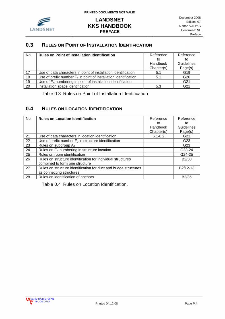
0.3 RULES ON POINT OF INSTALLATION IDENTIFICATION
No. Rules on Point of Installation Identification Reference to
Handbook Chapter(s)
Reference to
Guidelines Page(s)
17 Use of data characters in point of installation identification 5.1 G19 18 Use of prefix number F0 in point of installation identification 5.1 G20 19 Use of FN numbering in point of installation identification G21 20 Installation space identification 5.3 G21
Table 0.3 Rules on Point of Installation Identification.
0.4 RULES ON LOCATION IDENTIFICATION
No. Rules on Location Identification
Reference to
Handbook Chapter(s)
Reference to
Guidelines Page(s)
21 Use of data characters in location identification 6.1-6.2 G21 22 Use of prefix number F0 in structure identification G23 23 Rules on subgroup A3 G23 24 Rules on FN numbering in structure location G23-24 25 Rules on room identification G24-25 26 Rules on structure identification for individual structures
combined to form one structure B2/30
27 Rules on structure identification for duct and bridge structures as connecting structures
B2/12-13
28 Rules on identification of anchors B2/35
Table 0.4 Rules on Location Identification.

PRINTED DOCUMENTS NOT VALID
LANDSNET KKS HANDBOOK
KKS
December 2008
Edition: 07 Author: VAO/KS
Confirmed: NL Chapter 1
VERKFRÆÐISTOFANAFL OG ORKA
Printed 04.12.08 Page 1.1
1. KKS 2
1.1 SCOPE OF KKS 2 1.1.1 TYPE OF CODE 2 1.1.2 BREAK DOWN LEVELS, PREFIX AND BREAKDOWN SYMBOLS 4 1.1.3 KKS CODE 5 1.2 CONTENTS OF DATA CHARACTERS 5 1.2.1 BREAK DOWN LEVEL ÷1 5 1.2.2 BREAK DOWN LEVEL 0 8 1.2.3 BREAK DOWN LEVEL 1 9 1.2.4 BREAK DOWN LEVEL 2 11 1.2.5 BREAK DOWN LEVEL 3 12

PRINTED DOCUMENTS NOT VALID
LANDSNET KKS HANDBOOK
KKS
December 2008
Edition: 07 Author: VAO/KS
Confirmed: NL Chapter 1
VERKFRÆÐISTOFANAFL OG ORKA
Printed 04.12.08 Page 1.2
1. KKS
1.1 SCOPE OF KKS
The Identification System for Power Plants “KKS” serves to identify Power Plants, sections of plants and items of equipment in any kind of Power Plants according to task, type and location. It also serves to identify Sub Stations and overhead lines in the same manner. The KKS key is based on the IEC and ISO standards together with the DIN 40719 PART 2 (IEC 750). These KKS guidelines do not contain rules on:
• Combination of the code with other identification systems.
• Methods of marking, e.g. in control rooms, local control stations, labelling off components and identification of documents.
• Open text abbreviations.
• Identification/numbering of drawings. The following guidelines and explanations issued by VGB are valid, and where not in contradiction to the handbook, they do apply.
• KKS Guidelines (4th edition 1995)
• KKS-Application Commentaries, Part A General (1st edition 1988)
• KKS-Application Commentaries, Part B Engineering Discipline, Part B1, Identification in Mechanical Engineering (1st edition 1988)
• KKS-Application Commentaries, Part B Engineering Discipline, Part B2, Identification in Civil Engineering (1st edition 1988)
• KKS-Application Commentaries, Part B Engineering Discipline, Part B3, Identification in Electrical and Control and Instrumentation Engineering (1st edition 1988)
• KKS-Application Commentaries, Part B Engineering Discipline, Part B4, Identification in Electrical and Control and Instrumentation Engineering (1st edition 1993)
1.1.1 TYPE OF CODE
The KKS has three different types of codes, which can be used together or separately. These codes are the process-related code, the point of installation code and the location code. These codes are subdivided into 3 and 4 Break Down Levels (BDL).

PRINTED DOCUMENTS NOT VALID
LANDSNET KKS HANDBOOK
KKS
December 2008
Edition: 07 Author: VAO/KS
Confirmed: NL Chapter 1
VERKFRÆÐISTOFANAFL OG ORKA
Printed 04.12.08 Page 1.3
Process related Code
Process related identification of systems and items of equipment according to their function in mechanical, civil, electrical and control and instrumentation engineering. As example there are pipes, pumps, valves, motors, measurements, switches, transformers etc.
Point of installation Code
Identification of points of installation of electrical and control and instrumentation equipment in installation units e.g. in cabinets, panels, consoles etc.
Location Code
Identification of various structures, such as dams, tunnels, buildings, floors, and rooms and fire areas. This code is also used in connection with preventive maintenance of buildings and structures. Further more this code is used to identify the location of mechanical components in the same manner as the point of installation code is used in electrical- and control and instrumentation engineering.

PRINTED DOCUMENTS NOT VALID
LANDSNET KKS HANDBOOK
KKS
December 2008
Edition: 07 Author: VAO/KS
Confirmed: NL Chapter 1
VERKFRÆÐISTOFANAFL OG ORKA
Printed 04.12.08 Page 1.4
1.1.2 BREAK DOWN LEVELS, PREFIX AND BREAKDOWN SYMBOLS
Definitions for prefixes and breakdown symbols for writing these codes are in DIN 40719, part 2. The following fig. 1.1 shows the role of the codes on different BDL´s.
PART OFA PLANT
SYSTEM EQUIPMENT COMPONENT=
INSTALLATION INSTALLATION+
STRUCTURE ROOM+
0 1 2 3
Prefix Breakdownsymbol symbol
CODE UNIT CODE CODE
UNIT CODE SPACE CODE
CODE CODE
Process
Point of
Location
BDL
related
installation
identification
identification
identification
PART OFA PLANT
PART OFA PLANT
AREA /TOTAL PLANT
-1
AREA /TOTAL PLANT
AREA /TOTAL PLANT
Fig. 1.1 Break Down Levels for various types of codes
The “full stop” breakdown symbol for point of installation identification must always be written. The prefix symbols may be omitted if the information content of the codes remains unambiguous.
In front of these codes there is a BDL ÷1 and this BDL is used for identification of Power Plants and Sub Stations. It does not belong to the KKS code issued by VGB, but has been decided upon by Landsnet, (see table 1.1 - 1.4). As an example the following is mentioned:
BDL Area Example KKS ÷1 Sub Station Teigarhorn S.S. TEH 0 Part of a S.S. Line 132 kV to HOL HO1 1 System Line bay 132 kV 1AEL10 2 Equipment (part of system) Circuit breaker GS100 3 Component (part of equipment) A fuse -F01
Table 1.1 Example, use of Break Down Levels.

PRINTED DOCUMENTS NOT VALID
LANDSNET KKS HANDBOOK
KKS
December 2008
Edition: 07 Author: VAO/KS
Confirmed: NL Chapter 1
VERKFRÆÐISTOFANAFL OG ORKA
Printed 04.12.08 Page 1.5
1.1.3 KKS CODE
The KKS code consists of alpha letters (A) and numbers (N). The code is divided in 4 (0-3) BDL´s in the process related code and in 3 (0-2) BDL´s in the point of installation code and the location code. BDL 0 1 2 3
Definition Part of a plant System code Equipment unit code Component code
Name G F0 F1 F2 F3 FN A1 A2 AN A3 B1 B2 BN
Type of key
A/N A/N A/N N A A A N N A A N N N A A A N N
Table 1.2 KKS codes.
1.2 CONTENTS OF DATA CHARACTERS
It shall be clearly stated that all explanations in this book are related to the process code unless otherwise specified. In the KKS key the use of the alpha symbols (A) is defined in most cases. Still there are some codes that are available for free use, see chapters 4.10. The definition of the use of numerical symbols (N) is defined in this book, according to the regulations valid by Landsnet. The letters I and O are not permitted on BDL 1, 2 and 3 in the KKS code, to avoid misunderstanding between I and 1 (one) on one hand and O and 0 (zero) on the other hand. The Icelandic alphabetic characters Á, Ð, É, Í, Ó, Ú, Ý, Þ, Æ and Ö are not permitted and only capital letters are allowed.
1.2.1 BREAK DOWN LEVEL ÷÷÷÷1
BDL ÷ 1
Definition Area / Total plant
Name S1 S2 S3
Type of key A A A/N
Table 1.3 BDL ÷1
The BDL ÷1 is used for definition of names of areas or constructions, which are to be coded. This BDL is free for use, so the short names of the Power Plants and Sub Stations are used for identification. If more than one Power Plant is using the same water impounding works, they have the same name on this BDL.
Normally alpha symbols are used on BDL ÷1 and they occupy 3 places.
PRINTED DOCUMENTS NOT VALID
LANDSNET KKS HANDBOOK
KKS
December 2008
Edition: 07 Author: VAO/KS
Confirmed: NL Chapter 1
VERKFRÆÐISTOFANAFL OG ORKA
Printed 04.12.08 Page 1.6
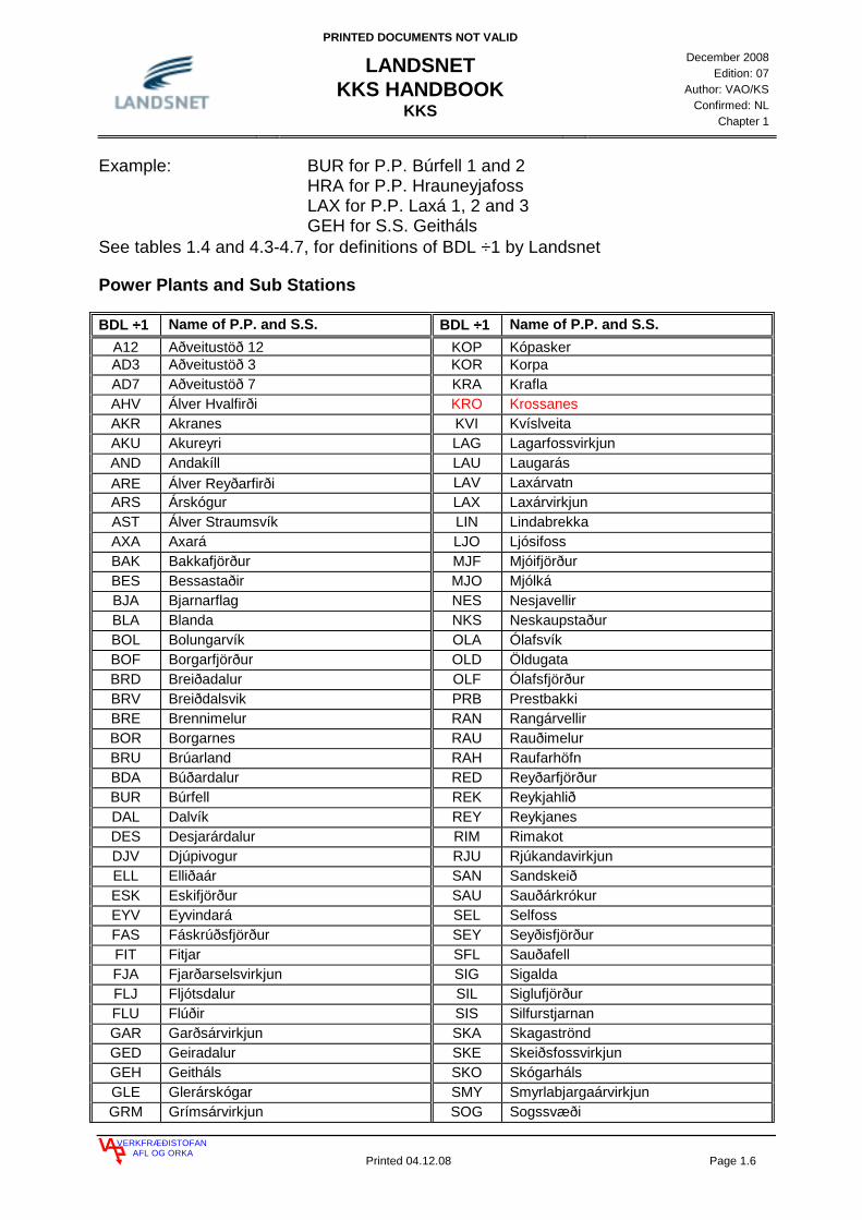
Example: BUR for P.P. Búrfell 1 and 2 HRA for P.P. Hrauneyjafoss LAX for P.P. Laxá 1, 2 and 3 GEH for S.S. Geitháls See tables 1.4 and 4.3-4.7, for definitions of BDL ÷1 by Landsnet
Power Plants and Sub Stations
BDL ÷÷÷÷1 Name of P.P. and S.S. BDL ÷÷÷÷1 Name of P.P. and S.S. A12 Aðveitustöð 12 KOP Kópasker AD3 Aðveitustöð 3 KOR Korpa AD7 Aðveitustöð 7 KRA Krafla AHV Álver Hvalfirði KRO Krossanes AKR Akranes KVI Kvíslveita AKU Akureyri LAG Lagarfossvirkjun AND Andakíll LAU Laugarás ARE Álver Reyðarfirði LAV Laxárvatn ARS Árskógur LAX Laxárvirkjun AST Álver Straumsvík LIN Lindabrekka AXA Axará LJO Ljósifoss BAK Bakkafjörður MJF Mjóifjörður BES Bessastaðir MJO Mjólká BJA Bjarnarflag NES Nesjavellir BLA Blanda NKS Neskaupstaður BOL Bolungarvík OLA Ólafsvík BOF Borgarfjörður OLD Öldugata BRD Breiðadalur OLF Ólafsfjörður BRV Breiðdalsvik PRB Prestbakki BRE Brennimelur RAN Rangárvellir BOR Borgarnes RAU Rauðimelur BRU Brúarland RAH Raufarhöfn BDA Búðardalur RED Reyðarfjörður BUR Búrfell REK Reykjahlið DAL Dalvík REY Reykjanes DES Desjarárdalur RIM Rimakot DJV Djúpivogur RJU Rjúkandavirkjun ELL Elliðaár SAN Sandskeið ESK Eskifjörður SAU Sauðárkrókur EYV Eyvindará SEL Selfoss FAS Fáskrúðsfjörður SEY Seyðisfjörður FIT Fitjar SFL Sauðafell FJA Fjarðarselsvirkjun SIG Sigalda FLJ Fljótsdalur SIL Siglufjörður FLU Flúðir SIS Silfurstjarnan GAR Garðsárvirkjun SKA Skagaströnd GED Geiradalur SKE Skeiðsfossvirkjun GEH Geitháls SKO Skógarháls GLE Glerárskógar SMY Smyrlabjargaárvirkjun GRM Grímsárvirkjun SOG Sogssvæði

PRINTED DOCUMENTS NOT VALID
LANDSNET KKS HANDBOOK
KKS
December 2008
Edition: 07 Author: VAO/KS
Confirmed: NL Chapter 1
VERKFRÆÐISTOFANAFL OG ORKA
Printed 04.12.08 Page 1.7
GRU Grundarfjörður STE Steingrímsstöð GON Gönguskarðsvirkjun STH Stóra-Hraun HAG Hágöngur STJ Bústaðavegur HAM Hamranes STR Straumsvík HEL Hellisheiðarvirkjun STU Stuðlar HLA Hella STY Stykkishólmur HNO Hnoðraholt STO Stöðvarfjörður HOS Hofsós SUL Sultartangi HOL Hólar SVA Svartsengi HRA Hrauneyjafoss SVE Sveinsstaðir HRS Hrísey TEH Teigarhorn HRF Hrútafell TEI Teigsbjarg HRU Hrútatunga TGA Tunga HRY Hryggstekkur TIN Þingvallastræti HUS Húsavik TOH Þórshöfn HVT Hvammstangi TOR Þorlákshöfn HVA Hvammur TVM Þórisvatnsmiðlun HVE Hveragerði UFS Ufsárlón HVO Hvolsvöllur URR Urriðafoss HOF Höfn VAF Vatnsfell IRA Írafoss VAR Varmahlíð ISA Ísafjörður VAT Vatnshamrar JAR Járnblendi VEG Vegamót KAL Kaldakvísl VEM Vestmannaeyjar KEL Keldeyri VIK Vík KOG Kollugerði VOG Vogaskeið KOL Kolviðarhóll VOP Vopnarfjörður
Table 1.4 Definition of BDL ÷1 for Power Plants and Sub Stations.
BDL ÷÷÷÷1 Name of P.P. and S.S. BDL ÷÷÷÷1 Name of P.P. and S.S. ABA Álver á Bakka HVH Hverahlíð AHE Álver Helguvík KUA Kúagerði BIT Bitra NJA Njarðvíkurheiði BUD Búðarháls OLK Ölkelduháls GJA Gjástykki SAF Sandfell GRD Grændalur SET Seltún HEH Hellisheiði TRD Trölladyngja HLT Holt TRE Þeistareykir HRT Hrauntungur URR Urriðafoss HSA Hólasandur VAL Vallarheiði
Table 1.5 Expected definition of BDL ÷1 for Power Plants and Sub Stations.

PRINTED DOCUMENTS NOT VALID
LANDSNET KKS HANDBOOK
KKS
December 2008
Edition: 07 Author: VAO/KS
Confirmed: NL Chapter 1
VERKFRÆÐISTOFANAFL OG ORKA
Printed 04.12.08 Page 1.8
1.2.2 BREAK DOWN LEVEL 0
BDL 0 1 2 3
Definition Part of a plant System code Equipment unit code Component code
Name G F0 F1 F2 F3 FN A1 A2 AN A3 B1 B2 BN
Type of key
A/N A/N A/N N A A A N N A A N N N A A A N N
Table 1.6 BDL 0.
The KKS key allows the use of alpha- and numerical symbols on BDL 0. In case of one Power Plant with its own water impounding works, BDL 0 is defined as zero and written 000. When more than one Power Plant shares the same water impounding works (W.I.W), the W.I.W. get a 000 (zero) on BDL 0 and each station is numbered, so that the oldest one gets the number 001 the next one 002 etc. Common equipment for two or more stations will always receive the number 000. Example:
Fig. 1.2 Example of use of BDL 0.
BDL ÷1000
001
002
All common equipment forLaxárstöðvar power plantExample: W:I:W. for
LAX
LAX
LAX
BDL 0
Laxárstöð1
Laxárstöð 2
All equipment for
All equipment for
Laxá 1, 2 og 3
PRINTED DOCUMENTS NOT VALID
LANDSNET KKS HANDBOOK
KKS
December 2008
Edition: 07 Author: VAO/KS
Confirmed: NL Chapter 1
VERKFRÆÐISTOFANAFL OG ORKA
Printed 04.12.08 Page 1.9
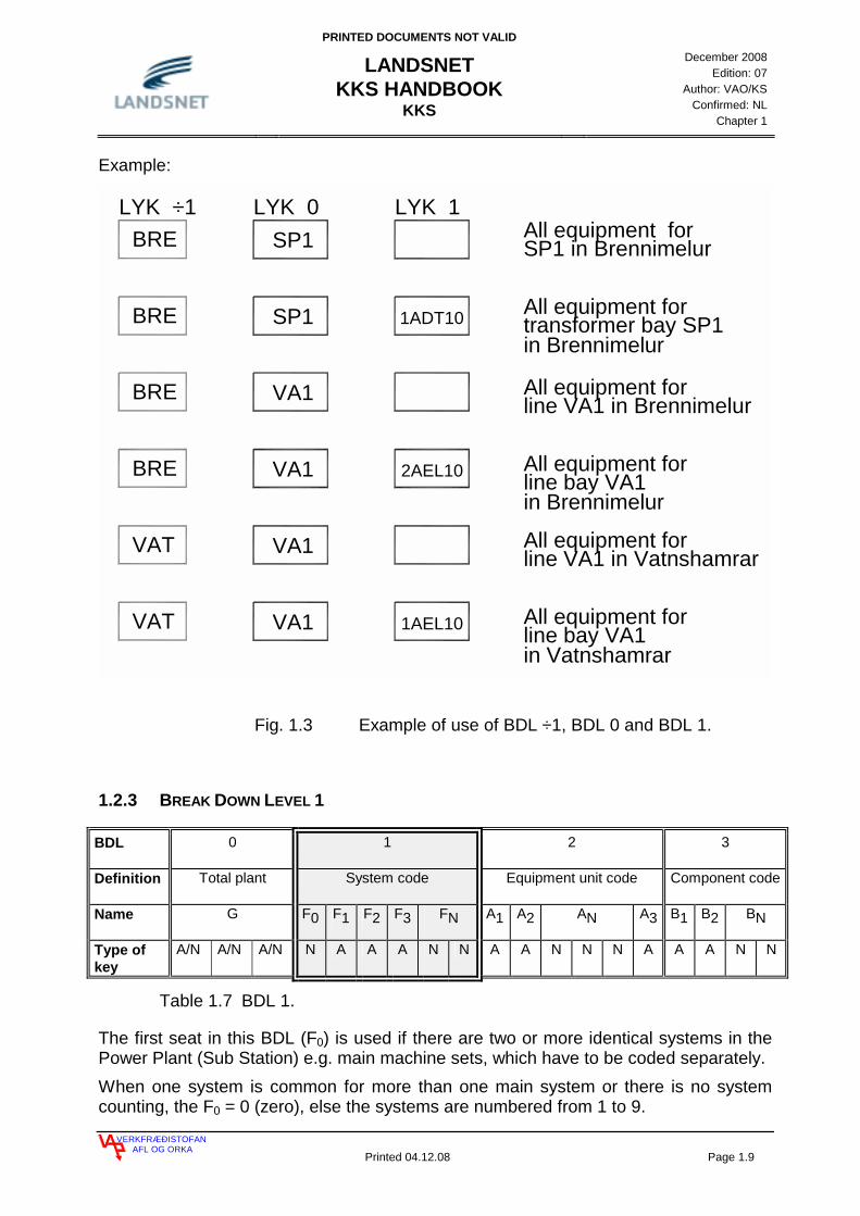
Example:
LYK ÷1SP1
VA1
BRE
BRE
LYK 0
line VA1 in BrennimelurAll equipment for
All equipment for SP1 in Brennimelur
LYK 1
BRE VA1
BRE SP1
line bay VA1in Brennimelur
All equipment for2AEL10
transformer bay SP1in Brennimelur
All equipment for1ADT10
1AEL10VAT
VAT
VA1
VA1
in Vatnshamrarline bay VA1
line VA1 in Vatnshamrar
All equipment for
All equipment for
Fig. 1.3 Example of use of BDL ÷1, BDL 0 and BDL 1.
1.2.3 BREAK DOWN LEVEL 1
BDL 0 1 2 3
Definition Total plant System code Equipment unit code Component code
Name G F0 F1 F2 F3 FN A1 A2 AN A3 B1 B2 BN
Type of key
A/N A/N A/N N A A A N N A A N N N A A A N N
Table 1.7 BDL 1.
The first seat in this BDL (F0) is used if there are two or more identical systems in the Power Plant (Sub Station) e.g. main machine sets, which have to be coded separately. When one system is common for more than one main system or there is no system counting, the F0 = 0 (zero), else the systems are numbered from 1 to 9.

PRINTED DOCUMENTS NOT VALID
LANDSNET KKS HANDBOOK
KKS
December 2008
Edition: 07 Author: VAO/KS
Confirmed: NL Chapter 1
VERKFRÆÐISTOFANAFL OG ORKA
Printed 04.12.08 Page 1.10
G
G
G
3MAA 3MAB 3MAC 3MKA
STEAM TURBINE PLANT
UNIT 1
UNIT 2
UNIT 3
COMMONSYSTEMS
0MAC
2MAA 2MAB 2MAC 2MKA
1MAA 1MAB 1MAC 1MKA
Fig. 1.4 Example of use of F0 on BDL 1.
On this BDL (F1, F2, F3) the original KKS key applies. Some keys (F2, F3) in this group are given free for use so that they can be used as it suits the purpose of coding. This also applies to some keys on BDL 2 (A2) and on BDL 3 (B2). Some keys (F3) in the group of ancillary systems are given free for use to separate systems in various buildings. The use of these characters has been defined by Landsnet, and this is shown in chapter 3. and chapter 4. It is not permitted to use keys that are “blocked” in the code. They cannot be used under any circumstances. These keys are blocked for future use. The FN numbers are used for coding within the same system. As an example the main code for a generator rotor is MKA 20 and for a generator stator the main code is MKA 40.

PRINTED DOCUMENTS NOT VALID
LANDSNET KKS HANDBOOK
KKS
December 2008
Edition: 07 Author: VAO/KS
Confirmed: NL Chapter 1
VERKFRÆÐISTOFANAFL OG ORKA
Printed 04.12.08 Page 1.11
1.2.4 BREAK DOWN LEVEL 2
BLD 0 1 2 3
Definition Part of a plant System code
Equipment unit code Component code
Name G F0 F1 F2 F3 FN A1 A2 AN A3 B1 B2 BN
Type of key
A/N A/N A/N N A A A N N A A N N N A A A N N
Table 1.8 BDL 2.
In the KKS key equipment is coded/defined by A1, A2 e.g. valves, pumps, switches etc.. The AN number is a consecutive number which is used to number identical equipment, which is identified by A1, A2, within the same system. It has been decided by Landsnet how these numbers shall be used in case of parallel- and serial connected systems in the mechanical engineering and also in the electrical part, where 3 phase systems are coded and A3 is used to separate e.g. cores in measurement transformers see chapter 4. When A3 is not used, it is not written in the code.
G2MKA00
2BAA022MKC102BAA02
2MKC10
2MKC10
2BAA01
G1MKA00
1BAA021MKC101BAA02
1MKC10
1MKC10
1BAA01
UNIT 1 UNIT 2
CE200
CE100GT100
CE100
GU100
CE100
CE200
CE100GT100
CE100
GU100
CE100
1MKC10GS 100
2MKC10GS100
Fig. 1.5 Example of use of AN numbers on BDL 2. Two identical systems. The AN numbers are the same in both cases, see chapters 3. and 4.
PRINTED DOCUMENTS NOT VALID
LANDSNET KKS HANDBOOK
KKS
December 2008
Edition: 07 Author: VAO/KS
Confirmed: NL Chapter 1
VERKFRÆÐISTOFANAFL OG ORKA
Printed 04.12.08 Page 1.12
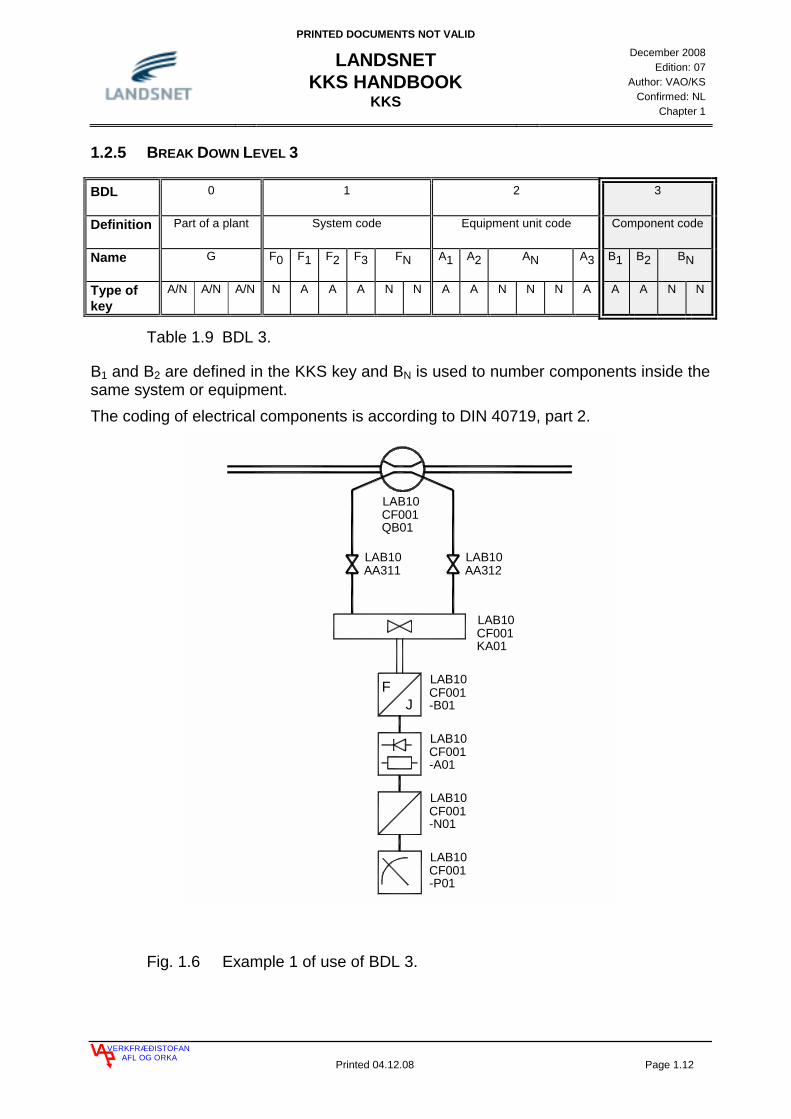
1.2.5 BREAK DOWN LEVEL 3
BDL 0 1 2 3
Definition Part of a plant System code Equipment unit code Component code
Name G F0 F1 F2 F3 FN A1 A2 AN A3 B1 B2 BN
Type of key
A/N A/N A/N N A A A N N A A N N N A A A N N
Table 1.9 BDL 3.
B1 and B2 are defined in the KKS key and BN is used to number components inside the same system or equipment. The coding of electrical components is according to DIN 40719, part 2.
FJ
LAB10CF001
LAB10AA311
LAB10AA312
QB01
LAB10CF001KA01
LAB10CF001-B01
LAB10CF001-A01
LAB10CF001-N01
LAB10CF001-P01
Fig. 1.6 Example 1 of use of BDL 3.
PRINTED DOCUMENTS NOT VALID
LANDSNET KKS HANDBOOK
KKS
December 2008
Edition: 07 Author: VAO/KS
Confirmed: NL Chapter 1
VERKFRÆÐISTOFANAFL OG ORKA
Printed 04.12.08 Page 1.13
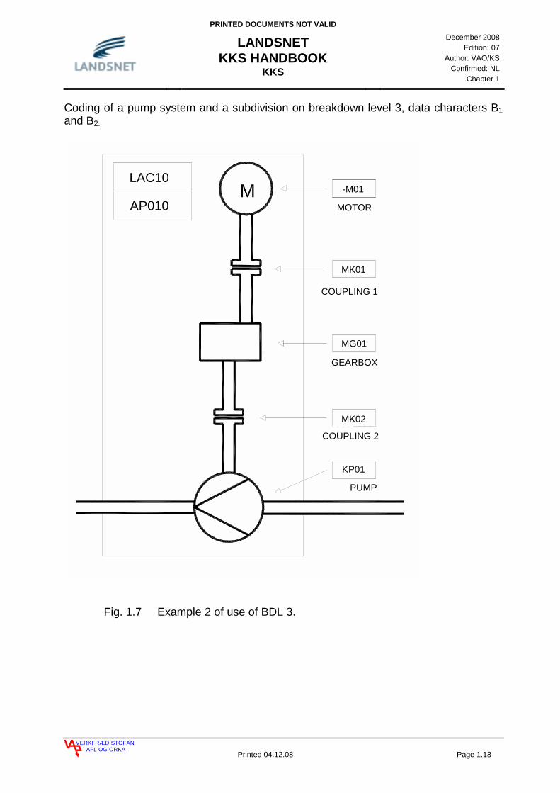
Coding of a pump system and a subdivision on breakdown level 3, data characters B1 and B2.
Fig. 1.7 Example 2 of use of BDL 3.
LAC10
AP010M -M01
MK01
MG01
MK02
KP01
COUPLING 2
PUMP
MOTOR
COUPLING 1
GEARBOX

PRINTED DOCUMENTS NOT VALID
LANDSNET KKS HANDBOOK
KKS
December 2008
Edition: 07 Author: VAO/KS
Confirmed: NL Chapter 1
VERKFRÆÐISTOFANAFL OG ORKA
Printed 04.12.08 Page 1.14
Fig. 1.8 Example of coding according to the process related code.
= LAC21
= LAC21
= LAC21
= LAC21
CODING OF A PUMP SYSTEM
= PREFIX SYMBOL FOR PROCESS RELATED CODE
CHA01 CHA02
BBC 01
0302
AP010
AP010
AP010
AP010
PRINTED DOCUMENTS NOT VALID
LANDSNET KKS HANDBOOK
KKS
December 2008
Edition: 07 Author: VAO/KS
Confirmed: NL Chapter 1
VERKFRÆÐISTOFANAFL OG ORKA
Printed 04.12.08 Page 1.15
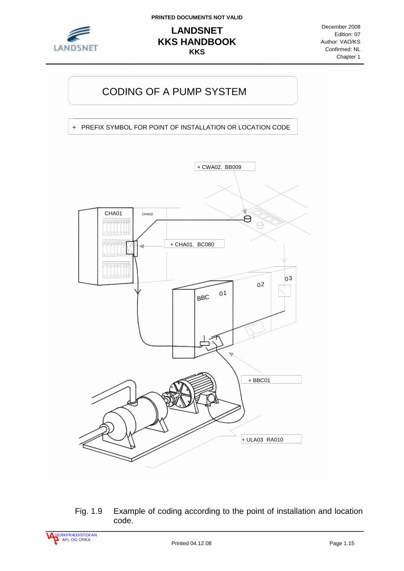
Fig. 1.9 Example of coding according to the point of installation and location code.
+ CWA02.
+ CHA01.
+ ULA03
+ BBC01
CODING OF A PUMP SYSTEM
+ PREFIX SYMBOL FOR POINT OF INSTALLATION OR LOCATION CODE
CHA01 CHA02
BBC 01
0302
BB009
BC080
RA010

PRINTED DOCUMENTS NOT VALID
LANDSNET KKS HANDBOOK
KKS
December 2008
Edition: 07 Author: VAO/KS
Confirmed: NL Chapter 1
VERKFRÆÐISTOFANAFL OG ORKA
Printed 04.12.08 Page 1.16
Fig. 1.10 Example of coding according to the process related, point of installation and location code.
= LAC21
= LAC21
= LAC21
+ BBC01
CODING OF A PUMP SYSTEM
+ PREFIX SYMBOL FOR PROCESS RELATED CODE
+ PREFIX SYMBOL FOR POINT OF INSTALLATION OR LOCATION CODE
CHA01 CHA02
BBC 0 1
0 30 2
+ CWA02.
+ CHA01.
= LAC21
+ ULA03
AP010
AP010
AP010
BB009
BC080
AP010
RA010
PRINTED DOCUMENTS NOT VALID
LANDSNET KKS HANDBOOK
NUMBERING
December 2008
Edition: 07 Author: VAO/KS
Confirmed: NL Chapter 2
VERKFRÆÐISTOFANAFL OG ORKA
Printed 04.12.08, 10:16 Page 2.1
2 NUMBERING 2
2.1 FN NUMBERING 4 2.2 AN NUMBERING 5 2.2.1 NUMBERING OF PIPING SYSTEMS 5 2.2.2 NUMBERING OF VALVES 6 2.2.3 AN NUMBERING OF VALVES IN COOLING SYSTEMS 9 2.2.4 EQUIPMENT NUMBERING 10 2.2.5 NUMBERING OF MEASUREMENT POINTS 11

PRINTED DOCUMENTS NOT VALID
LANDSNET KKS HANDBOOK
NUMBERING
December 2008
Edition: 07 Author: VAO/KS
Confirmed: NL Chapter 2
VERKFRÆÐISTOFANAFL OG ORKA
Printed 04.12.08, 10:16 Page 2.2
2 NUMBERING
The KKS code allows a certain possibility of free/individual use of numbering code elements. This chapter shows the rules for using the FN and the AN numbers. The rules defined here are binding for the KKS coding for Landsnet. In some cases it is possible to use some other way of numbering, in those cases the Landsnet’s KKS committee will set the standard for that numbering. The source for this are the KKS Guidelines from VGB, together with Part A and Part B (booklets B1, B2, B3 and B4) also from VGB. 1. Numbering starts again when one of the preceding code elements changes. 2. Numbering may be done in units or decades. It depends on the system that’s
being used. 3. Numbering is as a rule in the direction of flow. 4. Numbering shall be from left to right or from top to bottom. It is permitted to use
numbering that exists in old Power Plants though it isn’t in the right direction. 5. It is preferred to use gaps in the numbering, to simplify later changes. The numbering with FN and AN shall always be in the direction of a flow as often as possible. If however the flow has two directions, one direction shall be defined as “NORMAL OPERATION”. The “flag” symbol represents codes for pipes. A “flag” with one leg points in the direction of flow while a “flag” with two legs indicates that the flow can be in both directions, depending on the mode of operation.
PRINTED DOCUMENTS NOT VALID
LANDSNET KKS HANDBOOK
NUMBERING
December 2008
Edition: 07 Author: VAO/KS
Confirmed: NL Chapter 2
VERKFRÆÐISTOFANAFL OG ORKA
Printed 04.12.08, 10:16 Page 2.3
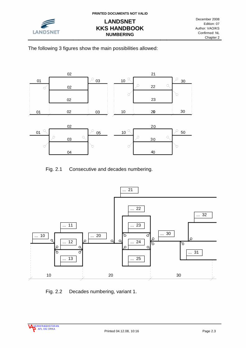
The following 3 figures show the main possibilities allowed:
Fig. 2.1 Consecutive and decades numbering.
... 10
... 11
... 12
... 13
... 20
... 22
... 23
... 25
... 24
... 21
... 30
... 32
... 31
10 20 30
Fig. 2.2 Decades numbering, variant 1.
01
02
02
02
03 10
21
22
23
30
0102
03
04
05 102
3
4
01 03 10 2002 30
50
0
0
0
0

PRINTED DOCUMENTS NOT VALID
LANDSNET KKS HANDBOOK
NUMBERING
December 2008
Edition: 07 Author: VAO/KS
Confirmed: NL Chapter 2
VERKFRÆÐISTOFANAFL OG ORKA
Printed 04.12.08, 10:16 Page 2.4
... 10
... 21
... 22
... 23
... 30
... 41
... 42
... 44
... 43
... 31
... 50
... 52
... 51
10 20 30 40 50
Fig. 2.3 Decades numbering, variant 2.
Numbering in decades is convenient for large systems. Each case shall be treated uniquely depending to how the system is built when decades numbering is used. Decades numbering shall be used in main and extensive systems, but sub-systems shall be numbered using units. Consecutive numbering shall only be used within the same system or within the same part of a system where components are in parallel connection.
2.1 FN NUMBERING
FN numbering is used to divide systems in parts or subsystems. FN is done in decades (10,20,30....etc.) or consecutive (11,12,13,14......etc) FN numbering should be minimised. If no further FN numbering is needed then the decade 10 should be used in the FN seat. Numbering with FN in large plumbing systems should be clearly divided, e.g. by areas, by levels, by machinery and by large parts of machinery with decade numbering but with consecutive numbering in parallel connected system. Example of FN numbering is found in chapter 3, Identification in mechanical engineering. Upper and lower guide valves are numbered in decades (10,20,30 ...) but individual parts of the guide valves are numbered consecutively (11,12,13 ...).

PRINTED DOCUMENTS NOT VALID
LANDSNET KKS HANDBOOK
NUMBERING
December 2008
Edition: 07 Author: VAO/KS
Confirmed: NL Chapter 2
VERKFRÆÐISTOFANAFL OG ORKA
Printed 04.12.08, 10:16 Page 2.5
2.2 AN NUMBERING
AN numbering is used to divide systems in single parts. AN numbering shall be in decades (_10, _20, _30 ….) or in consecutive (_11, _12, _13 …..). For numbering of electrical and pipe line systems separations shall be clear. E.g. use decade numbering for separation along main branches and use consecutive numbering for separation along parallel connected branches.
2.2.1 NUMBERING OF PIPING SYSTEMS
Normally, pipes are not coded, but where needed e.g. in Thermal Power Plants, the following rules shall be used: Decades numbering shall be used for the identification of main piping systems, 010, 020, 030...., e.g. when the role/function changes, e.g. when pressure, temperature etc. change. Consecutive numbering shall be used for sub-piping systems e.g. bypass, pipes for control valves etc. which receive the numbering 011, 012, 013..... or 021, 022, 023.... etc.. Consecutive numbering is also used for pipes for control circuits, air- and water drainage, instrument lines, sampling lines and safety lines. These are numbered with _01, _02, _03,...etc.. Attempt should be made to distinguish the pipes in a sub piping system from the pipes in the main piping system, e.g. first pipe in sampling line from main pipe 010, 020, 030 shall be numbered 411, 421, 431 etc. The numbering of the following pipes shall be grouped by counting in hundreds in the following way: 0 _ 0 for main piping system 0 _ _ for sub piping system 1 _ _ for control circuit piping 2 _ _ for drains and vents 3 _ _ for instrument lines (if numbered) 4 _ _ for sampling pipe lines 5 _ _ for safety line piping.

PRINTED DOCUMENTS NOT VALID
LANDSNET KKS HANDBOOK
NUMBERING
December 2008
Edition: 07 Author: VAO/KS
Confirmed: NL Chapter 2
VERKFRÆÐISTOFANAFL OG ORKA
Printed 04.12.08, 10:16 Page 2.6
M
MLAB50
BR010
LAB50
BR011
LAB50
BR020
LAB50
BR010LAB50AA 011
LAB50AA010
LAB50AA201
LAB50
BR201
LAB50
BR012
LAB50
BR202
Fig. 2.4 Numbering of piping systems, decades and hundreds.
2.2.2 NUMBERING OF VALVES
Decades numbering shall be used for valves in a main piping system, 010, 020, 030, etc. when their role/function changes, e.g. when pressure, temperature etc. change. In sub-piping systems, valves like bypass valves, control valves etc. shall be numbered 011, 012, 013.... or 021, 022, 023... etc. Consecutive numbering is also used for valves for control circuits, air- and water drainage, instrument valves, sampling valves and safety valves. They are numbered with _01, _02, _11,_12,...etc. It is preferred to number valves from valve in main plumbing system, e.g. the first valve in sampling system from a valve in the main plumbing system 010, 020, 030, should be numbered 411, 421, 431 etc. The numbering of the following valves shall be grouped by counting in hundreds in the following way: 0 _ 0 for valves in main piping system 0 _ _ for valves in sup piping system 1 _ _ for control valves 2 _ _ for valves in drains and vents 3 _ _ for isolation valves in instrument lines 4 _ _ for valves in sampling lines 5 _ _ for valves in security lines

PRINTED DOCUMENTS NOT VALID
LANDSNET KKS HANDBOOK
NUMBERING
December 2008
Edition: 07 Author: VAO/KS
Confirmed: NL Chapter 2
VERKFRÆÐISTOFANAFL OG ORKA
Printed 04.12.08, 10:16 Page 2.7
M
LAB50AA022
LAB50AA020
LAB50AA010
LAB50AA110
LAB50AA011
LAB50AA021
LAB50AA032
LAB50AA030
LAB50AA031
LAB50AA211
Fig. 2.5 Numbering of valves, in decades and hundreds. Main branch. Drainage of main branch. Sub branches.

PRINTED DOCUMENTS NOT VALID
LANDSNET KKS HANDBOOK
NUMBERING
December 2008
Edition: 07 Author: VAO/KS
Confirmed: NL Chapter 2
VERKFRÆÐISTOFANAFL OG ORKA
Printed 04.12.08, 10:16 Page 2.8
M
LAB50AA021
LAB50AA041
LAB50AA211
LAB50AA010
LAB50AA110
LAB50AA011
LAB50AA031
LAB50AA022
LAB50AA042
LAB50AA032
LAB50AA061
LAB50AA062
M
M
M
LAB50AA051
LAB50AA052
M
Fig. 2.6 Numbering of valves in decades and hundreds, main system, draining of main valve and dividing in sub systems.

PRINTED DOCUMENTS NOT VALID
LANDSNET KKS HANDBOOK
NUMBERING
December 2008
Edition: 07 Author: VAO/KS
Confirmed: NL Chapter 2
VERKFRÆÐISTOFANAFL OG ORKA
Printed 04.12.08, 10:16 Page 2.9
2.2.3 AN NUMBERING OF VALVES IN COOLING SYSTEMS
Valves are numbered as described in chapter 2.2.2. In all cooling systems, the heat exchanger belongs to the circulating system.
PGA10AC010
PGA10AA010
PCA10AA020
PGA10AA070
PGA10AP010
PCA10AA221
PCA10AA222
PGA10AA 211CP201
PCA10AT010
PCA10AA211
PCA10AA212
PCA10AA011
CP101
CP101
PGA10AA351
PGA10AA352
PCA10AA021
PCA10
PGA10
PGA10
AA020PGA10
PGA10AA050
AA010PCA10
Fig. 2.7 Numbering of measurements, equipment and components, e.g. in a cooling system.
PRINTED DOCUMENTS NOT VALID
LANDSNET KKS HANDBOOK
NUMBERING
December 2008
Edition: 07 Author: VAO/KS
Confirmed: NL Chapter 2
VERKFRÆÐISTOFANAFL OG ORKA
Printed 04.12.08, 10:16 Page 2.10
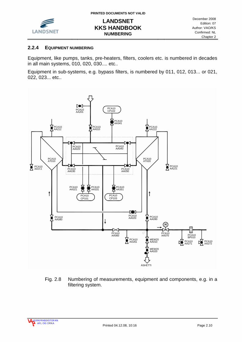
2.2.4 EQUIPMENT NUMBERING
Equipment, like pumps, tanks, pre-heaters, filters, coolers etc. is numbered in decades in all main systems, 010, 020, 030.... etc.. Equipment in sub-systems, e.g. bypass filters, is numbered by 011, 012, 013... or 021, 022, 023... etc..
PCA10AA080
PCA10AA211
ÁSÞÉTTI
CP101 CP103
PCA10AA050
PCA10AA030
PCA10AA040
PCA10AA020
PCA10AA212
PCA10AA222
PCA10AA010
PCA10AA341
CP102PCA10AA201
PCA10AT020
PCA10AA221
PCA10AA351
PCA10AA321
PCA10AA331
PCA10AT010
PCA10AA020 PCA10
AA090
PCA10AA261
MEW20AA020
MEW20AA010
PCA10BP010
PCA10AA070
PCA10AA271
PCA10AA272
PCA10 PCA10
PCA10
AA060PCA10
Fig. 2.8 Numbering of measurements, equipment and components, e.g. in a filtering system.

PRINTED DOCUMENTS NOT VALID
LANDSNET KKS HANDBOOK
NUMBERING
December 2008
Edition: 07 Author: VAO/KS
Confirmed: NL Chapter 2
VERKFRÆÐISTOFANAFL OG ORKA
Printed 04.12.08, 10:16 Page 2.11
2.2.5 NUMBERING OF MEASUREMENT POINTS
Measurement points numbering is consecutive and shall be grouped by the hundreds in the following way: 1 _ _ for indicating local meters, sight-glasses, meters with no control or alarm purpose and meters which are not connected to remote control 2 _ _ for digital meters with control and alarm purposes 3 _ _ for analog meters with control and alarm purposes.
M
LAB10AP010
-M01 MK02
KP02
LAB10
LAB10AA332
LAB10AT010
LAB10AA321
LAB10AA322
LAB10AA331
CT101
Co
20 6040
10 3020
MPa
10 3020
MPa
STJÓRNSKÁPUR
CP301LAB10
CP101LAB10
AA010LAB10
LAB10AA020
LAB10AA030
LAB10CT201
LAB10AA311
4440 ,
oC
STJÓRNSKÁPUR
Fig. 2.9 Numbering of measurements, equipment and components, e.g. in a feed water system.

PRINTED DOCUMENTS NOT VALID
LANDSNET KKS HANDBOOK
NUMBERING
December 2008
Edition: 07 Author: VAO/KS
Confirmed: NL Chapter 2
VERKFRÆÐISTOFANAFL OG ORKA
Printed 04.12.08, 10:16 Page 2.12
MLAE21BR010
LAE21AA010
LAE21AA021
LAE21AA030
LAE21BR011
LAE21BR012
BR020LAE21
LAE21AA020
LAE21AA301
LAE21
LAE21AA302
LAE21AA304
LAE21AA303
HAH21
LAE20BR010
MLAE23BR010
LAE23AA010
LAE23AA021
LAE23AA030
LAE23BR011
LAE23BR012
BR020LAE23
LAE 23AA020
LAE23AA301
LAE23AA302
LAE23AA304
LAE23AA303
HAH23
MLAE22BR010
LAE22AA010
LAE 22AA021
LAE22AA030
LAE22BR011
LAE22BR012
BR020LAE22
LAE22AA020
LAE 22AA301
LAE22AA302
LAE22AA304
LAE22AA303
HAH22
CF101
LAE22CF101
LAE23CF101
Fig. 2.10 Coding of pipes, valves, measurements and equipment, e.g. in a spraying system.

PRINTED DOCUMENTS NOT VALID
LANDSNET KKS HANDBOOK
MECHANICAL
December 2008
Edition: 07 Author: VAO/KS
Confirmed: NL Chapter 3
VERKFRÆÐISTOFANAFL OG ORKA
Printed 04.12.08, Page 3.1
3. IDENTIFICATION IN MECHANICAL ENGINEERING 2
3.1 WATER IMPOUNDING WORKS 2 3.1.1 CODING OF WATER IMPOUNDING WORKS 2 3.1.2 CODING OF GATE HYDRAULIC 4 3.1.3 CODING OF GATE HEATING SYSTEM 5 3.2 CODING OF TURBINES 6 3.2.1 FRANCIS TURBINE 6 3.2.2 KAPLAN TURBINE 7 3.2.3 PELTON TURBINE 9 3.2.4 CODING OF STEAM TURBINES 10 3.2.5 GOVERNOR OF A WATER TURBINE 12 3.3 CODING OF GENERATORS 13 3.4 CODING OF AIR-CONDITION SYSTEMS 14 3.5 CODING OF GEOTHERMAL POWER PLANTS 14
PRINTED DOCUMENTS NOT VALID
LANDSNET KKS HANDBOOK
MECHANICAL
December 2008
Edition: 07 Author: VAO/KS
Confirmed: NL Chapter 3
VERKFRÆÐISTOFANAFL OG ORKA
Printed 04.12.08, Page 3.2
3. IDENTIFICATION IN MECHANICAL ENGINEERING
3.1 WATER IMPOUNDING WORKS
3.1.1 CODING OF WATER IMPOUNDING WORKS
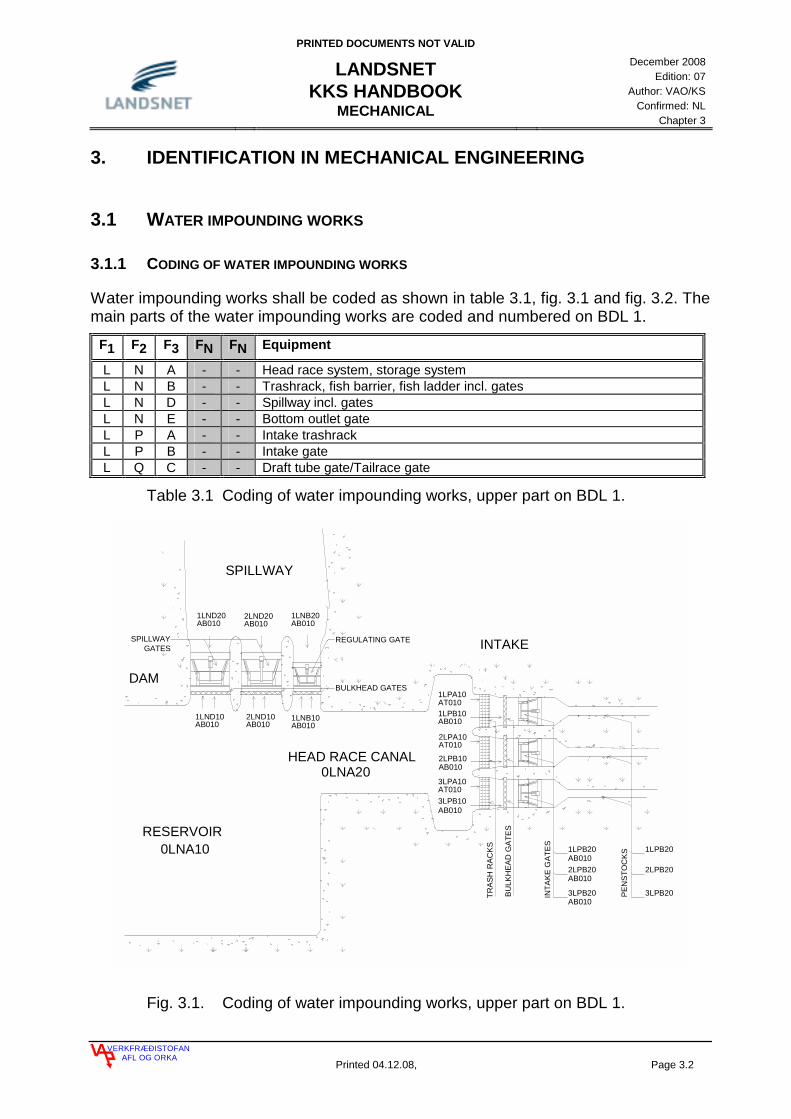
Water impounding works shall be coded as shown in table 3.1, fig. 3.1 and fig. 3.2. The main parts of the water impounding works are coded and numbered on BDL 1.
F1 F2 F3 FN FN Equipment
L N A - - Head race system, storage system L N B - - Trashrack, fish barrier, fish ladder incl. gates L N D - - Spillway incl. gates L N E - - Bottom outlet gate L P A - - Intake trashrack L P B - - Intake gate L Q C - - Draft tube gate/Tailrace gate
Table 3.1 Coding of water impounding works, upper part on BDL 1.
SPILLWAY
DAM
RESERVOIR
HEAD RACE CANAL
PE
NS
TOC
KS
INTA
KE
GA
TES
2LND20AB010
1LND20AB010
1LNB20AB010
0LNA20
3LPB10AB010
2LPB10AB010
1LPA10AT0101LPB10AB010
2LPA10AT010
3LPA10AT010
1LPB20AB0102LPB20AB010
3LPB20AB010
0LNA10
3LPB20
2LPB20
1LPB20
REGULATING GATE
BULKHEAD GATES
INTAKE
TRA
SH
RA
CK
S
BU
LKH
EA
D G
ATE
S
AB0102LND101LND10
AB0101LNB10AB010
SPILLWAYGATES
Fig. 3.1. Coding of water impounding works, upper part on BDL 1.

PRINTED DOCUMENTS NOT VALID
LANDSNET KKS HANDBOOK
MECHANICAL
December 2008
Edition: 07 Author: VAO/KS
Confirmed: NL Chapter 3
VERKFRÆÐISTOFANAFL OG ORKA
Printed 04.12.08, Page 3.3
1LPC 10
2LPC 10
3LPC 10
TAIL RACECANAL
1MEA 10
2MEA 10
3MEA 10
1LQA 10
1LQA 20
2LQA 10
2LQA 20
3LQA 10
3LQA 20
0LQA 10
1LQC 20
1LQC 10
2LQC 10
2LQC 20
3LQC 10
3LQC 20
PENSTOCKS TURBINES DRAFT TAIL RACETUBES
Fig. 3.2. Coding of water impounding works, lower part on BDL 1.

PRINTED DOCUMENTS NOT VALID
LANDSNET KKS HANDBOOK
MECHANICAL
December 2008
Edition: 07 Author: VAO/KS
Confirmed: NL Chapter 3
VERKFRÆÐISTOFANAFL OG ORKA
Printed 04.12.08, Page 3.4
3.1.2 CODING OF A GATE HYDRAULIC SYSTEM
The same FN numbering used for the gate shall be used for the gate hydraulic system (see fig. 3.3). The numbering for the gate hydraulic system shall be done as in fig 3.3. The main parts of the hydraulic system shall be coded on BDL 1.
LND20AS010LND20
AA212
LND20AA070
LND20AA211
LND20AA060
LND20AA351
LND20
LND20AA040
LND20AT030
LND20AA050
LND20AT010
LND20AA531
LND20AP030
LND20BB010
LND20BB020
LND20AA221
CL102CL202LND20
CG201LND20
CL201LND20
CP103LND20
CP201LND20
CP202LND20
CP104LND20
LND20AT020
LND20AP010 AA511
LND20
CP101LND20
AP020LND20
AA521LND20
CP102LND20
CT101LND20
CL101LND20
AA030LND20
AA010LND20 LND20
AA020
AA041LND20
LND20AA201
MM
Fig. 3.3. FN numbering of a gate hydraulic system.
PRINTED DOCUMENTS NOT VALID
LANDSNET KKS HANDBOOK
MECHANICAL
December 2008
Edition: 07 Author: VAO/KS
Confirmed: NL Chapter 3
VERKFRÆÐISTOFANAFL OG ORKA
Printed 04.12.08, Page 3.5
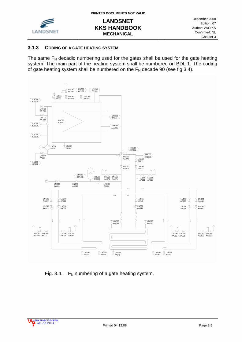
3.1.3 CODING OF A GATE HEATING SYSTEM
The same FN decadic numbering used for the gates shall be used for the gate heating system. The main part of the heating system shall be numbered on BDL 1. The coding of gate heating system shall be numbered on the FN decade 90 (see fig 3.4).
CP102LNC90
CF201LNC90
LNC90CT101
LNC90CP101
CT202LNC90
CT201LNC90
CP103LNC90
CT102LNC90
CT203LNC90
CQ101LNC90
CP104LNC90
AA 201LNC 90
AA 302LNC 90
AH010LNC90
AA203LNC90
AA303LNC90
AA501LNC90
AA204LNC90
AP010LNC90
AA202LNC90
AA301LNC90
AA010LNC90
AA070LNC90
AA012LNC90
LNC90AA011
AA211LNC90
AA212LNC90AA271AA272
LNC90 LNC90
AA094LNC90
LNC90BB090
LNC90AA040
AA093LNC90
AA091LNC90
AA030LNC90
AA031LNC90
AA021LNC90
AA020LNC90
AA221LNC90
AA222LNC90
AA231LNC90
AA232LNC90
AA223LNC90
AA233LNC90
AA243LNC90
AA241LNC90
AA242LNC90
AA041LNC90
AA253LNC90
AA263LNC90
LNC90AA050
LNC90AA051
LNC90AA061
LNC90AA060
LNC90AA262
LNC90AA261
LNC90AA252
LNC90AA251
Fig. 3.4. FN numbering of a gate heating system.
PRINTED DOCUMENTS NOT VALID
LANDSNET KKS HANDBOOK
MECHANICAL
December 2008
Edition: 07 Author: VAO/KS
Confirmed: NL Chapter 3
VERKFRÆÐISTOFANAFL OG ORKA
Printed 04.12.08, Page 3.6
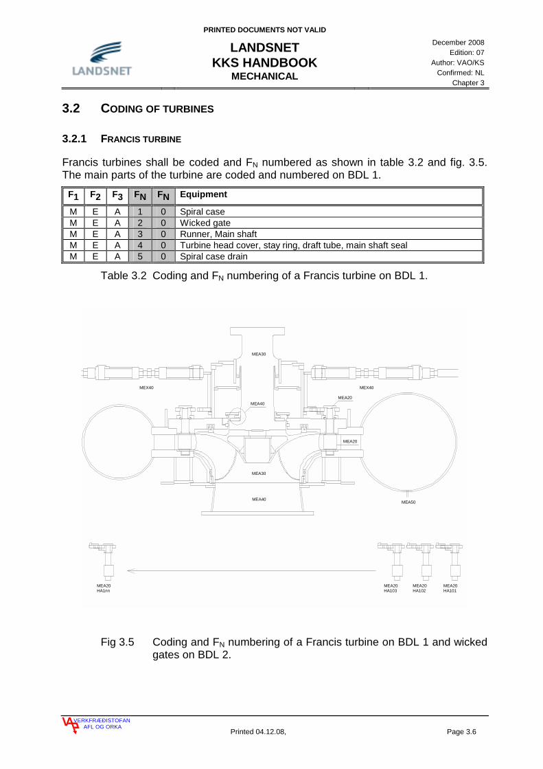
3.2 CODING OF TURBINES
3.2.1 FRANCIS TURBINE
Francis turbines shall be coded and FN numbered as shown in table 3.2 and fig. 3.5. The main parts of the turbine are coded and numbered on BDL 1.
F1 F2 F3 FN FN Equipment
M E A 1 0 Spiral case M E A 2 0 Wicked gate M E A 3 0 Runner, Main shaft M E A 4 0 Turbine head cover, stay ring, draft tube, main shaft seal M E A 5 0 Spiral case drain
Table 3.2 Coding and FN numbering of a Francis turbine on BDL 1.
HA1nnMEA20 MEA20
HA101MEA20HA103
MEA20HA102
MEA40
MEA30
MEA40
MEA30
MEX40 MEX40
MEA20
MEA20
MEA50
Fig 3.5 Coding and FN numbering of a Francis turbine on BDL 1 and wicked gates on BDL 2.
PRINTED DOCUMENTS NOT VALID
LANDSNET KKS HANDBOOK
MECHANICAL
December 2008
Edition: 07 Author: VAO/KS
Confirmed: NL Chapter 3
VERKFRÆÐISTOFANAFL OG ORKA
Printed 04.12.08, Page 3.7
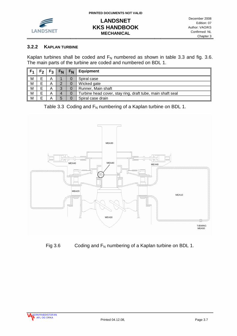
3.2.2 KAPLAN TURBINE
Kaplan turbines shall be coded and FN numbered as shown in table 3.3 and fig. 3.6. The main parts of the turbine are coded and numbered on BDL 1.
F1 F2 F3 FN FN Equipment
M E A 1 0 Spiral case M E A 2 0 Wicked gate M E A 3 0 Runner, Main shaft M E A 4 0 Turbine head cover, stay ring, draft tube, main shaft seal M E A 5 0 Spiral case drain
Table 3.3 Coding and FN numbering of a Kaplan turbine on BDL 1.
MEA30
MEA10
MEA30
MEA20
MEX40 MEA40 MEX40
TÆMINGMEA50
Fig 3.6 Coding and FN numbering of a Kaplan turbine on BDL 1.

PRINTED DOCUMENTS NOT VALID
LANDSNET KKS HANDBOOK
MECHANICAL
December 2008
Edition: 07 Author: VAO/KS
Confirmed: NL Chapter 3
VERKFRÆÐISTOFANAFL OG ORKA
Printed 04.12.08, Page 3.8
MEA20HA101
HB104MEA30
MEA20HA102
HA103MEA20
HA104MEA20
HA107MEA20
HA119MEA20
HA120MEA20
MEA20HA124
MEA30HB105 HB101
MEA30
HB103MEA30
HB102MEA30
Fig. 3.7 Coding of guide vanes and wicked gates of a Kaplan turbine on BDL 2.

PRINTED DOCUMENTS NOT VALID
LANDSNET KKS HANDBOOK
MECHANICAL
December 2008
Edition: 07 Author: VAO/KS
Confirmed: NL Chapter 3
VERKFRÆÐISTOFANAFL OG ORKA
Printed 04.12.08, Page 3.9
3.2.3 PELTON TURBINE
Pelton turbines shall be coded and FN numbered as shown below. The main parts of the turbine are coded and numbered on BDL 1.
F1 F2 F3 FN FN Equipment
M E A 1 0 Spiral case M E A 2 0 Wicked gate M E A 3 0 Runner, Main shaft M E A 4 0 Turbine head cover, stay ring, draft tube, main shaft seal M E A 5 0 Spiral case drain
Table 3.4 Coding and FN numbering of a Pelton turbine on BDL 1.
MEA10
MEA30
MEA10 LPC10
MEA20
Fig 3.8 Coding and FN numbering of a Pelton turbine on BDL 1.

PRINTED DOCUMENTS NOT VALID
LANDSNET KKS HANDBOOK
MECHANICAL
December 2008
Edition: 07 Author: VAO/KS
Confirmed: NL Chapter 3
VERKFRÆÐISTOFANAFL OG ORKA
Printed 04.12.08, Page 3.10
3.2.4 CODING OF STEAM TURBINES
Steam turbines shall be coded and FN numbered as shown below. The main parts of the turbine are coded and numbered on BDL 1.
F1 F2 F3 FN FN Equipment
M A A 1 0 Steam admission HP from main stop -/control valve M A A 2 0 Steam admission LP from main stop -/control valve M A A 3 - Steam blades M A A 3 1 Steam blades regulator side (if apropos) M A A 3 2 Steam blades generator side M A A 4 0 Turbine rotor M A A 5 0 Turbine casing, sealing and safety valves
Table 3.5 Coding and FN numbering of a steam turbine on BDL 1.
Steam shovels shall be coded on BDL 2. Steam shovels are divided into upper and lower shovels steps. Decadic numbering shall be used for the identification on upper and lower shovels in each pressure step and consecutive numbering is used for counting pressure steps.
A1 A2 AN AN AN A3 Equipment
H A - 1 - - Lower steam blades H A - 2 - - Upper steam blades H A - 1 1 - Lower steam blades, pressure step 1 H A - 1 2 - Lower steam blades, pressure step 2 H A - 1 3 - Lower steam blades, pressure step 3 H A - 1 n - Lower steam blades, pressure step n H A - 2 1 - Upper steam blades, pressure step 1 H A - 2 2 - Upper steam blades, pressure step 2 H A - 2 3 - Upper steam blades, pressure step 3 H A - 2 n - Upper steam blades, pressure step n
Table 3.6 Coding and AN numbering of steam blades on BDL 2.

PRINTED DOCUMENTS NOT VALID
LANDSNET KKS HANDBOOK
MECHANICAL
December 2008
Edition: 07 Author: VAO/KS
Confirmed: NL Chapter 3
VERKFRÆÐISTOFANAFL OG ORKA
Printed 04.12.08, Page 3.11
MAA
50
MAA
40
MAA
31H
A025 M
A A31
HA 0
24 MA
A31
HA0
23
MAA
31H
A022
MAA
31H
A021
MAA
32H
A015
MA
A32
HA0
14M
AA32
HA0
13M
AA32
HA
012
MAA
32H
A011
MAA
5 0
Fig 3.9 Coding and AN numbering of a steam turbine on BDL 1 and BDL 2.

PRINTED DOCUMENTS NOT VALID
LANDSNET KKS HANDBOOK
MECHANICAL
December 2008
Edition: 07 Author: VAO/KS
Confirmed: NL Chapter 3
VERKFRÆÐISTOFANAFL OG ORKA
Printed 04.12.08, Page 3.12
3.2.5 GOVERNOR OF A HYDRO TURBINE
Governors shall be coded on BDL 1 as shown. Consecutive numbering shall be used for subdividing each device.
F1 F2 F3 FN FN Equipment
M E X 1 0 Governor sump tank, pumps and pressure tank M E X 2 0 Governor actuator, main control system M E X 3 0 Governor, pilot control system M E X 4 0 Governor servomotors M E X 5 0 Governor air pressure device
Table 3.7 Coding of a governor for a hydro turbine on BDL 1.
M
ME
X10
CT0
01
CL0
02M
EX
10
ME
X10
CL0
02
ME
X20
CP
002
ME
X20
CP
003
ME
X20
CP
001
MEX
10C
L002
ME
X20
CL0
01
ME
X20
CL0
02
ME
X20
CL0
03
AT0
10M
EX
10
AP
010
ME
X11
AA
040
ME
X11
AT0
10M
EX11
AA
010
ME
X11
ME
X11
AA
020
AA
030
ME
X11
AA
011
ME
X11A
A06
0M
E X11
AP
010
ME
X12AA
011
MEX
12AA
060
ME
X12
AA
040
ME
X12
AA01
0M
EX1
2
AA
030
ME
X12
AA
020
ME
X12
ME
X20
AA
303
AA
302
ME
X20
ME
X20
AA
301
AA
010
ME
X12
AA
021
ME
X10
AA
040
ME
X25
AA
030
ME
X25
AA
201
ME
X25
AA
020
ME
X25
ME
X25
AA
010
AT0
10M
EX2
5
AA
011
ME
X25
ÞR
ÝS
TI-
LOFT
AA
0 10
ME
X21
ME
X22
AA
0 10
AA
010
ME
X23
ME
X23
AT0
10
AA
011
MEX
11
ME
X10
BB
010
ME
X10
AA
010
ME
X10
AA
020
ME
X10
AC
010
ME
X20
AA
010
ME
X10
AA
030
AA
040
MEX
20
AA
040
ME
X10
AA
020
MEX
23
AA
020
ME
X20
AA 3
0M
EX
31
ME
X31
AA02
0M
EX
31A
A01
0
AS
020
ME
X30
AS
010
ME
X30
ME
X40
AA
010
AT01
0M
EX
40
ME
X41
AA0
10
AA
011
ME
X42
AA
0 12
ME
X42
ME
X42
AA
013
AA01
0M
EX
42
AA
020
ME
X42
AA
0 20
ME
X41
ME
X41
AA
030
AA
040
ME
X41
Fig. 3.10 Example of coding and FN numbering of a governor items and devices for hydro turbine on BDL 1.
PRINTED DOCUMENTS NOT VALID
LANDSNET KKS HANDBOOK
MECHANICAL
December 2008
Edition: 07 Author: VAO/KS
Confirmed: NL Chapter 3
VERKFRÆÐISTOFANAFL OG ORKA
Printed 04.12.08, Page 3.13
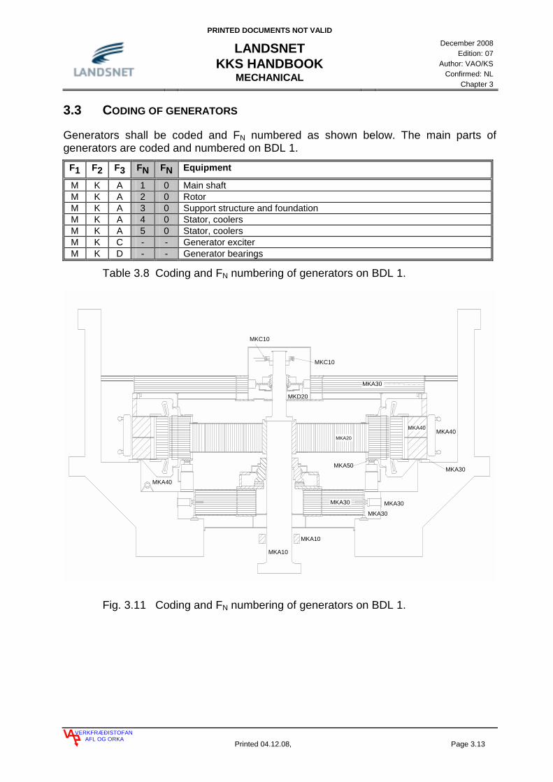
3.3 CODING OF GENERATORS
Generators shall be coded and FN numbered as shown below. The main parts of generators are coded and numbered on BDL 1.
F1 F2 F3 FN FN Equipment
M K A 1 0 Main shaft M K A 2 0 Rotor M K A 3 0 Support structure and foundation M K A 4 0 Stator, coolers M K A 5 0 Stator, coolers M K C - - Generator exciter M K D - - Generator bearings
Table 3.8 Coding and FN numbering of generators on BDL 1.
MKA30
MKA40
MKA20
MKA30
MKA40
MKA30
MKA30
MKA30
MKA50
MKC10
MKC10
MKA10
MKA10
MKA40
MKD20
Fig. 3.11 Coding and FN numbering of generators on BDL 1.

PRINTED DOCUMENTS NOT VALID
LANDSNET KKS HANDBOOK
MECHANICAL
December 2008
Edition: 07 Author: VAO/KS
Confirmed: NL Chapter 3
VERKFRÆÐISTOFANAFL OG ORKA
Printed 04.12.08, Page 3.14
3.4 CODING OF AIR-CONDITION SYSTEMS
Air condition system is coded as shown in table 3.9. The main parts of the system are identified on BDL 1 and numbering is done there.
F1 F2 F3 FN FN Equipment
S A A - - Stationary air condition system in substations S A C - - Stationary air condition in control houses S A L - - Stationary air condition system in intake constructions S A M - - Stationary air condition system in powerhouses S B A - - Stationary heating blowers in substations S B C - - Stationary heating blowers in control houses S B L - - Stationary heating blowers in intake constructions S B M - - Stationary heating blowers in powerhouses
Table 3.9 Coding of air-condition systems on BDL 1.
3.5 CODING OF GEOTHERMAL POWER PLANTS
Coding of Geothermal Power Plants is as shown in table 3.10. The main parts of the plant is grouped on BDL-1 where the numbering of the items is done.
F1 F2 F3 FN FN Equipment
L B A - - Steam production from well to and with out steam Separator L B B - - Steam supply from Separator to and without turbine main stop valve L B J - - Steam and moisture Seperators
Table 3.10 Coding of Geothermal Power Plants on BDL 1.
This is slightly different from the KKS key. This is necessary because the KKS key is designed for regular Thermal Power Plants but not Geothermal Power Plants. These definitions should only be used in Geothermal Power Plants. If coding a regular Steam Power Plant then the KKS key shall be used as it is from VGB.

PRINTED DOCUMENTS NOT VALID
LANDSNET KKS HANDBOOK
ELECTRICAL
April 2008 Edition: 06
Author: VAO/KS Confirmed: NL
Chapter 4
VERKFRÆÐISTOFANAFL OG ORKA
Printed 04.12.08 Page 4.1
4 IDENTIFICATION IN ELECTRICAL, CONTROL AND INSTRUMENTATION ENGINEERING 2
4.1 CODING OF POWER SYSTEMS 2 4.1.1 CODING OF LINE BAYS 3 4.2 CODING OF BUSBARS 8 4.3 CODING OF CIRCUIT BREAKERS, DISCONNECTORS AND EARTHING SWITCHES 10 4.3.1 EXAMPLES OF CODING OF CIRCUIT BREAKERS, DISCONNECTORS AND EARTHING
SWITCHES 11 4.3.2 SPECIAL CASES OF BREAKER CODING 18 4.4 CODING OF MAIN- AND DISTRIBUTION TRANSFORMERS INCLUDING EQUIPMENT CONNECTED TO TRANSFORMER 20 4.5 MEASURING CIRCUITS 22 4.5.1 CODING OF CURRENT- AND VOLTAGE CIRCUITS 22 4.6 KKS CODING EXAMPLES 26 4.7 CODING OF HIGH VOLTAGE MASTS 31 4.8 CODING FROM GENERATOR TO GENERATOR TRANSFORMER 32 4.8.1 CODING FROM NEUTRAL POINT OF GENERATOR TO GENERATOR TRANSFORMER 32 4.9 POWER TRANSMISSION AND AUXILIARY POWER SUPPLY IN POWER PLANTS 34 4.9.1 FURTHER DEFINITION OF DISTRIBUTION IN POWER PLANTS 34 4.10 EQUIPMENT AND POWER CIRCUIT CODING 39 4.11 DEFINITION BY LANDSNET ON FREE ALPHABETICAL CHARACTERS 40 4.11.1 DIRECT CURRENT SYSTEMS 40 4.11.2 CABLES, CONDUCTORS, INTERCONNECTING BOXES, BUSBARS AND HV FEED THROUGH 41 4.12 CODING FIBER OPTIC CABLE AND OPTICAL SYSTEM 42 4.13 RELAY PROTECTION 43 4.13.1 DISTRIBUTION 43 4.13.2 TRANSMISSION 46 4.13.3 PRODUCTION 49

PRINTED DOCUMENTS NOT VALID
LANDSNET KKS HANDBOOK
ELECTRICAL
April 2008 Edition: 06
Author: VAO/KS Confirmed: NL
Chapter 4
VERKFRÆÐISTOFANAFL OG ORKA
Printed 04.12.08 Page 4.2
4 IDENTIFICATION IN ELECTRICAL, CONTROL AND INSTRUMENTATION ENGINEERING
The following definition for F1 on BDL 1, applies for coding of the electrical part of Power Plants and distribution systems:
F1 F2 F3 FN FN Equipment A - - - - Grid and distribution B - - - - Power production and, auxiliary power systems C - - - - Instrumentation and control equipment
Table 4.1 Coding of the electrical part of Power Plants and distribution systems, BDL 1.
4.1 CODING OF POWER SYSTEMS
Distribution systems inside of Power Plants shall be coded with B on F1. Distribution, which is not coded under auxiliary supply (for own purpose) shall be coded under A on F1 and shall be coded according to the voltage levels defined in the KKS key from VGB on BDL 1 on F2 see table 4.2.
F1 F2 F3 FN FN Voltage A D - - - 220 (245) kV A E - - - 110 (150) kV A F - - - 60 (72) kV A H - - - 30 (35) kV A J - - - 20 (25) kV A K - - - 10 (15) kV A L - - - 6 (5) kV A M - - - 1 (3) kV A N - - - <1 kV
Table 4.2 Coding of voltage levels in distribution systems on BDL 1.
The main grid shall be coded under A on F1 and the coding shall be done according to the voltage levels defined in the KKS-key from VGB, see table 4.2. Line bays and transformer bays in Power Plants and main Sub Stations shall be coded as shown in tables 4.3 to 4.7 and shall be coded with A on F1. Line bays in transformer stations and in switchyards in power stations shall be coded as the switchyard on BDL ÷1 and as the line on BDL 0. Line and line bays shall always be coded L on BDL 1 on F3. F0 is 0 for the line itself, 1 for the switchyard where it starts in but 2 where it ends. Busbar connection have always T on BDL1 on F0 and F1 and it is counted on F2. Example: Búrfellslína 1 is connected from Búrfell to Írafoss. The line shall be coded BU1 BU1 0ADL, the line bay in Búrfell shall be coded BUR BU1 1ADL and the line bay in Írafoss shall be coded IRA BU1 2ADL.

PRINTED DOCUMENTS NOT VALID
LANDSNET KKS HANDBOOK
ELECTRICAL
April 2008 Edition: 06
Author: VAO/KS Confirmed: NL
Chapter 4
VERKFRÆÐISTOFANAFL OG ORKA
Printed 04.12.08 Page 4.3
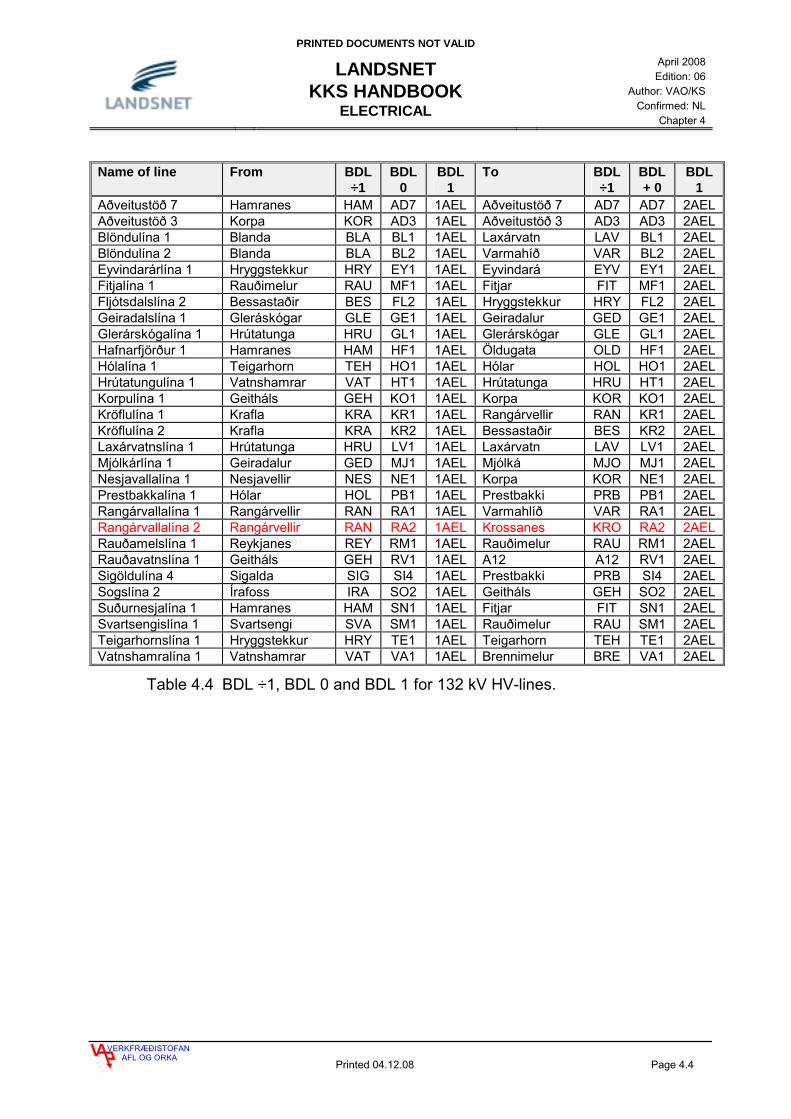
4.1.1 CODING OF LINE BAYS
Name of line From BDL
÷1 BDL
0 BDL
1 To BDL
÷1 BDL
0 BDL
1 Brennimelslína 1 Geitháls GEH BR1 1ADL Brennimelur BRE BR1 2ADLBúrfellslína 1 Búrfell BUR BU1 1ADL Írafoss IRA BU1 2ADLBúrfellslína 2 Búrfell BUR BU2 1ADL Kolviðarhóll KOL BU2 2ADLBúrfellslína 3 Búrfell BUR BU3 1ADL Hamranes HAM BU3 2ADLFljótsdalslína 3 Fljótsdalur FLJ FL3 1ADL Álv. Reyðarfirði ARE FL3 2ADLFljótsdalslína 4 Fljótsdalur FLJ FL4 1ADL Álv. Reyðarfirði ARE FL4 2ADLHamraneslína 1 Geitháls GEH HN1 1ADL Hamranes HAM HN1 2ADLHamraneslína 2 Geitháls GEH HN2 1ADL Hamranes HAM HN2 2ADLHrauneyjafosslína 1 Hrauneyjafoss HRA HR1 1ADL Sultartangi SUL HR1 2ADLÍsallína 1 Hamranes HAM IS1 1ADL Álv. Straumsvík AST IS1 2ADLÍsallína 2 Hamranes HAM IS2 1ADL Álv. Straumsvík AST IS2 2ADLJárnblendilína 1 Brennimelur BRE JA1 1ADL Járnblendi JAR JA1 2ADLKolviðarhólslína 1 Kolviðarhóll KOL KH1 1ADL Geitháls GEH KH1 2ADLNorðurálslína 1 Brennimelur BRE NA1 1ADL Álv. Hvalfirði AHV NA1 2ADLNorðurálslína 2 Brennimelur BRE NA2 1ADL Álv. Hvalfirði AHV NA2 2ADLSigöldulína 2 Sigalda SIG SI2 1ADL Hrauneyjafoss HRA SI2 2ADLSigöldulína 3 Sigalda SIG SI3 1ADL Búrfell BUR SI3 2ADLSogslína 3 Írafoss IRA SO3 1ADL Geitháls GEH SO3 2ADLSultartangalína 1 Sultartangi SUL SU1 1ADL Brennimelur BRE SU1 2ADLSultartangalína 2 Sultartangi SUL SU2 1ADL Búrfell BUR SU2 2ADLSultartangalína 3 Sultartangi SUL SU3 1ADL Brennimelur BRE SU3 2ADLVatnsfellslína 1 Vatnsfell VAF VF1 1ADL Sigalda SIG VF1 2ADL
Table 4.3 BDL ÷1, BDL 0 and BDL 1 for 220 kV HV-lines.
PRINTED DOCUMENTS NOT VALID
LANDSNET KKS HANDBOOK
ELECTRICAL
April 2008 Edition: 06
Author: VAO/KS Confirmed: NL
Chapter 4
VERKFRÆÐISTOFANAFL OG ORKA
Printed 04.12.08 Page 4.4
Name of line From BDL
÷1 BDL
0 BDL
1 To BDL
÷1 BDL + 0
BDL 1
Aðveitustöð 7 Hamranes HAM AD7 1AEL Aðveitustöð 7 AD7 AD7 2AEL Aðveitustöð 3 Korpa KOR AD3 1AEL Aðveitustöð 3 AD3 AD3 2AEL Blöndulína 1 Blanda BLA BL1 1AEL Laxárvatn LAV BL1 2AEL Blöndulína 2 Blanda BLA BL2 1AEL Varmahíð VAR BL2 2AEL Eyvindarárlína 1 Hryggstekkur HRY EY1 1AEL Eyvindará EYV EY1 2AEL Fitjalína 1 Rauðimelur RAU MF1 1AEL Fitjar FIT MF1 2AEL Fljótsdalslína 2 Bessastaðir BES FL2 1AEL Hryggstekkur HRY FL2 2AEL Geiradalslína 1 Gleráskógar GLE GE1 1AEL Geiradalur GED GE1 2AEL Glerárskógalína 1 Hrútatunga HRU GL1 1AEL Glerárskógar GLE GL1 2AEL Hafnarfjörður 1 Hamranes HAM HF1 1AEL Öldugata OLD HF1 2AEL Hólalína 1 Teigarhorn TEH HO1 1AEL Hólar HOL HO1 2AEL Hrútatungulína 1 Vatnshamrar VAT HT1 1AEL Hrútatunga HRU HT1 2AEL Korpulína 1 Geitháls GEH KO1 1AEL Korpa KOR KO1 2AEL Kröflulína 1 Krafla KRA KR1 1AEL Rangárvellir RAN KR1 2AEL Kröflulína 2 Krafla KRA KR2 1AEL Bessastaðir BES KR2 2AEL Laxárvatnslína 1 Hrútatunga HRU LV1 1AEL Laxárvatn LAV LV1 2AEL Mjólkárlína 1 Geiradalur GED MJ1 1AEL Mjólká MJO MJ1 2AEL Nesjavallalína 1 Nesjavellir NES NE1 1AEL Korpa KOR NE1 2AEL Prestbakkalína 1 Hólar HOL PB1 1AEL Prestbakki PRB PB1 2AEL Rangárvallalína 1 Rangárvellir RAN RA1 1AEL Varmahlíð VAR RA1 2AEL Rangárvallalína 2 Rangárvellir RAN RA2 1AEL Krossanes KRO RA2 2AEL Rauðamelslína 1 Reykjanes REY RM1 1AEL Rauðimelur RAU RM1 2AEL Rauðavatnslína 1 Geitháls GEH RV1 1AEL A12 A12 RV1 2AEL Sigöldulína 4 Sigalda SIG SI4 1AEL Prestbakki PRB SI4 2AEL Sogslína 2 Írafoss IRA SO2 1AEL Geitháls GEH SO2 2AEL Suðurnesjalína 1 Hamranes HAM SN1 1AEL Fitjar FIT SN1 2AEL Svartsengislína 1 Svartsengi SVA SM1 1AEL Rauðimelur RAU SM1 2AEL Teigarhornslína 1 Hryggstekkur HRY TE1 1AEL Teigarhorn TEH TE1 2AEL Vatnshamralína 1 Vatnshamrar VAT VA1 1AEL Brennimelur BRE VA1 2AEL
Table 4.4 BDL ÷1, BDL 0 and BDL 1 for 132 kV HV-lines.
PRINTED DOCUMENTS NOT VALID
LANDSNET KKS HANDBOOK
ELECTRICAL
April 2008 Edition: 06
Author: VAO/KS Confirmed: NL
Chapter 4
VERKFRÆÐISTOFANAFL OG ORKA
Printed 04.12.08 Page 4.5
Name From BDL
÷1 BDL
0 BDL 1 To BDL
÷1 BDL 0
BDL 1
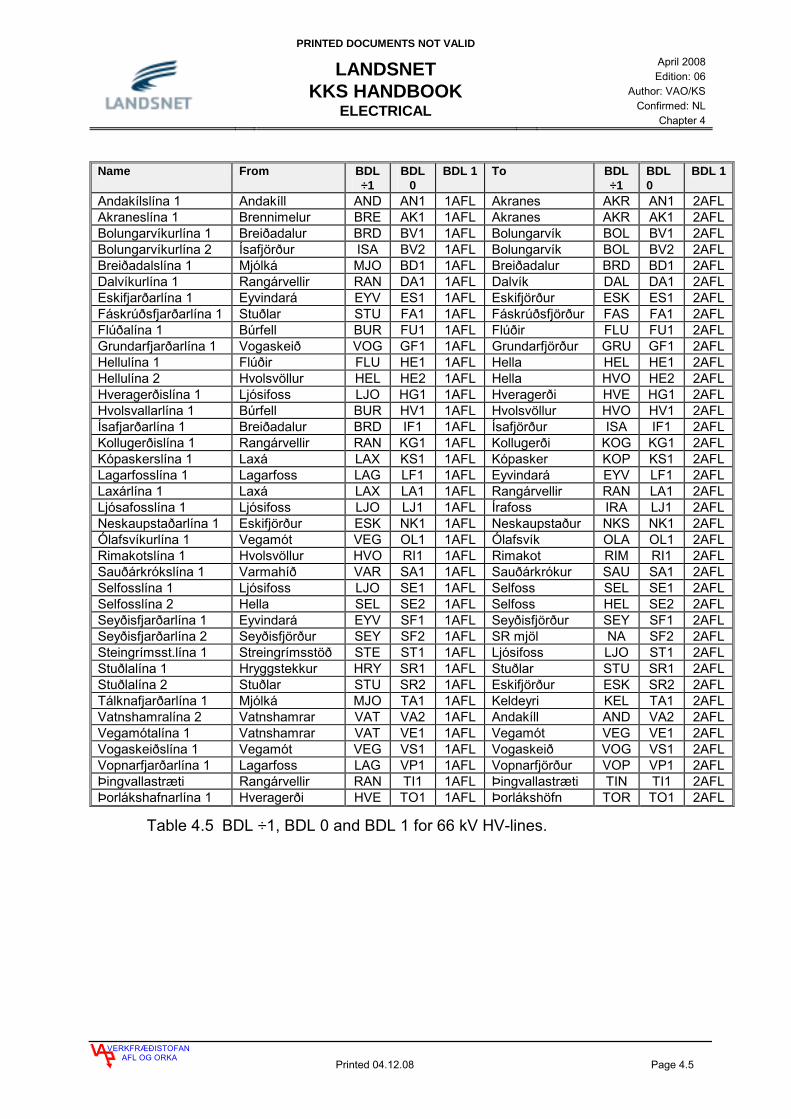
Andakílslína 1 Andakíll AND AN1 1AFL Akranes AKR AN1 2AFL Akraneslína 1 Brennimelur BRE AK1 1AFL Akranes AKR AK1 2AFL Bolungarvíkurlína 1 Breiðadalur BRD BV1 1AFL Bolungarvík BOL BV1 2AFL Bolungarvíkurlína 2 Ísafjörður ISA BV2 1AFL Bolungarvík BOL BV2 2AFL Breiðadalslína 1 Mjólká MJO BD1 1AFL Breiðadalur BRD BD1 2AFL Dalvíkurlína 1 Rangárvellir RAN DA1 1AFL Dalvík DAL DA1 2AFL Eskifjarðarlína 1 Eyvindará EYV ES1 1AFL Eskifjörður ESK ES1 2AFL Fáskrúðsfjarðarlína 1 Stuðlar STU FA1 1AFL Fáskrúðsfjörður FAS FA1 2AFL Flúðalína 1 Búrfell BUR FU1 1AFL Flúðir FLU FU1 2AFL Grundarfjarðarlína 1 Vogaskeið VOG GF1 1AFL Grundarfjörður GRU GF1 2AFL Hellulína 1 Flúðir FLU HE1 1AFL Hella HEL HE1 2AFL Hellulína 2 Hvolsvöllur HEL HE2 1AFL Hella HVO HE2 2AFL Hveragerðislína 1 Ljósifoss LJO HG1 1AFL Hveragerði HVE HG1 2AFL Hvolsvallarlína 1 Búrfell BUR HV1 1AFL Hvolsvöllur HVO HV1 2AFL Ísafjarðarlína 1 Breiðadalur BRD IF1 1AFL Ísafjörður ISA IF1 2AFL Kollugerðislína 1 Rangárvellir RAN KG1 1AFL Kollugerði KOG KG1 2AFL Kópaskerslína 1 Laxá LAX KS1 1AFL Kópasker KOP KS1 2AFL Lagarfosslína 1 Lagarfoss LAG LF1 1AFL Eyvindará EYV LF1 2AFL Laxárlína 1 Laxá LAX LA1 1AFL Rangárvellir RAN LA1 2AFL Ljósafosslína 1 Ljósifoss LJO LJ1 1AFL Írafoss IRA LJ1 2AFL Neskaupstaðarlína 1 Eskifjörður ESK NK1 1AFL Neskaupstaður NKS NK1 2AFL Ólafsvíkurlína 1 Vegamót VEG OL1 1AFL Ólafsvík OLA OL1 2AFL Rimakotslína 1 Hvolsvöllur HVO RI1 1AFL Rimakot RIM RI1 2AFL Sauðárkrókslína 1 Varmahíð VAR SA1 1AFL Sauðárkrókur SAU SA1 2AFL Selfosslína 1 Ljósifoss LJO SE1 1AFL Selfoss SEL SE1 2AFL Selfosslína 2 Hella SEL SE2 1AFL Selfoss HEL SE2 2AFL Seyðisfjarðarlína 1 Eyvindará EYV SF1 1AFL Seyðisfjörður SEY SF1 2AFL Seyðisfjarðarlína 2 Seyðisfjörður SEY SF2 1AFL SR mjöl NA SF2 2AFL Steingrímsst.lína 1 Streingrímsstöð STE ST1 1AFL Ljósifoss LJO ST1 2AFL Stuðlalína 1 Hryggstekkur HRY SR1 1AFL Stuðlar STU SR1 2AFL Stuðlalína 2 Stuðlar STU SR2 1AFL Eskifjörður ESK SR2 2AFL Tálknafjarðarlína 1 Mjólká MJO TA1 1AFL Keldeyri KEL TA1 2AFL Vatnshamralína 2 Vatnshamrar VAT VA2 1AFL Andakíll AND VA2 2AFL Vegamótalína 1 Vatnshamrar VAT VE1 1AFL Vegamót VEG VE1 2AFL Vogaskeiðslína 1 Vegamót VEG VS1 1AFL Vogaskeið VOG VS1 2AFL Vopnarfjarðarlína 1 Lagarfoss LAG VP1 1AFL Vopnarfjörður VOP VP1 2AFL Þingvallastræti Rangárvellir RAN TI1 1AFL Þingvallastræti TIN TI1 2AFL Þorlákshafnarlína 1 Hveragerði HVE TO1 1AFL Þorlákshöfn TOR TO1 2AFL
Table 4.5 BDL ÷1, BDL 0 and BDL 1 for 66 kV HV-lines.

PRINTED DOCUMENTS NOT VALID
LANDSNET KKS HANDBOOK
ELECTRICAL
April 2008 Edition: 06
Author: VAO/KS Confirmed: NL
Chapter 4
VERKFRÆÐISTOFANAFL OG ORKA
Printed 04.12.08 Page 4.6
Name From BDL
÷1 BDL 0
BDL 1
To BDL ÷1
BDL 0
BDL 1
Húsavíkurlína 1 Laxá LAX HU1 1AHL Húsavík HUS HU1 2AHL Hvammslína 1 Bessastaðir BES PS1 1AHL Hvammur HVA PS1 2AHL Kárahnjúkalína 1 Bessastaðir BES KA1 1AHL Teigsbjarg TEI KA1 2AHL Kárahnjúkalína 2 Teigsbjarg TEI KA2 1AHL Axará AXA KA2 2AHL Kárahnjúkalína 3 Axará AXA KA3 1AHL Tunga TGA KA3 2AHL Kárahnjúkalína 4 Tunga TGA KA4 1AHL Desjará DES KA4 2AHL Vestm.eyjalína 1 Rimakot RIM VM1 1AHL Vestm.eyjar VEM VM1 2AHLVestm.eyjalína 3 Rimakot * RIM VM2 1AHL Vestm.eyjar VEM VM2 2AHL
* 66 kV cable, operated on 33 kV
Table 4.6 BDL ÷1, BDL 0 and BDL 1 for 33 kV HV-lines.
Name From BDL ÷1
BDL 0
BDL 1
To BDL ÷1
BDL 0
BDL 1
Hafnarfjörður 2 Hamranes HAM HF2 1AKL Öldugata OLD HF2 2AKL Hafnarfjörður 3 Hamranes HAM HF3 1AKL Öldugata OLD HF3 2AKL Kárahnjúkalína 5 Tunga TGA KA5 1AKL Laugarás, KAR LAU KA5 2AKL Kárahnjúkalína 6 Laugarás LAU KA6 1AKL Skógarháls SKO KA6 2AKL Reykjarhlíðarlína Krafla KRA RE1 1AKL Reykjahlíð REK RE1 2AKL Ufsárlónslína 1 Axará AXA UF1 1AKL Ufsárlón, KAR UFS UF1 2AKL
Table 4.7 BDL ÷1, BDL 0 and BDL 1 for 11 kV HV-lines.

PRINTED DOCUMENTS NOT VALID
LANDSNET KKS HANDBOOK
ELECTRICAL
April 2008 Edition: 06
Author: VAO/KS Confirmed: NL
Chapter 4
VERKFRÆÐISTOFANAFL OG ORKA
Printed 04.12.08 Page 4.7
Name From BDL
÷1 BDL
0 BDL 1 To BDL
÷1 BDL 0
BDL 1
Bitrulína 1 Bitra BIT BI1 1ADL Hellisheiði HEH BI1 2ADL Bitrulína 2 Bitra BIT BI2 1ADL Hellisheiði HEH BI2 2ADL Bitrulína 3 Bitra BIT BI3 1ADL Hellisheiði HEH BI3 2ADL Bjarnarflagslína 1 Bjarnarflag BJA BJ1 1AEL Krafla KRA BJ1 2AEL Blöndulína 3 Blanda BLA BL3 1AEL Rangárvellir RAN BL3 2AEL Búðarhálslína 1 Búðarháls BUD BH1 1ADL Sultartangi SUL BH1 2ADL Fitjalína 1 Njarðvíkurheiði NJA FI1 1AEL Fitjar FIT FI1 2AEL Fitjalína 2 Njarðvíkurheiði NJA FI2 1AEL Fitjar FIT FI2 2AEL Fitjalína 3 Fitjar FIT FI3 1AEL Vallarheiði VAL FI3 2AEL Fitjalína 4 Fitjar FIT FI4 1AEL Vallarheiði VAL FI4 2AEL Helguvíkurlína 1 Njarðvíkurheiði NJA HL1 1ADL Álver Helguvík AHE HL1 2ADL Helguvíkurlína 2 Njarðvíkurheiði NJA HL2 1ADL Álver Helguvík AHE HL2 2ADL Hellisheiðarlína 1 Hellisheiði HEH HI1 1ADL Kolviðarhóll KOL HI1 2ADL Hellisheiðarlína 2 Hellisheiði HEH HI2 1ADL Kolviðarhóll KOL HI2 2ADL Hverahlíðalína 1 Hverahlíð HVH HH1 1ADL Hellisheiði HEH HH1 2ADL Hverahlíðalína 2 Hverahlíð HVH HH2 1ADL Hellisheiði HEH HH2 2ADL Hólasandslína 1 Hólasandur HSA HS1 1ADL Álver á Bakka ABA HS1 2ADL Hólasandslína 2 Hólasandur HSA HS2 1ADL Þeistareykir TRE HS2 2ADL Kolviðarhólslína 2 Kolviðarhóll KOL KH2 1ADL Njarðvíkurheiði NJA KH2 2ADL Kröflulína 3 Krafla KRA KR3 1ADL Fljótsdalur FLJ KR3 2ADL Kröflulína 4 Krafla KRA KR4 1ADL Hólasandur HSA KR4 2ADL Kröflulína 5 Krafla KRA KR5 1ADL Hólasandur HSA KR5 2ADL Nesjavallalína 2 Nesjavellir NES NE2 1AEL Geitháls GEH NE2 2AEL Rangárvallalína 3 Rangárvellir RAN RA3 1AEL Krossanes KRO RA3 2AEL Reykjaneslína 1 Njarðvíkurheiði NJA RN1 1ADL Reykjanes REY RN1 2ADL Reykjaneslína 2 Njarðvíkurheiði NJA RN2 1ADL Reykjanes REY RN2 2ADL Sandfellslína 1 Trölladyngja TRD SD1 1ADL Sandfell SAF SD1 2ADL Sandskeiðslína 1 Sandskeið SAN SS1 1ADL Hamranes HAM SS1 2ADL Sandskeiðslína 2 Sandskeið SAN SS2 1ADL Geitháls GEH SS2 2ADL Seltúnslína 1 Trölladyngja TRD SL1 1ADL Seltún SET SL1 2ADL Suðurnesjalína 2 Njarðvíkurheiði NJA SN2 1ADL Hamranes HAM SN2 2ADL Svartsengislína 1 Svartsengi SVA SV1 1AEL Fitjar FIT SV1 2AEL Trölladyngjulína 1 Trölladyngja TRD TD1 1ADL Kúagerði KUA TD1 2ADL Trölladyngjulína 2 Trölladyngja TRD TD2 1ADL Kúagerði KUA TD2 2ADL Vestm.eyjalína 3 Rimakot RIM VM3 1AFL Vestm.eyjar VEM VM3 2AFL Þeistareykjalína 1 Þeistareykir TRE TR1 1ADL Álver á Bakka ABA TR1 2ADL Þorlákshafnarlína 2 Kolviðarhóll KOL TO2 1ADL Þorlákshöfn TOR TO2 2ADL Þorlákshafnarlína 3 Hellisheiði HEH TO3 1ADL Þorlákshöfn TOR TO3 2ADL
Table 4.8 Expected BDL ÷1, BDL 0 and BDL 1 for new lines.

PRINTED DOCUMENTS NOT VALID
LANDSNET KKS HANDBOOK
ELECTRICAL
April 2008 Edition: 06
Author: VAO/KS Confirmed: NL
Chapter 4
VERKFRÆÐISTOFANAFL OG ORKA
Printed 04.12.08 Page 4.8
4.2 CODING OF BUSBARS
Busbars are coded according to the process code. They are coded with 0 on F0 on BDL 1 and under A or B on F1 on BDL 1. In group A, busbars that are connected to transmission lines and line bays which are outgoing lines from Power Plants and Sub Stations. Electrical distribution in group B, is distribution needed for the production, transmission and distribution of electrical energy. On F2 they shall be coded according to the voltage levels, defined in the KKS key, see table 4.2. On F3 they shall be coded A for A-busbar, B for B busbar or V for spare busbar. Numbering is on FN.
0ADA10
0ADB10
0AEA10
0AEB10
0AFA10
0AFB10
0AHA10
220kV
132 kV
66 kV
22 kV 0AJA10
19 kV 0AJB10
0ANB100.69 kV
0AKA10
33 kV
0ANA100.4 kV
11 kV
Fig. 4.1 Coding of busbars in distribution systems outside of Power Plants.
PRINTED DOCUMENTS NOT VALID
LANDSNET KKS HANDBOOK
ELECTRICAL
April 2008 Edition: 06
Author: VAO/KS Confirmed: NL
Chapter 4
VERKFRÆÐISTOFANAFL OG ORKA
Printed 04.12.08 Page 4.9
=BFA10
=BFB10 =BFC10
=BJA10 =BJB10 =BJC10
=BJA32
=BJA31=BJC22
=BJB20=BJA30=BJA20
=BJC21
=BJC20
MAIN DISTRIBUTION BOARDS
JUNCTION BOXES
SUB DISTRIUBUTION BOARDS
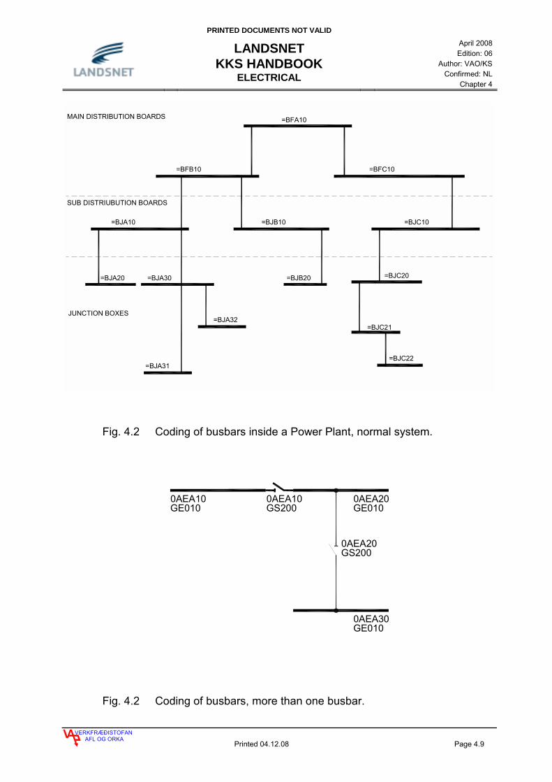
Fig. 4.2 Coding of busbars inside a Power Plant, normal system.
0AEA20
0AEA100AEA10GE010 GS200
0AEA20GE010
0AEA30GE010
GS200
Fig. 4.2 Coding of busbars, more than one busbar.

PRINTED DOCUMENTS NOT VALID
LANDSNET KKS HANDBOOK
ELECTRICAL
April 2008 Edition: 06
Author: VAO/KS Confirmed: NL
Chapter 4
VERKFRÆÐISTOFANAFL OG ORKA
Printed 04.12.08 Page 4.10
4.3 CODING OF CIRCUIT BREAKERS, DISCONNECTORS AND EARTHING SWITCHES
Circuit breakers disconnectors and earthing switches are coded as shown in table 4.9, they are separated on BDL 2 where numbering is made. Breakers are named GS_ _ _ and are counted in hundreds with the AN numbers in such a way that the circuit brakers are in the group 100, disconnectors are in group 200 and earthing switches are in group 300.
A1 A2 AN AN AN A3 Equipment
G S 1 0 0 - Circuit breakers G S 2 0 0 - Disconnector on busbar G S 2 1 0 - Disconnector on A busbar G S 2 2 0 - Disconnector on line and transformer G S 2 3 0 - Disconnector, bypass disconnector G S 2 4 0 - Disconnector, direct connecting of lines G S 2 5 0 - Disconnector on a spair busbar G S 2 7 0 - Disconnector on B busbar G S 2 9 0 - Disconnector on connection of A and B busbars G S 3 0 0 - Earthing switch on line, transformer and busbar G S 3 1 0 - Earthing switches on circuit braker G S 3 2 0 - Earthing switches on circuit braker G S 3 3 0 - Earthing switches on line, transformer
Table 4.9 Coding breakers on BDL 2.
For further information see fig. 4.3 to 4.9. In special cases table 4.11 does not apply, those cases are in table 4.10. Two special cases are in Hamranes og Hrauneyjafossstöð. In Hamranes on the 11kV there are two circuit breaker carriers for each circuit breaker, circuit breaker carrier one shall be coded GS100 but circuit breaker carrier two shall be coded GS105, see picture 4.10. In Hrauneyjafossstöð the line disconnector is coded GS200 because of special circumstances, see picture 4.11.
A1 A2 AN AN AN A3 Búnaður
G S 1 0 5 - For one of the two circuit breaker carrier that are equal, the other one shall be coded GS100
G S 2 0 0 - Disconnector on line in special circumstances as in HrauneyjafossstöðG S 2 1 5 - For one of the two disconnector carrier that are equal, the other one
shall be coded GS210
Table 4.10 Special cases for coding breakers on BDL 2.

PRINTED DOCUMENTS NOT VALID
LANDSNET KKS HANDBOOK
ELECTRICAL
April 2008 Edition: 06
Author: VAO/KS Confirmed: NL
Chapter 4
VERKFRÆÐISTOFANAFL OG ORKA
Printed 04.12.08 Page 4.11
4.3.1 EXAMPLES OF CODING OF CIRCUIT BREAKERS, DISCONNECTORS AND EARTHING SWITCHES
Fig. 4.3 Coding of circuit breakers, disconnectors and earthing switches on BDL 2, single busbar.
GS220
GS100
GS210 GS230
GS300
GS310
GS200
GS310
GS320
GS100
GS210
GS220
SINGLE BUSBARS
GS100
GS210
GS210
_ _ A 10
GS220
GS100
GS210 GS230
GS300 GS300
GS230
GS310
GS220
GS100
GS210 GS230
GS300
GS210
GS220
LINE/TRANSF. LINE/TRANSF.
LINE/TRANSF.
LINE/COND.CAP. NOT DRAWN
LINE LINE

PRINTED DOCUMENTS NOT VALID
LANDSNET KKS HANDBOOK
ELECTRICAL
April 2008 Edition: 06
Author: VAO/KS Confirmed: NL
Chapter 4
VERKFRÆÐISTOFANAFL OG ORKA
Printed 04.12.08 Page 4.12
Fig. 4.4 Coding of circuit breakers, disconnectors and earthing switches on BDL 2, single busbars.
UNIT
SINGLE BUSBARS
=_ _ A10 GS300
TRANSF.
GS210
GS100
GS100
GS210
GS100
GS210 GS210
GS300
GS220
GS210
GS100
GS300
GS100
GS220
GS210
LINE
GS200
LINE LINE LINE
_ _ A 10
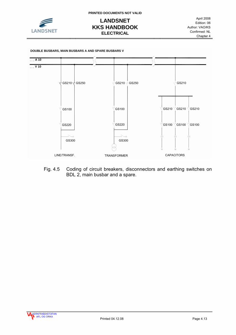
PRINTED DOCUMENTS NOT VALID
LANDSNET KKS HANDBOOK
ELECTRICAL
April 2008 Edition: 06
Author: VAO/KS Confirmed: NL
Chapter 4
VERKFRÆÐISTOFANAFL OG ORKA
Printed 04.12.08 Page 4.13
Fig. 4.5 Coding of circuit breakers, disconnectors and earthing switches on BDL 2, main busbar and a spare.
LINE/TRANSF. TRANSFORMER
DOUBLE BUSBARS, MAIN BUSBARS A AND SPARE BUSBARS V
GS210
GS100GS100
GS220 GS220
GS250
GS300
GS210 GS250
GS210
GS100
GS210
GS100
GS210
GS210
GS100
CAPACITORS
GS300
_ _ A 10
_ _ V 10

PRINTED DOCUMENTS NOT VALID
LANDSNET KKS HANDBOOK
ELECTRICAL
April 2008 Edition: 06
Author: VAO/KS Confirmed: NL
Chapter 4
VERKFRÆÐISTOFANAFL OG ORKA
Printed 04.12.08 Page 4.14
Fig. 4.6 Coding of circuit breakers, disconnectors and earthing switches on BDL 2, main busbar and a spare.
SPARE BUSBARS CONNECTORS
LINE/TRANSF.
DOUBLE BUSBARS, MAIN BUSBARS A AND SPARE BUSBARS V
GS210
GS100GS100
GS220
GS250 GS210 GS250
GS330
_ _ A 10
_ _ V 10
GS320
GS310

PRINTED DOCUMENTS NOT VALID
LANDSNET KKS HANDBOOK
ELECTRICAL
April 2008 Edition: 06
Author: VAO/KS Confirmed: NL
Chapter 4
VERKFRÆÐISTOFANAFL OG ORKA
Printed 04.12.08 Page 4.15
Fig. 4.7 Coding of circuit breakers, disconnectors and earthing switches on BDL 2, double busbar.
DOUBLE BUSBARS, MAIN BUSBARS A AND B
GS210 GS270
GS100
GS320
GS310
GS220
GS330
GS240LINE
_ _ A 10
_ _ B 10
GS210 GS270
GS100
GS320
GS310
GS220
GS330
LINE
GS210 GS270
GS100
GS320
GS310
GS220
GS330
TRANSFORMER

PRINTED DOCUMENTS NOT VALID
LANDSNET KKS HANDBOOK
ELECTRICAL
April 2008 Edition: 06
Author: VAO/KS Confirmed: NL
Chapter 4
VERKFRÆÐISTOFANAFL OG ORKA
Printed 04.12.08 Page 4.16
Fig. 4.8 Coding of circuit breakers, disconnectors and earthing switches on BDL 2, triple busbar, main busbar A and B and a spare.
TRIPLE BUSBARS, MAIN BUSBARS A AND B AND SPARE BUSBAR V
GS100
GS320
GS220
GS310
GS330
GS270 GS250 GS290
GS100 GS100
GS210
GS310
GS320
GS310
GS320
GS270GS210 GS210GS250 GS290
_ _ A 10
_ _ B 10
_ _ V 10
LINE
MAIN AND SPAREBUSBARS CONNECTOR
MAIN BUSBARS CONNECTOR

PRINTED DOCUMENTS NOT VALID
LANDSNET KKS HANDBOOK
ELECTRICAL
April 2008 Edition: 06
Author: VAO/KS Confirmed: NL
Chapter 4
VERKFRÆÐISTOFANAFL OG ORKA
Printed 04.12.08 Page 4.17
TRIPLE BUSBARS, MAIN BUSBARS A AND B AND SPARE BUSBARS V
ADA10 GS300
ADB10 GS300
ADV10 GS300
SPARE BUSBARSCONNECTORS
BÚRFELL(GIS)
GS100
GS320
GS310
GS210 GS270 GS250
BUSBARS EARTING SWITCHES
SULTARTANGI (GIS)
_ _ A 10
_ _ B 10
_ _ V 10
Fig. 4.9 Coding of circuit breakers, disconnectors and earthing switches on BDL 2, triple busbar, main busbar A and B and a spare.

PRINTED DOCUMENTS NOT VALID
LANDSNET KKS HANDBOOK
ELECTRICAL
April 2008 Edition: 06
Author: VAO/KS Confirmed: NL
Chapter 4
VERKFRÆÐISTOFANAFL OG ORKA
Printed 04.12.08 Page 4.18
4.3.2 SPECIAL CASES OF BREAKER CODING
0AKQ20GS300
GE0100AKV10
0AKA10GE010
0AKQ20
HAMHAM
HAMHAM
HAMQC2
GS1050AKQ20
HAMQC2
QC2HAM
GS1000AKQ20QC2HAM
HAMQC20AKQ20
HF2
HF2HAM
GS3001AKL10
HAMHF21AKL10
1AKL10
GS1051AKL10HF2HAM
HAM
HAMHF21AKL10GS100
CE100 CE100
Fig. 4.10 Special case, coding of circuit breaker carrier in Hamranes.

PRINTED DOCUMENTS NOT VALID
LANDSNET KKS HANDBOOK
ELECTRICAL
April 2008 Edition: 06
Author: VAO/KS Confirmed: NL
Chapter 4
VERKFRÆÐISTOFANAFL OG ORKA
Printed 04.12.08 Page 4.19
2ADL10SI2HRA
GS2200ADA40HRAHRA
HRA
SI2HRA
GS3102ADL10
0ADA40
HRA
HRASI22ADL10GS200
CE200
CE100
MM
HRASI2
GS3202ADL10
M
HRASI22ADL10
GV1002ADL10SI2HRA 2ADL10
SI2HRA
HRAM
GS3200ADA40HRA
GS100
HRA
0ADA40HRA
HRAHRA
GS3100ADA40
MGS210
HRA
0ADA40HRA
0ADA40
GS210
HRA0ADA30
HRA
M
HRA
GS320
HRA0ADA30 0ADA30
CE100
HRAHRA
GS1000ADA30HRAHRA
HRA
GS310
HRAM
0ADA30
GS2200ADA30HRAHRA
0ADA30
MM M M
Fig. 4.11 Special case, coding of disconnectors in Hrauneyjafossstöð.

PRINTED DOCUMENTS NOT VALID
LANDSNET KKS HANDBOOK
ELECTRICAL
April 2008 Edition: 06
Author: VAO/KS Confirmed: NL
Chapter 4
VERKFRÆÐISTOFANAFL OG ORKA
Printed 04.12.08 Page 4.20
4.4 CODING OF MAIN- AND DISTRIBUTION TRANSFORMERS INCLUDING EQUIPMENT CONNECTED TO TRANSFORMER
In F0 on BDL 1 the equipment gets the same numbering as in F0 for the transformer. When there are several transformers counting is done here. Circuit breakers and disconnectors as well as all equipment connected to transformers which are connected to busbars shall be coded in F1 on BDL 1 according to the busbars to which it is connected. F2 has a figure according to the voltage level on the equipment in question (see table 4.2). The transformer is coded by his highest voltage. F3 is T indicating transformer and transformer equipment. If the transformer is connected to a busbar for distribution inside a Power Plant, the equipment connected to that busbar is coded with the busbar but not with the transformer.
AFA10
1AFT10GS100
1AET10
GE010
1AET10CE100
1AET10GS100
AEA10GE 010
1AKT10GS100AKA10
GE010
11 kV
132 kV
66 kV
Fig. 4.12 Coding of circuit breakers, disconnectors for transformers and coding of busbars distribution outside of Power Plants.
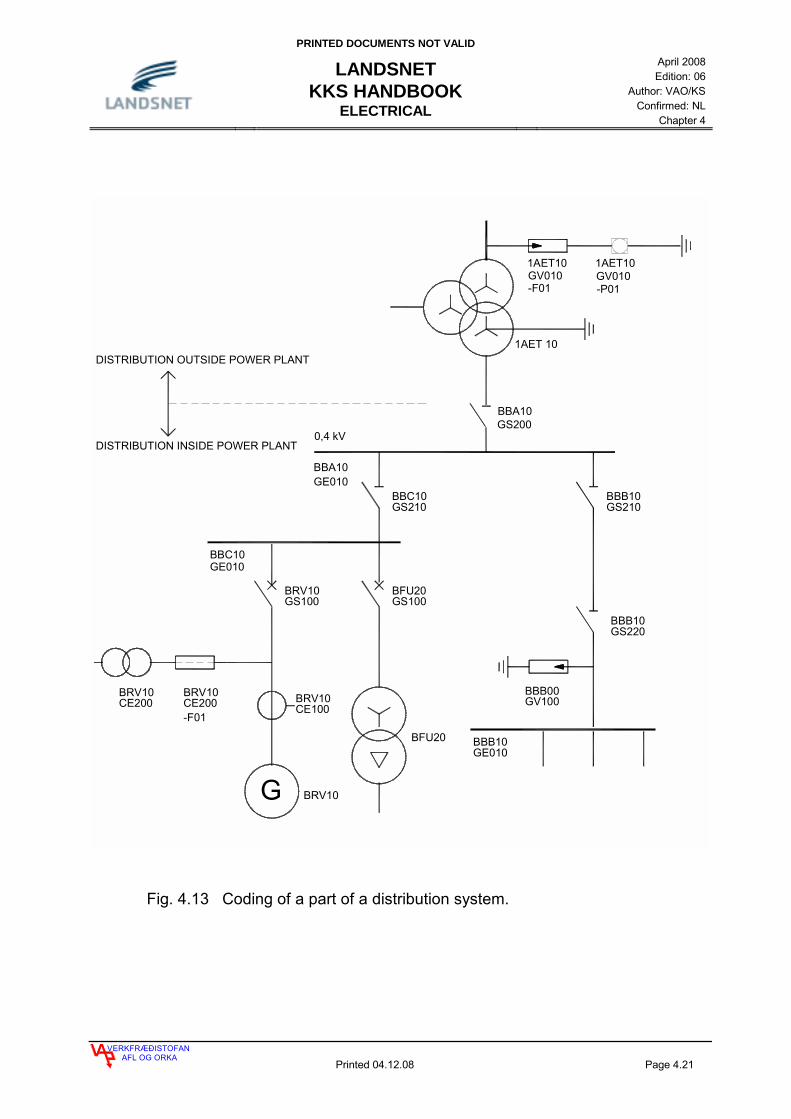
PRINTED DOCUMENTS NOT VALID
LANDSNET KKS HANDBOOK
ELECTRICAL
April 2008 Edition: 06
Author: VAO/KS Confirmed: NL
Chapter 4
VERKFRÆÐISTOFANAFL OG ORKA
Printed 04.12.08 Page 4.21
BBB00GV100
BBB10GS220
BFU20GS100
BFU20
BRV10CE200
BRV10GS100
G BRV10
BRV10CE100
BBC10GS210
BBB10GS210
BBA10
BBA10GS200
BBC10
1AET 10
GE010
GE010
BRV10CE200-F01
BBB10GE010
0,4 kV
DISTRIBUTION OUTSIDE POWER PLANT
DISTRIBUTION INSIDE POWER PLANT
1AET10GV010
1AET10GV010
-F01 -P01
Fig. 4.13 Coding of a part of a distribution system.
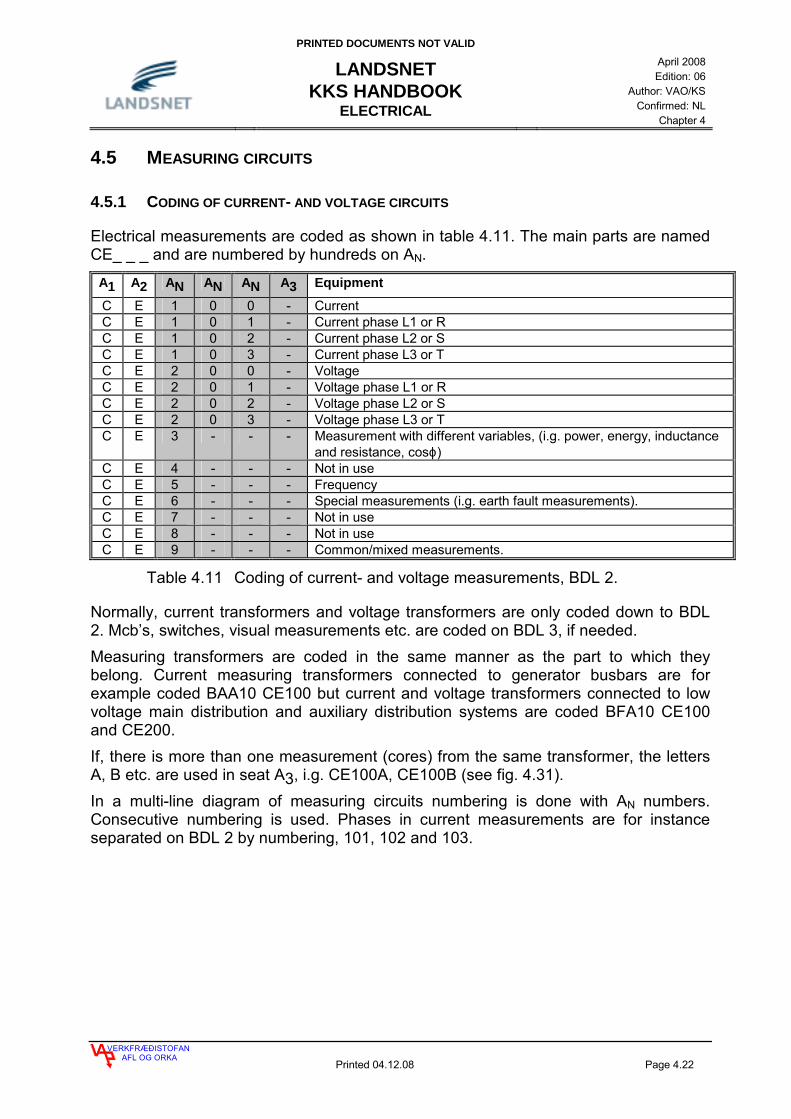
PRINTED DOCUMENTS NOT VALID
LANDSNET KKS HANDBOOK
ELECTRICAL
April 2008 Edition: 06
Author: VAO/KS Confirmed: NL
Chapter 4
VERKFRÆÐISTOFANAFL OG ORKA
Printed 04.12.08 Page 4.22
4.5 MEASURING CIRCUITS
4.5.1 CODING OF CURRENT- AND VOLTAGE CIRCUITS
Electrical measurements are coded as shown in table 4.11. The main parts are named CE_ _ _ and are numbered by hundreds on AN.
A1 A2 AN AN AN A3 Equipment
C E 1 0 0 - Current C E 1 0 1 - Current phase L1 or R C E 1 0 2 - Current phase L2 or S C E 1 0 3 - Current phase L3 or T C E 2 0 0 - Voltage C E 2 0 1 - Voltage phase L1 or R C E 2 0 2 - Voltage phase L2 or S C E 2 0 3 - Voltage phase L3 or T C E 3 - - - Measurement with different variables, (i.g. power, energy, inductance
and resistance, cosϕ) C E 4 - - - Not in use C E 5 - - - Frequency C E 6 - - - Special measurements (i.g. earth fault measurements). C E 7 - - - Not in use C E 8 - - - Not in use C E 9 - - - Common/mixed measurements.
Table 4.11 Coding of current- and voltage measurements, BDL 2.
Normally, current transformers and voltage transformers are only coded down to BDL 2. Mcb’s, switches, visual measurements etc. are coded on BDL 3, if needed. Measuring transformers are coded in the same manner as the part to which they belong. Current measuring transformers connected to generator busbars are for example coded BAA10 CE100 but current and voltage transformers connected to low voltage main distribution and auxiliary distribution systems are coded BFA10 CE100 and CE200. If, there is more than one measurement (cores) from the same transformer, the letters A, B etc. are used in seat A3, i.g. CE100A, CE100B (see fig. 4.31). In a multi-line diagram of measuring circuits numbering is done with AN numbers. Consecutive numbering is used. Phases in current measurements are for instance separated on BDL 2 by numbering, 101, 102 and 103.

PRINTED DOCUMENTS NOT VALID
LANDSNET KKS HANDBOOK
ELECTRICAL
April 2008 Edition: 06
Author: VAO/KS Confirmed: NL
Chapter 4
VERKFRÆÐISTOFANAFL OG ORKA
Printed 04.12.08 Page 4.23
BFT10CE200-F01
BFT10CE200
BFT10CE200-P01
BFT10
BFT10CE100
V
BFT10CE100-P01
A
Fig. 4.14 Coding of measuring transformers and meters.
BAA10CE100
BAA10CE101
BAA10CE102
BAA10CE103
SINGLELINE DIAGRAM MULTILINE DIAGRAM
Fig. 4.15 Coding of current transformers with one secondary winding.

PRINTED DOCUMENTS NOT VALID
LANDSNET KKS HANDBOOK
ELECTRICAL
April 2008 Edition: 06
Author: VAO/KS Confirmed: NL
Chapter 4
VERKFRÆÐISTOFANAFL OG ORKA
Printed 04.12.08 Page 4.24
3 BAA10
BAA10
3BAA10
BAA10
3
BAA10CE101A
BAA10CE102A
BAA10CE103A
BAA10CE101B
BAA10CE102B
BAA10CE103B BAA10
CE101BBAA10CE102B
BAA10CE103B
BAA10CE101A
BAA10CE102A
BAA10CE103A
CE100B
CE100A
CE100B
CE100A
a) 3x1 with 2 secondary b) 3x1 with 2 secondary windings on one core windings on different cores
Fig. 4.16 Coding of current transformers with two secondary windings.
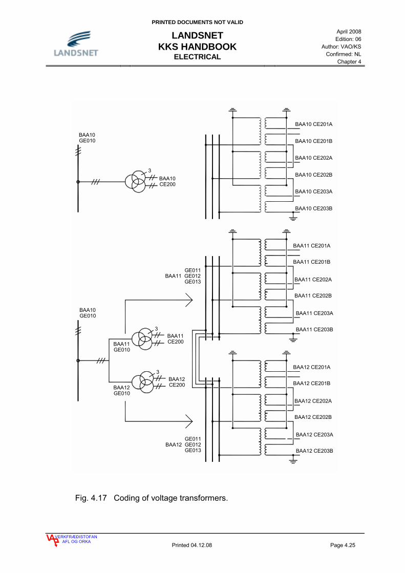
PRINTED DOCUMENTS NOT VALID
LANDSNET KKS HANDBOOK
ELECTRICAL
April 2008 Edition: 06
Author: VAO/KS Confirmed: NL
Chapter 4
VERKFRÆÐISTOFANAFL OG ORKA
Printed 04.12.08 Page 4.25
GE011BAA11 GE012
GE013
3BAA10CE200
BAA10GE010
BAA10 CE201A
BAA10 CE201B
BAA10 CE202A
BAA10 CE202B
BAA10 CE203A
BAA10 CE203B
BAA11 CE201A
BAA11 CE201B
BAA11 CE202A
BAA11 CE202B
BAA11 CE203A
BAA11 CE203B
BAA12 CE201A
BAA12 CE201B
BAA12 CE202A
BAA12 CE202B
BAA12 CE203A
BAA12 CE203B
3
BAA12CE200
BAA10GE010
3
BAA11CE200
BAA12GE010
BAA11GE010
GE011BAA12 GE012
GE013
Fig. 4.17 Coding of voltage transformers.
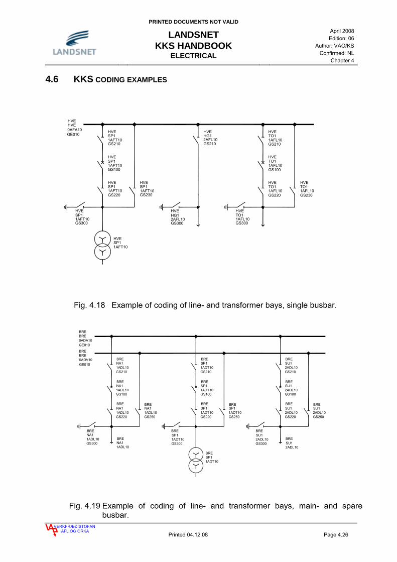
PRINTED DOCUMENTS NOT VALID
LANDSNET KKS HANDBOOK
ELECTRICAL
April 2008 Edition: 06
Author: VAO/KS Confirmed: NL
Chapter 4
VERKFRÆÐISTOFANAFL OG ORKA
Printed 04.12.08 Page 4.26
4.6 KKS CODING EXAMPLES
HG12AFL10GS210
HG12AFL10GS300
SP11AFT10GS210
SP11AFT10GS100
SP11AFT10GS220
SP11AFT10GS230
SP11AFT10GS300
TO11AFL10GS210
TO11AFL10GS100
TO11AFL10GS220
TO11AFL10GS230
TO11AFL10GS300
0AFA10
SP11AFT10
HVE
GE010
HVE
HVE
HVE
HVE
HVE
HVE HVEHVE HVE
HVE
HVE
HVE HVE
HVE
Fig. 4.18 Example of coding of line- and transformer bays, single busbar.
NA11ADL10GS210
NA11ADL10GS100
NA11ADL10GS220
NA11ADL10GS250
NA11ADL10GS300
SP11ADT10GS210
SP11ADT10GS100
SP11ADT10GS220
SP11ADT10GS250
SP11ADT10GS300
SU12ADL10GS210
SU12ADL10GS100
SU12ADL10GS220
SU12ADL10GS250
SU12ADL10GS300
SP11ADT10
BRE0ADA10GE010
BRE0ADV10GE010
BRE
BRE
BRE
BRE
BRE
BRE
BRE BREBRE
BRE
BRE
BRE
BRE
BRE
BRE
BRE
BRE
BRE
1ADL10
BRENA1
BRE
2ADL10SU1
Fig. 4.19 Example of coding of line- and transformer bays, main- and spare busbar.

PRINTED DOCUMENTS NOT VALID
LANDSNET KKS HANDBOOK
ELECTRICAL
April 2008 Edition: 06
Author: VAO/KS Confirmed: NL
Chapter 4
VERKFRÆÐISTOFANAFL OG ORKA
Printed 04.12.08 Page 4.27
1ADL10GS330
GE0100ADA10
0ADB10GE010
1ADT101ADL10
HAMHAM
HAMHAM
HAMHAM
0ADV10GE010
HAMIS1
IS1
GS3201ADL10
HAM
IS11ADL10GS310
HAM
HAM
GS2701ADL10IS1
1ADL10GS210
IS1HAM
1ADL10GS250
IS1HAM
GS1001ADL10
HAMIS1
1ADL10GS220
IS1HAM
SP1
GS3301ADL10
HAM
GS320
HAMSP11ADT10
HAM
GS3101ADT10SP1
GS220
GS100
1ADT10
1ADT10
HAMSP1
SP1HAM
GS2101ADT10
HAMSP1
1ADT10GS270
SP1HAM
1ADT10GS250
HAMSP1
HAM
0ADA10GS310
TT1
GS320
TT10ADA10
HAM
0ADA10GS100
TT1HAM
GS2100ADA10TT1HAM
1ADB10GS270
TT1HAM
0ADB10GS290
HAMTT1
0ADV10GS250
TT1HAM
IS1SP1HAM
HAM
Fig. 4.20 Example of coding line- and transformer bays, two busbars and one spare.

PRINTED DOCUMENTS NOT VALID
LANDSNET KKS HANDBOOK
ELECTRICAL
April 2008 Edition: 06
Author: VAO/KS Confirmed: NL
Chapter 4
VERKFRÆÐISTOFANAFL OG ORKA
Printed 04.12.08 Page 4.28
ADA10
BRENNIMELUR (BRE)
GG
G
GEN 2
GEN 3 AND 4
AEA10
2ADT10
ADV10
ADA10
HRAUNEYJAFOSS (HRA)
ADA10
SIGALDA (SIG)
AEA10
AEV10
ADV10
ADA10
GEITHÁLS (GEH)
BREBR12ADL10 1ADT10
SP1BRE
2ADL10HR1BRE
1ADL10HR1HRA
2ADL10SI2HRA
1ADL10SI2SIG
2ADL10SP2SIG
1ADL10SI3SIG
1ADT10SU10ADLnnn 0ADLnnn
SI2
BR10ADLnnn
SO3GEH
2ADL10
1ADT10
1ADT10SP1GEH
1ADL10BR1GEH
ÍRAFOSS (IRA) BÚRFELL (BUR)
1ADL10
IRASO3
2ADL10
IRABU1
1ADL10
BURBU1
2ADT10
BURSP2
2ADL10
BURSI3
0ADLnnnSI3
0ADLnnnBU1
0ADLnnnSO3
1AET10SP1GEH
1AET10SP1BRE 1ADL10
SULTARTANGI (SUL)
ADB10
ADV10
SULSU1
ADA10
SUL
2ADL10HR1
0ADLnnnHR1
ADA10 ADA10
Fig. 4.21 Example of coding in the 220 kV grid.

PRINTED DOCUMENTS NOT VALID
LANDSNET KKS HANDBOOK
ELECTRICAL
April 2008 Edition: 06
Author: VAO/KS Confirmed: NL
Chapter 4
VERKFRÆÐISTOFANAFL OG ORKA
Printed 04.12.08 Page 4.29
1AEL10EU010
1AEL10CE100
1AEL10EU010
1AEL10GS300
1AEL10GS210
1AEL10GS100
1AEL10GS220
1AEL10GS230
1AEL10GS230
1AEL10GS220
1AEL10GS100
1AEL10GS210
1AEL10CE200
1AEL10CE200
0AEA10GE010
1AEL10GS300
CE1001AEL10
Fig. 4.22 Example of single phase coding of a 132 kV bays separated on BDL 0.
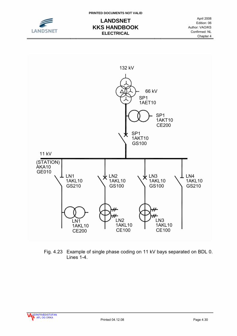
PRINTED DOCUMENTS NOT VALID
LANDSNET KKS HANDBOOK
ELECTRICAL
April 2008 Edition: 06
Author: VAO/KS Confirmed: NL
Chapter 4
VERKFRÆÐISTOFANAFL OG ORKA
Printed 04.12.08 Page 4.30
1AKL10GS210
1AKT10CE200
1AKT10GS100
1AET10
132 kV
66 kV
11 kV
1AKL10CE200
AKA10GE010
GS1001AKL10 1AKL10
GS100 GS2101AKL10
CE1001AKL10
CE1001AKL10
SP1
SP1
SP1
LN4LN3
LN3LN2
LN2LN1
LN1
(STATION)
Fig. 4.23 Example of single phase coding on 11 kV bays separated on BDL 0. Lines 1-4.

PRINTED DOCUMENTS NOT VALID
LANDSNET KKS HANDBOOK
ELECTRICAL
April 2008 Edition: 06
Author: VAO/KS Confirmed: NL
Chapter 4
VERKFRÆÐISTOFANAFL OG ORKA
Printed 04.12.08 Page 4.31
4.7 Coding of high voltage masts
Coding of HV transmission line is as shown below. Masts are coded with FN numbers on BDL 1. Parts of the mast insulators, foundations, bridge and guys are coded on BDL 2.
0ADL 014BU 011
0ADL 014BU 012
0ADL 014BU 013
BQ 0100ADL 014
BF 0100ADL 014
Fig.: 4.24 Example of HV tower coding.

PRINTED DOCUMENTS NOT VALID
LANDSNET KKS HANDBOOK
ELECTRICAL
April 2008 Edition: 06
Author: VAO/KS Confirmed: NL
Chapter 4
VERKFRÆÐISTOFANAFL OG ORKA
Printed 04.12.08 Page 4.32
4.8 CODING FROM GENERATOR TO GENERATOR TRANSFORMER
4.8.1 CODING FROM NEUTRAL POINT OF GENERATOR TO GENERATOR TRANSFORMER
Coding from generator to generator transformer is done in AN and FN numbers as shown on figure below. The FN numbering shall be in units on single line diagrams, i.e. 01, 02, 03 etc., when numbering is done from the neutral point of a generator to the first separation of branches. Thereafter decade numbering applies. When the phases are coded (numbered) on multi-line diagrams the numbering shall be done with the AN numbers, i.e. the unit seat in the AN number is used for numbering of the phases (L1, L2, L3, or R, S, T). It is shown in the examples on figure 4.25 how coding shall be performed, both on single-line and multi-line diagrams.
G
BAA11
BAC10
SINGLELINE
G
GE001
MKA00
MULTILINE
L1 L2 L3BAA10
BAA03
BAA02
BAA01
BAA10BAA10
BAA03 BAA03
BAA02BAA02
BAA01 BAA01
BAC10 BAC10BAC10
BAA02
BAA10
BAA03
MKA00
BAA01
BAA11
BAA11
BAA11
GE010 GE011 GE012 GE013
GE010
GE011 GE013GE012
GE011
GE011
GE013GE012
GE012 GE013GE010
GS100 GS102 GS103GS101
BAA01
GE013
GE012
GE011
GT101 GT102 GT103
GT201 GT202 GT203ADT10
ADT10
ADT10
ADT10
ADT10
ADT10
GT100
GT200ADT10
ADT10
Fig. 4.25 KKS coding, single-line and multi-line diagram, counting of phases.

PRINTED DOCUMENTS NOT VALID
LANDSNET KKS HANDBOOK
ELECTRICAL
April 2008 Edition: 06
Author: VAO/KS Confirmed: NL
Chapter 4
VERKFRÆÐISTOFANAFL OG ORKA
Printed 04.12.08 Page 4.33
G
BAA01CE100
BAA01CE200
BAA01GS200
BAA02CE230
BAA02CE220
BAA02CE220
MKC10GT100
MKC10GT100
BAA02CE100
ADT10CE100
ADT10
ADA10
BFU10GS100
LAC10GS100
BFT10GV100
BFT10CE110
BFT10CE200BFT10
CE200 BFT10CE120
BFU10CE200BFU10
CE200
BFT10GS100
BFT10GS200
LAC10CE100
ADA10
BFU10CE100
BAA02GV100
BAA01CE200
MKA00
MKC10CE100
BAA11
BAA01
BFT10
BAA10
MKC10
BAA02CE230
BAC10GS200
BAA02CE210
BAA02GU200
MKC10GU100
MKC10GS100
BFT10
BAA02
BFU10
220 kV
0,4 kVBFA00
BAA03
-F01
-F01
-F01
-F01
-F01
LAC10AP010
GE010
GE010
GE010
GE010
GE010
GE010
BAA01GE010
-R01
M
GE010
BAC10GS100
BAA11CE100
Fig. 4.26 Coding from the neutral point of a generator and the auxiliary supply
to 220 kV busbar.
PRINTED DOCUMENTS NOT VALID
LANDSNET KKS HANDBOOK
ELECTRICAL
April 2008 Edition: 06
Author: VAO/KS Confirmed: NL
Chapter 4
VERKFRÆÐISTOFANAFL OG ORKA
Printed 04.12.08 Page 4.34
4.9 POWER TRANSMISSION AND AUXILIARY POWER SUPPLY IN POWER PLANTS
Auxiliary power supply is all power distribution inside a Power Plant or a Sub Station used by Landsnet, and shall be coded under B on F1 (see fig. 4.27).
4.9.1 FURTHER DEFINITION OF DISTRIBUTION IN POWER PLANTS
Electrical distribution which in the KKS code is coded under F3, as "normal system" is defined as auxiliary power supply, and thereby the power that is needed for the production, transmission and distribution of electrical energy. In this group is ALL distribution inside of a Power Plant, distribution connected to dams, intake and tailrace and ALL distribution connected with the Sub Stations and all emergency Power Plants. This distribution shall be coded under BB_, BF_, BG_ and BJ_. Electrical distribution which in the KKS code is coded under F3 as "general-purpose" is defined as general distribution and this applies to distribution connected to the operation but is not needed for production, transmission and distribution. This applies to distribution for canteens, garages, staff residence and similar. This distribution shall be coded under BC_, BH_, BL_ and BU_.
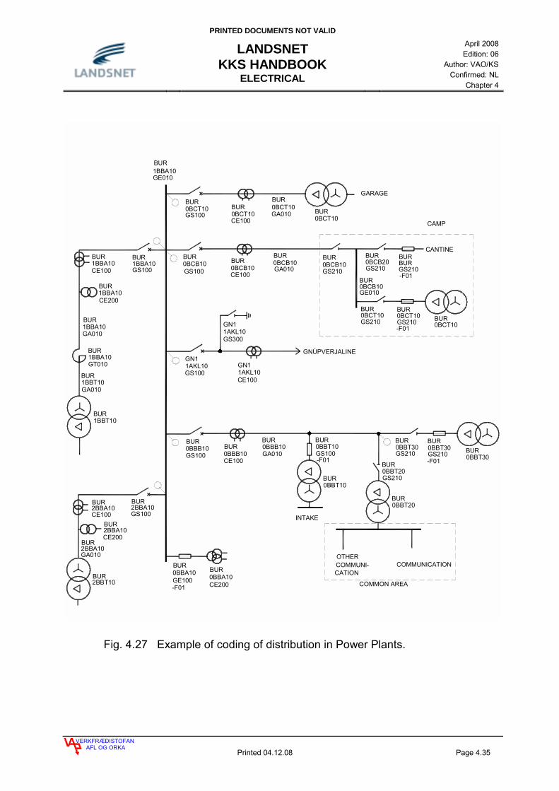
PRINTED DOCUMENTS NOT VALID
LANDSNET KKS HANDBOOK
ELECTRICAL
April 2008 Edition: 06
Author: VAO/KS Confirmed: NL
Chapter 4
VERKFRÆÐISTOFANAFL OG ORKA
Printed 04.12.08 Page 4.35
1BBA10GT010
1BBA10GS100
0BBA10CE200
0BBA10GE100
0BBB10GS100 0BBB10
CE100
1AKL10GS100
1AKL10GS300
1AKL10CE100
GNÚPVERJALINE
0BCT10GS100
0BBT10GS100
GARAGE
OTHER
1BBA10CE100
0BBT20
0BBT10
2BBA10CE200
2BBA10GS100
2BBA10CE100
1BBA10CE200
0BCT10CE100
2BBA10GA010
1BBT10GA010
1BBA10GA010
0BCT10
0BCT10GA010
0BBB10GA010
0BBT20GS210
INTAKE
COMMUNI- COMMUNICATIONCATION
COMMON AREA
1BBT10
2BBT10
1BBA10
0BBT300BBT30GS210
0BBT30GS210
GE010
-F01-F01
-F01
0BCB10
CAMP
0BCB10GS100 0BCB10
CE100GA010
0BCT10
BURGS210
0BCB20GS2100BCB10
GS210
0BCT10GS210
0BCT10GS210
0BCB10
CANTINE
GE010
-F01
-F01GN1
GN1GN1
BUR
BUR
BUR
BUR
BUR
BURBURBURBUR
BUR
BURBUR
BURBUR BUR BUR
BUR
BURBUR
BURBUR
BUR
BURBUR
BUR
BUR
BUR
BUR
BURBUR
BUR
BUR
BUR
BUR
BUR
BURBUR
BUR
BUR
Fig. 4.27 Example of coding of distribution in Power Plants.

PRINTED DOCUMENTS NOT VALID
LANDSNET KKS HANDBOOK
ELECTRICAL
April 2008 Edition: 06
Author: VAO/KS Confirmed: NL
Chapter 4
VERKFRÆÐISTOFANAFL OG ORKA
Printed 04.12.08 Page 4.36
BBB10
BBA10
BFT10
BFT10
BBA10 BBB10
BBB10BBA10
BBA10 BBB10
GS100
GS210 GS210
GS300GS300
GS100 GS100
BFT20GS100
Fig. 4.28 Coding of circuit breakers, disconnectors and earthing switches in a Power Plant.

PRINTED DOCUMENTS NOT VALID
LANDSNET KKS HANDBOOK
ELECTRICAL
April 2008 Edition: 06
Author: VAO/KS Confirmed: NL
Chapter 4
VERKFRÆÐISTOFANAFL OG ORKA
Printed 04.12.08 Page 4.37
_ADL10EU010
_ADL10CE100
_ADL10GS250
_ADL10GS210
_ADL10GS220
_ADL10GS100
_ADL10CE200
_ADL10GS300
LINE BAY
0ADA10
0ADV10
SPARE BUSBARS
MAIN BUSBARS
GE010
GE010
Fig. 4.29 Example of a single phase coding of a 220 kV line bay in a switchyard. See three phase coding in figure 4.30.

PRINTED DOCUMENTS NOT VALID
LANDSNET KKS HANDBOOK
ELECTRICAL
April 2008 Edition: 06
Author: VAO/KS Confirmed: NL
Chapter 4
VERKFRÆÐISTOFANAFL OG ORKA
Printed 04.12.08 Page 4.38
_ADL10EU011
_ADL10EU013
_ADL10GS101
_ADL10GS102
_ADL10GS103
_ADL10GS253
_ADL10GS303
_ADL10GS252
_ADL10GS302
_ADL10GS251
_ADL10GS301
_ADL10GS223
_ADL10GS222
_ADL10GS221
_ADL10GS213
_ADL10GS212
_ADL10GS211
LINE BAY
SPARE BUSBARS
MAIN BUSBARS
_ADL10CE203
_ADL10CE201
_ADL10CE101B
_ADL10CE102B
_ADL10CE103B
_ADL10CE101C
_ADL10CE102C
_ADL10CE103C
_ADL10CE101A
_ADL10CE102A
_ADL10CE103A
0ADV10
0ADV10
0ADV10
GE013
GE012
GE011
0ADA10
0ADA10
0ADA10
GE013
GE012
GE011
Fig. 4.30 Example of three phase coding of a 220 kV line bay in a switchyard. See one phase coding in figure 4.29.

PRINTED DOCUMENTS NOT VALID
LANDSNET KKS HANDBOOK
ELECTRICAL
April 2008 Edition: 06
Author: VAO/KS Confirmed: NL
Chapter 4
VERKFRÆÐISTOFANAFL OG ORKA
Printed 04.12.08 Page 4.39
4.10 EQUIPMENT AND POWER CIRCUIT CODING
When equipment is coded according to the process code, the whole process shall be coded, i.e. all equipment needed for control, protection etc. shall be coded with the same process code the whole way on BDL 1.
0LPB22GS120
0LPB22AH010-F01
0LPB22AH011
-R01
0LPB22AH012
-R01
0LPB22AH020-F01
0LPB22AH021
-R01
0LPB22AH022
-R01
0LPB22AH030-F01
0LPB22AH031
-R01
0LPB22AH032
-R01
0LPB 22AP 010
-M01
M
0LPB22AP010-F02
0LPB22AH010-K01
0LPB22AH020-K01
0LPB22AH030-K01
CONTROL FOR
C
0LPB22AP010-F01
I >
0LPB22GS110
0LPB22EA010
DIUSTRIBUTION BOARD
Fig. 4.31 Example of coding of equipment belonging to heating system for gates.
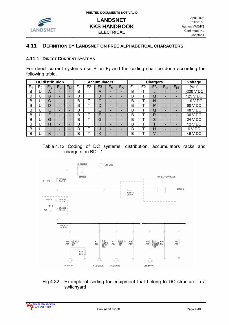
PRINTED DOCUMENTS NOT VALID
LANDSNET KKS HANDBOOK
ELECTRICAL
April 2008 Edition: 06
Author: VAO/KS Confirmed: NL
Chapter 4
VERKFRÆÐISTOFANAFL OG ORKA
Printed 04.12.08 Page 4.40
4.11 DEFINITION BY LANDSNET ON FREE ALPHABETICAL CHARACTERS
4.11.1 DIRECT CURRENT SYSTEMS
For direct current systems use B on F1 and the coding shall be done according the following table.
DC distribution Accumulators Chargers Voltage F1 F2 F3 FN FN F1 F2 F3 FN FN F1 F2 F3 FN FN [Volt] B U A - - B T A - - B T L - - >220 V DC B U B - - B T B - - B T M - - 125 V DC B U C - - B T C - - B T N - - 110 V DC B U D - - B T D - - B T P - - 60 V DC B U E - - B T E - - B T Q - - 48 V DC B U F - - B T F - - B T R - - 36 V DC B U G - - B T G - - B T S - - 24 V DC B U H - - B T H - - B T T - - 12 V DC B U J - - B T J - - B T U - - 6 V DC B U K - - B T K - - B T V - - <6 V DC
Table 4.12 Coding of DC systems, distribution, accumulators racks and chargers on BDL 1.
400 VACCHARGER
110 V BATTERY RACK
F13/14
10
-F29-F30
-F21-F22
-F23-F24
-F25-F26
-F27-F28
-F15-F16
-F49-F50
-F51-F52
GLE-E080 GLE-E090a GLE-E090b GLE-E090c
S10
F11/F12
GLE1AET10GS100-F02
GL11AEL10GS230-F01
0BTC10
0BUC10GD010
0BTC10GS210
0BTN10GS210
0BUC10GS210
0BUC10GS100
0BUC10GD017-F01
0BUC10GD011-F01
0BTN10
Fig 4.32 Example of coding for equipment that belong to DC structure in a switchyard

PRINTED DOCUMENTS NOT VALID
LANDSNET KKS HANDBOOK
ELECTRICAL
April 2008 Edition: 06
Author: VAO/KS Confirmed: NL
Chapter 4
VERKFRÆÐISTOFANAFL OG ORKA
Printed 04.12.08 Page 4.41
4.11.2 CABLES, CONDUCTORS, INTERCONNECTING BOXES, BUSBARS AND HV FEED THROUGH
For cables and installations material use G on A1 and the coding shall be done according the following table.
A1 A2 AN AN AN A3 Item
G A - - - - Cables and conductors G B - - - - Connecting box G C - - - - Transmission line G D - - - - DC-busbar G E - - - - AC-busbar G F - - - - HV feed through G G - - - - HV terminating
Table 4.13 Coding of Cables, conductors, interconnecting boxes, busbars and HV feed through on BDL 2.

PRINTED DOCUMENTS NOT VALID
LANDSNET KKS HANDBOOK
ELECTRICAL
April 2008 Edition: 06
Author: VAO/KS Confirmed: NL
Chapter 4
VERKFRÆÐISTOFANAFL OG ORKA
Printed 04.12.08 Page 4.42
4.12 CODING FIBER OPTIC CABLE AND OPTICAL SYSTEM
In transformer stations and in switchyards in power stations the fiber optic cable shall be coded as the switchyard on BDL ÷1 and as the line it follows on BDL 0. The fiber optic cable itself shall be coded as the line it follows, both on BDL ÷1 and on BDL 0. On BDL 1, F0 shall be coded 0 for the fiber optic cable itself, 1 for the switchyard where it starts in but 2 where it ends, F1 is A, F2 is Y and F3 is P, as in table below. The connecting box for the fiber optic cable shall be coded as GB100 on BDL 3 as in table 4.14
F1 F2 F3 FN FN Búnaður A - - - - Grid and distribution A Y - - - Communication A Y P - - Optical monitoring system
Table 4.14 Coding fiber optic cable
Dæmi: The fiber optic cable between Laxárvirkjun og Rangárvellir would be coded: LA1 LA1 0AYP10 Fiber optic cable LAX LA1 1AYP10 GB100 Connecting box in Laxárvirkjun RAN LA1 2AYP10 GB100 Connecting box in Rangárvellir Name From BDL
÷1 BDL 0
BDL 1 To BDL ÷1
BDL 0
BDL 1
Bjarnarflagslína 1 Bjarnarflag BJA BJ1 1AYP Krafla KRA BJ1 2AYP Hryggstekkur HRY TE1 1AYP Teigarhorn TEH TE1 2AYP Krafla KRA KR2 1AYP Fljótsdalur FLJ KR2 2AYP Laxárvirkjun LAX LA2 1AYP Bjarnarflag BJA LA2 2AYP Rangárvellir RAN LA1 1AYP Laxárvirkjun LAX LA1 2AYP Teigarhorn TEH HO1 1AYP Hólar HOL HO1 2AYP
Table 4.15 BDL ÷1, BDL 0 and BDL 1 for fiber optic cables.

PRINTED DOCUMENTS NOT VALID
LANDSNET KKS HANDBOOK
ELECTRICAL
April 2008 Edition: 06
Author: VAO/KS Confirmed: NL
Chapter 4
VERKFRÆÐISTOFANAFL OG ORKA
Printed 04.12.08 Page 4.43
4.13 RELAY PROTECTION
For relay protection in distribution, transmission and production the coding shall be done according the following tables.
4.13.1 DISTRIBUTION
Relay protection distribution, KKS coding BDL 2 Explanation EY 000 Combined relays, such as I>, Z<, Z>, U>, U<, f>, f<, GENERAL EY 010 EY 020 EY 030 EY 040 EY 050 EY 060 EY 070 EY 080 EY 090 EY 100 Over current, I>, I>>, Io>, Io>>, I> -->, Io> -->, I> inv., Io> inv. GENERAL EY 110 Over current, I>, I>>, Io>, Io>>, I> -->, Io> -->, I> inv., Io> inv. Power transformers EY 120 Over current, I>, I>>, Io>, Io>>, I> -->, Io> -->, I> inv., Io> inv. Lines EY 130 Over current, I>, I>>, Io>, Io>>, I> -->, Io> -->, I> inv., Io> inv. Capacitors EY 140 Over current, I>, I>>, Io>, Io>>, I> -->, Io> -->, I> inv., Io> inv. Own consumption EY 150 Over current, I>, I>>, Io>, Io>>, I> -->, Io> -->, I> inv., Io> inv. Bustie EY 160 EY 170 EY 180 Motor protection EY 190 EY 200 Differential current Id>, GENERAL EY 210 Differential current Id>, Power transformer EY 220 Differential current Id>, Lines EY 230 Differential current Id>, Capacitors EY 240 Differential current Id>, Own consumption EY 250 EY 260 EY 270 Busbar protection EY 280 EY 290 EY 300 Under voltage / over voltage U<, U>, GENERAL EY 310 Under voltage / over voltage U<, U>, Power transformers EY 320 Under voltage / over voltage U<, U>, Lines EY 330 Under voltage / over voltage U<, U>, Capacitors EY 340 Under voltage / over voltage U<, U>, Own consumption EY 350

PRINTED DOCUMENTS NOT VALID
LANDSNET KKS HANDBOOK
ELECTRICAL
April 2008 Edition: 06
Author: VAO/KS Confirmed: NL
Chapter 4
VERKFRÆÐISTOFANAFL OG ORKA
Printed 04.12.08 Page 4.44
EY 360 EY 370 EY 380 EY 390 EY 400 Under frequency / over frequency f<, f>, GENERAL EY 410 Under frequency / over frequency f<, f>, Power transformers EY 420 Under frequency / over frequency f<, f>, Lines EY 430 Under frequency / over frequency f<, f>, Capacitors EY 440 Under frequency / over frequency f<, f>, Own consumption EY 450 EY 460 EY 470 EY 480 EY 490 EY 500 Distance protection Z<, >, GENERAL EY 510 Distance protection Z<, >, Power transformers EY 520 Distance protection Z<, >, Lines EY 530 EY 540 EY 550 EY 560 EY 570 Phase selection relays EY 580 Impedance relays for transformers EY 590 EY 600 Breaker Failure, GENERAL EY 610 Breaker Failure, Power transformers EY 620 Breaker Failure, Lines EY 630 Breaker Failure, Capacitors EY 640 Breaker Failure, Bustie EY 650 EY 660 EY 670 EY 680 EY 690 EY 700 EY 710 EY 720 EY 730 EY 740 EY 750 EY 760 EY 770 EY 780 EY 790 EY 800

PRINTED DOCUMENTS NOT VALID
LANDSNET KKS HANDBOOK
ELECTRICAL
April 2008 Edition: 06
Author: VAO/KS Confirmed: NL
Chapter 4
VERKFRÆÐISTOFANAFL OG ORKA
Printed 04.12.08 Page 4.45
EY 810 EY 820 EY 830 EY 840 EY 850 EY 860 EY 870 EY 880 EY 890 EY 900 Relay protection undefined EY 910 Auxiliary relays EY 920 Reclosing equipment EY 930 Synchro-Check EY 940 Synchronizing equipment EY 950 Fault location/Registration EY 960 Voltage regulation EY 970 Communication equipment, isolated EY 980 EY 990
Table 4.16 Coding for relay protection in distribution on BDL 2
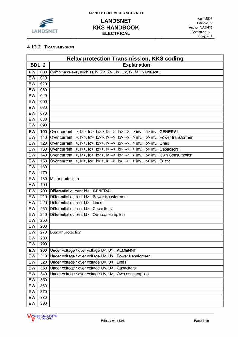
PRINTED DOCUMENTS NOT VALID
LANDSNET KKS HANDBOOK
ELECTRICAL
April 2008 Edition: 06
Author: VAO/KS Confirmed: NL
Chapter 4
VERKFRÆÐISTOFANAFL OG ORKA
Printed 04.12.08 Page 4.46
4.13.2 TRANSMISSION
Relay protection Transmission, KKS coding BDL 2 Explanation
EW 000 Combine relays, such as I>, Z<, Z>, U>, U<, f>, f<, GENERAL EW 010 EW 020 EW 030 EW 040 EW 050 EW 060 EW 070 EW 080 EW 090 EW 100 Over current, I>, I>>, Io>, Io>>, I> -->, Io> -->, I> inv., Io> inv. GENERAL EW 110 Over current, I>, I>>, Io>, Io>>, I> -->, Io> -->, I> inv., Io> inv. Power transformer EW 120 Over current, I>, I>>, Io>, Io>>, I> -->, Io> -->, I> inv., Io> inv. Lines EW 130 Over current, I>, I>>, Io>, Io>>, I> -->, Io> -->, I> inv., Io> inv. Capacitors EW 140 Over current, I>, I>>, Io>, Io>>, I> -->, Io> -->, I> inv., Io> inv. Own Consumption EW 150 Over current, I>, I>>, Io>, Io>>, I> -->, Io> -->, I> inv., Io> inv. Bustie EW 160 EW 170 EW 180 Motor protection EW 190 EW 200 Differential current Id>, GENERAL EW 210 Differential current Id>, Power transformer EW 220 Differential current Id>, Lines EW 230 Differential current Id>, Capacitors EW 240 Differential current Id>, Own consumption EW 250 EW 260 EW 270 Busbar protection EW 280 EW 290 EW 300 Under voltage / over voltage U<, U>, ALMENNT EW 310 Under voltage / over voltage U<, U>, Power transformer EW 320 Under voltage / over voltage U<, U>, Lines EW 330 Under voltage / over voltage U<, U>, Capacitors EW 340 Under voltage / over voltage U<, U>, Own consumption EW 350 EW 360 EW 370 EW 380 EW 390

PRINTED DOCUMENTS NOT VALID
LANDSNET KKS HANDBOOK
ELECTRICAL
April 2008 Edition: 06
Author: VAO/KS Confirmed: NL
Chapter 4
VERKFRÆÐISTOFANAFL OG ORKA
Printed 04.12.08 Page 4.47
EW 400 Under frequency / over frequency f<, f>, GENERAL EW 410 Under frequency / over frequency f<, f>, Power transformer EW 420 Under frequency / over frequency f<, f>, Lines EW 430 Under frequency / over frequency f<, f>, Capacitors EW 440 Under frequency / over frequency f<, f>, Own consumption EW 450 EW 460 EW 470 EW 480 EW 490 EW 500 Distance protection Z<, >, GENERAL EW 510 Distance protection Z<, >, Power transformer EW 520 Distance protection Z<, >, Lines EW 530 EW 540 EW 550 EW 560 EW 570 Phase selection relays EW 580 Impedance relays for transformers EW 590 EW 600 Breaker Failure, GENERAL EW 610 Breaker Failure, Power transformer EW 620 Breaker Failure, Lines EW 630 Breaker Failure, Capacitors EW 640 Breaker Failure, Bustie EW 650 EW 660 EW 670 EW 680 EW 690 EW 700 EW 710 EW 720 EW 730 EW 740 EW 750 EW 760 EW 770 EW 780 EW 790 EW 800 EW 810 EW 820 EW 830 EW 840

PRINTED DOCUMENTS NOT VALID
LANDSNET KKS HANDBOOK
ELECTRICAL
April 2008 Edition: 06
Author: VAO/KS Confirmed: NL
Chapter 4
VERKFRÆÐISTOFANAFL OG ORKA
Printed 04.12.08 Page 4.48
EW 850 EW 860 EW 870 EW 880 EW 890 EW 900 Relay protection undefined EW 910 Auxiliary relays EW 920 Reclosing equipment EW 930 Synchro-Check EW 940 Synchronizing equipment EW 950 Fault location / registration EW 960 Voltage regulation EW 970 Communication equipment, isolated EW 980 EW 990
Table 4.17 Coding for relay protection in transmission on BDL 2
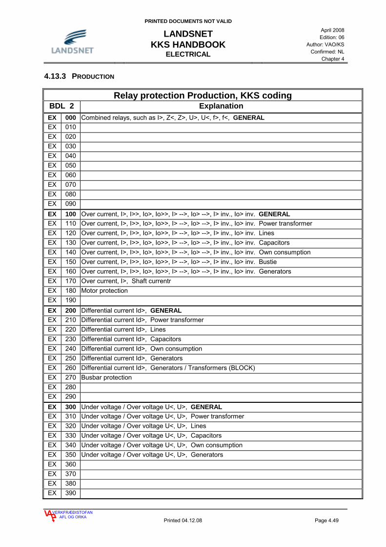
PRINTED DOCUMENTS NOT VALID
LANDSNET KKS HANDBOOK
ELECTRICAL
April 2008 Edition: 06
Author: VAO/KS Confirmed: NL
Chapter 4
VERKFRÆÐISTOFANAFL OG ORKA
Printed 04.12.08 Page 4.49
4.13.3 PRODUCTION
Relay protection Production, KKS coding BDL 2 Explanation EX 000 Combined relays, such as I>, Z<, Z>, U>, U<, f>, f<, GENERAL EX 010 EX 020 EX 030 EX 040 EX 050 EX 060 EX 070 EX 080 EX 090 EX 100 Over current, I>, I>>, Io>, Io>>, I> -->, Io> -->, I> inv., Io> inv. GENERAL EX 110 Over current, I>, I>>, Io>, Io>>, I> -->, Io> -->, I> inv., Io> inv. Power transformer EX 120 Over current, I>, I>>, Io>, Io>>, I> -->, Io> -->, I> inv., Io> inv. Lines EX 130 Over current, I>, I>>, Io>, Io>>, I> -->, Io> -->, I> inv., Io> inv. Capacitors EX 140 Over current, I>, I>>, Io>, Io>>, I> -->, Io> -->, I> inv., Io> inv. Own consumption EX 150 Over current, I>, I>>, Io>, Io>>, I> -->, Io> -->, I> inv., Io> inv. Bustie EX 160 Over current, I>, I>>, Io>, Io>>, I> -->, Io> -->, I> inv., Io> inv. Generators EX 170 Over current, I>, Shaft currentr EX 180 Motor protection EX 190 EX 200 Differential current Id>, GENERAL EX 210 Differential current Id>, Power transformer EX 220 Differential current Id>, Lines EX 230 Differential current Id>, Capacitors EX 240 Differential current Id>, Own consumption EX 250 Differential current Id>, Generators EX 260 Differential current Id>, Generators / Transformers (BLOCK) EX 270 Busbar protection EX 280 EX 290 EX 300 Under voltage / Over voltage U<, U>, GENERAL EX 310 Under voltage / Over voltage U<, U>, Power transformer EX 320 Under voltage / Over voltage U<, U>, Lines EX 330 Under voltage / Over voltage U<, U>, Capacitors EX 340 Under voltage / Over voltage U<, U>, Own consumption EX 350 Under voltage / Over voltage U<, U>, Generators EX 360 EX 370 EX 380 EX 390

PRINTED DOCUMENTS NOT VALID
LANDSNET KKS HANDBOOK
ELECTRICAL
April 2008 Edition: 06
Author: VAO/KS Confirmed: NL
Chapter 4
VERKFRÆÐISTOFANAFL OG ORKA
Printed 04.12.08 Page 4.50
EX 400 Under frequency / over frequency f<, f>, GENERAL EX 410 Under frequency / over frequency f<, f>, Power transformer EX 420 Under frequency / over frequency f<, f>, Lines EX 430 Under frequency / over frequency f<, f>, Capacitors EX 440 Under frequency / over frequency f<, f>, Own consumption EX 450 Under frequency / over frequency f<, f>, Generators EX 460 EX 470 EX 480 EX 490 EX 500 Distance protection Z<, >, GENERAL EX 510 Distance protection Z<, >, Power transformers EX 520 Distance protection Z<, >, Lines EX 530 EX 540 EX 550 Distance protection Z<, >, Generators EX 560 Reverse power P<-- EX 570 Phase selection relays EX 580 Impedance relays for transformers EX 590 EX 600 Breaker Failure, GENERAL EX 610 Breaker Failure, Power transformer EX 620 Breaker Failure, Lines EX 630 Breaker Failure, Capacitors EX 640 Breaker Failure, Bustie EX 650 Breaker Failure, Generators EX 660 EX 670 EX 680 EX 690 EX 700 Rotor earth Re<, Stator earth Se, GENERAL EX 710 Rotor earth Re< EX 720 Stator earth Se, 100% inj. EX 730 Stator earth Se, 100% 3. Harm. EX 740 Stator earth Se, 95% Un EX 750 Stator earth Se, 80% Un EX 760 EX 770 EX 780 EX 790 EX 800 Neg.-Seq Insc>, Therm. Overload θ>, Loss of Ex. Ф<, Over excitation U/f>, Under excitation U/f<
GENERAL EX 810 Neg.-Seq Insc> EX 820 Therm. Overload θ> EX 830 Loss of Ex. Ф<

PRINTED DOCUMENTS NOT VALID
LANDSNET KKS HANDBOOK
ELECTRICAL
April 2008 Edition: 06
Author: VAO/KS Confirmed: NL
Chapter 4
VERKFRÆÐISTOFANAFL OG ORKA
Printed 04.12.08 Page 4.51
EX 840 Over excitation U/f> EX 850 Under excitation U/f< EX 860 EX 870 EX 880 EX 890 EX 900 Relay protection undefined EX 910 Auxiliary relay EX 920 Reclosing equipment EX 930 Synchro-Check EX 940 Synchronizing equipment EX 950 Fault location / registration EX 960 Voltage regulation EX 970 Communication equipment, isolated EX 980 EX 990
Table 4.18 Coding for relay protection in production on BDL 2

PRINTED DOCUMENTS NOT VALID
LANDSNET KKS HANDBOOK
POINT OF INSTALLATION CODE
December 2008
Edition: 07 Author: VAO/KS
Confirmed: NL Chapter 5
VERKFRÆÐISTOFANAFL OG ORKA
Printed 04.12.08 Page 5.1
5. POINT OF INSTALLATION CODE 2
5.1 POINT OF INSTALLATION 2 5.1.1 CODING OF HIGH-VOLTAGE CUBICLES IN TRANSFORMER STATIONS AND FOR DISTRIBUTION OUTSIDE OF POWER PLANTS 5 5.1.2 CODING OF HIGH-VOLTAGE CUBICLES IN POWER PLANTS AND FOR LOCAL DISTRIBUTION IN POWER PLANTS 5 5.1.3 CODING OF CONTROL-, MEASURING-, SIGNALING-, AND PROTECTION CUBICLES 6
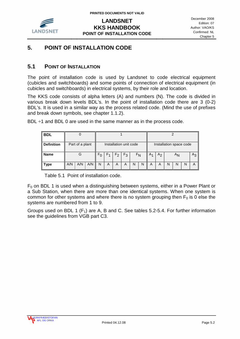
PRINTED DOCUMENTS NOT VALID
LANDSNET KKS HANDBOOK
POINT OF INSTALLATION CODE
December 2008
Edition: 07 Author: VAO/KS
Confirmed: NL Chapter 5
VERKFRÆÐISTOFANAFL OG ORKA
Printed 04.12.08 Page 5.2
5. POINT OF INSTALLATION CODE
5.1 POINT OF INSTALLATION
The point of installation code is used by Landsnet to code electrical equipment (cubicles and switchboards) and some points of connection of electrical equipment (in cubicles and switchboards) in electrical systems, by their role and location. The KKS code consists of alpha letters (A) and numbers (N). The code is divided in various break down levels BDL’s. In the point of installation code there are 3 (0-2) BDL’s. It is used in a similar way as the process related code. (Mind the use of prefixes and break down symbols, see chapter 1.1.2).
BDL ÷1 and BDL 0 are used in the same manner as in the process code.
BDL 0 1 2
Definition Part of a plant Installation unit code Installation space code
Name G F0 F1 F2 F3 FN A1 A2 AN A3
Type A/N A/N A/N N A A A N N A A N N N A
Table 5.1 Point of installation code.
F0 on BDL 1 is used when a distinguishing between systems, either in a Power Plant or a Sub Station, when there are more than one identical systems. When one system is common for other systems and where there is no system grouping then F0 is 0 else the systems are numbered from 1 to 9. Groups used on BDL 1 (F1) are A, B and C. See tables 5.2-5.4. For further information see the guidelines from VGB part C3.

PRINTED DOCUMENTS NOT VALID
LANDSNET KKS HANDBOOK
POINT OF INSTALLATION CODE
December 2008
Edition: 07 Author: VAO/KS
Confirmed: NL Chapter 5
VERKFRÆÐISTOFANAFL OG ORKA
Printed 04.12.08 Page 5.3
F0 F1 F2 F3 FN FN Location - A D - - - 220 (245) kV system - A E - - - 110 (150) kV system - A F - - - 60 (72) kV system - A H - - - 30 (35) kV system - A K - - - 10 (15) kV system - A L - - - 6 (5) kV system - A N - - - < 1 kV system - A P - - - Control consoles - A Q - - - Measuring- and metering equipment - A R - - - Protection equipment - A S - - - Decentralized panels and cabinets - A T - - - Transformer equipment - A U - - - Open-loop control, checkback and auxiliary equipment - A V - - - Control and relay cubicles - A W - - - Instrument panels - A X - - - Central equipment - A Y - - - Communication equipment
Table 5.2 Group A codes (grid and distribution) which are used by Landsnet in point of installation code, BDL 1 ( F2 ).
F0 F1 F2 F3 FN FN Location - B A - - - Power production - B B - - - High voltage distribution boards and transformers, normal system - B C - - - High voltage distribution boards and transformers, general-purpose - B D - - - High voltage distribution boards and transformers, emergency power
system - B F - - - Low voltage main distribution boards and transformers, normal system - B H - - - Low voltage main distribution boards and transformers, general-purpose - B J - - - Low voltage subdistribution boards and transformers, normal system - B L - - - Low voltage main distribution boards and transformers, general purpose - B M - - - Low voltage subdistribution boards and transformers, (diesel) emergency
power system 1 - B N - - - Low voltage subdistribution boards and transformers, (diesel) emergency
power system 2 (protected against external impact) B P - - - Power installations for large variable-speed drives, e.g. feed water pump
excitation equipment, not power adjusters in switchgear B R - - - Low voltage distribution, emergency power system 1 (converter) - B T - - - Battery systems (batteries and chargers) - B U - - - Direct voltage distribution boards, normal system - B V - - - Direct voltage distribution boards, emergency power system 1 - B W - - - Direct voltage distribution boards, emergency power system 2 - B X - - - Fluid supply system for control and protection equipment - B Y - - - Control and protection equipment
Table 5.3 Group B codes (power transmission and auxiliary power supply) which are used by Landsnet in point of installation code, BDL 1 (F2).

PRINTED DOCUMENTS NOT VALID
LANDSNET KKS HANDBOOK
POINT OF INSTALLATION CODE
December 2008
Edition: 07 Author: VAO/KS
Confirmed: NL Chapter 5
VERKFRÆÐISTOFANAFL OG ORKA
Printed 04.12.08 Page 5.4
F0 F1 F2 F3 FN FN Location
- C A - - - Protective interlocks - C B - - - Functional group control, sub loop control - C C - - - Binary signal conditioning - C D - - - Drive control interface - C E - - - Annunciation - C F - - - Measuring, recording - C G - - - Closed-loop control (excl. power section) - C H - - - Low voltage main distribution boards and transformers, general-purpose - C J - - - Unit coordination level - C K - - - Process computer system C M - - - Instrumentation and control equipment C N - - - Instrumentation and control equipment - C T - - - Instrumentation and control equipment - C U - - - Closed-loop control (power section) - C V - - - Marshalling racks - C W - - - Control rooms - C X - - - Local control station - C Y - - - Communication equipment
Table 5.4 Group C codes (instrumentation and control equipment) which are used by Landsnet in point of installation code, BDL 1 (F2).

PRINTED DOCUMENTS NOT VALID
LANDSNET KKS HANDBOOK
POINT OF INSTALLATION CODE
December 2008
Edition: 07 Author: VAO/KS
Confirmed: NL Chapter 5
VERKFRÆÐISTOFANAFL OG ORKA
Printed 04.12.08 Page 5.5
5.1.1 CODING OF HIGH-VOLTAGE CUBICLES IN SUB STATIONS AND FOR DISTRIBUTION OUTSIDE OF POWER PLANTS
Coding of cubicles shall be as shown on fig 5.1. They shall have the same code as the busbar in the respective cubicles when possible. This applies for high-voltage cubicles in distribution systems and for high-voltage cubicles in bays for systems outside of Power Plants and Sub Stations. Cubicles are counted from the left to the right, when in front of them.
=AKA00+AKA01 +AKA02 +AKA03 +AKA04 +AKA05 +AKA06 +AKA07
Fig. 5.1 Coding of 11 kV cubicles for circuit breakers, common busbar, cubicles in one row.
5.1.2 CODING OF HIGH-VOLTAGE CUBICLES IN POWER PLANTS AND FOR LOCAL DISTRIBUTION IN POWER PLANTS
Coding of cubicles shall be as shown on fig 5.2 and 5.3. They shall have the same code as the busbar in the respective cubicle when possible. This applies for high-voltage cubicles in Power Plants and for high-voltage cubicles in bays for Power Plant distribution systems. Cubicles are counted from the left to the right, when in front of them.

PRINTED DOCUMENTS NOT VALID
LANDSNET KKS HANDBOOK
POINT OF INSTALLATION CODE
December 2008
Edition: 07 Author: VAO/KS
Confirmed: NL Chapter 5
VERKFRÆÐISTOFANAFL OG ORKA
Printed 04.12.08 Page 5.6
Fig. 5.2 Coding of cubicles, common busbar, cubicles in one row.
Fig. 5.3 Coding of cubicles, no common busbar.
5.1.3 CODING OF CONTROL-, MEASURING-, SIGNALING-, AND PROTECTION CUBICLES
Coding of cubicles for control-, measuring-, signaling- and protection equipment shall be according to fig. 5.4 and 5.5. This applies for all cubicles for control-, measuring-, signaling- and protection equipment Cubicles are counted from the left to the right, when in front of them.
=BBA00
+BBA01 +BBA02 +BBB01 +BBB02 +BBC01 +BBC02
=BBB00 =BBC00
=BBA00
+BBA01 +BBA02 +BBA03 +BBA04 +BBA05 +BBA06 +BBA07

PRINTED DOCUMENTS NOT VALID
LANDSNET KKS HANDBOOK
POINT OF INSTALLATION CODE
December 2008
Edition: 07 Author: VAO/KS
Confirmed: NL Chapter 5
VERKFRÆÐISTOFANAFL OG ORKA
Printed 04.12.08 Page 5.7
+AWF01 +AWF02 +AWF03 +AWF04 +AWF05 +AWF06 +AWF07V
A
V
A
V
A
OVERCURRENT
VOLTAGE REG.
PROTECTION
PROTECTION
OVERCURRENT
A-PROTECTION
B-PROTECTION
Fig. 5.4 Coding of control- and relay cubicles for a switchyard.
Fig. 5.5 Coding of control and protection equipment for Power Plants.
+1CHA01 +1CHA02 +2CHA01 +2CHA02 +3CHA01 +3CHA02
MW
kVA
V
A
%
m/s
P
T
MW
kVA
V
A
%
m/s
P
T
MW
kVA
V
A
%
m/s
P
T

PRINTED DOCUMENTS NOT VALID
LANDSNET KKS HANDBOOK
LOCATION CODE
December 2008
Edition: 07 Author: VAO/KS
Confirmed: NL Chapter 6
VERKFRÆÐISTOFANAFL OG ORKA
Printed 04.12.08 Page 6.1
6 LOCATION CODE 2
6.1 CODING OF STRUCTURES 2

PRINTED DOCUMENTS NOT VALID
LANDSNET KKS HANDBOOK
LOCATION CODE
December 2008
Edition: 07 Author: VAO/KS
Confirmed: NL Chapter 6
VERKFRÆÐISTOFANAFL OG ORKA
Printed 04.12.08 Page 6.2
6 LOCATION CODE
6.1 CODING OF STRUCTURES
The location code is used by Landsnet to code structures like dams, tunnels, buildings and part of buildings like rooms etc. The location code is also used to code the location of machinary in a similar way as the point of installation code is used for electrical equipment. The KKS code consists of alpha letters (A) and numbers (N). The code is divided in breakdown levels (BDL´s). The location code has 3 (0-2) BDL´s which are used in a similar way as the point of installation code (Note: Use of prefixes and breakdown symbols, see chapter 1.1.2). BDL ÷1 and BDL 0 are used in the same manner as in the process code.
BDL 0 1 2
Definition Part of a Plant
Structure code Room code
Name G F0 F1 F2 F3 FN A1 A2 AN A3
Type of key A or N N A A A N N A A N N N A
Table 6.1 Location code, structure.
F0 on BDL 1 is used where distinction between systems is needed, either in Power Plants or in Sub Stations, where more than one identical systems exists. When one system is common for other systems and identical and there is no system grouping then F0 is 0, otherwise the systems are numbered from 1 to 9. All structures coded with the location code have the letter U on BDL 1 ( F1). The next two letters (F2,F3) are normally the two first letters from the process code which is typical or dominating for the structure. An example is a structure for the gates, which has the code ULP, as the gates are coded on BDL 1, with LP_ in the two first designation places for data characters. In table 6.2 the main group of structures is listed in the same manner as the KKS-code describes in VGB, book B2.

PRINTED DOCUMENTS NOT VALID
LANDSNET KKS HANDBOOK
LOCATION CODE
December 2008
Edition: 07 Author: VAO/KS
Confirmed: NL Chapter 6
VERKFRÆÐISTOFANAFL OG ORKA
Printed 04.12.08 Page 6.3
F0 F1 F2 F3 FN FN Text - U A - - - Structures for grid and distribution systems - U B - - - Structures for power transmission and auxiliary power supply - U C - - - Structures for instrumentation and control - U E - - - Structures for conventional fuel supply and residues - U G - - - Structures for water supply and disposal - U H - - - Structures for conventional heat generation - U L - - - Structures for steam-, water-, gas-cycles - U M - - - Structures for main machine sets - U N - - - Structures for process energy supply - U P - - - Structures for circulating (cooling) water systems - U S - - - Structures for ancillary systems - U T - - - Structures for auxiliary systems - U U - - - Shaft structures - U X - - - Structures for external systems (power plant specific) - U Y - - - General service structures - U Z - - - Structures for transport, traffic, fencing, gardens and other purposes
Table 6.2 Location codes, F1 and F2 used by Landsnet.
If a structure is hosting equipment coded with different KKS codes, this structure shall be coded on F2, according to the code dominating or typical for the structure. For coding of the structure itself the BDL 1 is sufficient. Coding of rooms inside structures is according to the official KKS code from VGB on BDL 2. In case of coding of rooms and floors in structures, the guidelines from VGB, part B2 shall be used.
PRINTED DOCUMENTS NOT VALID
LANDSNET KKS HANDBOOK
IDENTIFICATION OF CABLES
December 2008
Edition: 07 Author: VAO/KS
Confirmed: NL Chapter 7
VERKFRÆÐISTOFANAFL OG ORKA
Printed 04.12.08 Page 7.1
7 IDENTIFICATION OF CABLES 2
7.1 CABLES 2 7.1.1 CONDUCTOR IDENTIFICATION IN CABLES 3 7.2 WIRING WITHIN CUBICLES 4
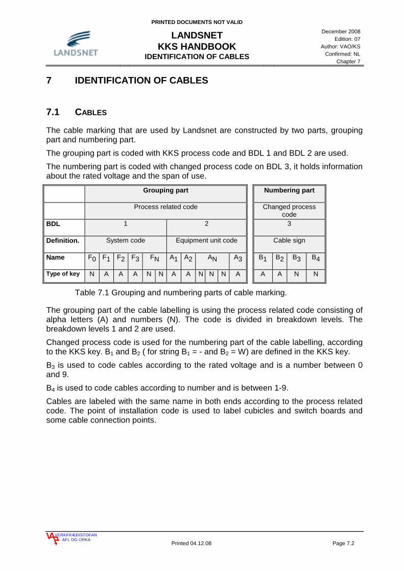
PRINTED DOCUMENTS NOT VALID
LANDSNET KKS HANDBOOK
IDENTIFICATION OF CABLES
December 2008
Edition: 07 Author: VAO/KS
Confirmed: NL Chapter 7
VERKFRÆÐISTOFANAFL OG ORKA
Printed 04.12.08 Page 7.2
7 IDENTIFICATION OF CABLES
7.1 CABLES
The cable marking that are used by Landsnet are constructed by two parts, grouping part and numbering part. The grouping part is coded with KKS process code and BDL 1 and BDL 2 are used. The numbering part is coded with changed process code on BDL 3, it holds information about the rated voltage and the span of use.
Grouping part Numbering part
Process related code Changed process code
BDL 1 2 3
Definition. System code Equipment unit code Cable sign
Name F0 F1 F2 F3 FN A1 A2 AN A3 B1 B2 B3 B4
Type of key N A A A N N A A N N N A A A N N
Table 7.1 Grouping and numbering parts of cable marking.
The grouping part of the cable labelling is using the process related code consisting of alpha letters (A) and numbers (N). The code is divided in breakdown levels. The breakdown levels 1 and 2 are used. Changed process code is used for the numbering part of the cable labelling, according to the KKS key. B1 and B2 ( for string B1 = - and B2 = W) are defined in the KKS key. B3 is used to code cables according to the rated voltage and is a number between 0 and 9. B4 is used to code cables according to number and is between 1-9. Cables are labeled with the same name in both ends according to the process related code. The point of installation code is used to label cubicles and switch boards and some cable connection points.
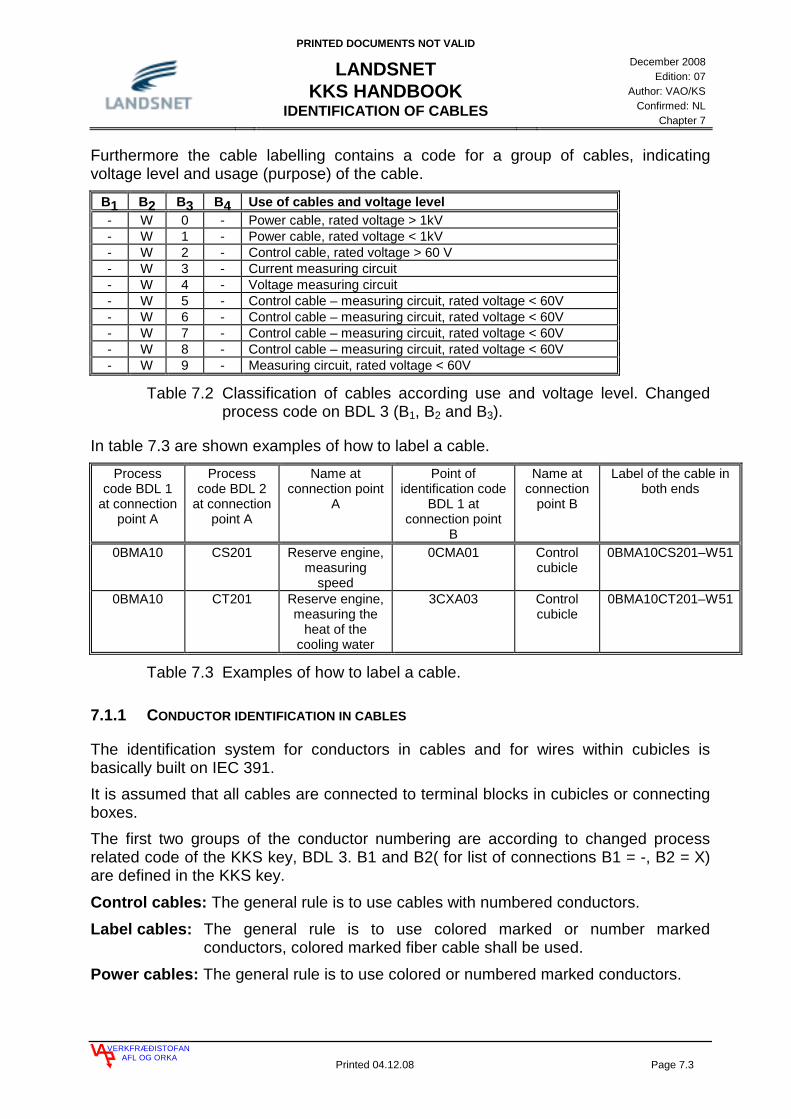
PRINTED DOCUMENTS NOT VALID
LANDSNET KKS HANDBOOK
IDENTIFICATION OF CABLES
December 2008
Edition: 07 Author: VAO/KS
Confirmed: NL Chapter 7
VERKFRÆÐISTOFANAFL OG ORKA
Printed 04.12.08 Page 7.3
Furthermore the cable labelling contains a code for a group of cables, indicating voltage level and usage (purpose) of the cable.
B1 B2 B3 B4 Use of cables and voltage level - W 0 - Power cable, rated voltage > 1kV - W 1 - Power cable, rated voltage < 1kV - W 2 - Control cable, rated voltage > 60 V - W 3 - Current measuring circuit - W 4 - Voltage measuring circuit - W 5 - Control cable – measuring circuit, rated voltage < 60V - W 6 - Control cable – measuring circuit, rated voltage < 60V - W 7 - Control cable – measuring circuit, rated voltage < 60V - W 8 - Control cable – measuring circuit, rated voltage < 60V - W 9 - Measuring circuit, rated voltage < 60V
Table 7.2 Classification of cables according use and voltage level. Changed process code on BDL 3 (B1, B2 and B3).
In table 7.3 are shown examples of how to label a cable.
Process code BDL 1
at connection point A
Process code BDL 2
at connection point A
Name at connection point
A
Point of identification code
BDL 1 at connection point
B
Name at connection
point B
Label of the cable in both ends
0BMA10 CS201 Reserve engine, measuring
speed
0CMA01 Control cubicle
0BMA10CS201–W51
0BMA10 CT201 Reserve engine, measuring the
heat of the cooling water
3CXA03 Control cubicle
0BMA10CT201–W51
Table 7.3 Examples of how to label a cable.
7.1.1 CONDUCTOR IDENTIFICATION IN CABLES
The identification system for conductors in cables and for wires within cubicles is basically built on IEC 391. It is assumed that all cables are connected to terminal blocks in cubicles or connecting boxes. The first two groups of the conductor numbering are according to changed process related code of the KKS key, BDL 3. B1 and B2( for list of connections B1 = -, B2 = X) are defined in the KKS key.
Control cables: The general rule is to use cables with numbered conductors.
Label cables: The general rule is to use colored marked or number marked conductors, colored marked fiber cable shall be used.
Power cables: The general rule is to use colored or numbered marked conductors.
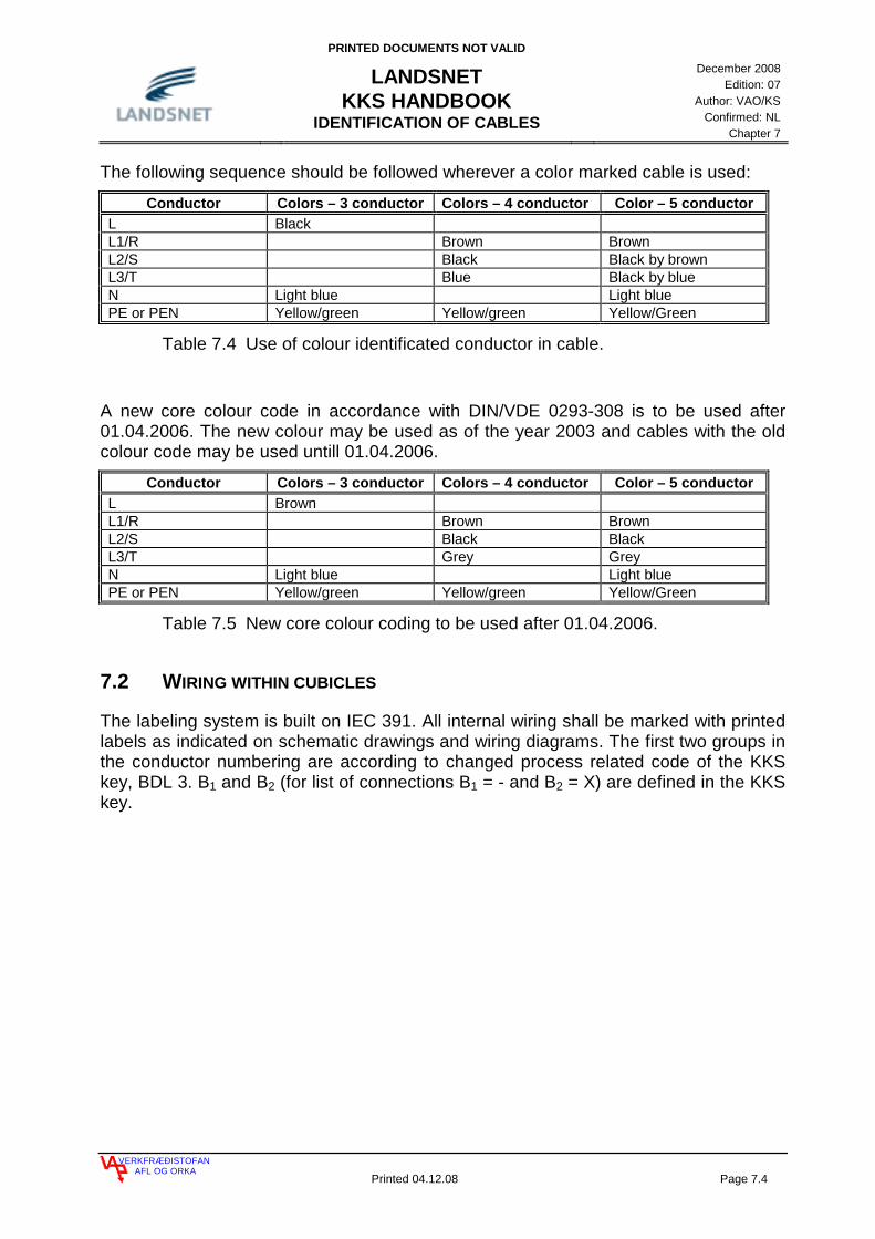
PRINTED DOCUMENTS NOT VALID
LANDSNET KKS HANDBOOK
IDENTIFICATION OF CABLES
December 2008
Edition: 07 Author: VAO/KS
Confirmed: NL Chapter 7
VERKFRÆÐISTOFANAFL OG ORKA
Printed 04.12.08 Page 7.4
The following sequence should be followed wherever a color marked cable is used:
Conductor Colors – 3 conductor Colors – 4 conductor Color – 5 conductor L Black L1/R Brown Brown L2/S Black Black by brown L3/T Blue Black by blue N Light blue Light blue PE or PEN Yellow/green Yellow/green Yellow/Green
Table 7.4 Use of colour identificated conductor in cable.
A new core colour code in accordance with DIN/VDE 0293-308 is to be used after 01.04.2006. The new colour may be used as of the year 2003 and cables with the old colour code may be used untill 01.04.2006.
Conductor Colors – 3 conductor Colors – 4 conductor Color – 5 conductor L Brown L1/R Brown Brown L2/S Black Black L3/T Grey Grey N Light blue Light blue PE or PEN Yellow/green Yellow/green Yellow/Green
Table 7.5 New core colour coding to be used after 01.04.2006.
7.2 WIRING WITHIN CUBICLES
The labeling system is built on IEC 391. All internal wiring shall be marked with printed labels as indicated on schematic drawings and wiring diagrams. The first two groups in the conductor numbering are according to changed process related code of the KKS key, BDL 3. B1 and B2 (for list of connections B1 = - and B2 = X) are defined in the KKS key.

PRINTED DOCUMENTS NOT VALID
LANDSNET KKS HANDBOOK
IDENTIFICATION OF C&I EQUIPMENT
December 2008
Edition: 07 Author: VAO/KS
Confirmed: NL Chapter 8
VERKFRÆÐISTOFANAFL OG ORKA
Printed 04.12.08 Page 8.1
8. IDENTIFICATION OF I&C EQUIPMENT 2
8.1 SIGNAL IDENTIFICATION 2 8.1.1 GENERAL SIGNAL DESIGNATION 2 8.1.2 INDIVIDUAL SIGNAL DESIGNATION 3
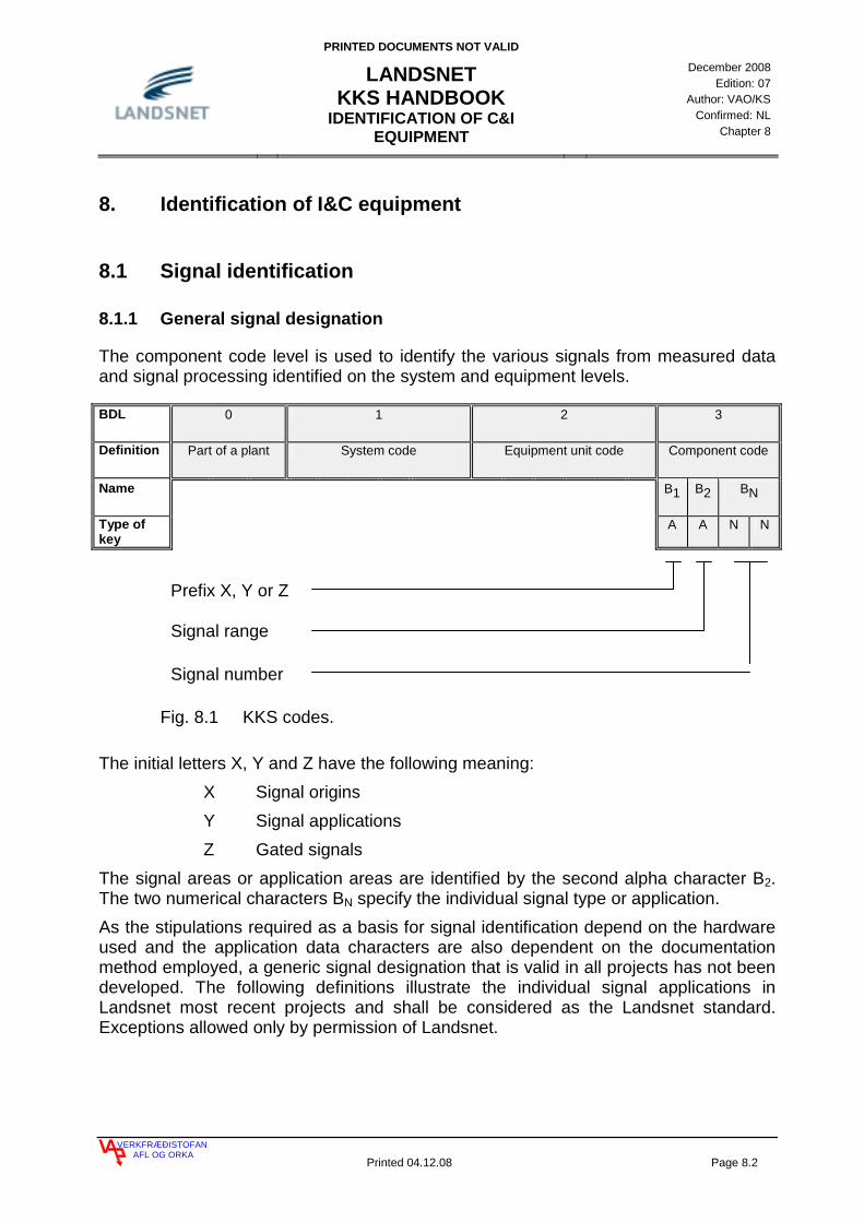
PRINTED DOCUMENTS NOT VALID
LANDSNET KKS HANDBOOK
IDENTIFICATION OF C&I EQUIPMENT
December 2008
Edition: 07 Author: VAO/KS
Confirmed: NL Chapter 8
VERKFRÆÐISTOFANAFL OG ORKA
Printed 04.12.08 Page 8.2
8. Identification of I&C equipment
8.1 Signal identification
8.1.1 General signal designation
The component code level is used to identify the various signals from measured data and signal processing identified on the system and equipment levels.
BDL 0 1 2 3
Definition Part of a plant System code Equipment unit code Component code
Name B1 B2 BN
Type of key
A A N N
Fig. 8.1 KKS codes.
The initial letters X, Y and Z have the following meaning: X Signal origins Y Signal applications Z Gated signals
The signal areas or application areas are identified by the second alpha character B2. The two numerical characters BN specify the individual signal type or application. As the stipulations required as a basis for signal identification depend on the hardware used and the application data characters are also dependent on the documentation method employed, a generic signal designation that is valid in all projects has not been developed. The following definitions illustrate the individual signal applications in Landsnet most recent projects and shall be considered as the Landsnet standard. Exceptions allowed only by permission of Landsnet.
Signal range
Signal number
Prefix X, Y or Z

PRINTED DOCUMENTS NOT VALID
LANDSNET KKS HANDBOOK
IDENTIFICATION OF C&I EQUIPMENT
December 2008
Edition: 07 Author: VAO/KS
Confirmed: NL Chapter 8
VERKFRÆÐISTOFANAFL OG ORKA
Printed 04.12.08 Page 8.3
8.1.2 Individual signal designation
Individual designation list for signal letters and signal numbers.
Code Description Type X Signal origins XA Binary signals - Automatic control VARIOUS XA21 Automatic start PLC XA31 Automatic stop PLC XA26 Automatic start Dispatch XA36 Automatic stop Dispatch XB Binary signals - Individual control VARIOUS XB20 Open / set / start equipment from local Local / DI XB21 Open / set / start equipment from SCADA SCADA XB22 Pulse-open/raise equipment from local Local / DI XB23 Pulse-open/raise equipment from SCADA SCADA XB24 Select connection to duty- from local Local / DI XB25 Select connection to duty- from SCADA SCADA XB26 Open / set / start equipment from dispatch Dispatch XB27 Pulse-open/pulse-raise a valve from dispatch Dispatch XB28 Select connection to duty- from dispatch Dispatch XB30 Close / reset / stop equipment from local Local / DI XB31 Close / reset / stop equipment from SCADA SCADA XB32 Pulse-close/lower equipment from local Local / DI XB33 Pulse-close/lower equipment from SCADA SCADA XB34 Select connection to standby- from local Local / DI XB35 Select connection to standby- from SCADA SCADA XB36 Close / reset / stop equipment from dispatch Dispatch XB37 Pulse-close / pulse-lower a valve from dispatch Dispatch XB38 Select connection to standby- from dispatch Dispatch XB43 Command: Switch to Automatic mode Dispatch XB44 Command: Switch to Manual mode Dispatch XB45 Command: Switch to Blocked mode Dispatch XB46 Command: Switch to Unblocked mode Dispatch XC binary signals - internal closed loop control VARIOUS XD Emergency control functions VARIOUS XD01 Command: Emergency stop, manual PLC XD02 Command: Emergency stop, electrical PLC XD03 Command: Emergency stop, mechanical PLC XE Protection relay signals VARIOUS XE01 Start fault phase L1 Relay prot. XE02 Start fault phase L2 Relay prot. XE03 Start fault phase L3 XE05 Start fault common Relay prot. XE06 Trip phase L1 Relay prot. XE07 Trip phase L2 Relay prot. XE08 Trip phase L3 Relay prot. XE10 Over current I> alarm Relay prot. XE11 Over current I> trip Relay prot. XE12 Short circuit I>> alarm Relay prot. XE13 Short circuit I>> trip Relay prot. XE14 Voltage dep. over current alarm Relay prot.

PRINTED DOCUMENTS NOT VALID
LANDSNET KKS HANDBOOK
IDENTIFICATION OF C&I EQUIPMENT
December 2008
Edition: 07 Author: VAO/KS
Confirmed: NL Chapter 8
VERKFRÆÐISTOFANAFL OG ORKA
Printed 04.12.08 Page 8.4
XE15 Voltage dep. over current trip Relay prot. XE16 Under impedans alarm Relay prot. XE17 Under impedans trip Relay prot. XE20 Differential current alarm Relay prot. XE21 Differential current trip Relay prot. XE24 Block differential alarm Relay prot. XE25 Block differential trip Relay prot. XE26 Busbar protection trip Relay prot. XE28 Dead machine alarm Relay prot. XE29 Dead machine trip Relay prot. XE30 Under voltage alarm Relay prot. XE31 Under voltage trip Relay prot. XE32 Over voltage alarm Relay prot. XE33 Over voltage trip Relay prot. XE34 Negative phase sequence alarm Relay prot. XE35 Negative phase sequence trip Relay prot. XE36 Voltage balance alarm Relay prot. XE37 Voltage balance trip Relay prot. XE38 Under excitation alarm Relay prot. XE39 Under excitation trip Relay prot. XE40 Over excitation alarm Relay prot. XE41 Over excitation trip Relay prot. XE42 Trip circuit supervision 1 alarm Relay prot. XE43 Trip circuit supervision 2 alarm Relay prot. XE44 Trip circuit supervision 3 alarm Relay prot. XE45 Trip circuit supervision 4 alarm Relay prot. XE46 Trip circuit supervision 5 alarm Relay prot. XE47 Trip circuit supervision 6 alarm Relay prot. XE48 Overload alarm Relay prot. XE49 Overload trip Relay prot. XE50 Low forward power alarm Relay prot. XE51 Low forward power trip Relay prot. XE52 Reverse power alarm Relay prot. XE53 Reverse power trip Relay prot. XE54 Shaft current alarm Relay prot. XE55 Shaft current trip Relay prot. XE58 Rotor earth fault alarm Relay prot. XE59 Rotor earth fault trip Relay prot. XE60 Stator earth fault alarm Relay prot. XE61 Stator earth fault trip Relay prot. XE62 Neutral displacement alarm Relay prot. XE63 Neutral displacement trip Relay prot. XE64 Sense direct earth fault alarm Relay prot. XE65 Sense direct earth fault trip Relay prot. XE66 Earth fault alarm Relay prot. XE67 Earth fault trip Relay prot. XE70 Under frequency trip Relay prot. XE71 Under frequency alarm step 1 Relay prot. XE72 Under frequency alarm step 2 Relay prot. XE73 Under frequency alarm step 3 Relay prot. XE74 Under frequency alarm step 4 Relay prot. XE75 Over frequency trip Relay prot. XE76 Over frequency alarm step 1 Relay prot.

PRINTED DOCUMENTS NOT VALID
LANDSNET KKS HANDBOOK
IDENTIFICATION OF C&I EQUIPMENT
December 2008
Edition: 07 Author: VAO/KS
Confirmed: NL Chapter 8
VERKFRÆÐISTOFANAFL OG ORKA
Printed 04.12.08 Page 8.5
XE77 Over frequency alarm step 2 Relay prot. XE78 Over frequency alarm step 3 Relay prot. XE79 Over frequency alarm step 4 Relay prot. XE80 Distance protection start Relay prot. XE81 Distance protection zone 1 Relay prot. XE82 Distance protection zone 2 Relay prot. XE83 Distance protection zone 3 Relay prot. XE84 Distance protection zone 4 Relay prot. XE85 Distance protection zone reverse 1 Relay prot.
XG Binary process signals (Conditioning of signals from contacts) VARIOUS
XG10 Equipment ready DI XG11 Internal mechanism charged (Spring position) DI XG12 Equipment not ready DI XG14 Start contactor on DI XG16 Equipment closing DI XG17 Equipment opening DI XG18 Battery in floating charging DI XG19 Battery in boost charging DI XG21 Position - in / closed (breaker) DI XG22 Position - in / closed (breaker) DI XG23 Position - in / closed (breaker) DI XG24 Position - in / closed (breaker) DI XG25 Position - in / closed (breaker) DI XG26 Position - in / closed (breaker) DI XG27 Position - in / closed (breaker) DI XG28 Position - in / closed (breaker) DI XG29 Position - in / closed (breaker) DI XG31 Position - out / open (breaker) DI XG32 Position - out / open (breaker) DI XG33 Position - out / open (breaker) DI XG34 Position - out / open (breaker) DI XG35 Position - out / open (breaker) DI XG36 Position - out / open (breaker) DI XG37 Position - out / open (breaker) DI XG38 Position - out / open (breaker) DI XG39 Position - out / open (breaker) DI XG40 Remote control mode DI XG41 Auto control mode DI XG42 Manual control mode DI XG43 Local control mode DI XG50 Free for use DI XG60 Free for use DI XG70 Breaker in connected position / available DI XG71 Breaker in withdrawn position DI XG72 Breaker in test position DI XG73 Breaker pole discrepancy DI XG74 Auto reclose activated DI XG75 Safety switch open DI XG80 Free for use DI XG90 Free for use DI XH Binary limit signals VARIOUS XH15 Valve position intermediate DI

PRINTED DOCUMENTS NOT VALID
LANDSNET KKS HANDBOOK
IDENTIFICATION OF C&I EQUIPMENT
December 2008
Edition: 07 Author: VAO/KS
Confirmed: NL Chapter 8
VERKFRÆÐISTOFANAFL OG ORKA
Printed 04.12.08 Page 8.6
XH16 Limiter in operation DI XH21 Valve / gate position open DI XH31 Valve / gate position closed DI XH40 Low indication DI XH41 Low indication - alarm DI XH42 Low indication - trip DI XH50 High indication DI XH51 High indication - alarm DI XH52 High indication - trip DI XJ Derived analog values VARIOUS XJ11 Analog signal - free for use (current) AI XJ12 Analog signal - free for use (voltage) AI XJ13 Analog signal - free for use (RTD) AI XJ14 Analog signal - free for use AI XJ15 Analog signal - free for use AI XJ16 Analog signal - free for use AI XJ21 Set point SCADA XJ26 Set point from Dispatch Dispatch XJ31 Calculated values PLC XJ51 Voltage Phase L1 Meas.center XJ52 Voltage Phase L2 Meas.center XJ53 Voltage Phase L3 Meas.center XJ54 Current Phase L1 Meas.center XJ55 Current Phase L2 Meas.center XJ56 Current Phase L3 Meas.center XJ57 Active Power Meas.center XJ58 Reactive Power Meas.center XJ59 Virtual ( 3 phase ) Power Meas.center XJ60 Cosphi Meas.center XJ61 Frequency Phase L1 Meas.center XJ62 Frequency Phase L2 Meas.center XJ63 Frequency Phase L3 Meas.center XL Control rooms and control stations VARIOUS XM Alarms VARIOUS XM01 Alarm 01 DI XM02 Alarm 02 DI XM03 Alarm 03 DI XM04 Alarm 04 DI XM05 Alarm 05 DI XM11 Trip 01 DI XM12 Trip 02 DI XM13 Trip 03 DI XM14 Trip 04 DI XM15 Trip 05 DI XM41 Event 1 DI XM42 Event 2 DI XM49 Timeout ( control failure ) DI XM51 Alarm DI XM52 Alarm DI XM53 Alarm DI XM54 Alarm DI XM55 Alarm DI XM80 Alarm DI

PRINTED DOCUMENTS NOT VALID
LANDSNET KKS HANDBOOK
IDENTIFICATION OF C&I EQUIPMENT
December 2008
Edition: 07 Author: VAO/KS
Confirmed: NL Chapter 8
VERKFRÆÐISTOFANAFL OG ORKA
Printed 04.12.08 Page 8.7
XM90 Alarm DI XN Various parameters VARIOUS XN03 Timer PLC XN21 Regulator gain PLC XN22 Regulator reset time constant PLC XN30 Pulse PLC XN31 Active energy import (pulse) PLC XN32 Reactive energy import (pulse) PLC XN36 Active energy export (pulse) PLC XN37 Reactive energy export (pulse) PLC XN41 Desired high warning PLC XN42 Desired high high warning PLC XN51 Desired low warning PLC XN52 Desired low low warning PLC XP Logical ( gated ) indication signals VARIOUS XP10 Word for equipment indication PLC XQ Analog signal conditioning VARIOUS XR Reserved (LV) VARIOUS XS Steps for open loop control (sequences) VARIOUS XT Reserved (LV) VARIOUS XU Gated signals VARIOUS XV Gated signals VARIOUS XW Gated signals VARIOUS
Table 8.1 Coding and numbering of signals on BDL 3.

PRINTED DOCUMENTS NOT VALID
LANDSNET KKS HANDBOOK
IDENTIFICATION OF C&I EQUIPMENT
December 2008
Edition: 07 Author: VAO/KS
Confirmed: NL Chapter 8
VERKFRÆÐISTOFANAFL OG ORKA
Printed 04.12.08 Page 8.8
Y Signal applications YB Digital outputs VARIOUS YB01 Emergency stop, manual DO YB02 Emergency stop, electrical DO YB03 Emergency stop, mechanical DO YB13 Select equipment A as primary DO YB14 Select equipment B as primary DO YB15 Select equipment C as primary DO YB21 Digital output from PLC open / start / on DO YB22 Increase/raise DO YB31 Digital output from PLC close / stop / off DO YB32 Decrease/lower DO YB41 Auto control mode command from PLC DO YB42 Manual control mode command from PLC DO YB43 Auto control mode in PLC PLC YB45 Blocked PLC YB50 Alarm / indication DO YB51 Alarm / indication DO YB52 Alarm / indication DO YB53 Alarm / indication DO YB54 Alarm / indication DO YB55 Alarm / indication DO YB56 Alarm / indication DO YB57 Alarm / indication DO YB58 Alarm / indication DO YB59 Alarm / indication DO YJ Anlog outputs VARIOUS YJ11 Analog output from PLC AO YJ21 Setpoint for regulator AO
Table 8.2 Coding and numbering of signals on BDL 3.
Z Gated signals ZB Combined feedback signals VARIOUS ZB01 Binary signals (combined feedback signals) ZB07 Fault (combined feedback signals drive, actuator, solenoid valve,
circuit breaker)
ZV Signal gating protective logics
Table 8.3 Coding and numbering of signals on BDL 3.

PRINTED DOCUMENTS NOT VALID
LANDSNET KKS HANDBOOK
CHANGES
December 2008
Edition: 07 Author: VAO/KS
Confirmed: NL Chapter 9
VERKFRÆÐISTOFANAFL OG ORKA
Printed 04.12.08 Page 9.1
9. CHANGES 2
9.1 CHANGES 2 9.1.1 CHANGES SINCE EDITION 04 2 9.1.2 CHANGES SINCE EDITION 05 2 9.1.3 CHANGES SINCE EDITION 06 2

PRINTED DOCUMENTS NOT VALID
LANDSNET KKS HANDBOOK
CHANGES
December 2008
Edition: 07 Author: VAO/KS
Confirmed: NL Chapter 9
VERKFRÆÐISTOFANAFL OG ORKA
Printed 04.12.08 Page 9.2
9. Changes
9.1 Changes
9.1.1 Changes since edition 04
The main changes are additional names for lines and for new locations. Also chapter 9, Changes has been added.
9.1.2 Changes since edition 05
Header updated.
Contents updated.
Chapter 1:
Text corrected on page 1.5.
Table with Power Plants and Sub Stations updated.
Chapter 4:
Chapter 4 rewritten.
9.1.3 Changes since edition 06
Header updated. Chapter 1: Table 1.4 and 1.5 updated. Chapter 4: Table 4.4 and 4.8 updated. Chapter 9: Changes since edition 06 added.