kit 60815 - air lift company · 2 m692 air lit 1000 introduction the purpose of this publication is...
TRANSCRIPT
For maximum effectiveness and safety, please read these instructions completely before proceeding with installation.Failure to read these instructions can result in an incorrect installation.
MN
-692
• (0
4180
1) •
ECR
890
0 INSTALLATION GUIDE
Cover illustration may not depict actual kit.
Kit 60815Honda Odyssey, Honda Pilot, & Acura MDX
TM

TABLE OF CONTENTS
Introduction . . . . . . . . . . . . . . . . . . . . . . . . . . . . . . . . . . . . . . . . . . 2Important Safety Notice . . . . . . . . . . . . . . . . . . . . . . . . . . . . . . . . . . . . . . . . . . . . . . . . . . . . .2Notation Explanation . . . . . . . . . . . . . . . . . . . . . . . . . . . . . . . . . . . . . . . . . . . . . . . . . . . . . . . .2
Hardware and Tools . . . . . . . . . . . . . . . . . . . . . . . . . . . . . . . . . . . . . . . 3Hardware List . . . . . . . . . . . . . . . . . . . . . . . . . . . . . . . . . . . . . . . . . . . . . . . . . . . . . . . . . . . . .3 Tools List . . . . . . . . . . . . . . . . . . . . . . . . . . . . . . . . . . . . . . . . . . . . . . . . . . . . . . . . . . . . . . . . .3
Installing the Air Lift 1000 System . . . . . . . . . . . . . . . . . . . . . . . . . . . . 3Preparing the Vehicle . . . . . . . . . . . . . . . . . . . . . . . . . . . . . . . . . . . . . . . . . . . . . . . . . . . . . . . .3 Installing the Air Spring . . . . . . . . . . . . . . . . . . . . . . . . . . . . . . . . . . . . . . . . . . . . . . . . . . . . . .4 Installing the Air Line . . . . . . . . . . . . . . . . . . . . . . . . . . . . . . . . . . . . . . . . . . . . . . . . . . . . . . . .5Tee Air Line Routing . . . . . . . . . . . . . . . . . . . . . . . . . . . . . . . . . . . . . . . . . . . . . . . . . . . . . . . .5Dual Air Line Routing . . . . . . . . . . . . . . . . . . . . . . . . . . . . . . . . . . . . . . . . . . . . . . . . . . . . . . . .7Completing the Installation . . . . . . . . . . . . . . . . . . . . . . . . . . . . . . . . . . . . . . . . . . . . . . . . . . .7
Maintenance and Servicing . . . . . . . . . . . . . . . . . . . . . . . . . . . . . . . . . 8Maintenance Guidelines . . . . . . . . . . . . . . . . . . . . . . . . . . . . . . . . . . . . . . . . . . . . . . . . . . . . .8Operating Tips . . . . . . . . . . . . . . . . . . . . . . . . . . . . . . . . . . . . . . . . . . . . . . . . . . . . . . . . . . . . .8
Product Use . . . . . . . . . . . . . . . . . . . . . . . . . . . . . . . . . . . . . . . . . . . . . . 9Frequently Asked Questions . . . . . . . . . . . . . . . . . . . . . . . . . . . . . . . . . . . . . . . . . . . . . . . . . .9Tuning the Air Pressure . . . . . . . . . . . . . . . . . . . . . . . . . . . . . . . . . . . . . . . . . . . . . . . . . . . . . .9Guidelines for Adding Air. . . . . . . . . . . . . . . . . . . . . . . . . . . . . . . . . . . . . . . . . . . . . . . . . . . . 10
Template . . . . . . . . . . . . . . . . . . . . . . . . . . . . . . . . . . . . . . . . . . . . . . . . . 11Drilling Template Verification . . . . . . . . . . . . . . . . . . . . . . . . . . . . . . . . . . . . . . . . . . . . . . . . . 11
Limited Warranty and Return Policy . . . . . . . . . . . . . . . . . . . . . . . . . . 13 Replacement Part Information . . . . . . . . . . . . . . . . . . . . . . . . . . . . . . . 13Contact Information . . . . . . . . . . . . . . . . . . . . . . . . . . . . . . . . . . . . . . . 13
2 MN-692
Air Lift 1000
IntroductionThe purpose of this publication is to assist with the installation, maintenance and troubleshooting of the Air Lift 1000 air spring kit.
It is important to read and understand the entire installation guide before beginning installation or performing any maintenance, service or repair. The information here includes a hardware list, tool list, step-by-step installation information, maintenance guidelines and operating tips.
Air Lift Company reserves the right to make changes and improvements to its products and publications at any time. For the latest version of this manual, contact Air Lift Company at (800) 248-0892 or visit www.airliftcompany.com.
IMPORTANT SAFETY NOTICEThe installation of this kit does not alter the gross vehicle weight rating (GVWR) or payload of the vehicle. Check your vehicle’s owner’s manual and do not exceed the maximum load listed for your vehicle.
Gross vehicle weight rating: The maximum allowable weight of the fully loaded vehicle (including passengers and cargo). This number — along with other weight limits, as well as tire, rim size and inflation pressure data — is shown on the vehicle’s Safety Compliance Certification Label.
Payload: The combined, maximum allowable weight of cargo and passengers that the truck is designed to carry. Payload is GVWR minus base curb weight.
NOTATION EXPLANATIONHazard notations appear in various locations in this publication. Information which is highlighted by one of these notations must be observed to help minimize risk of personal injury or possible improper installation which may render the vehicle unsafe. Notes are used to help emphasize areas of procedural importance and provide helpful suggestions. The following definitions explain the use of these notations as they appear throughout this guide.
INDICATES IMMEDIATE HAZARDS WHICH WILL RESULT IN SEVERE PERSONAL INJURY OR DEATH.
INDICATES HAZARDS OR UNSAFE PRACTICES WHICH COULD RESULT IN SEVERE PERSONAL INJURY OR DEATH.
INDICATES HAZARDS OR UNSAFE PRACTICES WHICH COULD RESULT IN DAMAGE TO THE MACHINE OR MINOR PERSONAL INJURY.
Indicates a procedure, practice or hint which is important to highlight.NOTE
DANGER
CAUTION
WARNING

3MN-692
Air Lift 1000
Missing or damaged parts? Call Air Lift customer service at (800) 248-0892 for a replacement part.
STOP!
Item Part # Description . . . . . . . . . . . . . . . . . . . . . . . . . . . . . . . . . . . . .Qty A 46141 Air spring .................................................... 2 B 20315 Hose15’ ..................................................... 1 C 10466 Zip tie ......................................................... 4 D 21230 Valve cap ................................................... 2 E 21233 5/16” Hex nut ............................................. 4 F 21234 Rubber washer ........................................... 2 G 18411 Star washer ................................................ 2 H 18501 M8 Flat washer .......................................... 2 I 21236 Tee ............................................................. 1 J 21455 Valve .......................................................... 2 K 33107 Heat shield kit ............................................ 1
HARDWARE LIST TOOLS LIST
Description . . . . . . . . . . . . . . . . . . . . . . . . . . . . . . . . . . . . . . . . . . . . . . . . . . . . . . QtyHoistorfloorjacks .......................................................... 1Safety stands .................................................................. 2Safety glasses ................................................................ 1Metric and standard sockets/ratchet and wrenches ....... 1Drill, drill bits ................................................................... 1Grinder or rotary tool ...................................................... 1Pliers............................................................................... 1Air compressor or compressed air source ...................... 1Spray bottle with dish soap/water solution ..................... 1
Installing the Air Lift 1000 System
fig. 1
Safety stand
Axle
PREPARING THE VEHICLE1. Jack up the rear of the vehicle or raise on a hoist. Support the frame with safety stands
so that the wheels hang (fig. 1). Remove the wheels.
2. Position a floor jack at the connecting point of the lower control arm (under the attaching flange bolt) and knuckle (fig. 2).
3. Remove the flange bolt that connects the lower control arm to the knuckle.
THE LOWER CONTROL ARM IS UNDER PRESSURE FROM THE COIL SPRING. USE CAUTION DURING THIS STEP.
4. Lower the floor jack gradually until tension is released and the coil spring can be removed.
It may be necessary to remove the lower shock bolt in order for the lower control arm to move far enough to remove the coil spring.
5. Remove the coil spring.
6. Unbolt and discard the jounce bumper and mounting bolt (fig. 2).
NOTE
Hardware and Tools
WARNING
4 MN-692
Air Lift 1000
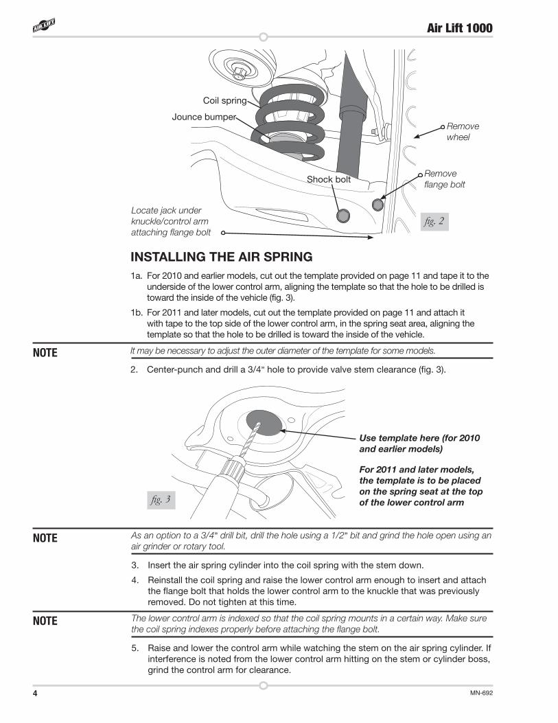
INSTALLING THE AIR SPRING1a. For 2010 and earlier models, cut out the template provided on page 11 and tape it to the
underside of the lower control arm, aligning the template so that the hole to be drilled is toward the inside of the vehicle (fig. 3).
1b. For 2011 and later models, cut out the template provided on page 11 and attach it with tape to the top side of the lower control arm, in the spring seat area, aligning the template so that the hole to be drilled is toward the inside of the vehicle.
It may be necessary to adjust the outer diameter of the template for some models.
2. Center-punch and drill a 3/4” hole to provide valve stem clearance (fig. 3).
As an option to a 3/4” drill bit, drill the hole using a 1/2” bit and grind the hole open using an air grinder or rotary tool.
3. Insert the air spring cylinder into the coil spring with the stem down.
4. Reinstall the coil spring and raise the lower control arm enough to insert and attach the flange bolt that holds the lower control arm to the knuckle that was previously removed. Do not tighten at this time.
The lower control arm is indexed so that the coil spring mounts in a certain way. Make sure the coil spring indexes properly before attaching the flange bolt.
5. Raise and lower the control arm while watching the stem on the air spring cylinder. If interference is noted from the lower control arm hitting on the stem or cylinder boss, grind the control arm for clearance.
NOTE
NOTE
NOTE
fig. 3
fig. 2
Coil spring
Jounce bumper
Shock bolt
Locate jack under knuckle/control arm attaching flange bolt
Remove wheel
Remove flange bolt
For 2011 and later models, the template is to be placed on the spring seat at the top of the lower control arm
Use template here (for 2010 and earlier models)
5MN-692
Air Lift 1000
INSTALLING THE AIR LINEA tee air line installation is recommended. If the weight in the vehicle varies from one side to the other and unequal pressures are needed to level the load or compensate for axle torque transfer in racing applications, use dual air lines (see page 7).
TEE AIR LINE ROUTINGTO PREVENT THE AIR LINE FROM MELTING, MAINTAIN AT LEAST 8” (203MM) FROM THE EXHAUST SYSTEM TO THE AIR LINE.
1. Locate the desired tee location on the frame rail or cross member. Determine and cut an adequate length of air line to reach from the tee to the left and right side air springs.
LEAVE SUFFICIENT AIR LINE SLACK TO PREVENT ANY STRAIN ON THE FITTING DURING AXLE MOTIONS.
2. Slide an air line clamp onto the air line.
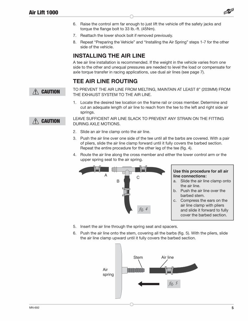
3. Push the air line over one side of the tee until all the barbs are covered. With a pair of pliers, slide the air line clamp forward until it fully covers the barbed section. Repeat the entire procedure for the other leg of the tee (fig. 4).
4. Route the air line along the cross member and either the lower control arm or the upper spring seat to the air spring.
AB
CUse this procedure for all air line connections:a. Slide the air line clamp onto
the air line.b. Push the air line over the
barbed stem.c. Compress the ears on the
air line clamp with pliers and slide it forward to fully cover the barbed section.
fig. 4
6. Raise the control arm far enough to just lift the vehicle off the safety jacks and torque the flange bolt to 33 lb.-ft. (45Nm).
7. Reattach the lower shock bolt if removed previously.
8. Repeat “Preparing the Vehicle” and “Installing the Air Spring” steps 1-7 for the other side of the vehicle.
5. Insert the air line through the spring seat and spacers.
6. Push the air line onto the stem, covering all the barbs (fig. 5). With the pliers, slide the air line clamp upward until it fully covers the barbed section.
fig. 5
Stem Air line
Air spring
CAUTION
CAUTION
6 MN-692
Air Lift 1000
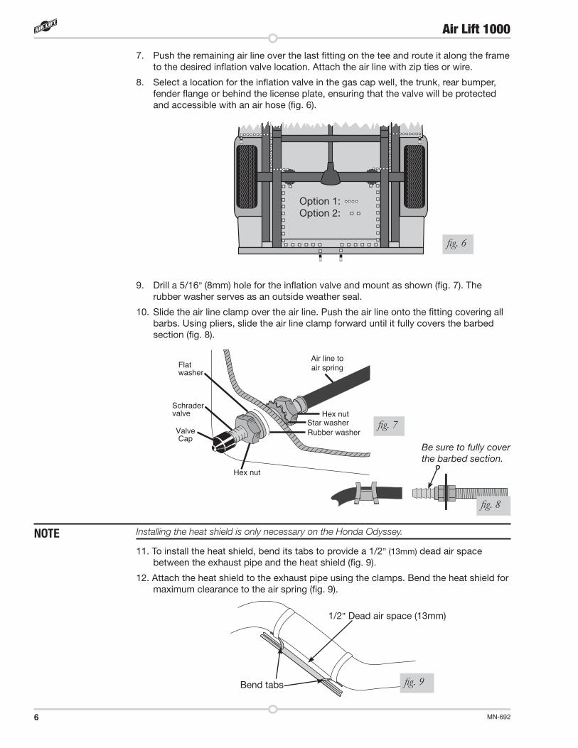
Installing the heat shield is only necessary on the Honda Odyssey.
11. To install the heat shield, bend its tabs to provide a 1/2” (13mm) dead air space between the exhaust pipe and the heat shield (fig. 9).
12. Attach the heat shield to the exhaust pipe using the clamps. Bend the heat shield for maximum clearance to the air spring (fig. 9).
9. Drill a 5/16” (8mm) hole for the inflation valve and mount as shown (fig. 7). The rubber washer serves as an outside weather seal.
10. Slide the air line clamp over the air line. Push the air line onto the fitting covering all barbs. Using pliers, slide the air line clamp forward until it fully covers the barbed section (fig. 8).
fig. 8
7. Push the remaining air line over the last fitting on the tee and route it along the frame to the desired inflation valve location. Attach the air line with zip ties or wire.
8. Select a location for the inflation valve in the gas cap well, the trunk, rear bumper, fender flange or behind the license plate, ensuring that the valve will be protected and accessible with an air hose (fig. 6).
Bend tabs
1/2” Dead air space (13mm)
NOTE
fig. 9
Air line toair spring
Hex nut
Hex nut
ValveCap
Schrader valve
Star washerRubber washer
Flatwasher
Option 1:Option 2:
fig. 6
Be sure to fully cover the barbed section.
fig. 7

7MN-692
Air Lift 1000
13. Raise the axle or lower the vehicle body until the air springs lightly touch the upper spring seat and lower spacers.
14. Check the exhaust clearance and ensure that it is at least 2-3 inches (51-76mm) from the air spring. If necessary, loosen the clamps and rotate or move to obtain additional clearance. Reattach the shock absorbers if removed earlier in the installation.
DO NOT INFLATE AIR SPRINGS BEFORE READING THE MAINTENANCE AND OPERATION SECTION.
15. Continue to “Completing the Installation.”
DUAL AIR LINE ROUTINGTO PREVENT AIR LINE FROM MELTING, KEEP IT AT LEAST 8” (203MM) FROM EXHAUST SYSTEM.
1. Select a location for the inflation valves in the rocker panel flange, or rear bumper, assuring that each valve will be protected and accessible with an air hose.
2. Determine and cut an adequate length of air line to reach from the valve location to the left side air spring.
LEAVE SUFFICIENT AIR LINE SLACK TO PREVENT ANY STRAIN ON FITTING DURING AXLE MOTIONS.
3. Insert the air line through the spring seat and spacer.
4. Slide the air clamp onto the cut air line.
5. Push the air line onto the stem, covering all the barbed section (see fig. 5). With pliers slide the air line clamp forward until it fully covers the barbed section.
6. Repeat process for the right side.
7. Drill a 5/16” (8mm) hole for the inflating valves and mount as illustrated. The rubber washer is for an outside weather seal (see fig. 7).
8. Route the air line along the control arm and frame to the inflation valve location and cut off the excess.
9. Slide a clamp onto the air line and push the air line over the fitting, covering all the barbs. With pliers slide the air line clamp forward until it fully covers the barbed section (see fig. 8).
10. Raise the axle or lower body until the air springs lightly touch the upper spring seat and lower spacers.
11. Check the exhaust clearance and ensure that it is at least 2-3 inches (51-76mm) from the air springs. If necessary, loosen the clamps and rotate or move to obtain additional clearance. If you are installing this kit on a Honda Odyssey, see page 6 for instruction on how to install the heat shield. Reattach the shock absorbers if removed earlier in the installation.
COMPLETING THE INSTALLATION1. Inflate the air springs to 35 PSI (2.4BAR). Test for air leaks by applying a soapy water
solution to all valve cores, fittings and connections.
2. Lower the vehicle to the ground. Read “Maintenance and Servicing” for proper care of the air springs.
3. Recheck air pressure after 24 hours. A 2-4 PSI (.14-.28BAR) loss after initial installation is normal. If pressure has dropped more than 5 PSI(.34BAR), retest for leaks.
CAUTION
CAUTION
CAUTION

8 MN-692
Air Lift 1000
Minimum Air Pressure Maximum Air Pressure5 PSI ( .34BAR) 35 PSI (2 .4BAR)
FAILURE TO MAINTAIN CORRECT MINIMUM PRESSURE (OR PRESSURE PROPORTIONAL TO LOAD), BOTTOMING OUT, OVER-EXTENSION OR RUBBING
AGAINST ANOTHER COMPONENT WILL VOID THE WARRANTY.
Maintenance and Servicing
MAINTENANCE GUIDELINESBy following these steps, vehicle owners will obtain the longest life and best results from their air springs.
1. Check the air pressure weekly.
2. Always maintain at least the recommended minimum air pressure to prevent the air spring from being pinched. Never inflate beyond the maximum air pressure.
3. If the system develops a slow air leak, use a solution of liquid dish soap and water to check all air line connections and the inflation valve core before deflating and removing the air spring.
4. Always add air to springs in small quantities, checking the pressure frequently. Sleeves require less air volume than a tire and inflate quickly.
OPERATING TIPS1. Inflate the air springs to 35 PSI (2.4BAR) before adding the payload. This will allow
the air cylinder to properly mesh with the coil spring. After the vehicle is loaded, adjust your air pressure down to level the vehicle and for ride comfort.
2. When carrying a payload it will be helpful to increase the tire inflation pressure in proportion to any overload condition. Air Lift recommends a 2 PSI (.14BAR) increase above normal for each 100 pounds additional load on the axle.
DO NOT EXCEED THE VEHICLE MANUFACTURERS’ MAXIMUM GROSS VECHICLE WEIGHT RATING.CAUTION

9MN-692
Air Lift 1000
Product UseFREQUENTLY ASKED QUESTIONSQ. Will installing air springs increase the weight ratings of a vehicle?
No. Adding air springs will not change the weight ratings (GAWR, GCWR and/or GVWR) of a vehicle. Exceeding the GWVR is dangerous and voids the Air Lift warranty.
Q. Is it necessary to keep air in the air springs at all times and how much pressure will they need?
The minimum air pressure should be maintained at all times. The minimum air pressure keeps the air spring in shape, ensuring that it will move throughout its travel without rubbing or wearing on itself.
Q. Is it necessary to add a compressor system to the air springs?
No. Air pressure can be adjusted with any type of compressor as long as it can produce sufficient pressure to service the springs. Even a bicycle tire pump can be used, but it’s a lot of work.
Q. How long should air springs last?
If the air springs are properly installed and maintained they can last indefinitely.
Q. Will raising the vehicle on a hoist for service work damage the air springs?
No. The vehicle can be lifted on a hoist for short-term service work such as tire rotation or oil changes. However, if the vehicle will be on the hoist for a prolonged period of time, support the axle with jack stands in order to take the tension off of the air springs.
TUNING THE AIR PRESSUREPressure determination comes down to three things — level vehicle, ride comfort, and stability.
1. Level vehicle
If the vehicle’s headlights are shining into the trees or the vehicle is leaning to one side, then it is not level (fig. 10). Raise the air pressure to correct either of these problems and level the vehicle.
2. Ride comfort
If the vehicle has a rough or harsh ride it may be due to either too much pressure or not enough (fig. 11). Try different pressures to determine the best ride comfort.
3. Stability
Stability translates into safety and should be the priority, meaning the driver may need to sacrifice a perfectly level and comfortable ride. Stability issues include roll control, bounce, dive during braking and sponginess (fig. 12). Tuning out these problems usually requires an increase in pressure.
fig. 10 fig. 11Bad headlight aim Rough ride
Sway and body roll
fig. 12
10 MN-692
Air Lift 1000
GUIDELINES FOR ADDING AIR1. Start with the vehicle level or slightly above.
2. When in doubt, always add air.
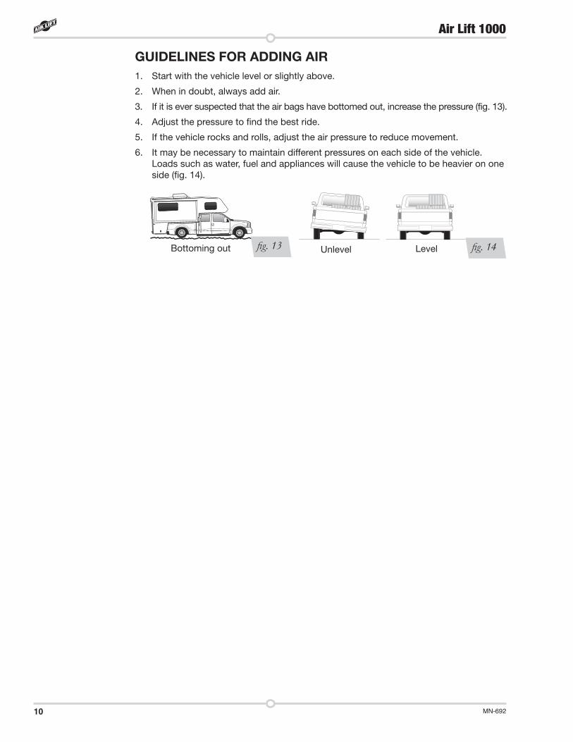
3. If it is ever suspected that the air bags have bottomed out, increase the pressure (fig. 13).
4. Adjust the pressure to find the best ride.
5. If the vehicle rocks and rolls, adjust the air pressure to reduce movement.
6. It may be necessary to maintain different pressures on each side of the vehicle. Loads such as water, fuel and appliances will cause the vehicle to be heavier on one side (fig. 14).
fig. 13 fig. 14Bottoming out Unlevel Level
11MN-692
Air Lift 1000
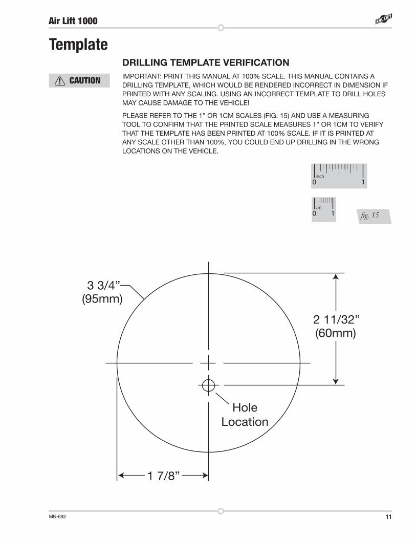
3 3/4”
1 7/8”
HoleLocation
'99 - '00 Honda OdysseyTemplate
(95mm)
2 11/32”(60mm)
(48mm)
TemplateDRILLING TEMPLATE VERIFICATIONIMPORTANT: PRINT THIS MANUAL AT 100% SCALE. THIS MANUAL CONTAINS A DRILLING TEMPLATE, WHICH WOULD BE RENDERED INCORRECT IN DIMENSION IF PRINTED WITH ANY SCALING. USING AN INCORRECT TEMPLATE TO DRILL HOLES MAY CAUSE DAMAGE TO THE VEHICLE!
PLEASE REFER TO THE 1” OR 1CM SCALES (FIG. 15) AND USE A MEASURING TOOL TO CONFIRM THAT THE PRINTED SCALE MEASURES 1” OR 1CM TO VERIFY THAT THE TEMPLATE HAS BEEN PRINTED AT 100% SCALE. IF IT IS PRINTED AT ANY SCALE OTHER THAN 100%, YOU COULD END UP DRILLING IN THE WRONG LOCATIONS ON THE VEHICLE.
fig. 15
inch0 1
cm0 1
CAUTION

13MN-692
Air Lift 1000
Replacement Part InformationIf replacement parts are needed, contact the local dealer or call Air Lift customer service at (800) 248-0892. Most parts are immediately available and can be shipped the same day.
Contact Air Lift Company customer service at (800) 248-0892 first if:• Parts are missing from the kit.• Need technical assistance on installation or operation.• Broken or defective parts in the kit.• Wrong parts in the kit.• Have a warranty claim or question.
Contact the retailer where the kit was purchased:• If it is necessary to return or exchange the kit for any reason.• If there is a problem with shipping if shipped from the retailer.• If there is a problem with the price.
Contact InformationMailing address P.O. Box 80167 Lansing, MI 48908-0167
Shipping address 2727 Snow Road for returns Lansing, MI 48917
Phone Toll free: (800) 248-0892 International: (517) 322-2144
Email [email protected]
Web address www.airliftcompany.com
Limited Warranty and Return PolicyAir Lift Company provides a limited lifetime warranty to the original purchaser of its Load Support products, that the products will be free from defects in workmanship and materials when used on cars and trucks as specified by Air Lift Company and under normal operating conditions, subject to the requirements and exclusions set forth in the full Limited Warranty and Return Policy that is available online at www.airliftcompany.com/warranty.
For additional warranty information contact Air Lift Company customer service.

Air Lift Company • 2727 Snow Road • Lansing, MI 48917 or P.O. Box 80167 • Lansing, MI 48908-0167 Toll Free (800) 248-0892 • Local (517) 322-2144 • Fax (517) 322-0240 • www.airliftcompany.com
Thank you for purchasing Air Lift products — the professional installer’s choice!
Need Help?Contact Air Lift Company customer service department by calling (800) 248-0892. For calls from outside the USA or Canada, dial (517) 322-2144.
Printed in the USA JJC-0118