dwpf air lift pump life cycle evaluation
TRANSCRIPT
WSRC-TR-2003-00426 Revision 0
DWPF AIR LIFT PUMP LIFE CYCLE EVALUATION (U)
KENNETH J. IMRICH
MICHAEL E. SMITH
AND
DENNIS F. BICKFORD
SAVANNAH RIVER TECHNOLOGY CENTER
Publication Date: February 2, 2004
Westinghouse Savannah River Company Savannah River Site
Aiken, SC 29808
PREPARED FOR THE U.S. DEPARTMENT OF ENERGY UNDER CONTRACT DE-AC09-96SR18500

This document was prepared in conjunction with work accomplished under Contract No.DE-AC09-96SR18500 with the U. S. Department of Energy.
DISCLAIMER
This report was prepared as an account of work sponsored by an agency of the United StatesGovernment. Neither the United States Government nor any agency thereof, nor any of theiremployees, makes any warranty, express or implied, or assumes any legal liability or responsibilityfor the accuracy, completeness, or usefulness of any information, apparatus, product or processdisclosed, or represents that its use would not infringe privately owned rights. Reference herein toany specific commercial product, process or service by trade name, trademark, manufacturer, orotherwise does not necessarily constitute or imply its endorsement, recommendation, or favoring bythe United States Government or any agency thereof. The views and opinions of authors expressedherein do not necessarily state or reflect those of the United States Government or any agencythereof.
This report has been reproduced directly from the best available copy.
Available for sale to the public, in paper, from: U.S. Department of Commerce, National TechnicalInformation Service, 5285 Port Royal Road, Springfield, VA 22161,phone: (800) 553-6847,fax: (703) 605-6900email: [email protected] ordering: http://www.ntis.gov/help/index.asp
Available electronically at http://www.osti.gov/bridgeAvailable for a processing fee to U.S. Department of Energy and its contractors, in paper, from: U.S.Department of Energy, Office of Scientific and Technical Information, P.O. Box 62, Oak Ridge, TN37831-0062,phone: (865)576-8401,fax: (865)576-5728email: [email protected]

WSRC-TR-2003-00426 Revision 0
SMT STRATEGIC MATERIALS TECHNOLOGY
Keywords: DWPF Melter BLD-210-S Corrosion Retention: 25 Years
DWPF Air Lift Pump Life Cycle Evaluation (U)
Kenneth J. Imrich
Michael E. Smith
and
Dennis F. Bickford
Issued:
February 2, 2004
Patent Status: This internal management report is being transmitted without DOE patent clearance, and no further dissemination or publication shall be made of the report without prior approval of the DOE-SR patent counsel. SRTC SAVANNAH RIVER TECHNOLOGY CENTER, AIKEN, SC 29808 Westinghouse Savannah River Company Prepared For The U.S. Department Of Energy Under Contract DE-AC09-96SR18500

TABLE OF CONTENTS
1.0 SUMMARY..........................................................................................................................1
2.0 BACKGROUND..................................................................................................................1
3.0 TEST DETAILS ..................................................................................................................2
4.0 NONDESTRUCTIVE AND DESTRUCTIVE EXAMINATIONS.................................4
5.0 DISCUSSION.....................................................................................................................12
6.0 CONCLUSIONS................................................................................................................14
7.0 RECOMMENDATIONS ..................................................................................................15
8.0 PATH FORWARD............................................................................................................16
9.0 ACKNOWLEDGMENTS.................................................................................................16
10.0 REFERENCES ..................................................................................................................16

LIST OF FIGURES
Figure 1 Air Lift Pump Mockup in DWPF Pour Spout Test Stand. ........................................2
Figure 2 EES Drawing, DWPT Melter Air Lift Test Mock Assembly And Details (EES–22863-MO-002 Rev. A). ...........................................................................................3
Figure 3 Photographs of the airlift pump after testing.............................................................6
Figure 4 Photographs showing sectioning of the lower half of the pump. ..............................6
Figure 5 Analysis of deposit at inlet of the platinum nozzle. ..................................................7
Figure 6 Photographs of Pt nozzle and Inconel 690 housing. .................................................7
Figure 7 SEM photographs of mating Inconel 690 and Platinum threads and corresponding EDS spectra for the various regions. .........................................................................8
Figure 8 Photomicrograph of the platinum nozzle. .................................................................9
Figure 9 SEM photographs showing location of EDS spectra of glass taken from within a crack at mid-wall between the threads and air passage of the nozzle. ....................10
Figure 10 SEM photograph showing the air passage of the nozzle and a EDS spectra of the solidified glass... ................................................................................................10
Figure 11 SEM photograph showing the mouth of a crack located on the inner diameter of the nozzle. EDS spectra from spot 6 shows a phase that is enriched in iron...........................................................................................................................11
Figure 12 Optical micrographs of the Inconel 690 pump........................................................11

Page 1 of 16 WSRC-TR-2003-00426 Rev. 0
DWPF Air Lift Pump Life Cycle Evaluation (U)
1.0 SUMMARY
The Defense Waste Processing Facility (DWPF) air lift pump was successfully tested at Clemson for 72 days of operation. It provided sufficient flow to pump molten glass without excessive foaming. Slurry feeding also did not reveal any problems with cold cap stability. Metallurgically the Inconel 690 (690) portions of the pump were in excellent condition with no visual evidence of degradation even in high flow regions, i.e., air/melt interface and glass discharge regions. Spinel deposits, which completely covered the air passage on one side, were found at the inlet of each platinum/rhodium (Pt/Rh) nozzle. Although the deposits were extensive, they were porous and did not have an adverse effect on the operation of the pump. The technique used to secure the platinum/rhodium nozzles to the 690 housing appeared to be adequate with only minor oxidation of the 690 threads and glass in-leakage. Galvanic attack was observed where the nozzle formed a seal with the 690. Significant pitting of the 690 was observed around the entire seal. Intergranular cracking of the Pt/Rh alloy was extensive but the cause could not be determined. Testing would be required to evaluate the degradation.
Data from the performance test and the metallurgical evaluation are being used to modify the design of the first DWPF production air lift pump. It will be fabricated entirely from 690 and use argon as the purge gas. It is intended to have a service life of 6 months. Recommendations for insertion, operation, and inspection of the pump are also included in this report. Performance data collected from the operation of the production pump will be used to further optimize the design. Laboratory exposure tests should also be performed to evaluate the galvanic effect between platinum/rhodium and 690.
2.0 BACKGROUND
A DOE Tank Focus Area program to assess possible means of increasing the Defense Waste Processing Facility (DWPF) Melter melt rate was initiated in FY01. A lumped parameter comparison of DWPF data with earlier pilot plant scale data indicated that melt capacity for a given feed was limited by overheating of the glass immediately under the reacting feed (cold cap). Pumps were considered as a means of increasing glass circulation and opening a vent hole in the cold cap to allow increased electrode power, and thus increased melter total power. Limited locations for a pump in the DWPF melter top head, and glass pumping limitations of traditional pumps lead to the development of a new system utilizing air lift pumping.
The air lift concept was tested with glycerin and an Inconel proof-of-principle air lift was tested in molten glass and found to be an effective pump. In addition, small scale air lift pumps were tested in the Slurry Fed Melt Rate Furnace (SMRF) to evaluate the overall behavior of the cold cap with an air lift pump. Details of these tests and others are given elsewhere (Ref. 1). Prior experience with traditional pumps in glass, and evaluation of this performance with the lumped parameter heat transfer model has indicated that melt rate increases are possible from a single air lift pump unit (Ref.1).
Due to the success of these tests and modeling work, a full-scale Inconel unit was fabricated and installed in a glass hold tank at the Clemson Environmental Technologies Laboratory (CETL) facility on September 30, 2002. The main purpose of this test was to evaluate the expected unit
Page 2 of 16 WSRC-TR-2003-00426 Rev. 0
life. To the extent possible, the test was performed to also provide information on air lift design details and foam collapse rate. Design details of glass discharge height and nozzle design were also tested, as they require full scale testing in molten glass. This pump was designed to operate with a gas flow rate up to 30 scfh. In addition, it was used to provide initial indications of the interactions with the cold cap during a one day slurry feeding test near the end of the test (Ref. 2). Due to problems with the initial glass hold tank (glass foam buildup due to small glass hold tank diameter and heater failures), a new test stand was built and testing finally completed in August 2003. A total of 72 days of operation (non-slurry feeding except for one day) were completed before the pump was removed. Most of the test time (48 days) was in the new test stand.
Anticipated benefits to DWPF of the air lift pump are:
• Enhanced melt rate from direct action of increased overall glass circulation rates improving transfer of electrode power to the bottom of the cold cap. This may be the result of increased overall glass velocity or improved venting of cold cap gases trapped under the cold cap. This is the mode of melt rate improvement of traditional pumps operated with modest gas flow rates. However in the present case, the efficiency of the pumping action is improved, so that lower gas flows are required, and the gas is not forced to accumulate under the cold cap. (Gas bubbles generated by the melting process still have to vent out of the cold cap.)
• Additional increases to melt rates from enhanced power available to the cold cap and slurry indirectly by heat transfer from the pumped glass to the melter plenum. It increases total power available to the melter by allowing additional electrode power to be applied without overheating of the glass under the cold cap.
• More uniform glass pool temperatures, making it easier to stay within temperature operating limits at the top and bottom of the glass pool.
• Evaluation of the heat transfer across the surface of the glass in DWPF suggests that a barrier layer may be forming. The pumping action of the hot glass from an air lift may push aside or raise the temperature of viscous layers or un-dissolved material floating on top of the glass pool, causing them to dissolve or dissipate.
Melt Line
Bubbler
Melter Pot
Heaters43”
This report discusses the full scale air lift pump tests at the CETL. This includes the non-destructive and destructive evaluations (NDE and DE) performed on the pump after the test. The one day slurry feeding test has been described in a separate DWPF inter-office memorandum (Ref. 2).
3.0 TEST DETAILS
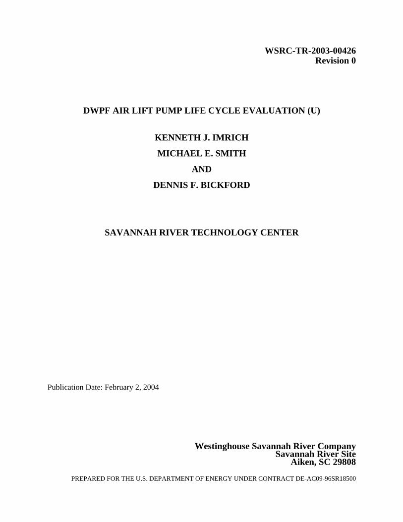
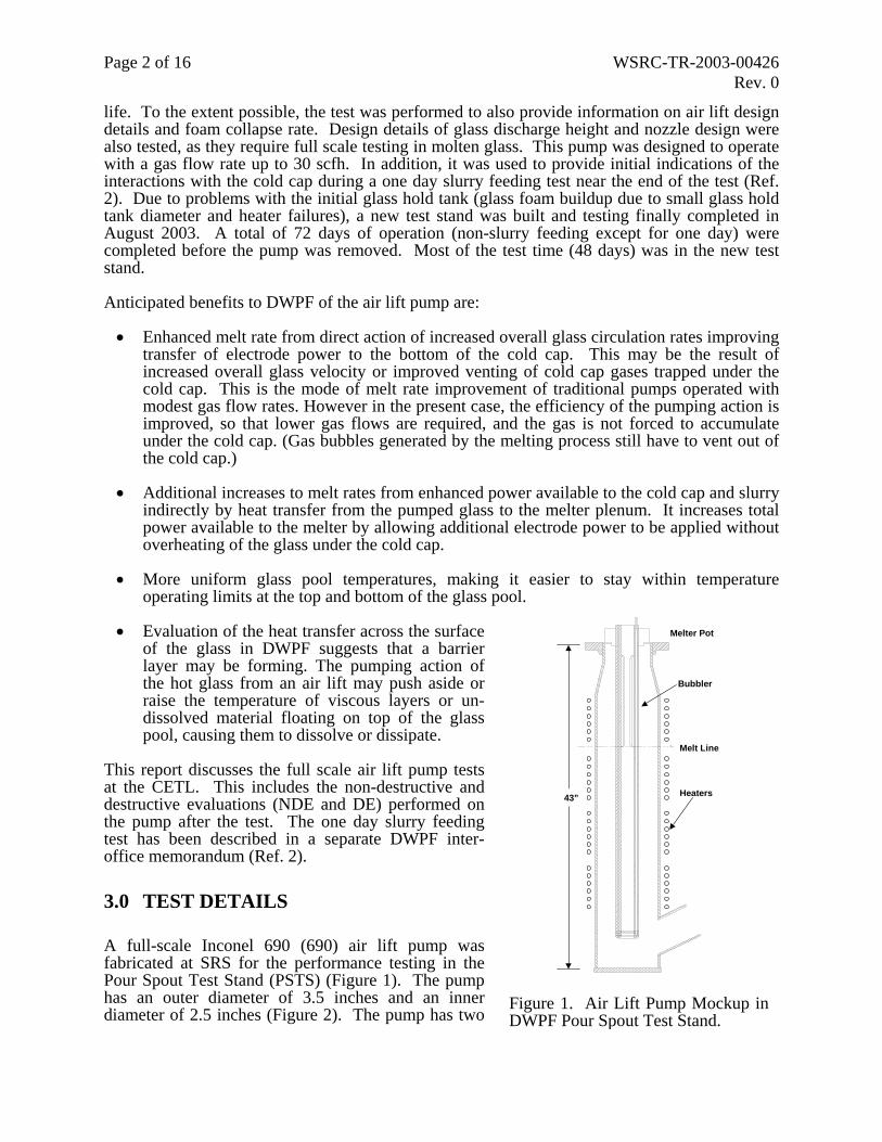
A full-scale Inconel 690 (690) air lift pump was fabricated at SRS for the performance testing in the Pour Spout Test Stand (PSTS) (Figure 1). The pump has an outer diameter of 3.5 inches and an inner diameter of 2.5 inches (Figure 2). The pump has two
Figure 1. Air Lift Pump Mockup in DWPF Pour Spout Test Stand.
Page 3 of 16 WSRC-TR-2003-00426 Rev. 0
p s iPr(db
T1cztsfhlt
Afo
latinum nozzles that can be either run together or just one at a time. A thermocouple wa
Figure 2. EES Drawing, DWPT Melter Air Lift Test Mock Assembly And Details (EES–22863-MO-002 Rev. A).
nstalled in the pump to monitor glass temperature as well. The initial plan was to place it in the STS with simulated DWPF glass and then run it (without slurry feeding) for several months. A un plan entitled “Run Plan for the Full-Scale Air Lift Bubbler Life Cycle Test at the CETL U)”, SRT-GPD-2002-00123 was initially used. CETL personnel were responsible for using aily log sheets to monitor the test. An air flow of 20 scfh was targeted for one nozzle at the eginning of the test. The PSTS reservoir has an inner diameter of about 8 inches.
he pump was installed in the PSTS on 9/30/02. The glass temperature was maintained above 100°C as indicated by the pump thermocouple. Due to excessive glass foaming that was oming over the top of the PSTS reservoir and threatening to damage the PSTS heaters (10 ones), the pump was removed on 10/11/02 and work began on extending the PSTS to prevent his glass from foaming out of the PSTS. The PSTS was restarted with the extension as well as a olenoid timer on the air supply line that shut off the air flow one hour per day to minimize glass oaming over the top. The pump was installed on 11/20/02, but on 11/26/02 the PSTS Zone 3 eater failed and the pump was again removed to repair the PSTS. During this testing period ower than desired air flow rates were being achieved but the flow was slowly increasing over ime (3 scfh on 11/20/02, 8 scfh on 11/21/02, and then up to 10 scfh on 11/22/02).
subsequent attempted restart of the PSTS on 1/6/03 showed that PSTS Zones 5 and 6 had ailed sometime after the PSTS had been shutdown on 11/26/03. At this time the pump had been perated for approximately 18 days.

Page 4 of 16 WSRC-TR-2003-00426 Rev. 0
On 3/13/03 the pump was reinstalled in the rebuilt PSTS. Maximum airflow was only 5 scfh but was up to 10 scfh on 3/17/03, 15 scfh on 3/18/03, and finally 20 scfh on 3/19/03. Unfortunately the PSTS Zone 1 heater failed on 3/19/03 and test pump had to be removed.
The PSTS was used because it was the only available piece of equipment that had a sufficient molten glass depth for the pump test. The main DWPF technical contact and the test lead agreed after the 3/19/03 failure that the PSTS was not adequate for the test and thus it was not used anymore. The main reasons for the decision were 1) rebuilds of the PSTS took a long time, 2) the heaters were not robust enough and further heater failures were expected, and 3) a larger diameter melt pool and more uniform/higher glass temperature was desired as well to prevent excessive foam buildup. The remaining funding for the CETL support of the test was insufficient to buy new parts for a new test stand. Dan Iverson (DWPF technical contact) designed a simple new test stand that could use parts and materials that were already available either at SRS or the CETL. A 15” inner diameter Inconel pot was fabricated at SRS. The pot was shipped to the CETL where the new test stand was put together. A new test plan was written, “Revised Run Plan for the Full-Scale Air Lift Bubbler Life Cycle Test at the CETL (U)”, SRT-GPD-2003-00061, to reflect the use of the new test stand.
The new test stand was charged with DWPF black startup frit and heated to an operational temperature of about 1120 °C. The pump was installed the next day on 7/9/03. Unlike before, both nozzles were operated at 10 scfh flow per nozzle. These flow rates remained fairly constant for the rest of the test. Glass temperature, as indicated by the pump thermocouple, was maintained at about 1120 °C for the duration of the test. No foaming buildup was observed and therefore the theory that the previous foamy buildup problems with the PSTS were due to the small PSTS inner diameter and temperature gradient which allowed the foam to “climb up” the PSTS reservoir wall was confirmed. Throughout the duration of the test with the new test stand, CETL counted the number of bubbles heard for one minute each day. This number was in the range of 100 - 120 per minute. In addition, glass samples were taken weekly to determine if the glass composition was changing (alkalis being volatized). Subsequent analyses of these glass samples showed that the alkalis were not volatizing. Being a startup glass, the glass did not have corrosive components such as chlorides that may have attacked the Inconel pump at these elevated temperatures.
The pump was removed on 8/6/03 for a short visual inspection and then reinstalled. On 8/25/03 DWPF personnel performed a short term slurry feeding test that was videotaped. A mix of available simulated DWPF feeds was used for the tests and no problems were observed. On the next day (8/26/03), the pump was removed after running in the new test stand for 48 days. This gave a total of 72 days of operating time for the pump test. One of the air lines was disconnected prior to removing the pump from the molten glass. The second air line, which supplied air to the other nozzle, remained attached and functional until the pump was lifted out from the molten glass. The pump was brought back to SRTC for nondestructive and destructive evaluations by SRTC MTS personnel.
4.0 NONDESTRUCTIVE AND DESTRUCTIVE EXAMINATIONS
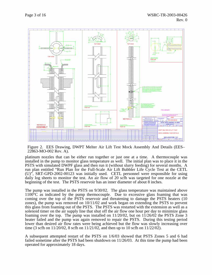
Visual examination of the 690 pump was performed and did not reveal any areas of significant degradation, i.e. corrosion or erosion. All edges appeared sharp and no material loss was noted in the high glass flow regions or at the melt air interface. Photographs of the pump are shown in
Figure 3. Ultrasonic thickness measurements were made at locations near those identified in the original report, but fabrication irregularities resulted in significant thickness variations from the original values. In addition, glass adhering to the inner diameter of the pump resulted in

Page 5 of 16 WSRC-TR-2003-00426 Rev. 0
scattering of the beam, which significantly affected the resolution of the thickness measurements. Because of these effects and the small amount of wall loss, a comparison of the initial and final UT thickness measurements could not be made. The entire inner diameter including the platinum nozzles were coated with a layer of glass. Although the nozzles were coated with glass the edges appeared to be sharp and the orifice showed no evidence of erosion.
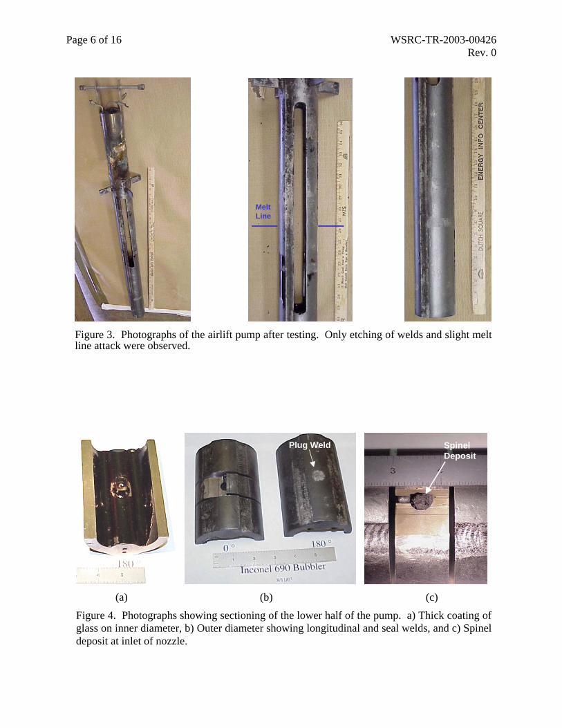
After completing the UT and visual examinations, the lower portion of the pump was cut off approximately 3 inches above the nozzles. This segment was then cut longitudinally between the nozzles (Figure 4). The halves were further sectioned approximately 0.5” above and below the nozzles exposing the air supply passage. The air supply on the side labeled 180 ° was completely blocked with glass. This probably resulted when the air supply from this side was cut off during removal from the molten glass. The other air supply passage from the side labeled 0 ° was free of any glass or other obstructions, i.e. oxide build up. Glass was fractured on the platinum nozzles using a vibra tool with light pressure. The pump segments containing the nozzles were then placed in boiling sodium hydroxide over the weekend to facilitate glass removal. Visual examination of the nozzles confirmed that no significant degradation had occurred. Shoulders used to screw the platinum nozzle into the 690 tube were distinct. Some minor roughening of the platinum had occurred.
The pump section containing the nozzles was further sectioned to expose the back, threaded end of the pump. Electro discharge machining (EDM) was used to precisely cut into the cavity behind the nozzle (Figure 4c). Machining revealed a significant lack of penetration around the circumference of the plug weld. Minimum wall thickness was approximately 0.0625”. Upon sectioning the side labeled 0° a large black deposit was observed covering the entire nozzle including the orifice. It sloped down from the top of the platinum nozzle to the back bottom edge of the cavity. The deposit was tightly adhering to both the platinum and 690 surfaces. A small portion of the deposit was chipped off and submitted for XRD analysis and was found to consist primarily of nickel iron oxide with minor amounts of chromium oxide and silica (Figure 5). The deposit was chipped away and the nozzle was cross-sectioned to expose the back of the nozzle (inlet) and the mating threads. Thread engagement between the platinum and 690 appeared tight at ambient conditions. Threads on the back of the nozzle were slightly deformed (compressed) indicating that the nozzle was peened securely into place after insertion into pump as required by the print. The back of the nozzle extended 0.25” into the cavity exposing approximately four threads. The outlet end of the nozzle was examined and did not indicate any measurable material loss. The orifice was not completely round but this may have resulted during the drilling or peening operations. Analysis of the platinum/rhodium (Pt/Rh) alloy using X-ray Fluorescence indicated that the alloy contained approximately 89 wt% Pt and 9 wt% Rh with trace amounts of Au and Zr. Iron was also detected but this was most likely from residual glass.
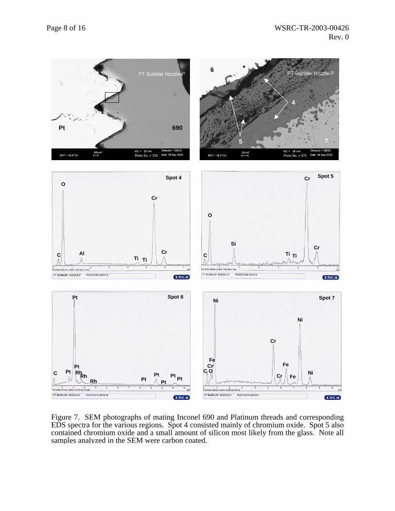
During metallographic preparation of the nozzle it became apparent that it had numerous cracks. Most were radially oriented between the threads to the air passageway but some were observed parallel to machined surfaces (Figure 6). Both the platinum and 690 threads showed evidence of degradation. A large pit was also observed in the 690 adjacent to glass sealing surface between the housing and the nozzle. This was observed on both nozzles. A thick chromium oxide layer had developed on the threads indicating that oxidation of the 690 had occurred (Figure 7). Glass was found in all of the radial cracks, however; it was depleted in iron. Small particles of chromium oxide were also found deep within the cracks. It most likely originated from oxidation of chromium in the 690 and was carried into the cracks by the molten glass. Microstructural examination revealed intergranular cracking of the platinum with cracks running generally in a
Page 6 of 16 WSRC-TR-2003-00426 Rev. 0
MeltLine
Figure 3. Photographs of the airlift pump after testing. Only etching of welds and slight melt line attack were observed.
Plug Weld
SpinelDeposit
(a) (b) (c) Figure 4. Photographs showing sectioning of the lower half of the pump. a) Thick coating of glass on inner diameter, b) Outer diameter showing longitudinal and seal welds, and c) Spinel deposit at inlet of nozzle.

Page 7 of 16 WSRC-TR-2003-00426 Rev. 0
1
2
[bubblerA1b .RAW] bubbler spinal Imrich74-2081> NiFe2O4 - Nickel Iron Oxide
85-0869> Eskolaite, syn - Cr2O339-1425> Cristobalite, syn - SiO2
0
500
1000
1500
Inte
nsity
(Cou
nts)
10 20 30 40 50 60 70Two-Theta (deg)
(a) (b)
Cr
O
Fe
Na
Ti
Ni
CrMn
Fe
FeNi
Ni
Spot 1
Spot 2
O
C
Na
Al Ca
Si
(c) (d) Figure 5. Analysis of deposit at inlet of the platinum nozzle. a) XRD spectrum of spineldeposit, b) SEM photograph of spinel deposit, c) EDS spectrum of spinel crystal, and d) EDSspectrum of a second phase in the deposit.
Pt
690
Pit690
Pt
690
PtPt
Air Flow
5 mm (a) (b) (c) Figure 6. Photographs of Pt nozzle and Inconel 690 housing. a) SEM photograph of pitadjacent to Pt nozzle, b) As-ground metallurgical specimen showing numerous radial cracks inthe platinum, and c) SEM photograph showing cracking parallel to machined surface (arrows).
Page 8 of 16 WSRC-TR-2003-00426 Rev. 0
690Pt
6
4
75
O
Cr
AlTi Ti
CrC
Spot 4
C
O
Si
Ti Ti
Cr
Cr
Spot 5
Pt
CRh
Pt
PtPtPt Pt PtRh
PtRh
Spot 6
CrC O
Cr
Cr Ni
Fe
Ni
Ni
Fe
Fe
Spot 7
Figure 7. SEM photographs of mating Inconel 690 and Platinum threads and correspondingEDS spectra for the various regions. Spot 4 consisted mainly of chromium oxide. Spot 5 also contained chromium oxide and a small amount of silicon most likely from the glass. Note all samples analyzed in the SEM were carbon coated.

Page 9 of 16 WSRC-TR-2003-00426 Rev. 0
radial orientation. Grain size varied dramatically with some grains exceeding several millimeters in length (Figure 8).
Investigation of the glass within the cracks using the EDS system on the SEM revealed that the glass was depleted in iron. Numerous locations were evaluated and yielded the same results. SEM photographs and EDS spectra of the glass from inside the crack and from inside the air passage are shown in Figures 9 and 10. The latter sample is consistent with the bulk glass chemistry. The composition of various phases located adjacent to the platinum in the air passage is shown in Figure 11. One of the phases contained mainly silicon and was significantly depleted in iron. The second phase contained a significant amount of iron and smaller amounts of nickel and chromium. This iron enriched phase, most likely a spinel, was only found adjacent to the platinum surface in the nozzle air passage.
The 690 segment containing the nozzle from the side labeled 180 ° was conventionally machined because the cavity and air passage was completely filled with glass. After the remaining glass was chipped away using the vibra tool a tightly adhering black deposit, similar to that found in the other nozzle, was observed surrounding the back side of the nozzle. The deposit did not appear to cover the orifice. There was a significant lack of penetration of the plug weld at the back of the nozzle. No further metallurgical evaluation of this nozzle was performed.
Metallurgical samples from the 690 portion of the pump were removed for optical metallography. One sample was cut from the outer diameter and included a portion of a longitudinal weld and the base material. A second sample was removed which included a cross-section through one of the air vertical passages. The samples were prepared by standard metallurgical techniques and eletrolyticly etched using a 10 % nital solution. Significant grain growth was observed in the base metal (Figure 12). Maximum depth of internal attack in both the weld fusion zone and the base metal was approximately 0.1 inch. The air passageway diameter was measured using a measuring microscope and averaged 0.195 inches (0.19 inches per the print) indicating a slight wall loss due to oxidation. Depth of internal oxidation around the air passageway was approximately 0.003 inches (Figure 12).
Figure 8. Photomicrograph of the platinum nozzle. Cracks can be seen following grain boundaries. Some grains were as large as several millimeters in length. Etch, aqua regia, 60°C 20 to 40 minutes.

Page 10 of 16 WSRC-TR-2003-00426 Rev. 0
Spot 5
C
O
Na
Al
Si
CaTiCa TiK
Spot 5
Figure 9. SEM photographs showing location of EDS spectra of glass taken from within a crack at mid-wall between the threads and air passage of the nozzle. Note absence of iron in glass composition from the crack.
PtGlass
Air Flow
1
C
O
Fe
FeNi Ni
Spot 1
AlNa
Si
Mn
NiMnTi TiCaK
Figure 10. SEM photograph showing the air passage of the nozzle and a EDS spectra of thesolidified glass. The glass is representative of the bulk chemistry and contains iron.
Page 11 of 16 WSRC-TR-2003-00426 Rev. 0
Figure 11. SEM photognozzle. EDS spectra fro
C
O
FeNi
AlMg
C
TiTi
Spot 6
Spot 7
PtGlass
(a)Figure 12. Optical micfor outer diameter of approximately 0.003 inc
raph showing the mouth of a crack located on the inner diameter of the m spot 6 shows a phase that is enriched in iron.
Spot 7
C
O
Ni NiCa
Fe
FeMn
MnTiTi Cr Cr
Al
CaNa
Si
Spot 6
Fe
Ni
Fe
Ni
Mn
Mn
r
Cr
(b) rographs of the Inconel 690 pump. a) Weld fusion zone and base metal the pump. b) Oxidation of the air passageway, depth of attack was hes.
Page 12 of 16 WSRC-TR-2003-00426 Rev. 0
5.0 DISCUSSION
Metallurgical Evaluation Results
Overall the air lift pump was in excellent condition after 72 days of successful operation. Visual and metallurgical evaluation did not reveal significant degradation, material loss or internal attack, of the 690 portion of the pump. Even regions in high flow areas around nozzles or at the glass discharge point at the air glass interface did not reveal any observable degradation. Minimal internal attack, internal void formation and depletion of chromium in the near surface regions due to oxidation, were observed in the air passage and glass contact regions. Degradation rate based on internal attack would predict a rate of approximately 0.5 inches per year, but movement of this interface would require material loss to occur. Material loss could not be estimated because significant local variations in wall thickness made comparison of UT readings impossible. The local thickness variations resulted from the various fabrication processes. Welds were examined and did not show any significant molten glass attack. Minimal degradation of the 690 may have resulted because the glass chemistry (DWPF start-up frit) was not very corrosive. In addition, the melter pot was fabricated entirely from 690. Due its large surface area compared to the pump, corrosion of this surface would be expected to have contributed significantly to the increase in Cr2O3 concentration in the glass (0.190 to 0.385 wt %). Therefore, the data obtained is not representative of what would be expected in DWPF. Degradation of the production pump should be carefully monitored during operation and a thorough metallurgical evaluation should be performed after it is removed from service.
The platinum nozzles were securely fastened into the pump by the use of threads and peening the back of the nozzles. This means of securing the platinum nozzles to the 690 housing appeared to be adequate. Some glass had seeped into the threads but this did not compromise the integrity of the joint. Increasing the area of the sealing surface on the nozzles should help minimize glass intrusion into the threads. There was also some oxidation of the 690 threads most likely resulting from air in leakage around the threads. Although there is a slight thermal expansion mismatch between platinum and 690, the volume increase associated with the oxide formation may have helped secure the nozzles in place at elevated temperatures.
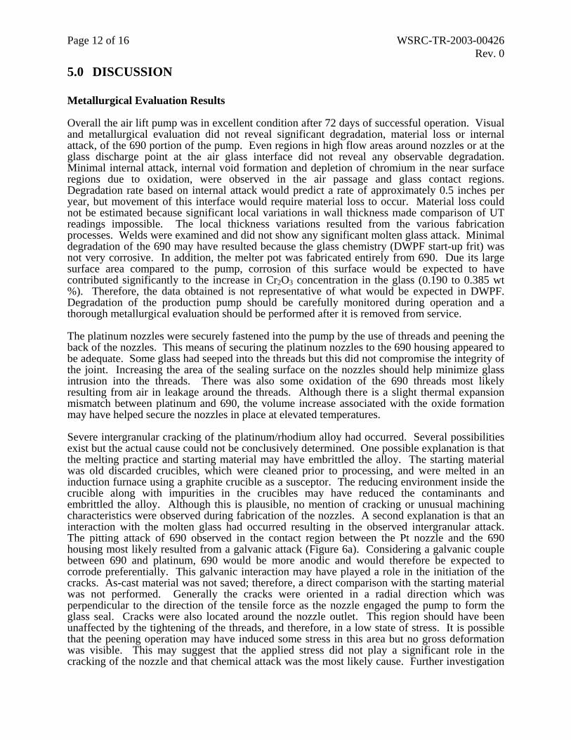
Severe intergranular cracking of the platinum/rhodium alloy had occurred. Several possibilities exist but the actual cause could not be conclusively determined. One possible explanation is that the melting practice and starting material may have embrittled the alloy. The starting material was old discarded crucibles, which were cleaned prior to processing, and were melted in an induction furnace using a graphite crucible as a susceptor. The reducing environment inside the crucible along with impurities in the crucibles may have reduced the contaminants and embrittled the alloy. Although this is plausible, no mention of cracking or unusual machining characteristics were observed during fabrication of the nozzles. A second explanation is that an interaction with the molten glass had occurred resulting in the observed intergranular attack. The pitting attack of 690 observed in the contact region between the Pt nozzle and the 690 housing most likely resulted from a galvanic attack (Figure 6a). Considering a galvanic couple between 690 and platinum, 690 would be more anodic and would therefore be expected to corrode preferentially. This galvanic interaction may have played a role in the initiation of the cracks. As-cast material was not saved; therefore, a direct comparison with the starting material was not performed. Generally the cracks were oriented in a radial direction which was perpendicular to the direction of the tensile force as the nozzle engaged the pump to form the glass seal. Cracks were also located around the nozzle outlet. This region should have been unaffected by the tightening of the threads, and therefore, in a low state of stress. It is possible that the peening operation may have induced some stress in this area but no gross deformation was visible. This may suggest that the applied stress did not play a significant role in the cracking of the nozzle and that chemical attack was the most likely cause. Further investigation

Page 13 of 16 WSRC-TR-2003-00426 Rev. 0
of Pt/Rh/690 galvanic couple would be necessary to determine and understand the degradation mechanism(s).
Spinel formation was noted at the inlet of each nozzle. The deposits were large enough to completely cover the air passage at the inlet of the nozzle. Although the deposits were extensive, they were porous and did not impede the air flow for the duration of the test. The propensity of the glass to form various spinel phases during the test at Clemson may have been increased because the melter pot was made entirely from 690. Even minimal corrosion of the 690 in this system may have increased the concentration of transition metals in the glass because of the large surface (690) to volume (glass) ratio. However, to minimize spinel formation during the operation of the DWPF production air lift pump, argon should be used rather than air to minimize oxidation of the 690 air passage. Disruptions in gas flow should also be avoided in order to minimize glass intrusion into the air passage. These operational controls should minimize the formation of spinel deposit and extend the life of the pump. The use of platinum or a platinum/rhodium alloy to line the air passage and as a nozzle should be further investigated in order to extend the operational life of the production pump.
During this evaluation the plug weld used to seal the cavity behind the nozzle on the outer diameter of the pump was found to have a significant lack of penetration. This was observed on both sides. The lack of penetration significantly reduced the corrosion allowance in this region. A through wall penetration of this weld would result in failure of the air lift pump, therefore, a different means of sealing these holes should be employed. A solid plug should be fabricated and secured into the hole using a full penetration weld to the depth of the plug. This should provide an adequate corrosion allowance in these regions.
DWPF Air Lift Pump Recommended Operation and Test Conditions
The air lift pump is a means of increasing overall circulation in the melter, and of transferring heat from the lower half of the melter to the level of the cold cap where the water must be boiled off and chemical reactions require heat for the glass fusion. To clearly establish the effects of the air lift it is necessary to have a baseline operation under steady operating conditions and well established melt rate and thermal profile. Cameras should be available to view and record the general appearance and coverage of the cold cap, with particular attention to warm vent holes and the pooling and spreading behavior of the aqueous feed.
The air lift might be designed and installed in such a way that the exiting glass flow is directed at the feed pile under the feed tubes. It should also be designed such that the flow can be directed at 90 degrees from feed piles, so that the full range of the effects of the pump on the stability of the cold cap and offgas surging can be tested.
The gas flow through the nozzles of the pump is expected to be optimum at about 0.5 scfm, but is strongly affected by the actual temperature and composition of glass being pumped. Thus, it is necessary to have control over about 0.1 to 2 scfm to establish the optimum.
The main diagnostic tools for the performance of the air lift pump are the average increase in glass production rate, the cold cap appearance as seen by the camera, and the temperature gradient in the glass near the air lift. In fact, the measurement of the thermal gradient is the most reliable method of monitoring the air lift operation. Thermocouples are dependable, and can be used in pairs to provide redundancy. To monitor the gradient, it is necessary to have a minimum of two thermocouples as low as practical in the pump and two at the average elevation of the cold cap in the air lift. At very low flow, sufficient to keep the air passages open, the air lift will not significantly affect the thermal gradient because the glass pumping rate will be low. As the pump is operated, the temperature at the cold cap level will approach that at the bottom inlet of the pump. The narrower the temperature difference between high and low elevations in the air

Page 14 of 16 WSRC-TR-2003-00426 Rev. 0
lift, the more effective the air lift is operating. As the air lift continues to operate at good pumping rates, the more uniform the entire melter temperature distribution will be, as will also be shown by the side thermowell.
The gas should be flowing through the pump at a moderate rate, if possible, as it is installed. This will help to keep the narrow passages free of glass that will reduce flow and might cause pluggage. The unit should be operated at low flow (about 0.2 scfm) initially to check for surging stability and low flow melt rate, after about a day at this level the gas flow can be incrementally increased about 0.1scfm per day of testing. If the melt rate at each stage is difficult to reliably monitor, then the increases in flow should be done more gradually.
As the flow is adjusted past the optimum pumping conditions, the melt rate will decrease as the bubbles start to form a channel. The thermocouples are necessary to avoid this condition. Once the optimum is found for a specific glass formulation, the gas flow should be kept as low as possible, consistent with the required melt rate, to minimize nozzle wear.
6.0 CONCLUSIONS
Based on the results of the Clemson testing and metallurgical evaluation of the air lift pump the conclusions are:
The air lift pump was successfully operated and provided sufficient flow to pump glass from the bottom of the melt pool without excessive glass foaming.
No problems were observed with the cold cap during the one day airlift pump slurry feeding test.
No significant degradation of the 690 was observed even in high flow regions and at air/melt interface.
Only minimal internal attack of the 690 was observed in areas contacted by the molten glass or in the air passages.
Apparent galvanic attack of the 690 occurred adjacent to the platinum/rhodium nozzles.
Significant degradation of the platinum nozzles was observed.
- Intergranular attack throughout the nozzles occurred but the cause could not be determined.
The technique used to secure the nozzles to pump (threaded joint and peening) were adequate for its length of service. If platinum nozzles are used in the future, the contact area between the platinum and 690 should be increased to minimize glass intrusion into the threads.
Significant spinel formation at the inlet of the nozzles was observed but because it was relatively porous it did not disrupt the flow of air through the nozzles.

Page 15 of 16 WSRC-TR-2003-00426 Rev. 0
7.0 RECOMMENDATIONS
The following recommendations are based on the conclusions from the air lift pump life cycle evaluation.
The first production DWPF air lift pump should be designed for a 6 month service life and be fabricated entirely from Inconel 690. Based on the performance of this air lift pump, further design modifications may be required for further improvement in operation of the DWPF melter.
Platinum or a platinum alloy should not be used on the production pump until the degradation mechanisms are fully understood. Immersion tests should be performed to evaluate the cause of the intergranular cracking, the extent of the galvanic potential between platinum and 690 under these conditions, and to optimize the design in order to increase performance and extend the pumps service life. The use of grain stabilized alloys should also be investigated.
Argon gas should be used with the Inconel 690 pump to minimize oxidation and possible spinel formation.
Recommendations for pump insertion, operation, and performance are as follows:
- Maintain steady state conditions inside melter for at least one day before pump insertion.
- If practical, maintain moderate gas flow rate during insertion into the melt pool.
- Direct glass flow from the pump toward the feed piles.
- Utilize similar feed compositions before and after pump insertion.
- Insert and operate borescopes during installation and normal operation of the pump.
- Optimize gas flow rate incrementally, and obtain melter steady state conditions before each flow rate change.
- Document critical melter data, i.e., pump thermal gradient, flow rate and pressure, offgas line pressure, side and vapor space thermowell temperature, cold cap appearance, and melt rate in order to objectively evaluate pump performance.
- If practical, rotate the pump 90 degrees and repeat test.
- Perform a visual inspection and a thorough metallurgical evaluation of the pump after it is removed from service.
- Perform laboratory molten glass immersion tests with platinum/rhodium and 690.

Page 16 of 16 WSRC-TR-2003-00426 Rev. 0
8.0 PATH FORWARD
The path forward involves the steps for the final design, fabrication, installation, and operation of an airlift pump in the DWPF melter.
The SRTC activities are as follows:
Provide final pump design input to DWPF Locate vendors with electron beam welding and gun drilling and verify capabilities Provide technical input to the pump risk assessment Support DWPF during initial usage of pump in DWPF melter
The main DWPF activities are as follows: Finalize risk assessment Finalize pump and jumper design Fabricate pump and jumper Install pump Monitor pump/melter behavior during initial usage of pump in DWPF melter
9.0 ACKNOWLEDGMENTS
The authors would like to express their appreciation to the following individuals for their commitment to this task, Kevin Kalbaugh (NDE Systems), Hector Guerrero (Engineering Development Lab), Rodney Merck and Lee Terry (CETL), and Dan Iverson (DWPF Process Cog Engineering).
10.0 REFERENCES
1) H. N. Guerrero and D. F. Bickford, DWPF Melter Air-Lift Bubbler: Development and Testing for Increasing Glass Melt Rates and Waste Dissolution (U), WSRC-TR-2002-00196, May 2002.
2) A. B. Barnes and D. C. Iverson, Evaluation of Air Lift Bubbler on Cold Cap While Slurry Feeding (U), CBU-WSE-2003-00157, September, 4, 2003.