kinetic modeling of energy separation process into a
TRANSCRIPT
Proceedings of ENCIT 2012 14th Brazilian Congress of Thermal Sciences and Engineering Copyright © 2012 by ABCM November 18-22, 2012, Rio de Janeiro, RJ, Brazil
KINETIC MODELING OF ENERGY SEPARATION PROCESS INTO A RANQUE-HILSCH VORTEX TUBE
George STANESCU, [email protected] Federal University of Paraná, Mechanical Engineering Department, 81531-990 Curitiba, PR, Brazil Abstract. Simultaneously producing heating and cooling, the Vortex tube is a simple, no moving components, small and lightweight, low cost, easy-to-operate and maintenance free device for gas expansion. In connection with the tremendous necessity for new ecological technologies, the aim of this paper is to present a new approach for understanding the Ranque-Hilsch Vortex Tube green refrigeration effect. Keywords: Ranque-Hilsch Vortex Tube, energy separation kinetic modeling, green refrigeration.
1. INTRODUCTION
The Ranque-Hilsch Vortex Tube (RHVT) is an interesting device to produce the refrigerating effect when a limited amount of cooling is required in special circumstances: a reliable small size equipment and freedom from electrical supplies. It has been described first in 1933 and then patented in 1934 by Georges Ranque a French scientist. Later, in 1946, a larger interest in this non-conventional method for producing cooling has been generated by a widely read article of Rudolph Hilsch.
RHVT is built by two concentric pipes of different diameters joined at one end. The two cylindrical chambers into the pipes are separated by a disk with a central orifice. The other end of the larger pipe is equipped with an outlet valve to control the gas stream discharge, while the gas stream flowing through the smaller pipe discharges freely into the atmosphere. Next to the junction and equally spaced around the larger pipe periphery are nozzles arranged to discharge tangentially into the cylinder. The core of the forced vortex, created into the tube when supplying compressed gas to the nozzles, is cold and is extracted from the end of smaller chamber. The periphery of the vortex is hot and is extracted from the end of the larger chamber, controlled by the valve.
Since it is a simple, compact and light device, and does not use refrigerants, during the last two decades, the need for less polluting technologies and more ecological technical solutions, generated a careful examination of the Vortex tube as an attractive alternative to improve the energy efficiency for some industrial applications (Stanescu et al., 1998, 2009, 2012), cooling equipment in NCM machines, non conventional refrigeration (Radcenco, 1990), etc.
Virtually any process using high-temperature or high-pressure gas may be a resource for energy recovery. Thus, in connection with the tremendous necessity for new ecological technologies, the aim of this paper is to present a new approach for understanding the Ranque-Hilsch Vortex Tube functioning for green refrigeration.
2. VORTEX TUBE PHYSICAL MODEL
A schematic view of the Vortex tube consists of two cylindrical chambers within pipes, contained between the inlet ports into nozzles and the outlet ports of pipes open to the surroundings as shown in Figs. 1 and 2. The outlet area of the larger pipe (the “hot end”) is controlled by a valve, while the outlet from the smaller pipe (the “cold end”) is free.
A forced vortex is created when supplying compressed air to the nozzles. Jets discharge into the larger cylindrical chamber at very high velocity generating a very high angular speed rotating gas column. Due to the viscous forces, the vortex rotates at constant angular velocity and its tangential velocity depends on the radius. Based on the conservation of the angular momentum of the gas leaving the nozzles, the angular momentum of the vortex core must have decreased by exactly the same amount as the angular momentum of the periphery has increased. The redistribution of angular momentum along radius is accompanied by the redistribution of the gas mass along the radius. Simultaneously, the rotational and translational kinetic energies are redistributed into the gas mass.
The two gas streams within the RHVT are throttled when passing through the orifice into the disk that separates the two cylindrical chambers, or through the hot end area controlled by the valve. These throttling occur such that the kinetic energies differently reenter the gas masses. This means that the two gas streams, each one a fraction of the total gas entering the Vortex tube, both at different temperatures smaller than the initial temperature of the compressed gas, will not regain exactly the energy they lost during redistribution. This makes possible that the average temperature of one gas stream (extracted from the “cold end”) is smaller than the initial temperature of the compressed gas, since the gas stream regains less energy than it lost. Obviously, the other gas stream (extracted from the “hot end”) is hotter than the compressed gas supplied to the Vortex tube, since now the gas regains more energy that it lost. The valve fitted in the “hot end” controls the proportions of the total gas flow which passes from the “hot end” and “cold end”.

Proceedings of ENCIT 2012 14th Brazilian Congress of Thermal Sciences and Engineering Copyright © 2012 by ABCM November 18-22, 2012, Rio de Janeiro, RJ, Brazil
Figure 1. Schematic lateral view of the Ranque-Hilsch Vortex Tube.
Figure 2. Schematic transversal view of the Ranque-Hilsch Vortex Tube. 3. MATHEMATICAL MODEL
Vortex tube has remained partly misunderstood until now. A number of theories have been developed to understand and explain the physical phenomena inside the Vortex tube (Rocha et al., 1997). The theory of D. C. Fulton (see the R433 Vortex Tube Refrigerator Technical Specification, P. A. Hilton Ltd., England, 1996.) relies on the conservation of angular momentum to explain the separation of the compressed gas entering the Vortex tube, into a cold gas stream and a hot one. Based on the First and Second Laws of Thermodynamics, Petrescu et. al. (1995) studied comparatively the Hilsch-Ranque Vortex tube expansion processes and the adiabatic reversible expansion performances. A comprehensive study of various aspects of Vortex tubes´ design has been presented by Radcenco (1990), through an exergy analysis.
This study focuses on a two-step kinetic mechanism of energy distribution inside the RHVT. Firstly, it is assumed that the air flow leaving the nozzles instantaneously evolves to a very high angular speed rotating air column inside the larger cylindrical chamber of diameter D. Then, during the second step, the central rotating air column of diameter d separates by itself into the smaller pipe by flowing through the orifice into the disk separating the two cylindrical chambers. Simultaneously, the remaining annular rotating column at the periphery leaves the Vortex tube flowing through the control valve at the larger pipe outlet (the “hot end”).
The mathematical problem consists of computing firstly the velocity, temperature and air pressure distribution throughout the rotating air column inside the cylindrical chamber and then to calculate the average temperature of the air extracted from the two Vortex tube exits. 3.1. First-step kinetic mechanism model
The first-step kinetic mechanism model considers the following hypotheses: • steady-state functioning of the Ranque-Hilsch Vortex Tube;

Proceedings of ENCIT 2012 14th Brazilian Congress of Thermal Sciences and Engineering Copyright © 2012 by ABCM November 18-22, 2012, Rio de Janeiro, RJ, Brazil
• compressible flow; • “chocked” reversible functioning of the convergent nozzles; • instantaneous thermodynamic equilibrium; • all processes occurring adiabatically; • negligible angular and radial velocities; • no gravity influence on the gas flow is considered; • compressed air entering the nozzles at ambient temperature T0; • ideal gas properties of the air; The mathematical model to study the first step processes derives from the following continuity and momentum
equations in connection with the first and the second laws of thermodynamics per-kilogram-of-air statements: - continuity equation ∂
+ +∂
div V V grad = 0tρ
ρ ρr r
(1)
- momentum equations ⎡ ⎤∂ ⎛ ⎞+ ∇ = − Δ⎢ ⎥ ⎜ ⎟∂ ⎝ ⎠⎣ ⎦
V (V )V grad P + V+ + grad div Vt 3
ηρ η ς
r r r r r (2)
- first law of thermodynamics per-mass-unit (adiabatic processes)
+ = −vdT dV d(1 / )c V Pdr dr dr
ρ (3)
- second law of thermodynamics per-mass-unit (adiabatic processes)
= − ≥p airc Rds dT dP 0dr T dr P dr
(4)
where ( , ) 0P Tς > and ( , ) 0P Tη > are the viscosity coefficients.
For the steady state Vortex tube functioning, assuming instantaneous dynamic equilibrium of the rotating column of perfect gas immediately after exiting nozzle, Eqs. (1) and (2) expressed in cylindrical coordinates yield
= =2 2
air
V VdP Pdr r R T r
θ θρ (5)
+ − =2
2 2
d V dV V1 0r drdr r
θ θ θ (6)
where 0r zV V= = , ( )V f rθ = and ( ) / ( ) / / 0r zdiv V = 1 r rV r 1 r V V zθ θ∂ ∂ + ∂ ∂ +∂ ∂ =
r.
Dimensionless form of Eqs. (3) – (6) are obtained by recognizing the solution of Eq. (6) as /V a r b rθ = ⋅ + (Landau, 1971) and by considering / ( 1)v airc R k= − and / ( 1)p airc kR k= − :
=2VdP Pk
dr T rθ (7)
= − 2
dV badr r
θ (8)
+ − =−
dVk dT T dPkV 0k 1 dr dr P dr
θθ (9)

Proceedings of ENCIT 2012 14th Brazilian Congress of Thermal Sciences and Engineering Copyright © 2012 by ABCM November 18-22, 2012, Rio de Janeiro, RJ, Brazil
+ − =−
ds T dP k dT 0dr P dr k 1 dr
(10)
with 2 /r r D= , 0/T T T= , 0/P P P= , 0/ airV V kR Tθ θ= and *( ) / airs s s R= − . Subscript “ * “ indicates the perfect gas state when it leaves the nozzle entering the cylindrical compartment of diameter D, and k is the isentropic expansion coefficient of the gas.
3.2. Second-step kinetic mechanism model
The second-step kinetic mechanism model considers the following hypotheses: • central rotating air column of diameter d exits the Vortex tube at the “cold end” without kinetic or mechanical
energy dissipation; • based on internal and skin friction mechanisms, for the annular periphery rotating air column, leaving the
RHVT through the control valve at the “hot end”, it is assumed that all the kinetic energy has been internally dissipated into heat and then re-entered the gas by increasing its internal energy;
• air leaving the Vortex tube at the both, “cold end” and “hot end”, at atmospheric pressure P0. Based on the above mentioned hypotheses the spatially averaged temperature of air leaving the Vortex Tube at the
“cold end” is given by
= ∫r
L,av L0
1T T ( r )drr
ω
ω
(11)
while spatially averaged air temperature at the “hot end” is computed based on the formulae
=− ∫
1
H ,av Hr
1T T ( r )dr1 r ω
ω
(12)
with /r d Dω = , LT T= for 0 r rω< ≤ and (1 ) 2[2 ] ( 1) / 2k k
HT P T k k Vθ−= − + − for 1r rω < ≤ accounting for the hot air
internal energy increase when all the kinetic energy has been internally dissipated into heat and then re-entered the gas. 4. NUMERICAL RESULTS 4.1. First-step numerical method
Firstly, we solve the following ODE system based on the fourth-order Runge-Kutta technique to calculate temperatures LT and HT of the cooled and respectively the heated gas stream. Eqs. (13) – (16) are obtained from Eqs. (7) – (10) by changing the variable r with 1y r= −
= −−
2VdP Pkdy T (1 y )
θ (13)
= − +− 2
dV bady (1 y )
θ (14)
+ − =−
dVk dT T dPkV 0k 1 dy dy P dy
θθ (15)
+ − =−
ds T dP k dT 0dy P dy k 1 dy
(16)
Initial conditions for the dimensionless gas pressure P , the dimensionless temperatureT , the dimensionless velocity
Vθ and the dimensionless per-kilogram-of-air entropy variation s are given by

Proceedings of ENCIT 2012 14th Brazilian Congress of Thermal Sciences and Engineering Copyright © 2012 by ABCM November 18-22, 2012, Rio de Janeiro, RJ, Brazil
[ ] ( 1)
02 ( 1) 2 / ( 1) 2 / ( 1) 0
TT k k
yP T V s k k kθ Π
−
=⎡ ⎤⎡ ⎤ = + + +⎣ ⎦ ⎣ ⎦
(17)
4.2. Second-step numerical method
For 0.2rω = , LT T= ( 0 0.2r< ≤ ) and (1 ) 2[2 ] ( 1) / 2k kHT P T k k Vθ
−= − + − ( 0.2 1r< ≤ ) the second-step numerical algorithm calculates based on Eqs. (11) and (12) the averaged temperature of air leaving the Vortex tube at the both, “cold end” and “hot end”, ,L avT and ,H avT .
4.3. Discussion of the numerical results
The numerical results of the ODE system integration allow us firstly to explain the flow reversal at the Ranque-Hilsch Vortex Tube axis and secondly to understand the temperature variation as a result of the distribution of the kinetic energy through the swirling flow, i.e., temperature increase in the periphery and decrease in the core. Consistency of the proposed thermodynamic approach is numerically checked by monitoring the dimensionless per-kilogram-of-air entropy variation s . Numerical values of parameters 1a = and 0.087b = − have been determined to guarantee the consistency of the proposed thermodynamic approach, 0s ≥ .
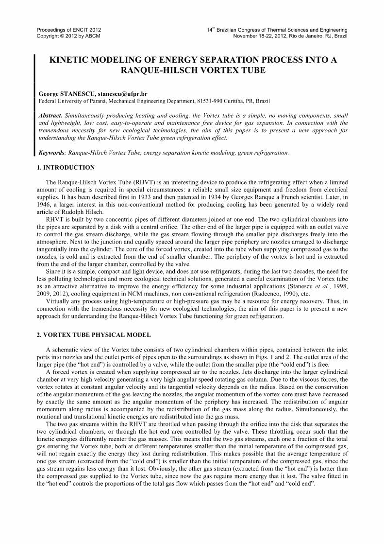
Figure 1a graphically presents the angular velocity variation along the radial direction. Based on the calculated positive and negative values ofVθ , now we could explain qualitatively, without any other supplemental hypothesis on the conservation of the angular momentum and redistribution of rotational and translational kinetic energies into a rotating gas column, the flow reversal at the RHVT axis and the division of the compressed gas entering the RHVT into a cooled gas stream and a hot gas stream.
Immediately after the formation of the high angular speed rotating air column inside the larger cylindrical chamber, the variation of the air pressure along the Vortex Tube radial direction in Fig. 1b reveals that the kinetic thermodynamic model presented in this paper captures well the Ranque-Hilsch Vortex Tube functioning. It is worth noting in this figure that the rotating gas column pressure is never less than the ambient pressure 1P ≥ .
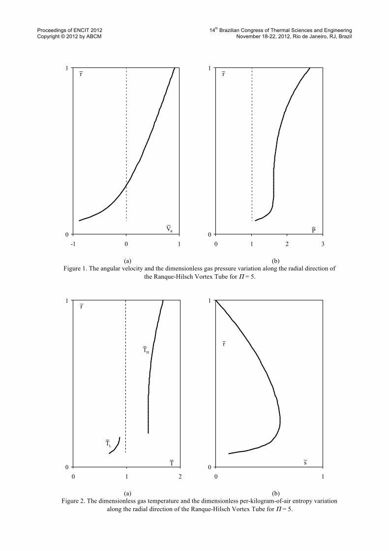
Figure 2a also reveals another interesting aspect of the RHVT functioning. The high angular speed rotating air column formation inside the larger Vortex Tube cylindrical chamber occurs simultaneously to the gas internal energy redistribution. The air temperature variation along the radial direction in Fig. 1a reveals the air temperature increase in the periphery and the air temperature decrease in the core.
During the high angular speed rotating air column formation process, to test the consistency of the proposed thermodynamic approach, we checked the dimensionless per-kilogram-of-air entropy variation. Since we have assumed that all the processes inside the Vortex Tube occurred adiabatically, data presented in Fig. 2b have also been used in order to calibrate the model such that to guarantee 0s ≥ .
Numerical results of the second-step numerical algorithm shown in Fig. 3 qualitatively explain based on the averaged temperature of air leaving the Vortex tube at “cold end” and “hot end”, ,L avT and ,H avT , the energy distribution between the cold and hot streams into the Vortex tube. The RHVT green refrigeration potential may be understood now based on the temperature difference between the ambient temperature and the cooled air leaving the device. 5. CONCLUSIONS
In connection with the tremendous necessity for new ecological technologies, the aim of this paper is to present a new approach of the Ranque-Hilsch Vortex Tube functioning.
The internal swirling flow is modeled by a set of ordinary differential equations that are integrated along the radial direction. The temperature variation along the radial direction is understood as a result of distribution of the kinetic energy through the swirling flow, i.e., temperature increase in the periphery and decrease in the core. The theoretical estimation of the flow reversal at the Vortex tube axis agrees well with the internal swirling flow results of Armfield and Fletcher (1991).
Focusing on a two-step kinetic mechanism of energy distribution inside the Vortex tube, this study assumes firstly that the air flow leaving the nozzles instantaneously evolves to a very high angular speed rotating air column.
Then, during the second step, the central rotating air column of diameter d separates by itself into the smaller pipe by flowing through the orifice into the disk separating the two cylindrical chambers. Simultaneously, the remaining annular rotating column at the periphery leaves the Vortex tube flowing through the control valve at the larger pipe outlet.
The mathematical problem consists of computing the velocity, temperature and air pressure distribution throughout the rotating air column and to calculate the average temperatures of the air extracted from the two Vortex tube exits. Consistency is numerically checked by monitoring the dimensionless per-kilogram-of-air entropy variation.
Proceedings of ENCIT 2012 14th Brazilian Congress of Thermal Sciences and Engineering Copyright © 2012 by ABCM November 18-22, 2012, Rio de Janeiro, RJ, Brazil
0
1
-1 0 1
0
1
0 1 2 3
(a) (b)
Figure 1. The angular velocity and the dimensionless gas pressure variation along the radial direction of the Ranque-Hilsch Vortex Tube for Π = 5.
0
1
0 1 2
0
1
0 1
(a) (b)
Figure 2. The dimensionless gas temperature and the dimensionless per-kilogram-of-air entropy variation along the radial direction of the Ranque-Hilsch Vortex Tube for Π = 5.
Vθ
r r
r
r
P
s T
HT
LT

Proceedings of ENCIT 2012 14th Brazilian Congress of Thermal Sciences and Engineering Copyright © 2012 by ABCM November 18-22, 2012, Rio de Janeiro, RJ, Brazil
0
1
0 1 2
Figure 3. Numerical results of the second-step numerical algorithm for Π = 5.
The thermodynamic model presented in this paper captures well two important issues related to the Ranque-Hilsch
Vortex Tube functioning. Pressure of the high angular speed rotating air column inside the larger RHVT cylindrical chamber is never less than the ambient pressure and the gas column formation process occurs simultaneously to the gas internal energy redistribution. Air temperature variation along the radial direction revealed the air temperature increase in the periphery and the air temperature decrease in the Ranque-Hilsch Vortex Tube core.
Study and optimization of the Ranque-Hilsch Vortex Tube design and functioning proved to be for many scientists and scholars a very challenging task. Future developments will be focused on improving the theoretical model and on optimizing the design of the RHVT green applications. 6. ACKNOWLEDGEMENTS
The author gratefully acknowledges the financial support of CNPq (Conselho Nacional de Desenvolvimento Científico e Tecnológico, Edital Universal 2009, Processo 480165/2009-2). 7. REFERENCES Armfield, S. W. & Fletcher, C. A. J., Int. J. Numer. Methods Fluids, vol. 6, pp. 541-556, 1986. Hilsch, R.,“Die Expansion von Gasen in zentrifugalfeld als Kälteprocess”. Zeitschrift für Naturforschung, Bd. 1, S. 208,
January 1946. Moran, J. M. & Shapiro, H. N., Fundamentals of Engineering Thermodynamics, John Wiley & Sons, Inc., 2000. Petrescu, S., Zaiser, J. & Petrescu, V., Lectures on New Sources of Energy, Vol. 1, Bucknell University, Lewisburg,
PA, USA, 1995. R433 Vortex Tube Refrigerator Technical Specification, P. A. Hilton Ltd., England, 1996. Radcenco, V., Vortex tubes for producing cooling and heating effects, Technical Publishing House, Bucharest,
Romania, 1990. Ranque, G. J., “Experiences sur la detente giratoire avec production simultanees d’un echappment d’air chaud et d’air
froid”, Journal Physique et le Radium, vol. 7, no 4, pp. 112, 1933. Ranque, G. J., “Method and apparatus for obtaining from fluid under pressure two currents of fluids at different
temperatures”, Patent USA No. 1,952,281/March 1934. Rocha, L. A. O., Stanescu, G., Vargas, J. V. C., 1997, “A theoretical and experimental study of the Vortex Tube”,
Proceedings of the 14th Brazilian Congress of Mechanical Engineering, 1997, Bauru, SP, Brazil, Vol. 1.
H,avT L,avT
HT
LT
r
T

Proceedings of ENCIT 2012 14th Brazilian Congress of Thermal Sciences and Engineering Copyright © 2012 by ABCM November 18-22, 2012, Rio de Janeiro, RJ, Brazil Stanescu, G., Rocha, L. A. O., Costa, J. A. V., Vargas, J. V. C., 1998, “Study of a Vortex-Tube equipped column
reactor for solid state fermentation”, Proceedings of the 7th Brazilian Congress of Engineering and Thermal Sciences, 1998, Rio de Janeiro, RJ, Brazil, Vol. 1. p.478 – 483.
Stanescu, G., Errera, M. R., Rocha, L. A. O., 2009, “Energy recovering during gas pressure letdown process in natural gas pipelines transmission”, Proceedings of the 20th International Congress of Mechanical Engineering, 2009, Gramado, RS.
Stanescu, G., 2012, “Ranque-Hilsch Vortex Tube Potential for Water Desalination", Proceedings of the 8th International Conference on Diffusion in Solids and Liquids, June 25-29, 2012, Istanbul, Turkey.
Stanescu, G., Cabral C. A. O., Carnio, M. S., 2012, “Experimental study on the Vortex Tube potential to increase the air moisture removal and carrying capability", Proceedings of the 15th International Conference on Experimental Mechanics, July 22-27, 2012, Porto, Portugal.
8. RESPONSIBILITY NOTICE
The author is the only responsible for the printed material included in this paper.