keyless connections etp® posi-lok® connections. keyless connections are ideal for positioning and...
TRANSCRIPT

Keyless ConnectionsETP®
Posi-Lok®
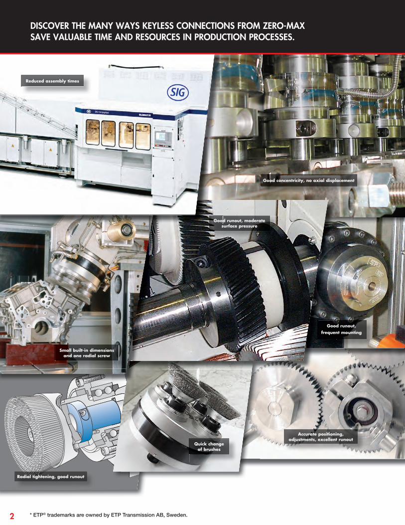
Small built-in dimensions and one radial screw
Quick change of brushes
Good runout, frequent mounting
Good runout, moderate surface pressure
Accurate positioning, adjustments, excellent runout
Radial tightening, good runout
Reduced assembly times
Good concentricity, no axial displacement
DISCOVER THE MANY WAYS KEYLESS CONNECTIONS FROM ZERO-MAX SAVE VALUABLE TIME AND RESOURCES IN PRODUCTION PROCESSES.
* ETP® trademarks are owned by ETP Transmission AB, Sweden.2

• Mounting or dismantling in less than 10 seconds• Shorten downtime for fi eld servicing• Fewer screws than alternative products
Zero-Max’s Posi-Lok and ETP* keyless connections are the perfect locking devices for shaft-to-hub connections. Keyless connections are ideal for positioning and locking shaft components in a system, and provide the best solution where keyways and tapers can weaken or cause excess wear to the shaft.
Our keyless connections also address applications for synchronizing moving parts. They enable precise mounting of shaft components where frequent readjustments are required, in systems where balance and runout are inherent problems, and where common fastening, adjusting, and holding of shaft components are required.
We offer keyless locking devices that are designed to solve specifi c application requirements, such as high transmittable torque. Our ETP-CLASSIC and ETP-EXPRESS keyless connections are available in stainless steel for corrosion protection and to handle frequent washdowns. The Posi-Lok model meets critical design requirements while being a competitive cost alternative.
REASONS TO USE KEYLESS CONNECTIONS
• Fast changeovers• Zero backlash and superior concentricity• Good corrosion resistance
See more keyless connection examples at www.zero-max.com
Zero backlash
Excellent runout, very low TIR
Precise and accurate positioning, adjustment
Easy to position and adjust with
one screw
Quick changes
Transmits high axial
forces, simple adjustment
Good runout, radial accessibility
3

zero-max.com
Transmittable Polar moment of inertia
WeightHub Bore Tolerance Shaft Tolerance
T FA Shaft side Hub side Upper Limit Lower Limit Grade Upper Limit Lower Limit Grade
Model lb ft lbf Force PSI Force PSI lb ft2 x10-6 lb mm mm mm mm
PSL-K-6-C 4 438 23,205 11,602 59 0.08 12.018 - 12.000 H7 6.000 - 5.982 h8
PSL-K-1/4-C 5 438 21,755 11,602 59 0.08 12.018 - 12.000 H7 6.350 - 6.328 h8
PSL-K-7-C 5 438 18,854 11,602 59 0.08 12.018 - 12.000 H7 7.000 - 6.978 h8
PSL-K-8-C 17 1,326 42,059 23,205 119 0.12 15.018 - 15.000 H7 8.000 - 7.978 h8
PSL-K-9-C 19 1,326 37,708 23,205 119 0.12 15.018 - 15.000 H7 9.000 - 8.978 h8
PSL-K-3/8-C 21 1,326 36,258 18,854 185 0.15 18.018 - 18.000 H7 9.525 - 9.503 h8
PSL-K-10-C 21 1,326 33,357 18,854 183 0.15 18.018 - 18.000 H7 10.000 - 9.978 h8
PSL-K-11-C 24 1,326 30,456 18,854 180 0.14 18.018 - 18.000 H7 11.000 - 10.973 h8
PSL-K-12-C 35 1,753 37,708 23,205 237 0.17 20.021 - 20.000 H7 12.000 - 11.973 h8
PSL-K-1/2-C 37 1,753 36,258 20,304 237 0.16 20.021 - 20.000 H7 12.700 - 12.673 h8
PSL-K-14-C 41 1,753 31,907 20,304 308 0.18 22.021 - 22.000 H7 14.000 - 13.973 h8
PSL-K-15-C 70 2,855 42,059 27,556 570 0.28 23.021 - 23.000 H7 15.000 - 14.973 h8
PSL-K-5/8-C 70 2,855 39,158 26,105 641 0.29 24.021 - 24.000 H7 15.875 - 15.848 h8
PSL-K-16-C 74 2,855 39,158 26,105 641 0.29 24.021 - 24.000 H7 16.000 - 15.973 h8
PSL-K-17-C 81 2,855 37,708 24,655 783 0.32 26.021 - 26.000 H7 17.000 - 16.973 h8
PSL-K-18-C 81 2,855 34,807 24,655 759 0.31 26.021 - 26.000 H7 18.000 - 17.973 h8
PSL-K-19-C 89 2,855 33,357 23,205 949 0.34 28.021 - 28.000 H7 19.000 - 18.967 h8
PSL-K-3/4-C 91 2,855 33,357 23,205 949 0.34 28.021 - 28.000 H7 19.050 - 19.017 h8
PSL-K-20-C 96 2,855 31,907 23,205 925 0.33 28.021 - 28.000 H7 20.000 - 19.967 h8
PSL-K-22-C 155 4,271 36,258 24,655 1,542 0.46 32.025 - 32.000 H7 22.000 - 21.967 h8
PSL-K-7/8-C 155 4,271 36,258 24,655 1,542 0.46 34.025 - 34.000 H7 22.225 - 22.192 h8
PSL-K-24-C 170 4,271 33,357 23,205 1,804 0.48 34.025 - 34.000 H7 24.000 - 23.967 h8
PSL-K-25-C 177 4,271 31,907 23,205 1,780 0.46 34.025 - 34.000 H7 25.000 - 24.967 h8
PSL-K-1-C 177 4,271 31,907 23,205 1,780 0.46 34.025 - 34.000 H7 25.400 - 25.367 h8
PSL-K-28-C 280 6,070 31,907 23,205 4,817 0.86 39.025 - 39.000 H7 28.000 - 27.967 h8
PSL-K-30-C 295 6,070 30,456 21,755 5,458 0.88 41.025 - 41.000 H7 30.000 - 29.967 h8
PSL-K-32-C 317 6,070 27,556 20,304 6,170 0.94 43.025 - 43.000 H7 32.000 - 31.961 h8
PSL-K-38-C 465 8,093 30,456 21,755 8,685 1.16 47.025 - 47.000 H7 38.000 - 37.961 h8
PSL-K-40-C 531 8,093 23,205 17,404 12,126 1.32 53.030 - 53.000 H7 40.000 - 39.961 h8
Posi-Lok® Bushing Keyless Connections
T = Transmittable torque when axial force is 0. FA = Transmittable axial force when torque is 0. ISO286-2 System of Limits and Fits
Performance Information
FEATURES • Provides solid connection between the shaft and
mounted device. Simple, friction grip design does not require use of keyways.
• Nickel plated finish provides protection from incidental contact with salts, water, solvents and other corrosive substances.
• Socket-head cap screws tighten quickly and easily.• Excellent axial and radial runout.• Stainless steel construction available upon request.
4

Tt = Recommended tightening torque for actuation screw. * L1 and L2 are valid before mounting.
Dimensions Screws
d D D1 D2 P L L1* L2* L3 L4No.
Dim Tt
Model mm mm mm mm mm mm mm mm mm mm M1 M2 In lb
PSL-K-6-C 6 12 25 23 17 10 20 24 3.5 5 2 M4 x 8 2-M4 18
PSL-K-1/4-C 6.35 12 25 23 17 10 20 24 3.5 5 2 M4 x 8 2-M4 18
PSL-K-7-C 7 12 25 23 17 10 20 24 3.5 5 2 M4 x 8 2-M4 18
PSL-K-8-C 8 15 28 26 20 12 24 28 5.0 5 3 M4 x 10 3-M4 35
PSL-K-9-C 9 15 28 26 20 12 24 28 5.0 5 3 M4 x 10 3-M4 35
PSL-K-3/8-C 9.53 18 31 29 23 12 24 28 5.0 5 3 M4 x 10 3-M4 35
PSL-K-10-C 10 18 31 29 23 12 24 28 5.0 5 3 M4 x 10 3-M4 35
PSL-K-11-C 11 18 31 29 23 12 24 28 5.0 5 3 M4 x 10 3-M4 35
PSL-K-12-C 12 20 33 31 25 12 24 28 5.0 5 4 M4 x 10 2-M4 35
PSL-K-1/2-C 12.70 20 33 31 25 12 24 28 5.0 5 4 M4 x 10 2-M4 35
PSL-K-14-C 14 22 35 33 27 12 24 28 5.0 5 4 M4 x 10 2-M4 35
PSL-K-15-C 15 23 39 36 29 14 29 34 6.0 7 4 M5 x 12 2-M5 71
PSL-K-5/8-C 15.88 24 40 37 30 14 29 34 6.0 7 4 M5 x 12 2-M5 71
PSL-K-16-C 16 24 40 37 30 14 29 34 6.0 7 4 M5 x 12 2-M5 71
PSL-K-17-C 17 26 42 39 32 14 29 34 6.0 7 4 M5 x 12 2-M5 71
PSL-K-18-C 18 26 42 39 32 14 29 34 6.0 7 4 M5 x 12 2-M5 71
PSL-K-19-C 19 28 44 41 34 14 29 34 6.0 7 4 M5 x 12 2-M5 71
PSL-K-3/4-C 19.05 28 44 41 34 14 29 34 6.0 7 4 M5 x 12 2-M5 71
PSL-K-20-C 20 28 44 41 34 14 29 34 6.0 7 4 M5 x 12 2-M5 71
PSL-K-22-C 22 32 48 45 38 16 33 38 6.5 8 6 M5 x 14 2-M5 71
PSL-K-7/8-C 22.23 34 48 45 38 16 33 38 6.5 8 6 M5 x 14 2-M5 71
PSL-K-24-C 24 34 50 47 40 16 33 38 6.5 8 6 M5 x 14 2-M5 71
PSL-K-25-C 25 34 50 47 40 16 33 38 6.5 8 6 M5 x 14 2-M5 71
PSL-K-1-C 25.40 34 50 47 40 16 33 38 6.7 8 6 M5 x 14 2-M5 71
PSL-K-28-C 28 39 62 59 47 20 39 45 7.5 9 6 M6 x 16 2-M6 124
PSL-K-30-C 30 41 64 61 49 20 39 45 7.5 9 6 M6 x 16 2-M6 124
PSL-K-32-C 32 43 66 63 51 20 39 45 7.5 9 6 M6 x 16 2-M6 124
PSL-K-38-C 38 47 70 67 55 20 43 49 8.0 10 8 M6 x 18 2-M6 124
PSL-K-40-C 40 53 76 73 61 20 43 49 8.0 10 8 M6 x 18 2-M6 124
Posi-Lok® Bushing Keyless Connections
DESIGN Mechanical locking wedge achieves high transmission of torque. Posi-Lok bushing is designed to provide excellent axial and radial runout in a broad range of shaft mount applications.
OPERATION Tightening of actuation bolts draws two opposing conical tapers up against their mutual contact surfaces forcing the inner and outer wall to expand against the shaft and hub fastening components to the shaft.
Dimensional Information
D1 P
L2
M1
M2
L1
LL4
L3
d D D2D1 P
L2
M1
M2
L1
LL4
L3
d D D2
5
zero-max.com
Transmittable Polar moment of inertia
WeightHub Bore Tolerance Shaft Tolerance
T FA FR Upper Limit Lower Limit Grade Upper Limit Lower Limit Grade
Model lb ft lbf lbf lb ft2 x10-3 lb mm mm mm mm
ETP-15 41 1,641 562 0.45 0.22 23.018 – 23.000 H7 15.000 – 14.982 h7
ETP-19 74 2,383 1,304 1.07 0.37 28.021 – 28.000 H7 19.020 – 18.967 k6-h8*
ETP-3/4 65 2,091 1,304 1.07 0.37 28.021 – 28.000 H7 19.070 – 19.017 k6-h8*
ETP-20 92 2,810 1,484 1.02 0.35 28.021 – 28.000 H7 20.020 – 19.967 k6-h8*
ETP-22 100 2,765 1,843 1.50 0.44 32.025 – 32.000 H7 22.020 – 21.967 k6-h8*
ETP-7/8 100 2,720 1,843 1.26 0.44 32.025 – 32.000 H7 22.250 – 22.197 k6-h8*
ETP-15/16 129 3,305 2,203 1.57 0.44 34.025 – 34.000 H7 23.830 – 23.777 k6-h8*
ETP-24 148 3,754 2,203 1.57 0.44 34.025 – 34.000 H7 24.020 – 23.967 k6-h8*
ETP-25 184 4,496 2,383 1.59 0.44 34.025 – 34.000 H7 25.020 – 24.967 k6-h8*
ETP-1 144 3,642 2,473 1.59 0.48 35.025 – 35.000 H7 25.420 – 25.367 k6-h8*
ETP-28 221 4,811 2,945 2.66 0.60 39.025 – 39.000 H7 28.020 – 27.967 k6-h8*
ETP-1-1/8 207 4,384 2,945 2.66 0.57 39.025 – 39.000 H7 28.600 – 28.547 k6-h8*
ETP-30 310 6,294 3,305 3.16 0.66 41.025 – 41.000 H7 30.020 – 29.967 k6-h8*
ETP-1-3/16 251 5,058 3,305 3.16 0.64 41.025 – 41.000 H7 30.180 – 30.121 k6-h8*
ETP-1-1/4 302 5,867 3,664 4.27 0.79 43.025 – 43.000 H7 31.770 – 31.711 k6-h8*
ETP-32 310 5,912 3,664 4.27 0.77 43.025 – 43.000 H7 32.020 – 31.961 k6-h8*
ETP-1-3/8 398 6,991 4,046 5.46 0.90 47.025 – 47.000 H7 34.950 – 34.891 k6-h8*
ETP-35 479 8,340 4,226 5.46 0.90 47.025 – 47.000 H7 35.020 – 34.961 k6-h8*
ETP-1-7/16 428 7,149 4,496 6.57 0.99 50.025 – 50.000 H7 36.530 – 36.471 k6-h8*
ETP-38 553 8,880 4,766 6.57 0.97 50.025 – 50.000 H7 38.020 – 37.961 k6-h8*
ETP-1-1/2 516 8,250 4,833 9.68 1.15 52.030 – 52.000 H7 38.120 – 38.061 k6-h8*
ETP-40 693 10,566 5,125 9.68 1.26 53.030 – 53.000 H7 40.020 – 39.961 k6-h8*
ETP-1-5/8 627 9,262 5,283 9.82 1.28 55.030 – 55.000 H7 41.300 – 41.241 k6-h8*
ETP-42 693 10,071 5,485 9.82 1.23 55.030 – 55.000 H7 42.020 – 41.961 k6-h8*
ETP-1-3/4 870 11,914 5,845 15.09 1.65 59.030 – 59.000 H7 44.470 – 44.411 k6-h8*
ETP-45 951 12,881 6,047 15.09 1.68 59.030 – 59.000 H7 45.020 – 44.961 k6-h8*
ETP-48 1,158 14,702 6,587 18.06 1.76 62.030 – 62.000 H7 48.020 – 47.961 k6-h8*
ETP-1-15/16 1,069 13,241 6,744 22.38 2.09 65.030 – 65.000 H7 49.230 – 49.171 k6-h8*
ETP-50 1,401 17,085 6,946 22.38 2.01 65.030 – 65.000 H7 50.020 – 49.961 k6-h8*
ETP-2 1,195 14,455 7,081 30.87 2.38 68.030 – 68.000 H7 50.821 – 50.754 k6-h8*
ETP-55 1,844 20,434 7,868 30.87 2.40 71.030 – 71.000 H7 55.021 – 54.954 k6-h8*
ETP-60 2,508 25,402 8,790 46.49 3.09 77.030 – 77.000 H7 60.021 – 59.954 k6-h8*
ETP-2-1/2 2,286 21,940 9,329 65.97 3.99 84.035 – 84.000 H7 63.521 – 63.454 k6-h8*
ETP-65 2,581 24,278 9,689 65.97 3.79 84.035 – 84.000 H7 65.021 – 64.954 k6-h8*
ETP-70 3,835 33,495 10,611 95.75 4.61 90.035 – 90.000 H7 70.021 – 69.954 k6-h8*
ETP-2-15/16 3,909 34,394 11,352 130.52 5.69 95.035 – 95.000 H7 74.631 – 74.564 k6-h8*
ETP-75 4,646 37,766 11,532 130.52 5.53 95.035 – 95.000 H7 75.021 – 74.954 k6-h8*
ETP-3 3,909 31,270 11,802 225.44 5.73 98.035 – 98.000 H7 76.221 – 76.154 k6-h8*
ETP-80 6,490 49,456 12,364 192.22 5.91 100.035 – 100.000 H7 80.021 – 79.954 k6-h8*
ETP-85 6,490 46,534 13,038 225.44 6.81 106.035 – 106.000 H7 85.025 – 84.946 k6-h8*
ETP-90 8,113 54,851 13,488 289.51 7.76 112.035 – 112.000 H7 90.025 – 89.946 k6-h8*
ETP-95 9,440 60,471 13,825 405.79 9.83 120.035 – 120.000 H7 95.025 – 94.946 k6-h8*
ETP-100 11,431 69,688 13,938 473.42 10.73 125.040 – 125.000 H7 100.025 – 99.946 k6-h8*
ETP-4 9,219 59,347 13,938 473.42 11.55 130.040 – 130.000 H7 101.630 – 101.546 k6-h8*
T = Transmittable torque when axial force is 0. FA = Transmittable axial force when torque is 0. FR = Maximum radial force during continuous operation.Maximum allowed bending torque = 15% of transmittable torque T. * The tolerance grade k6-h8 is a range between the upper limit of the ISO grade k6 and the lower limit of the ISO grade h8. Note: if the shaft is machined to a strict k6 tolerance range the transmittable torque will increase by 20%.
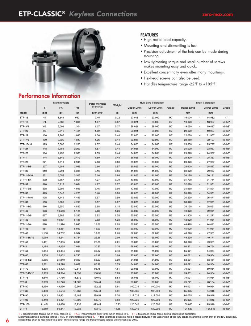
FEATURES • High radial load capacity.• Mounting and dismantling is fast.• Precision adjustment of the hub can be made during
mounting.• Low tightening torque and small number of screws
makes mounting easy and quick.• Excellent concentricity even after many mountings.• Hexhead screws can also be used.• Handles temperature range -22°F to +185°F.
ETP-CLASSIC® Keyless Connections
Performance Information
6
Dimensions Screws
d D D1 D2 L L1* L2*No. Dim
Tt
Model mm mm mm mm mm mm mm lb ft
ETP-15 15 23 38 28.5 17 30 35 3 M5 4.4
ETP-19 19 28 45 35.0 21 37 42 3 M5 5.9
ETP-3/4 19.05 28 45 35.0 21 35 40 3 M5 5.9
ETP-20 20 28 45 35.0 22 37 42 3 M5 5.9
ETP-22 22 32 49 40.0 22 37 42 4 M5 5.9
ETP-7/8 22.23 32 49 40.0 22 37 42 4 M5 5.9
ETP-15/16 23.81 34 49 40.0 25 39 44 4 M5 5.9
ETP-24 24 34 49 40.0 25 40 45 4 M5 5.9
ETP-25 25 34 49 40.0 27 43 48 4 M5 5.9
ETP-1 25.40 35 51 41.5 27 41 46 4 M5 5.9
ETP-28 28 39 55 46.0 29 45 50 4 M5 5.9
ETP-1-1/8 28.58 39 55 46.0 29 43 48 4 M5 5.9
ETP-30 30 41 57 47.5 32 47 52 4 M5 5.9
ETP-1-3/16 30.16 41 57 47.5 32 47 52 4 M5 5.9
ETP-1-1/4 31.75 43 60 50.5 34 50 55 4 M6 9.6
ETP-32 32 43 60 50.5 34 52 57 4 M5 5.9
ETP-1-3/8 34.93 47 63 53.5 37 53 58 6 M5 5.9
ETP-35 35 47 63 53.5 37 55 60 6 M5 5.9
ETP-1-7/16 36.51 50 65 56.0 37 54 59 6 M5 5.9
ETP-38 38 50 65 56.0 41 59 64 6 M5 5.9
ETP-1-1/2 38.10 52 68 59.0 41 57 62 6 M5 5.9
ETP-40 40 53 70 60.5 43 63 68 6 M5 5.9
ETP-1-5/8 41.28 55 70 61.0 44 63 68 6 M5 5.9
ETP-42 42 55 70 60.5 45 65 70 6 M5 5.9
ETP-1-3/4 44.45 59 77 66.5 49 67 73 6 M6 9.6
ETP-45 45 59 77 66.5 49 69 75 6 M6 9.6
ETP-48 48 62 80 69.5 52 73 79 6 M6 9.6
ETP-1-15/16 49.21 65 83 72.5 52 74 80 6 M6 9.6
ETP-50 50 65 83 72.5 53 76 82 6 M6 9.6
ETP-2 50.80 68 88 76.0 53 74 80 6 M6 9.6
ETP-55 55 71 88 78.0 58 82 88 8 M6 9.6
ETP-60 60 77 95 84.5 64 90 96 8 M6 9.6
ETP-2-1/2 63.50 84 107 93.0 62 86 94 6 M8 23.6
ETP-65 65 84 102 91.0 68 96 102 8 M6 9.6
ETP-70 70 90 113 99.0 72 99 107 6 M8 23.6
ETP-2-15/16 74.61 95 118 104 85 108 118 6 M8 23.6
ETP-75 75 95 118 104 85 114 122 6 M8 23.6
ETP-3 76.20 98 121 107 74 101 109 6 M8 23.6
ETP-80 80 100 123 109 90 120 128 6 M8 23.6
ETP-85 85 106 129 115 95 125 133 6 M8 23.6
ETP-90 90 112 135 121 100 133 141 8 M8 23.6
ETP-95 95 120 143 129 105 139 147 8 M8 23.6
ETP-100 100 125 148 134 110 145 153 8 M8 23.6
ETP-4 101.60 130 155 141 97 128 136 8 M8 23.6
Dimensional Information
Tt = Recommended tightening torque for actuation screw. * L1 and L2 are valid before mounting. Dimensions subject to alterations without notice
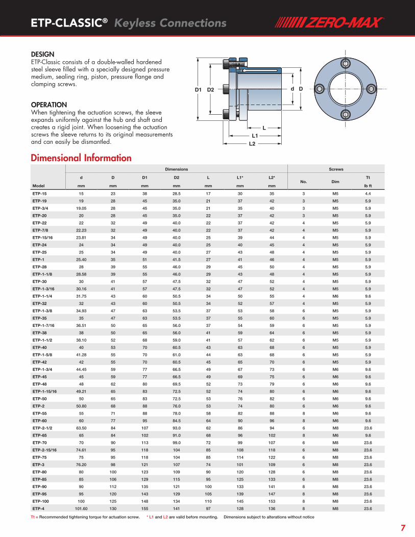
DESIGN ETP-Classic consists of a double-walled hardened steel sleeve filled with a specially designed pressure medium, sealing ring, piston, pressure flange and clamping screws.
OPERATION When tightening the actuation screws, the sleeve expands uniformly against the hub and shaft and creates a rigid joint. When loosening the actuation screws the sleeve returns to its original measurements and can easily be dismantled.
ETP-CLASSIC® Keyless Connections
D1 D2 Dd
L2L1
L
D1 D2 Dd
L2L1
L
7

zero-max.com
Transmittable Polar moment of inertia
WeightHub Bore Tolerance Shaft Tolerance
T FA FR Upper Limit Lower Limit Grade Upper Limit Lower Limit Grade
Model lb ft lbf lbf lb ft2 x10-3 lb mm mm mm mm
ETP-S19 39 1,124 1,304 1.07 0.33 28.021 – 28.000 H7 19.020 – 18.967 k6-h8*
ETP-S20 55 1,349 1,484 1.02 0.31 28.021 – 28.000 H7 20.000 – 19.948 h9
ETP-S25 89 2,248 2,383 1.59 0.37 34.025 – 34.000 H7 25.000 – 24.948 h9
ETP-S30 155 3,147 3,305 3.16 0.53 41.025 – 41.000 H7 30.000 – 29.948 h9
ETP-S35 243 4,271 4,226 5.46 0.71 47.025 – 47.000 H7 35.000 – 34.938 h9
ETP-S40 369 5,845 5,125 9.68 1.01 53.030 – 53.000 H7 40.000 – 39.938 h9
ETP-S45 516 6,969 6,047 15.09 1.26 59.030 – 59.000 H7 45.000 – 44.938 h9
ETP-S50 738 8,992 7,868 22.38 1.59 65.030 – 65.000 H7 50.000 – 49.938 h9
Dimensions Screws
d D D1 L L1* L2*No. Dim
Tt
Model mm mm mm mm mm mm lb ft
ETP-S19 19 28 45 13 26 31 3 M5 5.9
ETP-S20 20 28 45 15 28 33 3 M5 5.9
ETP-S25 25 34 49 15 29 34 4 M5 5.9
ETP-S30 30 41 57 20 34 39 4 M5 5.9
ETP-S35 35 47 63 22 38 43 6 M5 5.9
ETP-S40 40 53 70 25 42 47 6 M5 5.9
ETP-S45 45 59 77 28 45 51 6 M6 9.6
ETP-S50 50 65 83 26 45 51 6 M6 9.6
ETP-CLASSIC® S Keyless Connections
Dimensional Information
Performance Information
T = Transmittable torque when axial force is 0. FA = Transmittable axial force when torque is 0. FR = Maximum radial force during continuous operation.Maximum allowed bending torque = 15% of transmittable torque T. * The tolerance grade k6-h8 is a range between the upper limit of the ISO grade k6 and the lower limit of the ISO grade h8. Note: if the shaft is machined to a strict k6 tolerance range the transmittable torque will increase by 20%.
Tt = Recommended tightening torque for actuation screw. * L1 and L2 are valid before mounting. Dimensions subject to alterations without notice
FEATURES • Mounting and dismantling is fast.• Shortened ETP-CLASSIC for mounting shorter hub
components.• Precision adjustment of the hub can be made during
mounting.• Low tightening torque and small number of screws
makes mounting easy and quick.• Excellent concentricity even after many mountings.• Hexhead screws can also be used.• Handles temperature range -22°F to +185°F.
D1 D2 Dd
L2
L1
L
D1 D2 Dd
L2
L1
L
DESIGN ETP-CLASSIC S (short model) for applications requiring a smaller foot print. Same features as a standard ETP-CLASSIC. Consists of a double-walled hardened steel sleeve filled with a specially designed pressure medium, sealing ring, piston, pressure flange and clamping screws.
OPERATION When tightening the actuation screws, the sleeve expands uniformly against the hub and shaft and creates a rigid joint. When loosening the actuation screws the sleeve returns to its original measurements and can easily be dismantled.
8
D1 D2 Dd
L2
L1
L
D1 D2 Dd
L2
L1
L
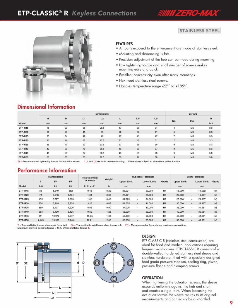
FEATURES • All parts exposed to the environment are made of stainless steel.• Mounting and dismantling is fast.• Precision adjustment of the hub can be made during mounting.• Low tightening torque and small number of screws makes
mounting easy and quick.• Excellent concentricity even after many mountings.• Hex head stainless steel screws.• Handles temperature range -22°F to +185°F.
Transmittable Polar moment of inertia
WeightHub Bore Tolerance Shaft Tolerance
T FA FR Upper Limit Lower Limit Grade Upper Limit Lower Limit Grade
Model lb ft lbf lbf lb ft2 x10-3 lb mm mm mm mm
ETP-R15 33 1,349 562 0.45 0.22 23.021 – 23.000 H7 15.000 – 14.982 h7
ETP-R20 74 2,248 1,484 1.04 0.35 28.021 – 28.000 H7 20.000 – 19.967 h8
ETP-R25 155 3,777 2,383 1.66 0.46 34.025 – 34.000 H7 25.000 – 24.967 h8
ETP-R30 258 5,215 3,305 3.25 0.66 41.025 – 41.000 H7 30.000 – 29.967 h8
ETP-R35 369 6,407 4,226 5.55 0.90 47.025 – 47.000 H7 35.000 – 34.961 h8
ETP-R40 553 8,430 5,125 9.82 1.28 53.030 – 53.000 H7 40.000 – 39.961 h8
ETP-R45 811 10,970 6,047 15.35 1.63 59.030 – 59.000 H7 45.000 – 44.961 h8
ETP-R50 1,143 13,938 6,946 22.71 2.03 65.030 – 65.000 H7 50.000 – 49.961 h8
Dimensions Screws
d D D1 D2 L L1* L2*No. Dim
Tt
Model mm mm mm mm mm mm mm lb ft
ETP-R15 15 23 38 28.5 17 30 34 4 M5 3.3
ETP-R20 20 28 45 35 22 37 41 5 M5 3.3
ETP-R25 25 34 49 40 27 43 47 7 M5 3.3
ETP-R30 30 41 57 47.5 32 47 51 7 M5 3.3
ETP-R35 35 47 63 53.5 37 55 59 9 M5 3.3
ETP-R40 40 53 70 60.5 43 63 67 9 M5 3.3
ETP-R45 45 59 77 66.5 49 69 73 9 M6 5.8
ETP-R50 50 65 83 72.5 53 76 80 9 M6 5.8
ETP-CLASSIC® R Keyless Connections
Dimensional Information
Performance Information
T = Transmittable torque when axial force is 0. FA = Transmittable axial force when torque is 0. FR = Maximum radial force during continuous operation.Maximum allowed bending torque = 15% of transmittable torque T.
Tt = Recommended tightening torque for actuation screw. * L1 and L2 are valid before mounting. Dimensions subject to alterations without notice
DESIGN ETP-CLASSIC R (stainless steel construction) are ideal for food and medical applications requiring frequent wash-downs. ETP-CLASSIC R consists of a double-walled hardened stainless steel sleeve and stainless hardware, filled with a specially designed food-grade pressure medium, sealing ring, piston, pressure flange and clamping screws.
OPERATION When tightening the actuation screws, the sleeve expands uniformly against the hub and shaft and creates a rigid joint. When loosening the actuation screws the sleeve returns to its original measurements and can easily be dismantled.
STAINLESS STEEL
9

zero-max.com
Transmittable Polar moment of inertia
WeightBore Tolerance Shaft Tolerance
T FA FR Upper Limit Lower Limit Grade Upper Limit Lower Limit Grade
Model lb ft lbf lbf lb ft2 x10-3 lb mm mm mm mm
ETP-E15 34 1,146 112 0.95 0.35 18.018 – 18.000 H7 15.000 – 14.982 h7
ETP-E5/8 39 1,236 112 1.19 0.37 19.000 – 19.018 H7 15.875 – 15.848 h8
ETP-E19 63 1,641 225 1.42 0.44 23.021 – 23.000 H7 19.020 – 18.979 k6-h7*
ETP-E3/4 63 1,641 225 1.42 0.44 23.000 – 23.021 H7 19.050 – 19.017 h8
ETP-E20 81 2,046 225 1.66 0.46 24.021 – 24.000 H7 20.000 – 19.967 h8
ETP-E22 96 2,158 270 2.37 0.55 27.021 – 27.000 H7 22.020 – 21.979 k6-h7*
ETP-E7/8 96 2,158 270 2.37 0.55 27.000 – 27.021 H7 22.225 – 22.192 h8
ETP-E24 140 2,922 315 2.61 0.60 29.021 – 29.000 H7 24.020 – 23.979 k6-h7*
ETP-E25 170 3,372 337 2.85 0.60 30.021 – 30.000 H7 25.000 – 24.967 h8
ETP-E1 140 2,698 337 3.08 0.64 31.000 – 31.025 H7 25.400 – 25.367 h8
ETP-E28 207 3,597 405 4.03 0.75 34.025 – 34.000 H7 28.020 – 27.979 k6-h7*
ETP-E1-1/8 214 3,597 405 4.27 0.77 35.000 – 35.025 H7 28.575 – 28.542 h8
ETP-E30 280 4,721 450 4.51 0.77 36.025 – 36.000 H7 30.000 – 29.967 h8
ETP-E1-1/4 317 4,946 495 5.93 0.93 39.000 – 39.025 H7 31.750 – 31.711 h8
ETP-E32 325 4,946 495 5.93 0.93 39.025 – 39.000 H7 32.020 – 31.975 k6-h7*
ETP-E1-3/8 472 6,744 562 7.59 1.06 42.000 – 42.025 H7 34.925 – 34.886 h8
ETP-E35 472 6,744 562 7.59 1.06 42.025 – 42.000 H7 35.000 – 34.961 h8
ETP-E1-7/16 546 7,418 584 8.54 1.15 44.000 – 44.025 H7 36.513 – 36.474 h8
ETP-E38 656 8,542 629 18.04 1.85 46.025 – 46.000 H7 38.020 – 37.975 k6-h7*
ETP-E1-1/2 656 8,542 629 18.04 1.85 46.000 – 46.025 H7 38.100 – 38.061 h8
ETP-E40 811 10,116 674 19.93 1.94 48.025 – 48.000 H7 40.000 – 39.961 h8
ETP-E42 811 9,666 719 23.02 2.12 51.030 – 51.000 H7 42.020 – 41.975 k6-h7*
ETP-E1-3/4 1,033 11,465 787 28.48 2.42 54.000 – 54.030 H7 44.450 – 44.411 h8
ETP-E45 1,033 11,465 787 27.76 2.31 54.030 – 54.000 H7 45.000 – 44.961 h8
ETP-E48 1,254 12,814 899 34.65 2.67 59.030 – 59.000 H7 48.020 – 47.975 k6-h7*
ETP-E1-15/16 1,401 14,162 967 37.26 2.80 60.000 – 60.030 H7 49.213 – 49.174 h8
ETP-E50 1,401 14,162 1,012 36.07 2.64 60.030 – 60.000 H7 50.000 – 49.961 h8
ETP-E2 1,401 13,938 1,012 40.82 2.82 61.000 – 61.030 H7 50.800 – 50.754 h8
ETP-E55 1,770 15,961 1,124 51.73 3.31 67.030 – 67.000 H7 55.021 – 54.970 k6-h7*
ETP-E60 2,434 20,232 1,191 75.23 4.08 73.030 – 73.000 H7 60.000 – 59.954 h8
ETP-E2-1/2 2,950 23,604 1,214 88.75 4.50 77.000 – 77.030 H7 63.500 – 63.454 h8
ETP-E65 3,245 25,178 1,258 97.30 4.69 85.035 – 85.000 H7 65.000 – 64.954 h8
ETP-E70 4,130 29,224 1,439 168.96 6.70 85.035 – 85.000 H7 70.000 – 69.954 h8
ETP-E3 5,531 35,968 1,574 213.81 7.67 91.000 – 91.035 H7 76.200 – 76.154 h8
ETP-E80 6,416 40,464 1,686 245.61 8.27 97.035 – 97.000 H7 80.000 – 79.954 h8
ETP-E90 8,850 49,456 1,933 360.70 10.58 109.035 – 109.000 H7 90.000 – 89.946 h8
ETP-E100 12,538 62,944 2,181 519.69 13.00 121.040 – 121.000 H7 100.000 – 99.946 h8
FEATURES • Fast and frequent mounting/dismantling with a
single actuation screw.• Radial screw positioning saves space along the
shaft.• Accurate positioning. No axial movement when
mounting.• Uniform surface pressure against shaft and hub
prevents damage to surfaces and enables the use of small diameter hubs.
• Handles temperature range -22°F to 185°F.• Excellent runout, ≤0.02 mm, even after several
mountings.
ETP-EXPRESS® Keyless Connections
Performance Information
T = Transmittable torque when axial force is 0. FA = Transmittable axial force when torque is 0. FR = Maximum radial force during continuous operation.Maximum allowed bending torque = 5% of transmittable torque T. * The tolerance grade k6-h7 is a range between the upper limit of the ISO grade k6 and the lower limit of the ISO grade h7.
10

ETP-EXPRESS® Keyless Connections
Dimensional Information
Tt = Recommended tightening torque for actuation screw. Further tightening does not increase the pressure in the connection. * D2 is valid before mounting ** Pressure screws positioned in the same direction. Dimensions subject to alterations without notice
DESIGN ETP-EXPRESS consists of a double-walled hardened steel sleeve and flange filled with a pressure medium. Located in the flange are one or two actuation screws and piston with seal, used to pressurize and maintain pressure in the connection.
OPERATION When the actuation screw is tightened, the double-walled sleeve expands uniformly against the shaft and hub and creates a rigid friction joint. Dismantling is done by loosening the screw which returns the ETP-Express to its original dimensions. It can then easily be dismantled.
R
D2
D1L1L
N
d D
R
D2
D1L1L
N
d D
Dimensions Screws
d D D1 D2* L L1Dim.
R N Tt
Model mm mm mm mm mm mm mm mm lb ft
ETP-E15 15 18 46.0 48.9 25 39 M10 15.1 5 3.69
ETP-E5/8 15.88 19 47.0 49.8 26 40 M10 15.6 5 3.69
ETP-E19 19 23 50.5 53.0 28 42 M10 17.4 5 3.69
ETP-E3/4 19.05 23 50.5 53.0 28 42 M10 17.4 5 3.69
ETP-E20 20 24 51.5 54.1 30 44 M10 18 5 3.69
ETP-E22 22 27 55.5 60.5 32 46 M10 19.3 5 3.69
ETP-E7/8 22.23 27 55.5 60.5 32 46 M10 19.3 5 3.69
ETP-E24 24 29 57.5 62.3 33 47 M10 20.3 5 3.69
ETP-E25 25 30 58.0 62.9 35 49 M10 20.8 5 3.69
ETP-E1 25.40 31 59.0 63.8 35 49 M10 21.2 5 3.69
ETP-E28 28 34 63.0 69.6 38 52 M10 22.6 5 3.69
ETP-E1-1/8 28.58 35 63.5 70.1 39 53 M10 23.0 5 3.69
ETP-E30 30 36 64.5 71.0 40 54 M10 23.6 5 3.69
ETP-E1-1/4 31.75 39 68.5 77.7 42 56 M10 24.8 5 3.69
ETP-E32 32 39 68.5 77.7 42 56 M10 24.8 5 3.69
ETP-E1-3/8 34.93 42 73.0 85.1 45 59 M10 26.4 5 3.69
ETP-E35 35 42 73.0 85.1 45 59 M10 26.4 5 3.69
ETP-E1-7/16 36.52 44 74.5 86.6 48 62 M10 27.3 5 3.69
ETP-E38 38 46 84.5 89.5 52 72 M16 31.0 8 15.49
ETP-E1-1/2 38.10 46 84.5 89.5 52 72 M16 31.0 8 15.49
ETP-E40 40 48 86.5 91.2 55 75 M16 32.0 8 15.49
ETP-E42 42 51 89.0 93.5 56 76 M16 33.2 8 15.49
ETP-E1-3/4 44.45 54 93.0 100.3 58 78 M16 34.8 8 15.49
ETP-E45 45 54 93.0 100.3 58 78 M16 34.8 8 15.49
ETP-E48 48 59 97.0 103.8 59 79 M16 36.8 8 15.49
ETP-E1-15/16 49.22 60 98.5 105.1 60 80 M16 37.5 8 15.49
ETP-E50 50 60 98.5 105.1 60 80 M16 37.5 8 15.49
ETP-E2 50.8 61 101.5 111.8 60 80 M16 38.0 8 15.49
ETP-E55 55 67 106.0 115.9 65 85 M16 40.5 8 15.49
ETP-E60 60 73 115.5 132.7 70 90 M16 43.3 8 15.49
ETP-E2-1/2 63.50 77 119.0 134.6 73 93 M16 45.1 8 15.49
ETP-E65 65 79 120.5 137.0 75 95 M16 46.1 8 21.00
ETP-E70 70 85 135.5 153.9 85 109 M20 50.5 10 28.76
ETP-E3 76.20 92 141.5 157.8 91 115 M20 54.1 10 28.76
ETP-E80 80 97 145.5 162.6 95 119 M20 56.3 10 28.76
ETP-E90 90 109 155.5 171.7 105 129 2 x M20** 61.8 10 28.76
ETP-E100 100 121 166.0 181.0 115 139 2 x M20** 67.3 10 28.76
11
zero-max.com
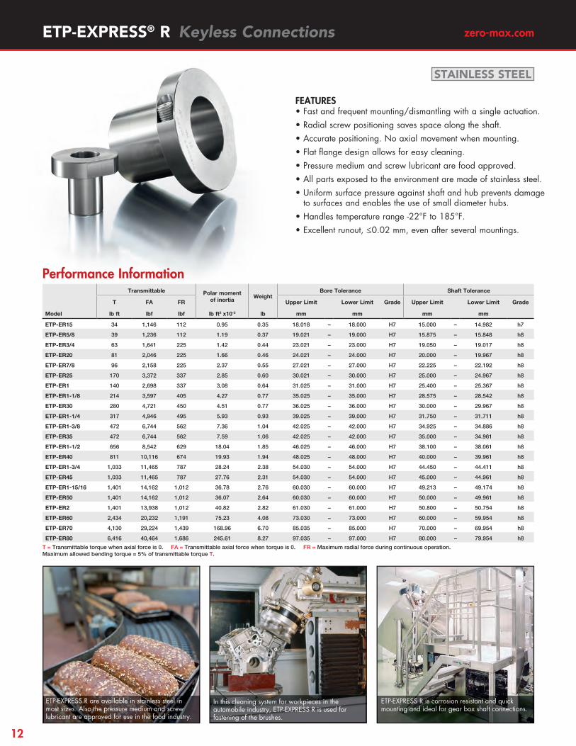
FEATURES• Fast and frequent mounting/dismantling with a single actuation.• Radial screw positioning saves space along the shaft.• Accurate positioning. No axial movement when mounting.• Flat fl ange design allows for easy cleaning.• Pressure medium and screw lubricant are food approved.• All parts exposed to the environment are made of stainless steel.• Uniform surface pressure against shaft and hub prevents damage
to surfaces and enables the use of small diameter hubs.• Handles temperature range -22°F to 185°F.• Excellent runout, ≤0.02 mm, even after several mountings.
Transmittable Polar moment of inertia
WeightBore Tolerance Shaft Tolerance
T FA FR Upper Limit Lower Limit Grade Upper Limit Lower Limit Grade
Model lb ft lbf lbf lb ft2 x10-3 lb mm mm mm mm
ETP-ER15 34 1,146 112 0.95 0.35 18.018 – 18.000 H7 15.000 – 14.982 h7
ETP-ER5/8 39 1,236 112 1.19 0.37 19.021 – 19.000 H7 15.875 – 15.848 h8
ETP-ER3/4 63 1,641 225 1.42 0.44 23.021 – 23.000 H7 19.050 – 19.017 h8
ETP-ER20 81 2,046 225 1.66 0.46 24.021 – 24.000 H7 20.000 – 19.967 h8
ETP-ER7/8 96 2,158 225 2.37 0.55 27.021 – 27.000 H7 22.225 – 22.192 h8
ETP-ER25 170 3,372 337 2.85 0.60 30.021 – 30.000 H7 25.000 – 24.967 h8
ETP-ER1 140 2,698 337 3.08 0.64 31.025 – 31.000 H7 25.400 – 25.367 h8
ETP-ER1-1/8 214 3,597 405 4.27 0.77 35.025 – 35.000 H7 28.575 – 28.542 h8
ETP-ER30 280 4,721 450 4.51 0.77 36.025 – 36.000 H7 30.000 – 29.967 h8
ETP-ER1-1/4 317 4,946 495 5.93 0.93 39.025 – 39.000 H7 31.750 – 31.711 h8
ETP-ER1-3/8 472 6,744 562 7.36 1.04 42.025 – 42.000 H7 34.925 – 34.886 h8
ETP-ER35 472 6,744 562 7.59 1.06 42.025 – 42.000 H7 35.000 – 34.961 h8
ETP-ER1-1/2 656 8,542 629 18.04 1.85 46.025 – 46.000 H7 38.100 – 38.061 h8
ETP-ER40 811 10,116 674 19.93 1.94 48.025 – 48.000 H7 40.000 – 39.961 h8
ETP-ER1-3/4 1,033 11,465 787 28.24 2.38 54.030 – 54.000 H7 44.450 – 44.411 h8
ETP-ER45 1,033 11,465 787 27.76 2.31 54.030 – 54.000 H7 45.000 – 44.961 h8
ETP-ER1-15/16 1,401 14,162 1,012 36.78 2.76 60.030 – 60.000 H7 49.213 – 49.174 h8
ETP-ER50 1,401 14,162 1,012 36.07 2.64 60.030 – 60.000 H7 50.000 – 49.961 h8
ETP-ER2 1,401 13,938 1,012 40.82 2.82 61.030 – 61.000 H7 50.800 – 50.754 h8
ETP-ER60 2,434 20,232 1,191 75.23 4.08 73.030 – 73.000 H7 60.000 – 59.954 h8
ETP-ER70 4,130 29,224 1,439 168.96 6.70 85.035 – 85.000 H7 70.000 – 69.954 h8
ETP-ER80 6,416 40,464 1,686 245.61 8.27 97.035 – 97.000 H7 80.000 – 79.954 h8
ETP-EXPRESS® R Keyless Connections
Performance Information
T = Transmittable torque when axial force is 0. FA = Transmittable axial force when torque is 0. FR = Maximum radial force during continuous operation.Maximum allowed bending torque = 5% of transmittable torque T.
ETP-EXPRESS R are available in stainless steel in most sizes. Also the pressure medium and screw lubricant are approved for use in the food industry.
In this cleaning system for workpieces in the automobile industry, ETP-EXPRESS R is used for fastening of the brushes.
ETP-EXPRESS R is corrosion resistant and quick mounting and ideal for gear box shaft connections.
STAINLESS STEEL
12

R N
d D
L
L1D1
r
V°
R N
d D
L
L1D1
r
V°
ETP-EXPRESS® R Keyless Connections
Dimensional Information
Tt = Recommended tightening torque for actuation screw. Further tightening does not increase the pressure in the connection. * D2 is valid before mounting Dimensions subject to alterations without notice
ETP-EXPRESS R is used to make sure that the piston is locked in an exact position vertically.
ETP-EXPRESS R is used for adjustment and locking of the lower shaft to which the parts are fixed.
Easy adjustment of chains, relative to each other, and location of the sprockets, with ETP-EXPRESS R.
ETP-EXPRESS R connects gearbox drives in a mixer for quick mounting in food industry.
DESIGNETP-EXPRESS R (stainless steel construction) consists of a double-walled hardened stainless steel sleeve and fl ange fi lled with a food-grade pressure medium. Located in the fl ange is a single actuation screw piston with seal, used to pressurize and maintain pressure in the connection.
OPERATIONWhen the actuation screw is tightened, the double-walled sleeve expands uniformly against shaft and hub and creates a rigid friction joint. Dismantling is done by loosening the screw which returns the ETP-EXPRESS R to its original dimensions. It can then easily be dismantled.
STAINLESS STEEL
Dimensions Screws
d D D1 D2* L L1 r V°Dim.
R N Tt
Model mm mm mm mm mm mm mm degrees mm mm lb ft
ETP-ER15 15 18 46.0 48.9 25 39 19.9 53 M10 15.1 5 3.69
ETP-ER5/8 15.88 19 47.0 49.8 26 40 20.3 54 M10 15.6 5 3.69
ETP-ER3/4 19.05 23 50.5 53 28 42 21.9 55 M10 17.4 5 3.69
ETP-ER20 20 24 51.5 54.1 30 44 22.6 56 M10 18.0 5 3.69
ETP-ER7/8 22.23 27 55.5 60.5 32 46 24.4 57 M10 19.3 5 3.69
ETP-ER25 25 30 58.0 62.9 35 49 26.1 58 M10 20.8 5 3.69
ETP-ER1 25.4 31 59.0 63.8 35 49 25.8 58 M10 21.2 5 3.69
ETP-ER1-1/8 28.58 35 63.5 70.1 39 53 28.5 59 M10 23.0 5 3.69
ETP-ER30 30 36 64.5 71 40 54 29.1 59 M10 23.6 5 3.69
ETP-ER1-1/4 31.75 39 68.5 77.7 42 56 31.1 58 M10 24.8 5 3.69
ETP-ER1-3/8 34.93 42 73.0 85.1 45 59 31.9 60.5 M10 26.4 5 3.69
ETP-ER35 35 42 73.0 85.1 45 59 33.7 58 M10 26.4 5 3.69
ETP-ER1-1/2 38 46 84.5 89.5 52 72 36.6 58 M16 31.0 8 15.49
ETP-ER40 40 48 86.5 91.2 55 75 37.7 59 M16 32.0 8 15.49
ETP-ER1-3/4 44.45 54 93.0 100.3 58 78 41.1 59 M16 34.8 8 15.49
ETP-ER45 45 54 93.0 100.3 58 78 41.1 61 M16 34.8 8 15.49
ETP-ER1-15/16 49.22 60 98.5 105.1 60 80 43.7 60 M16 37.5 8 15.49
ETP-ER50 50 60 98.5 105.1 60 80 43.7 62 M16 37.5 8 15.49
ETP-ER2 50.80 61 101.5 111.8 60 80 45.2 60 M16 38.0 8 15.49
ETP-ER60 60 73 115.5 132.7 70 90 53.3 59 M16 43.3 8 15.49
ETP-ER70 70 85 135.5 153.9 85 109 62.0 59 M20 50.8 10 28.76
ETP-ER80 80 97 145.5 162.6 95 119 65.9 61 M20 56.3 10 28.76
13

zero-max.com
Transmittable Polar moment of inertia
WeightBore Tolerance Shaft Tolerance
T FA FR Upper Limit Lower Limit Grade Upper Limit Lower Limit Grade
Model lb ft lbf lbf lb ft2 x10-3 lb mm mm mm mm
ETP-T15 37 1,124 225 2.14 0.55 19.018 – 19.000 H7 15.000 – 14.973 h8
ETP-T20 107 2,698 450 3.56 0.71 25.021 – 25.000 H7 20.000 – 19.967 h8
ETP-T25 184 3,597 674 9.02 1.28 32.021 – 32.000 H7 25.000 – 24.961 h8
ETP-T1 184 3,597 674 9.02 1.28 32.021 – 32.000 H7 25.400 – 25.361 h8
ETP-T30 369 5,845 899 12.81 1.52 38.025 – 38.000 H7 30.000 – 29.961 h8
ETP-T1-1/4 376 5,620 899 15.19 1.72 41.025 – 41.000 H7 31.750 – 31.711 h8
ETP-T32 376 5,620 899 15.19 1.72 41.025 – 41.000 H7 32.000 – 31.961 h8
ETP-T35 546 7,643 1,124 17.80 1.85 44.025 – 44.000 H7 35.000 – 34.961 h8
ETP-T1-1/2 649 8,093 1,124 26.10 2.38 50.025 – 50.000 H7 38.100 – 38.061 h8
ETP-T40 885 10,566 1,349 30.85 2.60 52.025 – 52.000 H7 40.000 – 39.954 h8
ETP-T45 1,254 13,938 1,574 35.60 2.73 56.025 – 56.000 H7 45.000 – 44.954 h8
ETP-T50 1,659 15,961 2,023 54.58 3.62 65.025 – 65.000 H7 50.000 – 49.954 h8
ETP-T60 3,245 26,751 2,698 118.65 5.53 75.030 – 75.000 H7 60.000 – 59.954 h8
ETP-T70 5,163 35,518 2,922 211.20 8.05 90.030 – 90.000 H7 70.000 – 69.946 h8
ETP-T75 6,343 41,138 3,147 284.76 9.26 95.030 – 95.000 H7 75.000 – 74.946 h8
ETP-T80 8,039 49,006 3,372 355.96 10.69 100.030 – 100.000 H7 80.000 – 79.946 h8
ETP-T90 11,431 62,270 3,822 522.07 11.99 112.035 – 112.000 H7 90.000 – 89.946 h8
ETP-T100 15,488 75,308 4,271 783.10 13.62 125.035 – 125.000 H7 100.000 – 99.937 h8
ETP-T110 20,650 92,168 4,721 1,020.41 15.61 138.035 – 138.000 H7 110.000 – 109.937 h8
ETP-T120 21,388 88,346 5,170 1,281.44 21.96 150.035 – 150.000 H7 120.000 – 119.937 h8
ETP-T130 23,600 88,346 5,620 1,779.78 23.94 163.040 – 163.000 H7 130.000 – 129.937 h8
FEATURES• Extremely fast mounting/dismantling with only one or
two screws.
• Can be mounted/dismantled 1000´s of times.
• Extremely good concentricity, ≤0.006 mm, even after several mountings.
• Dual sealing system.
• Radial tightening of the screw saves space along the shaft.
• Small built-in dimensions.
• Accurate positioning, no axial movement when mounting.
• Handles temperature range -22°F to 230°F.
ETP-TECHNO® Keyless Connections
Performance Information
T = Transmittable torque when axial force is 0. FA = Transmittable axial force when torque is 0. FR = Maximum radial force during continuous operation.Maximum allowed bending torque = 10% of transmittable torque T.
ETP-TECHNO is especially designed for applications where fast frequent changes or adjustments, with high precision are needed.
In a test rig for vehicle gearboxes the output shaft is connected to a torque limiter with ETP-TECHNO to control the torque transmission.
A gear of a special soft fibre material is fastened with ETP-TECHNO in special design for operating this printing machine.
14
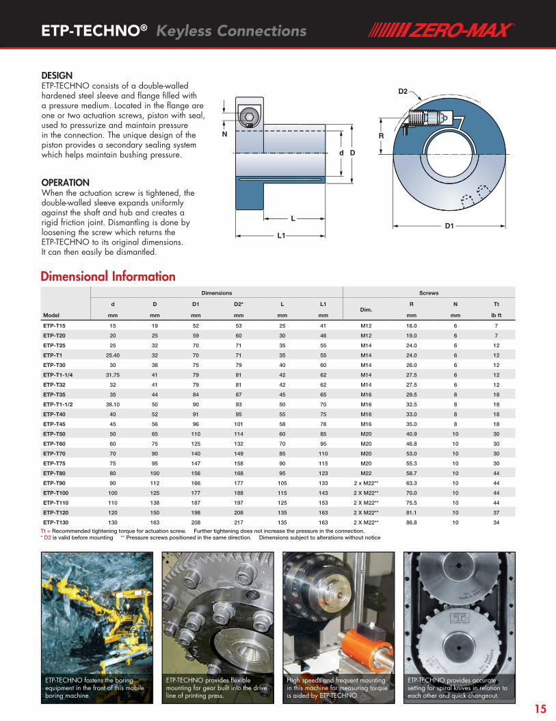
Dimensions Screws
d D D1 D2* L L1Dim.
R N Tt
Model mm mm mm mm mm mm mm mm lb ft
ETP-T15 15 19 52 53 25 41 M12 16.0 6 7
ETP-T20 20 25 59 60 30 46 M12 19.0 6 7
ETP-T25 25 32 70 71 35 55 M14 24.0 6 12
ETP-T1 25.40 32 70 71 35 55 M14 24.0 6 12
ETP-T30 30 38 75 79 40 60 M14 26.0 6 12
ETP-T1-1/4 31.75 41 79 81 42 62 M14 27.5 6 12
ETP-T32 32 41 79 81 42 62 M14 27.5 6 12
ETP-T35 35 44 84 87 45 65 M16 29.5 8 18
ETP-T1-1/2 38.10 50 90 93 50 70 M16 32.5 8 18
ETP-T40 40 52 91 95 55 75 M16 33.0 8 18
ETP-T45 45 56 96 101 58 78 M16 35.0 8 18
ETP-T50 50 65 110 114 60 85 M20 40.9 10 30
ETP-T60 60 75 125 132 70 95 M20 46.8 10 30
ETP-T70 70 90 140 149 85 110 M20 53.0 10 30
ETP-T75 75 95 147 158 90 115 M20 55.3 10 30
ETP-T80 80 100 156 168 95 123 M22 58.7 10 44
ETP-T90 90 112 166 177 105 133 2 x M22** 63.3 10 44
ETP-T100 100 125 177 188 115 143 2 X M22** 70.0 10 44
ETP-T110 110 138 187 197 125 153 2 X M22** 75.5 10 44
ETP-T120 120 150 198 208 135 163 2 X M22** 81.1 10 37
ETP-T130 130 163 208 217 135 163 2 X M22** 86.8 10 34
ETP-TECHNO® Keyless Connections
Dimensional Information
Tt = Recommended tightening torque for actuation screw. Further tightening does not increase the pressure in the connection. * D2 is valid before mounting ** Pressure screws positioned in the same direction. Dimensions subject to alterations without notice
ETP-TECHNO fastens the boring equipment in the front of this mobile boring machine.
ETP-TECHNO provides flexible mounting for gear built into the drive line of printing press.
High speeds and frequent mounting in this machine for measuring torque is aided by ETP-TECHNO.
ETP-TECHNO provides accurate setting for spiral knives in relation to each other and quick changeout.
D2
R
D1L1
L
d D
N
D2
R
D1L1
L
d D
N
DESIGNETP-TECHNO consists of a double-walled hardened steel sleeve and fl ange fi lled with a pressure medium. Located in the fl ange are one or two actuation screws, piston with seal, used to pressurize and maintain pressure in the connection. The unique design of the piston provides a secondary sealing system which helps maintain bushing pressure.
OPERATIONWhen the actuation screw is tightened, the double-walled sleeve expands uniformly against the shaft and hub and creates a rigid friction joint. Dismantling is done by loosening the screw which returns the ETP-TECHNO to its original dimensions. It can then easily be dismantled.
15

zero-max.com
Transmittable Polar moment of inertia
WeightBore Tolerance Shaft Tolerance
T FA FR Upper Limit Lower Limit Grade Upper Limit Lower Limit Grade
Model lb ft lbf lbf lb ft2 x10-3 lb mm mm mm mm
ETP-P15 44 1,574 450 1.42 0.42 15.018 – 15.000 H7 20.000 – 19.967 h8
ETP-P19 74 1,798 899 1.90 0.51 19.021 – 19.000 H7 26.015 – 25.967 k6-h7*
ETP-P3/4 74 1,798 899 1.90 0.51 26.021 – 26.000 H7 19.050 – 19.017 h8
ETP-P20 96 2,473 899 2.14 0.53 20.021 – 20.000 H7 27.000 – 26.967 h8
ETP-P22 155 3,372 1,079 2.61 0.60 22.021 – 22.000 H7 29.015 – 28.967 k6-h7*
ETP-P24 170 3,372 1,259 4.03 0.75 24.021 – 24.000 H7 32.015 – 31.961 k6-h7*
ETP-P25 221 4,496 1,349 4.98 0.84 25.021 – 25.000 H7 33.000 – 32.961 h8
ETP-P1 221 4,496 1,349 4.98 0.84 33.021 – 33.000 H7 25.400 – 25.361 h8
ETP-P28 240 4,496 1,619 6.17 0.95 28.021 – 28.000 H7 37.015 – 36.961 k6-h7*
ETP-P30 391 5,845 1,798 6.88 0.99 30.021 – 30.000 H7 39.000 – 38.961 h8
ETP-P1-1/4 406 5,845 1,978 17.32 1.81 43.025 – 43.000 H7 31.750 – 31.711 h8
ETP-P32 406 5,845 1,978 17.32 1.81 32.025 – 32.000 H7 43.018 – 42.961 k6-h7*
ETP-P35 664 8,992 2,248 20.17 1.94 36.025 – 36.000 H7 46.000 – 45.961 h8
ETP-P38 848 10,566 2,518 22.31 2.03 38.025 – 38.000 H7 50.018 – 49.961 k6-h7*
ETP-P1-1/2 848 10,566 2,518 22.31 2.03 50.025 – 50.000 H7 38.100 – 38.061 h8
ETP-P40 885 10,566 2,698 23.73 2.20 40.025 – 40.000 H7 53.000 – 52.954 h8
FEATURES• High radial load capacity.• Fast mounting/dismantling with only one screw.• Small built-in dimensions.• Radial tightening of the screw saves space along the shaft.• Accurate positioning, no axial movement when mounting.• Excellent concentricity even after several mountings.• Handles temperature range 32°F to 158°F.
ETP-POWER® Keyless Connections
T = Transmittable torque when axial force is 0. FA = Transmittable axial force when torque is 0. FR = Maximum radial force during continuous operation.Maximum allowed bending torque = 10% of transmittable torque T. * The tolerance grade k6-h7 is a range between the upper limit of the ISO grade k6 and the lower limit of the ISO grade h7.
Performance Information
ETP-POWER is a hydraulic connection with the highest performance among the single screw ETP hub-shaft connections.
ETP-POWER is used in laminated flooring machinery for sychronizing pulleys and levers and is free from backlash.
ETP-POWER is used to fasten the large pulley as the tensioning forces applied by the belt leads to high radial loads. Reduces maintenance time.
16

ETP-POWER® Keyless Connections
Dimensional Information
Tt = Recommended tightening torque for actuation screw. Further tightening does not increase the pressure in the connection. * D2 is valid before mounting ** Pressure screws positioned in the same direction. Dimensions subject to alterations without notice
Automotive radiator line uses ETP-POWER to fasten rollers and handle high radial laods.
The positioning along the shaft is critical, this is easily adjusted and does not change when the screw is tightened.
Rollers are easily changed using ETP-POWER and especially beneficial in high production applications.
Dd
L1
L
N
2xH
R
D3D1
D2
Dd
L1
L
N
2xH
R
D3D1
D2
DESIGNETP-POWER consists of a double-walled hardened steel sleeve and fl ange fi lled with a specially designed pressure medium. The fl ange contains a single actuation screw piston with seal that are used to pressurize and maintain pressure in the connection. Also in the fl ange are two pre-machined bores that can be used to attach ETP-POWER to the mounted components when the connection is not pressurized.
OPERATIONWhen the actuation screw is tightened, the double-walled sleeve expands uniformly against the shaft and hub and creates a rigid friction joint. Dismantling is done by loosening the screw which returns the ETP-POWER to its original dimensions. It can then easily be dismantled.
Dimensions ScrewsBores 2xH suitable for MC6S screws
d D D1 D2* L L1Dim.
R N Tt D3 Screw
Model mm mm mm mm mm mm mm mm Nm mm Dim.
ETP-P15 15 20 51 55 21 35 M10 17.1 5 8 36.0 M5
ETP-P19 19 26 54 58 27 41 M10 18.2 5 8 40.0 M5
ETP-P3/4 19.05 26 54 58 27 41 M10 18.2 5 8 40.0 M5
ETP-P20 20 27 55 59 28 42 M10 18.9 5 8 41.0 M5
ETP-P22 22 29 58 62 29 43 M10 20.5 5 8 41.0 M5
ETP-P24 24 32 64 70 33 47 M10 22.7 5 8 48.0 M6
ETP-P25 25 33 67 72 34 48 M10 23.2 5 8 50.0 M6
ETP-P1 25.40 33 67 72 34 48 M10 23.2 5 8 50.0 M6
ETP-P28 28 37 70 76 35 49 M10 24.9 5 8 53.5 M6
ETP-P30 30 39 72 80 36 50 M10 26.0 5 8 55.5 M6
ETP-P1-1/4 31.75 43 85 92 38 58 M16 31.0 8 25 64.5 M8
ETP-P32 32 43 85 92 38 58 M16 31.0 8 25 64.5 M8
ETP-P35 35 46 88 94 40 60 M16 32.4 8 25 67.0 M8
ETP-P38 38 50 90 96 44 64 M16 33.1 8 25 70.0 M8
ETP-P1-1/2 38.10 50 90 96 44 64 M16 33.1 8 25 70.0 M8
ETP-P40 40 53 91 96 47 67 M16 34.2 8 25 72.0 M8
17

zero-max.com
FEATURES• High transmittable torque capacity - can be varied by
changing the mounting pressure.• Very high radial load capacity.• Fast mounting/dismantling in tight spaces.• Radial and axial connection is possible.• Fine adjustments of the hub can be made when mounting.• Good concentricity even after several mountings.• With ETP-HFC coating – double torque capacity.
ETP-HYLOC® Keyless Connections
Transmittable torque or axial forces at 1,000 bar / 14,500 psi*
Shaft h7 Min hub DH mm Shaft Tolerance h7 Hub Bore Tolerance H7
T FA Yieldpoint psi Upper Limit Lower Limit Grade Upper Limit Lower Limit Grade
Model lb ft lbf >43,511 >58,015 mm mm mm mm
ETP-HY50 1,918 15,736 110 105 50.000 – 49.975 h7 77.030 – 77.000 H7
ETP-HY60 3,319 29,224 140 125 60.000 – 59.970 h7 89.035 – 89.000 H7
ETP-HY70 5,826 47,208 170 145 70.000 – 69.970 h7 102.035 – 102.000 H7
ETP-HY80 8,924 65,192 200 160 80.000 – 79.970 h7 115.035 – 115.000 H7
ETP-HY90 12,611 85,424 235 180 90.000 – 89.965 h7 128.040 – 128.000 H7
ETP-HY100 17,848 109,028 270 200 100.000 – 99.965 h7 140.040 – 140.000 H7
ETP-HY110 24,264 133,756 295 220 110.000 – 109.965 h7 154.040 – 154.000 H7
ETP-HY120 31,860 161,856 320 240 120.000 – 119.965 h7 168.040 – 168.000 H7
ETP-HY130 39,678 185,460 350 260 130.000 – 129.960 h7 182.046 – 182.000 H7
ETP-HY140 50,814 221,428 375 280 140.000 – 139.960 h7 196.046 – 196.000 H7
ETP-HY150 62,983 255,148 400 300 150.000 – 149.960 h7 210.046 – 210.000 H7
ETP-HY160 76,700 293,364 425 320 160.000 – 159.960 h7 224.046 – 224.000 H7
ETP-HY180 110,625 376,540 480 360 180.000 – 179.960 h7 252.052 – 252.000 H7
ETP-HY200 151,925 463,088 535 400 200.000 – 199.954 h7 280.052 – 280.000 H7
ETP-HY220 201,338 558,628 585 435 220.000 – 219.954 h7 308.052 – 308.000 H7
T = Transmittable torque when axial force is 0. FA = Transmittable axial force when torque is 0. DH = Minimum hub outer diameter in steel. * Pressures between 600-1,200 bar can be used with different transmittable torque than shown in above chart. Contact the factory for ratings at different mounting pressures.
Performance Information
CONSTRUCTIONETP-HYLOC is a hydro-mechanical joint, which consists of a double-walled steel sleeve which encloses a conical moveable piston. Mounting and dismantling is carried out with an external hydraulic pump (supplied separately). In the flange there are three threaded connections (“ON”, ”P”, and “OFF”) in the radial direction and the same in the axial. This makes it possible to choose radial or axial connection of the pump hoses, depending on the build-in situation.
OPERATIONWhen the piston is moved, by the hydraulic pressure from the pump, the double-walled sleeve expands uniformly against shaft and hub to form a rigid joint. When dismantling, the piston is moved in the opposite direction and the joint will loosen. A small amount of oil will be taken via spiral tracks in the piston between the surfaces (pressure applied through the “P” connection), in this way making it easier for the piston to move. Normal working pressure is 1,000 bar. Other pressures can be used - consult with the factory.
Dismantling: apply pressure in the ”OFF” and ”P” (not shown) connections. ETP-HYLOC returns to its original measurements and the joint is loose.
Mounting: apply pressure in the ”ON” and ”P” (not shown) connections.When mounted no hydraulic pressure remains. The small conical angle prevents the piston from releasing.
18
ETP-HYLOC® Keyless Connections
G
2xH
ONOFF
G
D1
L1
L
Dd
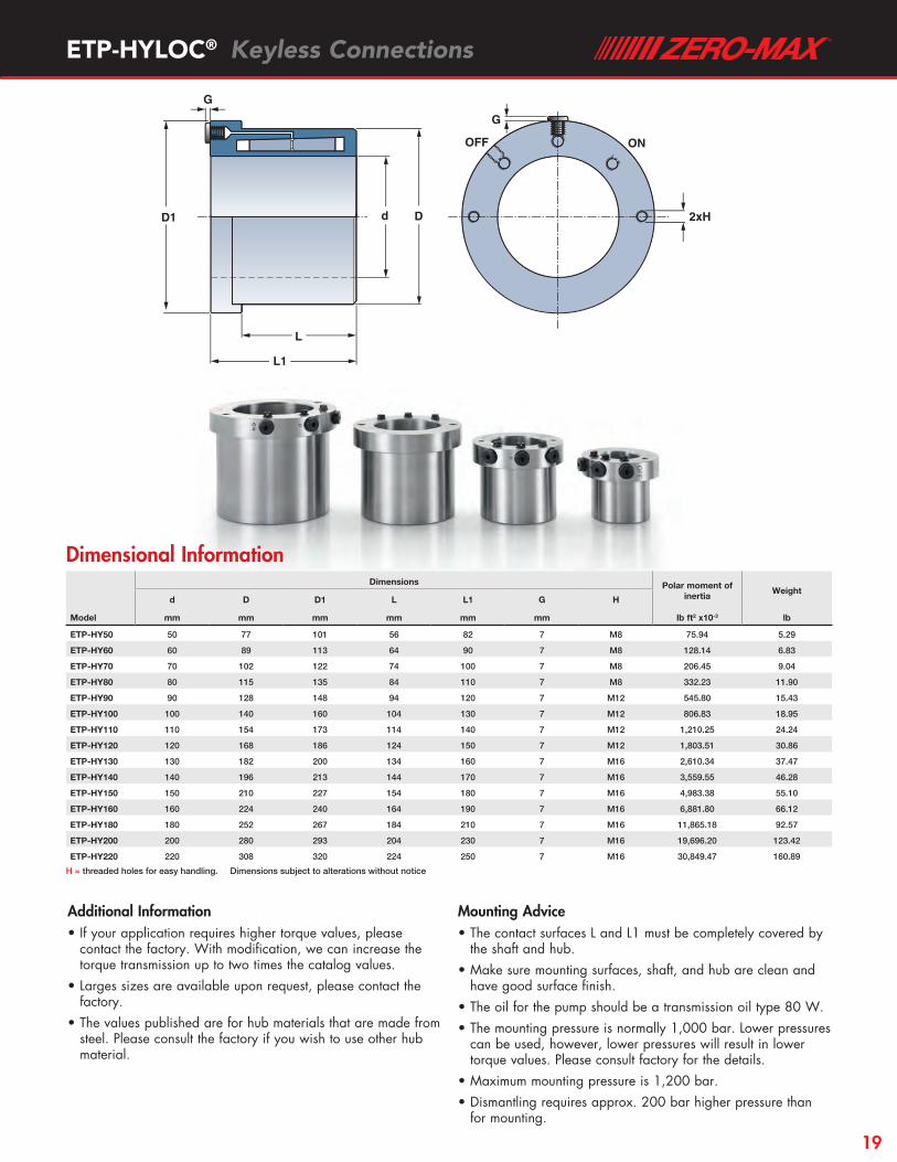
Dimensional InformationDimensions Polar moment of
inertiaWeight
d D D1 L L1 G H
Model mm mm mm mm mm mm lb ft2 x10-3 lb
ETP-HY50 50 77 101 56 82 7 M8 75.94 5.29
ETP-HY60 60 89 113 64 90 7 M8 128.14 6.83
ETP-HY70 70 102 122 74 100 7 M8 206.45 9.04
ETP-HY80 80 115 135 84 110 7 M8 332.23 11.90
ETP-HY90 90 128 148 94 120 7 M12 545.80 15.43
ETP-HY100 100 140 160 104 130 7 M12 806.83 18.95
ETP-HY110 110 154 173 114 140 7 M12 1,210.25 24.24
ETP-HY120 120 168 186 124 150 7 M12 1,803.51 30.86
ETP-HY130 130 182 200 134 160 7 M16 2,610.34 37.47
ETP-HY140 140 196 213 144 170 7 M16 3,559.55 46.28
ETP-HY150 150 210 227 154 180 7 M16 4,983.38 55.10
ETP-HY160 160 224 240 164 190 7 M16 6,881.80 66.12
ETP-HY180 180 252 267 184 210 7 M16 11,865.18 92.57
ETP-HY200 200 280 293 204 230 7 M16 19,696.20 123.42
ETP-HY220 220 308 320 224 250 7 M16 30,849.47 160.89
H = threaded holes for easy handling. Dimensions subject to alterations without notice
Additional Information• If your application requires higher torque values, please
contact the factory. With modification, we can increase the torque transmission up to two times the catalog values.
• Larges sizes are available upon request, please contact the factory.
• The values published are for hub materials that are made from steel. Please consult the factory if you wish to use other hub material.
Mounting Advice• The contact surfaces L and L1 must be completely covered by
the shaft and hub. • Make sure mounting surfaces, shaft, and hub are clean and
have good surface finish.• The oil for the pump should be a transmission oil type 80 W. • The mounting pressure is normally 1,000 bar. Lower pressures
can be used, however, lower pressures will result in lower torque values. Please consult factory for the details.
• Maximum mounting pressure is 1,200 bar. • Dismantling requires approx. 200 bar higher pressure than
for mounting.
19

zero-max.com
Transmittable Bore Tolerance Shaft Tolerance
T FA Upper Limit Lower Limit Grade Upper Limit Lower Limit Grade
Model lb ft lbf mm mm mm mm
ETP-HP160 2,139 6,969 187.046 – 187.000 H7 160.000 – 159.960 h7
ETP-HP180 3,393 9,846 210.046 – 210.000 H7 180.000 – 179.960 h7
ETP-HP200 4,720 12,297 234.046 – 234.000 H7 200.000 – 199.954 h7
ETP-HP220 6,711 15,916 257.052 – 257.000 H7 220.000 – 219.954 h7
ETP-HP240 8,850 19,625 275.052 – 275.000 H7 240.000 – 239.954 h7
ETP-HP260 11,800 24,054 298.052 – 298.000 H7 260.000 – 259.948 h7
ETP-HP280 15,488 29,224 323.057 – 323.000 H7 280.000 – 279.948 h7
ETP-HP300 19,913 35,968 338.057 – 338.000 H7 300.000 – 299.948 h7
Dimensions
d D D1 D2 L L1
Model mm mm mm mm mm mm
ETP-HP160 160 187 235 203 125 160
ETP-HP180 180 210 256 225 145 180
ETP-HP200 200 234 278 247 165 200
ETP-HP220 220 257 300 268 185 220
ETP-HP240 240 275 319 287 205 240
ETP-HP260 260 298 340 309 225 260
ETP-HP280 280 323 364 332 245 280
ETP-HP300 300 338 380 349 264 300
LL1
D1 Dd
3x M12
D2
FEATURES• Variable transmittable torque or axial force by
changing the mounting pressure.
• Easy mounting/dismantling of large components in tight spaces.
• Quick mounting. Only a grease pump is necessary for mounting.
• Radial and axial connection is possible.
• Fine adjustments of the hub can be made when mounting.
• Good concentricity even after several mountings.
ETP-HYDROPRESS® Keyless Connections
T = Transmittable torque when axial force is 0. FA = Transmittable axial force when torque is 0. Transmittable torque and axial force are based on a mounting pressure of 600 bar/8,700 psi.
Dimensional Information
Performance Information
DESIGN ETP-HYDROPRESS is a hydraulic joint which consists of a double-walled steel sleeve. A hydraulic grease pump is required for mounting.
OPERATION When the hydraulic pressure from the pump is injected into the ETP-HYDROPRESS the double walled sleeve expands the inner and outer wall of the connection creating a rigid friction joint.
20

ETP-KN® Knife Holder | ETP-UNIGRIP®
ETP-KN® Knife Holder FEATURES• Extremely fast mounting/dismantling with only one screw.• Can be mounted/dismantled 1000´s of times.• Extremely good concentricity, ≤0.006 mm, even after several
mountings.• Radial tightening of the screw saves space along the shaft.• Accurate positioning, no axial movement when mounting.
DESIGN ETP-KN is designed to expand only against the shaft and is used for fasten ing circular knives for slitting thin steel plates when manufacturing beverage and food cans. ETP-KN is only made to customer’s specification. Shaft dimensions 50 – 200 mm.
OPERATION When the actuation screw is tightened, the double-walled sleeve expands uniformly against shaft and creates a rigid friction joint. Dismantling is done by loosening the screw which returns the ETP-KN to its original dimensions. It can then easily be dismantled.
ETP-UNIGRIP® ETP-UNIGRIP is an axial tensioner used, for example, in the clamping of workpieces and tools against a shoulder on the shaft.ETP-UNIGRIP has two separate hydraulic functions. When tightening the screw (R), ETP-UNIGRIP grips to the shaft. When tightening screw, (A), 3 pistons are pressurized which creates a high axial force (20 kN) against the components which are going to be clamped.ETP-UNIGRIP is available in a limited range of standard sizes for shafts 35 – 65 mm. More information can be sent on request. Special versions also with threaded inner diameter can be offered.
21
zero-max.comCustomized Designed Keyless Connections
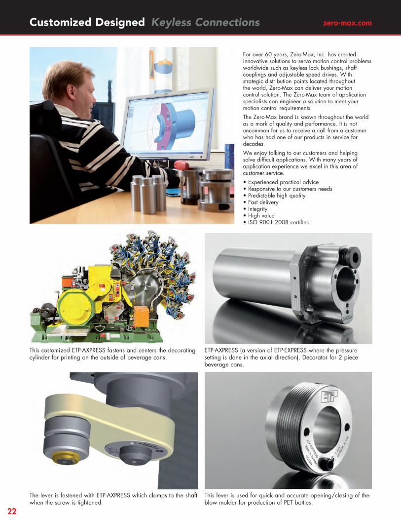
For over 60 years, Zero-Max, Inc. has created innovative solutions to servo motion control problems worldwide such as keyless lock bushings, shaft couplings and adjustable speed drives. With strategic distribution points located throughout the world, Zero-Max can deliver your motion control solution. The Zero-Max team of application specialists can engineer a solution to meet your motion control requirements.
The Zero-Max brand is known throughout the world as a mark of quality and performance. It is not uncommon for us to receive a call from a customer who has had one of our products in service for decades.
We enjoy talking to our customers and helping solve difficult applications. With many years of application experience we excel in this area of customer service.
• Experienced practical advice • Responsive to our customers needs • Predictable high quality • Fast delivery • Integrity • High value • ISO 9001:2008 certified
This customized ETP-AXPRESS fastens and centers the decorating cylinder for printing on the outside of beverage cans.
ETP-AXPRESS (a version of ETP-EXPRESS where the pressure setting is done in the axial direction). Decorator for 2 piece beverage cans.
The lever is fastened with ETP-AXPRESS which clamps to the shaft when the screw is tightened.
This lever is used for quick and accurate opening/closing of the blow molder for production of PET bottles.
22

Customized Designed Keyless Connections
Some customers tested the ETP solution for a few years, before finally the manufacturer started to use it for new machines.
Complete blow mold unit with several molds/cavities.
ETP-HYCON is a hydromechanical coupling used in the steel/paper or other heavy industries where the requirements are for high performance, compact design, low weight, low inertia, high rigidity and reduced down time for maintenances.
ETP-OCTOPUS is used to lock machine parts that need to be repositioned frequently. Linear repositioning can be done frequently with high precision along the shaft. Actuation is done with an external pressure source.
This ETP-EXPRESS R is made of high grade stainless steel, because it is washed regularly with an aggressive cleaning fluid.
Lever fastened with ETP-EXPRESS to open/close the mold.
23

zero-max.comTechnical Information
300
200
100 di /d0.1 0.3 0.5 0.7
ReL (N/mm2)
Because of the even and reasonable surface pressure and the compact built-in dimensions of the ETP connections, a thin material for the hub and shaft can be used. Also aluminium is possible.For hubs and hollow shafts in steel, the yield point of those materials decides the minimum thickness of the material. For cast iron and aluminium, the module of elasticity is decisive.The requisite thickness can be selected from the below table or more accurately in the diagram. NOTE: This information is not valid for ETP-HYLOC or ETP-OCTOPUS.
ReL = Yield point for the material. E = Module of elasticity. DH = The minimum outer diameter of the hub. di = The maximum inner diameter of the hollow shaft.
If DH/D < 1.4 for the hub or if di/d > 0.6 for the hollow shaft, contact us for advice. For all materials there will be an elastic expansion/ compression of the hub/hollow shaft.The expansion/compression will not be uniform of the hub/hollow shaft if the material is unsymmetrical. For accurate calculation contact us.
Dimensioning of Hubs and Hollow Shafts
Hub Hollow ShaftMaterial d i /d
Steel incl. stainless, ReL > 300 N/mm2 0.6
Steel incl. stainless, ReL > 240 N/mm2 0.5
Cast iron, E=120 kN/mm2 0.3
Aluminium, E=70 kN/mm2 0.2
Material D H /D
Steel incl. stainless, ReL > 300 N/mm2 1.4
Steel incl. stainless, ReL > 220 N/mm2 1.5
Cast iron, E=120 kN/mm2 2.0
Aluminium, E=70 kN/mm2 2.5
100
0 DH/D
ReL (N/mm2)
300
200
1.0 1.4 1.8 2.21.2 1.6 2.0 2.4
Ls DHdi d D
Built-in principle of an ETP-connection.The ETP connections are tubular and create a surface pressure on to the shaft and the hub. Through the friction resistance both axial forces and torques can be transmitted. The amount will be determined by the area of the contact length (Ls), the surface pressure and the coefficient of friction (µ).
LS = the contact length. p = surface pressure on the shaft.
T = p • • Ls • µπd2
2
When the loads are in form of alternating or pulsating torque it is recommended to reduce the transmittable torque rating, T. For further information see technical specification sheet for corresponding product.
Transmittable Torque
The following formula is valid:
Alternating Load
Torq
ue
-1
0
1
Pulsating Load
Torq
ue
0
1
24

Technical Information
Recommended Surface Finish, Shaft/HubRa max 3.0 (µm) Ra min 1.0 (µm)
The coefficient of friction depends on a number of factors. The most important are:
SURFACE FINISHThe surface must not be too smooth. If it is, the influence of impurities can be significant. A good turning operation is often better than grinding.
CLEANLINESSIt is very important that the surfaces are well cleaned. Grease on the surfaces will drastically reduce the coefficient of friction.A thin oil will, however, only reduce the coefficient of friction by about 0.03 µ.
Coefficient of Friction (µ)
If the surface pressure is too low, a metallic contact between the surfaces will not be created because of oxide layers. If the surface pressure is too high, plastic deformation can occur and the friction will decrease dramatically. The hydraulic ETP principle gives a surface pressure within the right range, which is also even around and along the entire contact area.The surface pressure from the ETP connections (not ETP-HYLOC) at the recommended tightening torque is approximately 80 N/mm2.
Surface Pressure
The hydraulic ETP principle assures a good runout and balance. All products are balanced by design. For guide values see the table.To these values the runout/unbalance for shaft and hub in the actual case has to be added in order to get the final value when mounted.Balancing can be done on request.ETP-EXPRESS and ETP-TECHNO upon request can be dynamically balanced to G 2.5, at a requested rpm.
Runout and Balance
* Values are also valid after repeated mountings.** For size ≤ 100 mm, with radial mounted steel plugs, the unbalance is larger.
MaterialETP-EXPRESS
incl. type R and CETP-TECHNO ETP-POWER
ETP-CLASSIC incl. type R
ETP-MINI incl. type R
ETP-HYLOC
Runout (mm)*
≤ 0.02 ≤ 0.006 ≤ 0.03 0.03 – 0.06 ≤ 0.02 ≤ 0.02
Unbalance (gmm/kg) 75 50 75 100 100 75**
If there is a keyway in the shaft or hub, we recommend it to be filled in with, for example, some two component hardening medium (not needed for ETP-MINI). The medium should then be ground to the diameter of the shaft/hub. This prevents deformation and dismantling problems of the double-walled sleeve.
Keyways
One of the qualities with the ETP connections are their ability to be mounted quickly and repeatedly with maintained performance and precision.There is, however, a limit when the screw/screws will be worn and have to be changed. If the threads are cleaned and regularly lubricated, the guide values in the table can be used.The values indicate when the screw needs to be changed allowing the ETP connection to last longer.For the R types it is very important that the screws are well lubricated when tightening, both for proper function and full lifetime capabilities. When used in food processing applications or similar we recommend the lubricant Molykote P-1900. For other applications Molykote G-n plus can be used.ETP-HYLOC is not recommended for more than 2,000 mountings.
Number of Mountings ETP Connection Number of mountings
ETP-EXPRESS 15-35 2,000
ETP-EXPRESS 38-60 1,000
ETP-EXPRESS 70-100 500
ETP-EXPRESS R 15-35 800
ETP-EXPRESS R 38-60 400
ETP-EXPRESS R 70-80 200
ETP-TECHNO 15-45 5,000
ETP-TECHNO 50-75 3,000
ETP-TECHNO 80-130 500
ETP-POWER 15-30 500
ETP-POWER 32-40 200
ETP-CLASSIC 100
ETP-CLASSIC R 50
ETP-MINI 100
ETP-MINI R 50
ETP-HYLOC 2,000
25
zero-max.comTechnical Information
0
10
20
30
40
50
60
70
10 20 30 40 50 60 70 80 90 100 110 120 130mm, shaft
FA kN
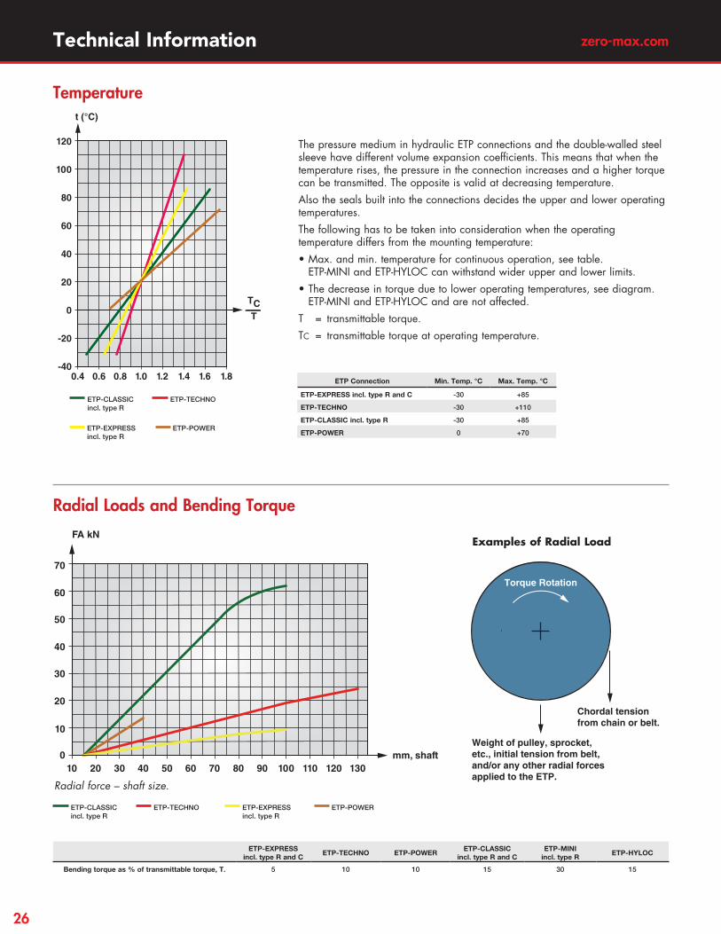
Radial force – shaft size.
Radial Loads and Bending Torque
ETP-EXPRESS incl. type R and C
ETP-TECHNO ETP-POWERETP-CLASSIC
incl. type R and CETP-MINI
incl. type RETP-HYLOC
Bending torque as % of transmittable torque, T. 5 10 10 15 30 15
ETP-TECHNO ETP-EXPRESSincl. type R
ETP-CLASSICincl. type R
ETP-POWER
The pressure medium in hydraulic ETP connections and the double-walled steel sleeve have different volume expansion coefficients. This means that when the temperature rises, the pressure in the connection increases and a higher torque can be transmitted. The opposite is valid at decreasing temperature. Also the seals built into the connections decides the upper and lower operating temperatures.The following has to be taken into consideration when the operating temperature differs from the mounting temperature:• Max. and min. temperature for continuous operation, see table.
ETP-MINI and ETP-HYLOC can withstand wider upper and lower limits.• The decrease in torque due to lower operating temperatures, see diagram.
ETP-MINI and ETP-HYLOC and are not affected.T = transmittable torque.TC = transmittable torque at operating temperature.
t (°C)
120
100
80
60
40
20
0
-20
-40 0.4 0.6 0.8 1.0 1.2 1.4 1.6 1.8
TCT
Temperature
ETP Connection Min. Temp. °C Max. Temp. °C
ETP-EXPRESS incl. type R and C -30 +85
ETP-TECHNO -30 +110
ETP-CLASSIC incl. type R -30 +85
ETP-POWER 0 +70
ETP-TECHNO ETP-CLASSICincl. type R
ETP-EXPRESSincl. type R
ETP-POWER
Weight of pulley, sprocket, etc., initial tension from belt, and/or any other radial forces applied to the ETP.
Torque Rotation
Chordal tension from chain or belt.
Examples of Radial Load
26

Technical Information
Due to centrifugal force, the transmittable torque will be reduced with increasing speed (rpm). The diagram gives examples for ETP-TECHNO 50 with a steel hub. A reduced tolerance between the contact surfaces gives a higher surface pressure at the same tightening torque, and thus higher transmittable torque at high speeds. A thicker hub is more effected by the centrifugal force and the torque will reduce faster at increasing speed. The example is not directly applicable for other sizes or types of ETP connections. Contact us for assistance with calculations at high speeds.
Torque and Speed
400
800
1,200
1,600
2,000
2,400
2,800
3,200
5,000 10,000 15,000 20,000 25,000 30,0000
Nm
rpm
ETP-TECHNO 50Min tol. DH/D=1.4
ETP-TECHNO 50Max tol. DH/D=2
ETP-TECHNO 50Max tol. DH/D=1.4
Most friction joints have limited capacity to transmit radial forces and bending torque. High levels of these loads can affect the function of the ETP connection. The values acc. to the diagram and table based on tests can serve as guide lines. ETP-MINI and ETP-HYLOC can transmit higher radial forces than the other connections.
Design Tip
ETP-TECHNO gives advantages when used to fasten printing cylinders in light materials, for example aluminium. The cylinder can be changed 1,000s of times, using the same ETP-TECHNO, with maintained good concentricity and repeatability. The radial access to the screw facilitates the handling and saves space.
Design Tip
When manufacturing precision gears, they can be fastened with ETP- EXPRESS. If the gear is fi xed in its position with an axial screw or pin before the last grinding operation, a repeatability within 2 µm will be achieved.
Design Tip
P2 P1
At varying temperature and with a hub made from aluminium ETP-connections can be used. Because of the even surface pressure and the lack of slotted sleeves, ETP-connections can function as a sealing element up to a pressure difference, p1 – p2, of 50 bar.
Design Tip
If an axial force (F1) and a torque (T1) are to be transmitted at the same time, the following formula is valid.
FA and T are the rated values for axial force and torque for the different ETP products.
0 0.5 1T1T
0.5
0.87
1
F1FA
Axial Force
F1
FA( ) T1
T( )+2 2
≤ 1 this means that the value should be inside the quarter circle in the diagram.
Design Tips
27
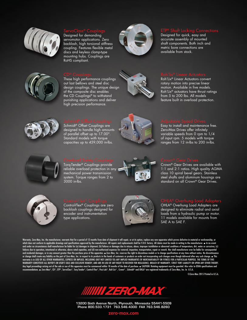
ServoClass® CouplingsDesigned for demanding servomotor applications. Zero backlash, high torsional stiffness coupling. Features flexible metal discs and keyless clamp-type mounting hubs. Couplings are RoHS compliant.
Schmidt® Offset CouplingsSchmidt® Offset Couplings are designed to handle high amounts of parallel offset up to 17.00". Standard models with torque capacities up to 459,000 in-lbs.
Overload Safety CouplingsTorq-Tender® Couplings provide reliable overload protection in any mechanical power transmission system. Torque ranges from 2 to 3000 in-lbs.
ETP® Shaft Locking ConnectionsDesigned for quick, easy and accurate assembly of mounted shaft components. Both inch and metric bore connections are available from stock.
Adjustable Speed DrivesEasy to install and maintenance free. Zero-Max Drives offer infinitely variable speeds from 0 rpm to 1/4 of input rpm. 5 models with torque ranges from 12 in-lbs to 200 in-lbs.
Crown® Gear DrivesCrown® Gear Drives are available with 1:1 and 2:1 ratios. High quality AGMA class 10 spiral bevel gears. Stainless steel shafts and aluminum housings are standard on all Crown® Gear Drives.
Roh’lix® Linear ActuatorsRoh’Lix® Linear Actuators convert rotary motion into precise linear motion. Available in five models. Roh’Lix® actuators have thrust ratings from 5 to 200 lbs. All models feature built in overload protection.
CD® CouplingsThese high performance couplings out last bellows and steel disc design couplings. The unique design of the composite disc enables the CD Couplings® to withstand punishing applications and deliver high precision performance.
Control-Flex® CouplingsControl-Flex® Couplings are zero backlash couplings designed for encoder and instrumentation type applications.
OHLA® Overhung Load AdaptersOHLA® Overhung Load Adapters are designed to eliminate radial and axial loads from a hydraulic pump or motor. 11 models available for mounts from SAE A to SAE F.
Warranty. Zero-Max, Inc. the manufacturer, warrants that for a period of 12 months from date of shipment it will repair, or at its option, replace any new apparatus which proves defective in material or workmanship, or which does not conform to applicable drawings and specifications approved by the manufacturer. All repairs and replacements shall be F.O.B. factory. All claims must be made in writing to the manufacturer. • In no event and under no circumstances shall manufacturer be liable for (a) damages in shipment; (b) failures or damages due to misuse, abuse, improper installation or abnormal conditions of temperature, dirt, water or corrosives; (c) failures due to operation, intentional or otherwise, above rated capacities, and (d) non-authorized expenses for removal, inspection, transportation, repair or rework. Nor shall manufacturer ever be liable for consequential and incidental damages, or in any amount greater than the purchase price of the apparatus. • Zero Max, Inc. reserves the right to discontinue models or to change specifications at any time without notice. No discontinuance or change shall create any liability on the part of Zero-Max, Inc. in respect to its products in the hands of customers or products on order not incorporating such changes even though delivered after any such change. • This warranty is in LIEU OF ALL OTHER WARRANTIES, EXPRESS OR IMPLIED, INCLUDING (BUT NOT LIMITED TO) ANY IMPLIED WARRANTIES OF MERCHANTABILITY OR FITNESS FOR A PARTICULAR PURPOSE. THE TERMS OF THIS WARRANTY CONSTITUTE ALL BUYER’S OR USER’S SOLE AND EXCLUSIVE REMEDY, AND ARE IN LIEU OF ANY RIGHT TO RECOVER FOR NEGLIGENCE, BREACH OF WARRANTY, STRICT TORT LIABILITY OR UPON ANY OTHER THEORY. Any legal proceedings arising out of the sale or use of this apparatus must be commenced within 18 months of the date of purchase. • CAUTION: Rotating equipment must be guarded. Also refer to OSHA specifications and recommendations. • Zero-Max®, CD®, ETP®, ServoClass®, Torq-Tender®, Control-Flex®, Posi-Lok®, Roh’Lix® , Crown® , Schmidt® and OHLA® are registered trademarks of Zero-Max, Inc. In U.S.A.
©Zero-Max 2015 Printed in U.S.A.
13200 Sixth Avenue North, Plymouth, Minnesota 55441-5509Phone 800.533.1731 763.546.4300 FAX 763.546.8260
zero-max.com