ke-265 keyless entry system installation and instruction
TRANSCRIPT

Essex Electronics, Inc. | 805.684.7601 | 800.KEY-LESS | fax 805.684.0232 | keyless.com
INSTALLATION & INSTRUCTION MANUAL
Keyless Entry® Access Control System
KE-265

Essex Electronics, Inc. | 805.684.7601 | 800.KEY-LESS | fax 805.684.0232 | keyless.comi
All rights reserved. No part of this documentation may be reproduced in any form, without prior written consent of Essex Electronics, Inc. Essex Electronics shall not be liable for errors contained in this manual. The information in this document is subject to change without notice. Essex Electronics, Inc. reserves the right to modify this documentation and to make improvements or changes to the product(s) contained in this documentation at any time.
Document Information IOMKE265.0514.Rev G Installation/Operations Manual for KE-265, May 2014, Revision G. This documentation is applicable to the KE-265 with CM-265-SL on the date code label. (Located on the control module circuit board). This documentation is also applicable to prior revisions except where noted.
Trademarks Keyless Entry® is a registered trademark of Essex Electronics, Inc. Lexan® is a registered trademark of General Electric Co., USA.
Contact Information Essex Electronics, Incorporated 1130 Mark Avenue, Carpinteria, CA 93013 (805) 684-7601 or (800) 539-5377 (KEY-LESS) FAX (805) 684-0232
Website: keyless.com General email: [email protected] Technical Support email: [email protected]
Copyright© 2001-2014 Essex Electronics, Inc. All rights reserved.
KE-265 Keyless Entry® Access Control System

Essex Electronics, Inc. | 805.684.7601 | 800.KEY-LESS | fax 805.684.0232 | keyless.com ii
Introduction .....................................................................................1 Overview...........................................................................................1 System Specifications ......................................................................1 Input Requirements ..........................................................................2 Output Capabilities ...........................................................................3 Keypad Options ................................................................................4 Keypad Part Numbers ......................................................................4Preparing For Installation ..............................................................5 System Components ........................................................................5The Installation Procedure ............................................................6 Required Tools ..................................................................................6 Prepare the Keypad for Installation ..................................................6 Install the Wiring Cable.....................................................................8 Mount the Keypad ............................................................................8 Prepare the Door for the Electric Strike ............................................9 Installing the Control Module ............................................................9 Connecting the Locking Device ......................................................10 Battery Backup ...............................................................................10System Hardware Setup ..............................................................11 Remote By-Pass.............................................................................11 Anti-Tailgating .................................................................................11 Setting Relay Options .....................................................................11 Tamper Alarm Lockout ....................................................................15System Programming ..................................................................16 Overview of System Code Programming .......................................16 Overview of the Master Code .........................................................16 Programming the Master Code ......................................................17 Overview of User Codes.................................................................17 Programming User Codes ..............................................................18 Programming Door Open Time.......................................................19Troubleshooting ...........................................................................21Notes..............................................................................................24Repairs and Warranty ..................................................................26Appendix A - Circuit Board Layout .............................................30Appendix B - Typical Wiring Diagrams .......................................31
Table of Contents

Essex Electronics, Inc. | 805.684.7601 | 800.KEY-LESS | fax 805.684.0232 | keyless.comiii

1Essex Electronics, Inc. | 805.684.7601 | 800.KEY-LESS | fax 805.684.0232 | keyless.com
Introduction Overview – The KE-265 SeriesThe KE-265 is an easy to program, easy to use, stand-alone Keyless Entry® system with features suitable for basic access control requirements. Providing either a voltage output or dry contact closure, the KE-265 is designed to control any fail-safe or fail-secure electric locking device.
The KE-265 features one master code and five user codes. Two relay outputs are available to provide a variety of access control configurations including single door operation with an auxiliary output for a CCTV/Light Controller, a Gate/Garage Door controller or Doorbell activation or the KE-265 can be configured for two door operation.
Input Requirements: 12 to 24V AC/DCStandby Current Draw: 12V a 10 mA
24V a 25 mAOutputs: 2 SPDT Relay contacts at 6 amps
(120VAC); Voltage or Dry Contact; Fail Safe or Fail Secure Relay Configuration
Programmable Output 1 to 120 seconds(Door Open Time): Default a 5 secondsLatching: Manual (Toggle On/Off)# of User Codes: 6 Codes (1 Master, 5 User)Code Length: 3 to 8 DigitsDefault Master Code: 1-3-5-7-9
System Specifications
Essex Electronics, Inc. | 805.684.7601 | 800.KEY-LESS | fax 805.684.0232 | keyless.com2
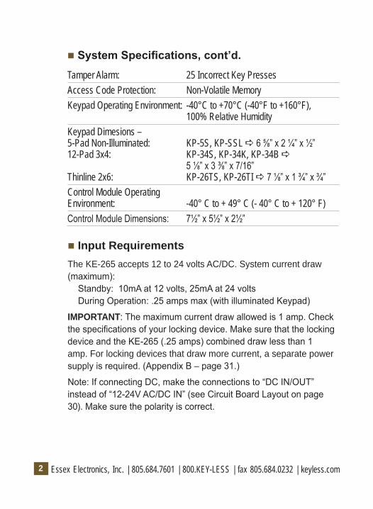
Tamper Alarm: 25 Incorrect Key PressesAccess Code Protection: Non-Volatile MemoryKeypad Operating Environment: -40°C to +70°C (-40°F to +160°F),
100% Relative HumidityKeypad Dimesions –5-Pad Non-Illuminated: KP-5S, KP-SSL a 6 ⅝” x 2 ¼” x ½”12-Pad 3x4: KP-34S, KP-34K, KP-34B a
5 ⅛” x 3 ⅜” x 7/16”Thinline 2x6: KP-26TS, KP-26TI a 7 ⅛” x 1 ¾” x ¾”Control Module Operating Environment: -40° C to + 49° C (- 40° C to + 120° F)Control Module Dimensions: 7½” x 5½” x 2½”
System Specifications, cont’d.
Input RequirementsThe KE-265 accepts 12 to 24 volts AC/DC. System current draw (maximum): Standby: 10mA at 12 volts, 25mA at 24 volts During Operation: .25 amps max (with illuminated Keypad)
IMPORTANT: The maximum current draw allowed is 1 amp. Check the specifications of your locking device. Make sure that the locking device and the KE-265 (.25 amps) combined draw less than 1 amp. For locking devices that draw more current, a separate power supply is required. (Appendix B – page 31.)
Note: If connecting DC, make the connections to “DC IN/OUT” instead of “12-24V AC/DC IN” (see Circuit Board Layout on page 30). Make sure the polarity is correct.

3Essex Electronics, Inc. | 805.684.7601 | 800.KEY-LESS | fax 805.684.0232 | keyless.com
Output CapabilitiesThe KE-265 provides two SPDT dry contact relays (rated at 6 amps at 120 VAC). Each relay can be configured to perform one of many different functions depending on the specific access control requirement. User Authorization to control each relay is determined by Setting Relay Options (see System Hardware Setup on page 11). Each relay can be configured for one of the following options:
1. Voltage Output – For any Fail Safe or Fail Secure Locking Device
2. Dry Contact Output – For control of Gate Operator or Garage Door.
3. CCTV or Light Controller – First key press triggers a 10 second output.
4. Doorbell – Press * at the Keypad to trigger a 1 second output for a doorbell (not included). This function is only available with a 12 Pad 3x4 or Thinline 2x6.
5. Auxiliary Output – Momentary or Manual Control of an electronic device.
Essex Electronics, Inc. | 805.684.7601 | 800.KEY-LESS | fax 805.684.0232 | keyless.com4
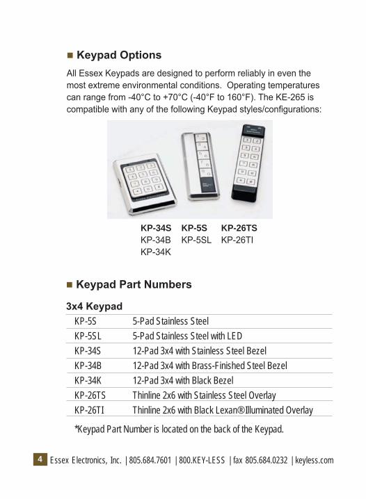
Keypad OptionsAll Essex Keypads are designed to perform reliably in even the most extreme environmental conditions. Operating temperatures can range from -40°C to +70°C (-40°F to 160°F). The KE-265 is compatible with any of the following Keypad styles/configurations:
Keypad Part Numbers
3x4 KeypadKP-5S 5-Pad Stainless SteelKP-5SL 5-Pad Stainless Steel with LEDKP-34S 12-Pad 3x4 with Stainless Steel BezelKP-34B 12-Pad 3x4 with Brass-Finished Steel BezelKP-34K 12-Pad 3x4 with Black BezelKP-26TS Thinline 2x6 with Stainless Steel OverlayKP-26TI Thinline 2x6 with Black Lexan® Illuminated Overlay
*Keypad Part Number is located on the back of the Keypad.
KP-34S KP-5S KP-26TSKP-34B KP-5SL KP-26TIKP-34K

5Essex Electronics, Inc. | 805.684.7601 | 800.KEY-LESS | fax 805.684.0232 | keyless.com
Preparing For Installation System ComponentsThere are four primary components to be installed:
1. The Keypad should be mounted on the wall adjacent to the door. It should be on the same side as the door strike and about 4 feet above the floor.
2. The Control Module should be mounted inside the building near a power source. Typically the control module is hidden in a false ceiling or closet. The control module must be located in an environmentally controlled area where the temperature remains between -40°C and +49°C (-40° F and 125° F).
3. The Wiring Cable connects the keypad to the control module. It is important not to locate the cable adjacent to any wiring that carries line voltage. Included with the system is a 15-foot CL2 12 conductor jacketed wiring cable of which only 11 wires are used. If the Control Module must be located further than 15 feet from the Keypad, additional cable may be spliced. The maximum distance between the Keypad and the Control Module must not exceed 1,000 feet. For runs over 200 feet, 18 gauge wire should be used. Under 200 feet, 20 gauge is acceptable.
4. The Electric Strike/Other Locking Device (not included) connects to the KE-265’s Main Relay output via a strike cable. (Appendix B – Typical Wiring Diagrams – page 31.)
Typical Installation

Essex Electronics, Inc. | 805.684.7601 | 800.KEY-LESS | fax 805.684.0232 | keyless.com6
The Installation Procedure Required ToolsYou will need the following tools:
Medium-size, Phillips head screwdriver 1/8” standard screwdriver Drill 7/8” or 1” (25mm) drill bit 1/2” (16mm) drill bit 5/32” (4mm) drill bit (For 12-Pad 3x4) 3/16” (6mm) drill bit (For 5-Pads & Thinline 2x6)
Prepare the Keypad for InstallationThere are different procedures for mounting each Keypad. Locate the Keypad part number on the back of the Keypad and follow appropriate mounting instructions below. Keypad templates are included with each Keypad (except KP-34’s) to assist with the installation.
Mounting Instructions 5 Pad Non Illuminated: KP-5S and KP-5SL1. Select flat mounting surface 3” X 7”.
2. Use “Template A” (included with the Keypad) to mark locations of holes A, B, and C.
3. Locate and drill the large hole marked “A”. Hole must be at least 7/8” (22mm) diameter.
4. Hold the Keypad against the wall with the connector through hole “A”. Check markings for hole “B”. Re-mark if required. If using plastic anchors, drill hole “B” using 3/16” (6mm) bit. NOTE: Plastic anchors are provided for some mounting applications. If anchors are not used, holes “B” and “C” must be smaller than 3/16”.
7Essex Electronics, Inc. | 805.684.7601 | 800.KEY-LESS | fax 805.684.0232 | keyless.com
5. Using the template, verify the hole marked “C” is aligned and then drill hole “C”.
6. Install the metal mounting bracket into hole “C” with the screw provided.
7. Do NOT mount Keypad at this time.
8. Proceed to Install the Wiring Cable.
Mounting Instructions 12 Pad 3x4: KP-34S, KP-34B or KP-34KThe 3x4 keypad is designed to mount to a single gang switchbox or on a wall, pedestal or any flat surface of at least 3 ½ by 5 ¼”. The composition of the mounting surface will determine the fastening method required. If mounting to a surface other than a switchbox:
1. Select a flat surface (3 ½” by 5 ¼”) near the door where you wish to install the keypad.
2. Drill the large hole for the Keypad connector using a 7/8” (25mm) drill bit.
3. Place the connector on the back of the keypad in the large hole. Mark the keypad mounting holes.
4. Drill clearance holes in accordance with fastening method used. (If mounting to wood, drill small pilot holes and use #6 flat head wood screws provided. If mounting to metal, drill two 5/32” clearance holes for #6 flat head machine screws provided.)
5. Do NOT mount the keypad at this time.
6. Proceed to Install the Wiring Cable.
Mounting Instructions Thinline 2x6: KP-26TS and KP-26TIThe Thinline 2x6 is designed for mullion mount applications. It can also be mounted on a wall, pedestal or any flat surface of at least 1 ¾” by 7”. The composition of the mounting surface will determine the fastening method required:
Essex Electronics, Inc. | 805.684.7601 | 800.KEY-LESS | fax 805.684.0232 | keyless.com8
1. Select a flat surface (1 ¾” by 7”) near the door where you wish to install the keypad.
2. Using the Thinline template, mark location of holes.
3. Drill the large hole using a 1” (25mm) drill bit.
4. Place the connector on the back of the keypad in the large hole to verify that the mounting holes are aligned. Make adjustments if necessary.
5. Drill mounting holes in accordance with fastening method used. If mounting to wood, drill small pilot holes and use #6 flat head wood screws provided. If mounting to metal, drill two 5/32” clearance holes for #6 flat head machine screws provided.
6. Do NOT mount the keypad at this time.
7. Proceed to Install the Wiring Cable.
Install the Wiring Cable
1. Drill a ½” hole in the inside wall or ceiling where you want the cable to come through.
2. Pull the cable through the hole so the connector end goes to the keypad. Route it so there is minimal cable at the keypad.
Note: Supplied with the system is a 12-conductor cable designed to connect the keypad to the control module. You will also need a three-conductor cable (not included) to connect the control module to the electric strike or other locking device.
Mount the Keypad
1. Attach the wiring connector to the Keypad. 2. Attach the Keypad to the wall. 3. Do NOT attach the Keypad labels until the system is tested.

9Essex Electronics, Inc. | 805.684.7601 | 800.KEY-LESS | fax 805.684.0232 | keyless.com
Prepare the Door for the Electric Strike
Follow these instructions only if you are using an electric strike to unlock the door. If you are using the main relay to activate a garage door, automatic gate, etc., skip this section. The new electric strike should be checked to verify compatibility with existing door hardware prior to installation.
1. Remove existing strike.
2. Follow directions included with the strike for preparing the doorjamb.
3. Do NOT mount the strike at this time.
Installing the Control Module
1. Connect the Wiring Cable to Terminal Strip “A” following the color sequence on the circuit board. (Appendix A – page 30.) NOTE: If the wiring cable has been cut shorter than 15 feet, the tan wire will become exposed. The tan wire is NOT used with the KE-265.
2. Connect 12 to 24 Volts AC to Terminal Strip “B” to screws marked “12-24V AC/DC IN”.
Note: If connecting DC, make the connections to “DC IN/OUT” instead of “12-24V AC/DC IN”. Make sure the polarity is correct.
IMPORTANT: The “EARTH” screw terminal on Terminal Strip “A” should be connected to a true earth ground for proper system protection and operation.

Essex Electronics, Inc. | 805.684.7601 | 800.KEY-LESS | fax 805.684.0232 | keyless.com10
Connecting the Locking Device
Connect the electric locking device to Terminal Strip “B” as outlined in the Typical Wiring Diagram (Appendix B – page 31). Any 3 conductor, 18 gauge wire can be used to connect the Control Module to the Locking Device. Included with each system are two MOV’s (metal oxide varistor). The function of the MOV is to absorb any inductive kickback from the locking device, protecting the circuit board. The MOV’s have been installed under the relay contact screws and can be left there for normal “FAIL SECURE” lock operation. For “FAIL SAFE” locks, move one leg from the “N.O.” screw to the “N.C.” screw (Appendix B – page 31). If possible, install the MOV closer to the electric lock. If switching voltages higher than 36V, remove the MOV. To provide proper grounding, connect the 3rd wire from the body of the locking device to the “EARTH” screw on Terminal “A.”
Battery Backup
Although battery backup is NOT required for User Code retention, you may wish to connect to a UPS (Uninterruptible Power Supply) to provide operation during a power interruption.

11Essex Electronics, Inc. | 805.684.7601 | 800.KEY-LESS | fax 805.684.0232 | keyless.com
System Hardware Setup Remote By-Pass
In some cases, it may be necessary to control the door from a remote area such as a security station or reception desk. The KE-265 provides for a Remote By-Pass/REX (Exit Switch) or Keypad override. This can be accomplished by connecting a normally open switch to the “REMOTE” screw terminals on the circuit board (Appendix A – page 30). When the Remote By-Pass switch is depressed, the contact bypasses the Keypad and activates the relay tied to “1, 2 UNLOCK” (see Setting Relay Options). The relay is activated for the same time length as the programmed Door Open Time (see Programming Door Open Time).
Anti-Tailgating
Some security applications require stricter door monitoring. Anti-tailgating can be accomplished by installing a normally closed door monitor switch to the “DOOR MONITOR” screw terminals on the circuit board (Appendix A). This switch may be the output of a latch monitor switch, a monitor maglock or an alarm switch that senses door movement. When this switch opens, it will relock the door. (Note: If a door monitor switch is NOT used, you must jump the “MONITOR” screw terminals with the factory installed wire.)
Setting Relay Options
The KE-265 provides a variety of options for configuring both relays. These options include User Unlock Authorization, Latching Authorization and CCTV/Doorbell setup. Configuring these options is accomplished by setting jumpers on the Control Module circuit board. To set relay options, first locate the relay jumpers (3 rows of 7 pins). Next to each set of three pins, there is a description of the

Essex Electronics, Inc. | 805.684.7601 | 800.KEY-LESS | fax 805.684.0232 | keyless.com12
option to be configured. Placing jumpers across the 1st & 2nd pins, the 2nd & 3rd pins or no pins at all determines how each option is configured.
To set an Option for Relay #1 a Place jumper across 2nd & 3rd pins.
To set an Option for Relay #2 a Place jumper across 1st & 2nd pins.
To set an Option for No Relay a Don’t place jumper across 1st & 2nd or 2nd & 3rd pins.
The Factory Default Settings are shown here:
1. All User Unlock Authorization is configured for Relay #1. (Master Code and Users 1,2 and Users 3,4,5).
2. No Code is set for Latching Authorization of either relay.
3. Neither CCTV nor DOORBELL is active.
User Unlock Authorization
Placing jumpers across the first 3 sets of pins (MASTER UNLOCK, 1,2 UNLOCK or 3,4,5 UNLOCK) determines which relay (if any) each User Group is authorized to activate.
When a valid code is entered, the door will remain unlocked for the programmed Door Open Time. (See Programming Door Open Time.)
Factory Default Settings
User Unlock Authorization

13Essex Electronics, Inc. | 805.684.7601 | 800.KEY-LESS | fax 805.684.0232 | keyless.com
Example:
1. Placing a jumper across the 2nd and 3rd pins of the “MASTER UNLOCK” option allows the master code to activate (unlock) Relay #1.
2. Placing a jumper across the 1st and 2nd pins of the “1,2 UNLOCK” option allows User Code 1 and User Code 2 to activate Relay #2.
3. Leaving a jumper off the “3,4,5 UNLOCK” option prevents User Code 3, User Code 4 and User Code 5 from activating either relay.
Latching Authorization
Placing jumpers across the 4th and 5th set of pins (1,2 LATCH or 3,4,5 LATCH) determines which relay (if any) each User Group is authorized to manually latch.
How to Latch
When a valid code is entered on the keypad followed by “7”, the Latch Authorization relay for that particular User Group will energize and remain energized until a valid code followed by “7” is entered again.
Example:
1. Placing a jumper across the 1st and 2nd pins of the “1, 2 LATCH” option allows User 1 and User 2 to Latch Relay #2.
2. Leaving a jumper off the “3,4,5 LATCH” option prevents User 3, User 4 and User 5 from latching either relay.
Note: Because the Master Code is primarily used to program User codes, the Master Code does not have Latching Authorization.
Latching Authorization

Essex Electronics, Inc. | 805.684.7601 | 800.KEY-LESS | fax 805.684.0232 | keyless.com14
CCTV/Doorbell Setup
Placing jumpers across the 6th or 7th set of pins (CCTV or DOORBELL) determines which relay (if any) will be used to activate a CCTV or Doorbell.
CCTV Operation: If either relay is configured to activate a CCTV, any key press on the Keypad triggers a 10 second output.
Doorbell Operation: If either relay is configured to activate a doorbell, pressing * at the Keypad triggers a 1 second output. (Doorbell only functions with 12-Pad 3x4 or Thinline 2x6)
2nd Door Operation
The KE-265 has been designed to provide 2 door operation with one or more Keypads. With this configuration, certain codes will activate Relay #1 and certain codes will activate Relay #2. (Connect Relay #2 to the 2nd Locking Device)
Example:
1. Placing a jumper across the 2nd and 3rd pins of the “MASTER UNLOCK” option allows the master code to activate (unlock) Relay #1.
2. Placing a jumper across the 2nd and 3rd pins of the “1,2 UNLOCK” option allows User Code 1 and User Code 2 to activate (unlock) Relay #1.
CCTV/Doorbell Setup
2nd Door Operation

15Essex Electronics, Inc. | 805.684.7601 | 800.KEY-LESS | fax 805.684.0232 | keyless.com
3. Placing a jumper across the 1st and 2nd pins of the “3,4,5 UNLOCK” option allows User Code 3, User Code 4 and User Code 5 to activate (unlock) Relay #2
4. In this example, User Code 1 and User Code 2 have also been given Latching Authorization for Relay #1.
Note: In order for 2 Door configuration to operate correctly, be sure to remove any jumpers across the CCTV option and the Doorbell option.
Tamper Alarm Lockout
A person attempting to gain entry by guessing the code and pushing 25 wrong digits will cause the KE-265 to go into tamper alarm mode. The Keypad will beep constantly for 30 seconds during which time the door will remain locked and no keypad functions can be performed.
Essex Electronics, Inc. | 805.684.7601 | 800.KEY-LESS | fax 805.684.0232 | keyless.com16
System Programming Overview of System Code ProgrammingThere are TWO levels of codes for the KE-265 system.
1. The Master Code (used to open the door and for programming User Codes)
2. User Codes (used by personnel to open the door)
IMPORTANT: Notes to remember before programming:
1. All codes must be 3 to 8 digits.
2. All codes must be different from each other. Note: 5-Pad Keypads have two digits on each pad. The system reads these numbers as the same. For example: 1-3-5-7-9 is the same as 2-4-6-8-0.
3. Do not program codes, which are part of other codes.
For example: User Code 1 a 1-2-3-4-5 and User Code 2 a 1-2-3
4. During programming, the system resets after 5 seconds if a number is not entered. Do not let more than 5 seconds elapse between entries or the system will reset and you will have to start over.
Overview of the Master CodeKnowledge of the Master Code is the highest privilege granted to a user of the KE-265 system. There is only one master code, which is used to program each of the 5 User Codes. The factory default Master Code, “1-3-5-7-9”, can be used for initial programming but should be changed to a unique 3 to 8 digit code.

17Essex Electronics, Inc. | 805.684.7601 | 800.KEY-LESS | fax 805.684.0232 | keyless.com
The Master Code can be configured to activate either Relay #1 or Relay #2 depending on how the system hardware is set up (see Setting Relay Options on page 11). However, the Master Code cannot be configured to Latch either relay.
Programming the Master CodeTo Program/Change the Master Code:
1. Select a 3 to 8 digit code that will be used for the Master Code. ___ ___ ___ ___ ___ ___ ___ ___
2. Locate the Control Module, remove the cover and locate the “PROGRAM” switch on the circuit board.
3. Press the PROGRAM switch once *. (The Keypad will beep rapidly 4 times)
4. At the Keypad, enter 1-1-1-9 to open the memory (you will hear three rapid beeps) and immediately enter your new Master code. (Do not let more than five seconds elapse between entries or the system will reset!!!)
5. After entering your new code, wait five seconds for the 3 reset beeps.
* Once the PROGRAM switch has been pressed, you have 2 minutes to begin programming.
Overview of User CodesThere are a total of 5 User codes (also called Secondary Codes) that can be programmed into the KE-265. User Codes can vary in length from 3 to 8 digits. Each User Code is programmed into one. of 5 User Locations. These Locations are as follows:

Essex Electronics, Inc. | 805.684.7601 | 800.KEY-LESS | fax 805.684.0232 | keyless.com18
User # User LocationUser Code 1 a 1-1-1User Code 2 a 1-1-3User Code 3 a 1-1-5User Code 4 a 1-1-7User Code 5 a 1-1-9
Once a User Code has been programmed into a User Location, the User Code can be easily changed or deleted from the system (see Programming User Codes).
Latching and User Code Unlocking Authorization is determined by how each relay is configured. (See Setting Relay Options on page 11.)
Programming User CodesTo Program a New User Code or Change an Existing User Code:1. Choose a new 3 to 8 digit code that will be used for this User
Code. ___ ___ ___ ___ ___ ___ ___ ___2. Decide which User Location to place this User Code (see
Overview of User Codes)3. Enter the Master Code, followed by the User Location (you will
hear three rapid beeps) and immediately enter the new User Code. (Do not let more than five seconds elapse between entries or the system will reset!!!) Example: 1-3-5-7-9 1-1-1 1-2-3-4
4. After entering your new code, wait five seconds for the 3 reset beeps.
To Delete a User Code1. Enter the Master Code, followed by the User Location of the
User Code you want to delete (you will hear three rapid beeps). Example: 1-3-5-7-9 1-1-1

19Essex Electronics, Inc. | 805.684.7601 | 800.KEY-LESS | fax 805.684.0232 | keyless.com
2. Wait five seconds for the 3 reset beeps. (Do not enter any digits until you hear 3 reset beeps.)
Programming Door Open Time Default a 5 secondsTo Program/Change the Door Open Time for the Master Code and User Code 1 and 2:1. First determine the length of time you wish to program as the
Door Open Time for these users. This is the length of time the door will remain open after a valid Master Code, User Code 1 or User Code 2 has been entered into the system.
Note: For controlling a garage door or electric gate, you will need to set the door open time to 1 second
2. Locate the Control Module, remove the cover and locate the “PROGRAM” switch on the circuit board.
3. Press the PROGRAM switch once *. (The Keypad will beep rapidly 4 times.)
4. At the Keypad, enter 1-1-1-7 to open the memory (you will hear three rapid beeps) and enter a combination of “1’s” (for every one second increment) and “5’s” (for every five second increment) that equal your desired Door Open Time. Each valid key press (a “1” or a “5”) will generate a double beep. (Do not let more than five seconds elapse between entries or the system will reset!!! Example: “1-1-1-7 5-5-5-1-1” a 17 seconds
5. After entering your Door Open Time, wait five seconds for the 3 reset beeps.
To Program/Change the Door Open Time for User Code 3, 4, and 5 (Rev B and later):1. First determine the length of time you wish to program as the
Door Open Time for these users. This is the length of time the
Essex Electronics, Inc. | 805.684.7601 | 800.KEY-LESS | fax 805.684.0232 | keyless.com20
door will remain open after a valid User Code 3, User Code 4 or User Code 5 has been entered into the system.
Note: For controlling a garage door or electric gate, you will need to set the door open time to 1 second.
2. Locate the Control Module, remove the cover and locate the “PROGRAM” switch on the circuit board.
3. Press the PROGRAM switch once *. (The Keypad will beep rapidly 4 times)
4. At the Keypad, enter 1-1-1-5 to open the memory (you will hear three rapid beeps) and enter a combination of “1’s” (for every one second increment) and “5’s” (for every five second increment) that equal your desired Door Open Time. Each valid key press (a “1” or a “5”) will generate a double beep. (Do not let more than five seconds elapse between entries or the system will reset!!!)
Example: “1-1-1-5 1-1-5” a 7 seconds 5. After entering your Door Open Time, wait five seconds for the 3
reset beeps.Notes: * Once the PROGRAM switch has been pressed, you have 2 minutes to begin programming. You will hear a double beep with each valid key press. Once you begin entering the combination of 1’s and 5’s do not let more than five seconds elapse between entries or the system will reset!!! Maximum Door Open Time is 120 seconds.

21Essex Electronics, Inc. | 805.684.7601 | 800.KEY-LESS | fax 805.684.0232 | keyless.com
Troubleshooting Overview – The KE-265 SeriesThese are a few troubleshooting suggestions to help assist with any problems you may experience. If the problem continues or is not answered here, please call Essex technical support at (800) KEYLESS or (800) 539-5377. You can also visit Essex anytime at keyless.com or send email to [email protected].
I changed or deleted a code, but the old code still unlocks the door.Remember there are a total of 6 User Codes for the KE-265. Make sure you changed the desired code. If you changed the Master Code, the other User Codes will still work. If in doubt, it is recommended you reprogram the master code and delete all 5 user codes. Then program any new user codes. (See System Programming page 16.)
The Keypad beeps normally but the door does not unlock.For a new installation:
1. Check the specifications of your power supply and locking device. (See Input Requirements - page 2.)
Note: If you are connecting 12VDC, make the connections to “DC IN/OUT” instead of “12-24V AC/DC IN” (see Circuit Board Layout on Page 30). Make sure polarity is correct.
2. Test the wiring hookup to the primary locking device (the device connected to User Code 1, 2 Unlock). On the control module circuit board, locate and momentarily short the screws for “REMOTE” (see page 30). This will activate the output (same as if you enter a valid programmed code at the Keypad).

Essex Electronics, Inc. | 805.684.7601 | 800.KEY-LESS | fax 805.684.0232 | keyless.com22
If this test does not activate the lock, check the lock wiring (Appendix B – page 31). If your wiring is correct, check the KE-265 relay settings (see Setting Relay Options on page 11).
If this test does activate the output (you should hear the relay click and the locking device should unlock), reprogram the Master Code and User Codes. Review Overview of System Code Programming on page 16.
Remember that all six codes have to be different from each other. It is also important not to let more than 5 seconds elapse between button presses or the system will reset and you will have to start over.
For an existing Installation:
There are typically two reasons for code loss: static or inductive kickback. There is no way to determine if the system has been affected by either of these, however, you can reprogram the system codes as described in User Code Programming. It is very important the system is properly grounded and the MOV has been installed, otherwise static and code loss may be an ongoing problem.
The Door opens with the first press on the Keypad. If the unit has just been installed, check the CCTV jumper (see Setting Relay Options on page 11). If you do not have a CCTV connected to the KE-265, make sure the CCTV jumper is NOT installed across the1st and 2nd pins or the 2nd and 3rd pins.
Keypad is completely dead.Interrupted Power - First check your power supply to see that power has not been cut off. Using a voltmeter, check the incoming voltage on terminal strip “B” (12-24V AC/DC IN). If the voltage reads low, the electric locking device may be drawing too much current. To test, remove the wires to the device and recheck the voltage. If the voltage now reads normal, check the current draw of the locking

23Essex Electronics, Inc. | 805.684.7601 | 800.KEY-LESS | fax 805.684.0232 | keyless.com
device and make sure it falls within the system specifications (see Input Requirements on page 2).
Blown Fuse - Check the fuse on the circuit board. The purpose is to protect the power supply and circuitry. If your locking device is drawing too much current or there is a short, the fuse will blow. Replace with a 2 amp slo blo only. A spare fuse is provided in the spare parts kit. Although the fuse may appear intact, it is best to check with a voltmeter.
Keypad beeps all by itself.Constant Beeping - If the beep is consistently every 5 seconds, put a .1uf 16v (or higher) ceramic capacitor across wires 3 & 10 (black, violet) on terminal strip “A”.
Random Beeping - Check for bad circuit ground going to the keypad. Is the black wire from the wiring cable securely fastened to screw #3 on Terminal A? Check for bent pins on the back of the keypad. Also check EARTH ground.

Essex Electronics, Inc. | 805.684.7601 | 800.KEY-LESS | fax 805.684.0232 | keyless.com24
NotesMaster Code ___ ___ ___ ___ ___ ___ ___ ___
Username ____________________________
User Code 1 ___ ___ ___ ___ ___ ___ ___ ___ Username ____________________________
User Code 2 ___ ___ ___ ___ ___ ___ ___ ___ Username ____________________________
User Code 3 ___ ___ ___ ___ ___ ___ ___ ___ Username ____________________________
User Code 4 ___ ___ ___ ___ ___ ___ ___ ___ Username ____________________________
User Code 5 ___ ___ ___ ___ ___ ___ ___ ___ Username ____________________________

25Essex Electronics, Inc. | 805.684.7601 | 800.KEY-LESS | fax 805.684.0232 | keyless.com
Notes

Essex Electronics, Inc. | 805.684.7601 | 800.KEY-LESS | fax 805.684.0232 | keyless.com26
Warranty & Repairs General Warranty Policy (effective date May 1, 2014)
Essex Electronics Inc. (“Essex”) warrants that at the time of original purchase from Essex the products specified below are free from defects in workmanship and material. Subject to the conditions and limitations set forth below, Essex will, at its option, either repair or replace any part of its products that prove defective by reason of improper workmanship or materials. Repaired parts or replacement products will be provided by Essex on an exchange basis, and will be either new or refurbished to be functionally equivalent to new. Essex reserves the right to discontinue a product for any reason, without notice, at any time. If a product that has been discontinued proves defective and if Essex is unable to repair or replace the product, within the terms expressed in this Limited Warranty, a substitute product may be provided at Essex’s election, as a replacement for the original discontinued product.
This Limited Warranty extends only to the original retail or wholesale Buyer and the original site of installation. It does not cover any damage to this product or parts thereof, if the product is installed in violation of the applicable codes or ordinances, or is not installed and used in accordance with our installation instructions. This warranty applies only to standard Essex products purchased as completed assemblies and does not cover custom products (excluding custom graphics) nor does it cover products purchased as subassemblies. This warranty will only include the normal operating life of the LED’s and relays as specified by the manufacturer. It does not cover any damage that results from accident, abuse, misuse, natural disaster, insufficient or excessive electrical supply, abnormal mechanical or environmental conditions, or any unauthorized disassembly, repair, or modification. This Limited Warranty also does not apply to any product on which

27Essex Electronics, Inc. | 805.684.7601 | 800.KEY-LESS | fax 805.684.0232 | keyless.com
the original identification or date of manufacture information has been altered, obliterated or removed. In no event shall Essex be liable for any damage to persons, property or area surrounding the installation site caused by any malfunction of the product manufactured or supplied by Essex.
Essex will not pay, nor be responsible for shipping, transportation or delivery charges, or other cost of removal of a defective product or installation of a replacement product. The original component replaced under this Limited Warranty in any system shall become the property of Essex and as such will, at our request, be returned to our factory with transportation charges paid by the Buyer.
Limited Lifetime Warranty: Products carrying Limited Lifetime Warranty against defects in materials and workmanship are Essex KTP Series Keypads, K1 Series, SKE Series Keypads, KE-265 Series, PEB Series and Hand-E-Tap Series Door Access Switches. Only products with a manufactured date of 5/1/06 to the present date are covered by this Limited Lifetime Warranty.
Limited 18 Month Warranty: Products carrying an 18 month warranty against defects in materials and workmanship include External Power Supplies, Hand-E-Wave™, HID Edge® controllers, products with embedded 125 kHz and 13.56 MHz Card Reader processors including the PiezoProx®, iSMART™, K-Prox, RoxProx™, T-Prox™, iRox™ and iRox Plus™.
Limited 3 Year Warranty: Essex KE-1700 Series and AKE-5 Series are covered by a 3 year limited warranty against defects in materials and workmanship.
Limited 2 Year Warranty: Essex products used for Elevator access control applications are covered by a 2 year limited warranty. This includes the KE-1000, KE-1900 and SKE-34 used in an elevator access control installation.
Essex Electronics, Inc.’s liability and Buyer’s remedy under this

Essex Electronics, Inc. | 805.684.7601 | 800.KEY-LESS | fax 805.684.0232 | keyless.com28
warranty is limited to the repair or replacement at Seller’s election of the product, or parts thereof, returned to Essex Electronics Inc. at Buyer’s expense and shown to Essex Electronics Inc.’s reasonable satisfaction to have been defective.
Notice of any defect must be sent in writing to Essex Electronics, Inc., 1130 Mark Avenue, Carpinteria, California, 93013, USA and must include the date code of the unit, description of the defect and factory assigned Return Authorization #. Upon receipt of such notification, Essex will determine whether to repair or replace. We also reserve the right to have our representative make any inspection or repairs, or furnish replacements.
ESSEX RESERVES THE RIGHT TO AMEND THIS GENERAL WARRANTY POLICY AS REQUIRED.
Disclaimer of Warranties: Limitation of Buyer’s RemediesExcept for the repair or replacement at seller’s option which is expressly set forth above, Essex Electronics Inc. extends no warranty of any kind, express or implied, and disclaims any implied warranty of merchantability or suitability for purpose for which sold, with respect to the keypads, keyless entry coded access system or accessories. Except for the limited repair or replacement specified above, under no circumstances will Essex Electronics Inc. be liable to buyer under or in connection with any manufacture or sale of any of the products set forth above under any tort, negligence, strict liability, contract or other legal or equitable theory, or for incidental or consequential damages, or buyer’s cost of effecting insurance coverage.The foregoing limited warranty expressed herein constitutes the sole and entire warranty with respect to the products set forth above and is in place of any and all other warranties, express or implied.This warranty may not be expanded or extended by any oral representation, written sales information, advertising, drawings or otherwise. Essex Electronics Inc. is not responsible hereunder for incidental damage to person or property, or other incidental or

29Essex Electronics, Inc. | 805.684.7601 | 800.KEY-LESS | fax 805.684.0232 | keyless.com
consequential damages. The remedies of the buyer shall be limited to those provided in this limited lifetime warranty to the exclusion of any and all other remedies, including, without limitation, incidental or consequential damages.This Limited Lifetime Warranty shall be governed by and interpreted in accordance with the California Uniform Commercial Code and by the procedural laws of the State of California. Any lawsuit or other action which arises out of, relates to, or is in connection with the manufacture or sale of the products set forth above shall be governed by California law, and the venue for any such action shall be the Superior Court of the State of California in and for Santa Barbara County, California. Repair PolicyShould it be necessary for a component or a system to be returned for repair, it must be accompanied with an RA# (Return Authorization Number) issued by the factory. Please call 1-800-KEYLESS (800-539-5377) to obtain an RA#. All returns must be sent to the factory freight prepaid. Collect shipments will not be accepted at any time. Standard turnaround time is ten (10) working days from the date of receipt. Repaired components will be returned UPS Ground (or equivalent). Any other shipping requests or instructions will be at the customer’s expense.At the factory’s discretion, warranty repairs will include repair or replacement, update and testing. Returns and repairs out of the warranty period or in warranty with damage not covered under warranty shall be subject to a repair charge. All non-warranty repair freight charges are paid for by the customer. Non-warranty repair charges must be paid by credit card. (Factory Authorized Distributors are subject to standard terms).

Essex Electronics, Inc. | 805.684.7601 | 800.KEY-LESS | fax 805.684.0232 | keyless.com30
Appendix A - Circuit Board Layout
Caution!! Do NOT run this low voltage wiring in conduit with or adjacent to line voltage wiring. Note: Circuit board part number and size of circuit assembly may vary.

31Essex Electronics, Inc. | 805.684.7601 | 800.KEY-LESS | fax 805.684.0232 | keyless.com
Appendix B - Typical Wiring Diagrams
Note: Some low current strikes or relays will cause relay chatter due to inductive kickback. Attach MOV across strike or relay to eliminate chatter.

Essex Electronics, Inc. | 805.684.7601 | 800.KEY-LESS | fax 805.684.0232 | keyless.com