kalpakjian 18
DESCRIPTION
kalpakjianTRANSCRIPT

CHAPTER
Fusion-WeldingProcesses
_ _ _ _ _ _ _ _ 30.I lntroduction 865° This chapter describes fusion-welding processes, in which two pieces are joined 39,2 Qxyf,,e|_g,s
together by the application of heat, which melts and fuses the interface; the Welding 866
operation is sometimes assisted with a filler metal. 3°-3 A'°'W°|di“8 P'°°°SS°S=H f , ld, ____ _ h, _ _ _ Nonconsumable
° A usion-we ing processes are iscussed in t is chapter, beginning with Hectrode 86,oxyfuel-gas welding, in which acetylene and oxygen provide the energy for 36,4 An;-welding pmesses;Welding, Consumable
' V ld. h d .b d _ h. h I . 1 Electrode 873arious arc-we ing processes are t en escri e , in W ic eectrica energy 305 E|ect_°desf°rA_c
and consumable or nonconsumable electrodes are used to produce the weld; Wdding 879
specific processes examined include shielded metal arc welding, flux-cored arc 30.6 Electron-beam
Welding, gas tungsten-arc welding, submerged arc welding, and gas metal-arc Welding 88°Weldin 30.7 Laser-beam Welding 880
g- _
_ _ 30.8 Cutting 882U Welding with high-energy beams is then discussed, in which electron beams or 30.9 The Weld joint, Quality,
lasers provide highly focused heat sources. and Testing 884_ _ _ _ _ . 3o.|o 'ro' dP
6 The chapter ends with a discussion of the weld joint, including quality, inspec- glllilctiglgnagg messtion, and testing procedures, along with a discussion of good weld design prac- EXAMPLE*
tices and process selection. `
30.| Welding Speed forDifferent Materials 87|
30.2 Laser Welding ofRazor Blades 88|
30.1 Introduction =°-= Weld Desig"
The welding processes described in this chapter involve the partial melting andfusion between two members to be joined. Here, fusion welding is defined asmelting together and coalescing materials by means of heat. Filler metals, which aremetals added to the weld area during welding, also may be used. Fusion welds madewithout the use of filler metals are known as autogenous welds.
The chapter describes the major classes of fusion-welding processes. It coversthe basic principles of each process; the equipment used; the relative advantages,limitations, and capabilities of the process; and the economic considerations affect-ing process selection (Table 30.l). These processes include the oxyfuel-gas, arc, andhigh-energy-beam (laser-beam and electron-beam) welding processes, which haveimportant and unique applications in modern manufacturing.
The chapter continues with a description of weld-zone features and the varietyof discontinuities and defects that can exist in welded joints. The weldability of
Selection 896
865
866 Chapter 30 Fusion-Welding Processes
TABLE 30.|
General Characteristics uf Fusion-welding Processes
Typical
joining Skill level Welding Current cost ofprocess Operation Advantage required position type Distortion* equipment (S)
Shielded Manual Portable High All AC, DC 1 to 2 Low (1500-I-)
metal arc and flexible
Submerged Automatic High Low to Flat and AC, DC 1 to 2 Medium (50004-)arc deposition medium horizontal
Gas metal arc Semiautomatic Most metals Low to All DC 2 to 3 Medium (3000+)or automatic high
Gas tungsten Manual or Most metals Low to All AC, DC 2 to 3 Medium (50004-)arc automatic high
Flux-cored arc Semiautomatic High Low to All DC 1 to 3 Medium (2000+)or automatic deposition high
Oxyfuel Manual Portable High All - 2 to 4 Low (500-+-)
and flexible
Electron beam, Semiautomatic Most metals Medium All - 3 to 5 High (100,000-laser beam or automatic to high 1 million)
°*1 = highest; 5 lowest.
various ferrous and nonferrous metals and alloys are then reviewed. The chapterends with a discussion of design guidelines for welding, giving several examples ofgood weld-design practices. As in all manufacturing processes, the economics ofwelding is a significant aspect of the overall operation. Welding processes, equip-ment, and labor costs are discussed in Section 31.8.
30.2 Oxyfuel-gas Welding
Oxyfuel-gas welding (OFW) is a general term used to describe any welding processthat uses a fuel gas combined with oxygen to produce a flame. The flame is thesource of the heat that is used to melt the metals at the joint. The most common gas-welding process uses acetylene; the process is known as ox;/acetylene-gas welding(OAW) and is typically used for structural metal fabrication and repair work.
Developed in the early 1900s, OAW utilizes the heat generated by the combus-tion of acetylene gas (CZHZ) in a mixture with oxygen. The heat is generated in ac-
cordance with a pair of chemical reactions. The primary combustion process, whichoccurs in the inner core of the flame (Fig. 30.1), involves the following reaction:
CZHZ + oz -> zco + H2 + Heat. <30.1>
This reaction dissociates the acetylene into carbon monoxide and hydrogen and pro-duces about one-third of the total heat generated in the flame. The secondary com-bustion process is
zco + H2 + 1.502 -> zcoz + H20 + Heat. (30.2)
This reaction consists of the further burning of both the hydrogen and the carbonmonoxide and produces about two-thirds of the total heat. Note that the reaction alsoproduces water vapor. The temperatures developed in the flame can reach 3300°C.
Section 30.2 Oxyfuel gas Welding 867
0 O Outer envelope Acetylene21030 li() C (small and narrow) feather
Inner cone Outer Inner cone Bright lumlnous Blue3040 to 3300°C envelope (pointed) inner cone envelope
(a) Neutral flame (b) Oxidizing flame (C) Carburizing (reduclng) flame
~» Gas mixture/If;
I `
Filler rod ` _gg If ," We|din9 torch
Molten t~,a »
weld metal 'teff il* Flaw?
(d)
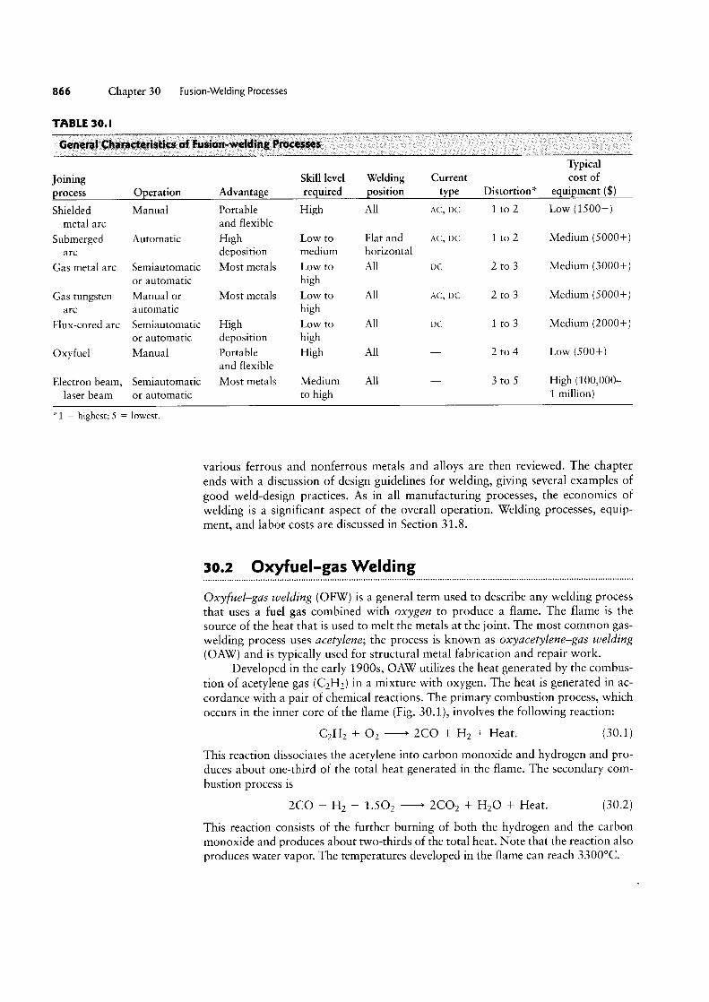
FIGURE 30.I Three basic types of oxyacetylene flames used in oxyfuel-gas welding andcutting operations: (a) neutral flame; (b) oxidizing flame; (c) carburizing, or reducing, flame.The gas mixture in (a) is basically equal volumes of oxygen and acetylene. (d) The principle ofthe oxyfuel-gas welding process.
Flame Types. The proportion of acetylene and oxygen in the gas mixture is animportant factor in oxyfuel-gas welding. At a ratio of 1:1 (i.e., when there is noexcess oxygen), the flame is considered to be neutral (Fig. 30.1a). With a greateroxygen supply, the flame can be harmful (especially for steels), because it oxidizesthe metal. For this reason, a flame with excess oxygen is known as an oxidizingflame (Fig. 3O.1b). Only in the welding of copper and copper-based alloys is anoxidizing flame desirable, because in those cases, a thin protective layer of slag(compounds of oxides) forms over the molten metal. If the oxygen is insufficientfor full combustion, the flame is known as a reducing, or carburizing, flame (a flamehaving excess acetylene; Fig. 30.1c). The temperature of a reducing flame is lower;hence, such a flame is suitable for applications requiring low heat, such as brazing,soldering, and flame-hardening operations.
Other fuel gases (such as hydrogen and methylacetylene propadiene) also canbe used in oxyfuel-gas welding. However, the temperatures developed by these gasesare lower than those produced by acetylene. Hence, they are used for welding(a) metals with low melting points (such as lead) and (b) parts that are thin andsmall. The flame with pure hydrogen gas is colorless; therefore, it is difficult toadjust the flame by eyesight.
Filler Metals. Filler metals are used to supply additional metal to the weld zoneduring welding. They are available as filler rods or wire (Fig. 3O.1d) and may bebare or coated with flux. The purpose of the flux is to retard oxidation of the sur-faces of the parts being welded by generating a gaseous shield around the weld zone.The flux also helps to dissolve and remove oxides and other substances from theweld zone, thus contributing to the formation of a stronger joint. The slag devel-oped (compounds of oxides, fluxes, and electrode-coating materials) protects themolten puddle of metal against oxidation as it cools.

8 8 Chapter 30 Fusion-Welding Processes
Welding Practice and Equipment. Oxyfuel-gas welding can be used with mostferrous and nonferrous metals for almost any workpiece thickness, but the relativelylow heat input limits the process to thicknesses of less than 6 mm _
Small joints made by this process may consist of a single-weld bead. Deep-Vgroove joints are made in multiple passes. Cleaning the surface of each weld beadprior to depositing a second layer is important for joint strength and in avoidingdefects (see Section 30.9). Wire brushes (hand or power) may be used for thispurpose.
The equipment for oxyfuel-gas welding consists basically of a welding torchconnected by hoses to high-pressure gas cylinders and equipped with pressure gages
and regulators (Fig. 302). The use of safety equipment (such as goggles with shadedlenses, face shields, gloves, and protective clothing) is essential. Proper connection ofthe hoses to the cylinders is an important factor in safety. Oxygen and acetylenecylinders have different threads, so the hoses cannot be connected to the wrongcylinders. The low equipment cost is an attractive feature of oxyfuel-gas welding.Although it can be mechanized, this operation is essentially manual and, hence,
Valves Mixer Tip
........ ...... I£3 i1¢'1§'§'if1z ~~¢1=ff;
Enlarged view 1
(H)
Oxygen :§ i Mixing chamber HN ,i~ .n _.¢v._ W1 wi nn V T* ,, f J‘v‘¢fy¢v%-%-‘~‘v5v‘vfv5~‘v‘ ,T T
Torch head “ ` it, Oxygen Union nut Mixer Tip
(D)
Gas regulators as V Hoses
Gas control valvesVan: "7 _ Welding torch
Oxygen cylinder / Welding tip
Combustible- gas cylinder ` Flame
(C)
FIGURE 30.2 (a) General view of, and (b) cross section of, a torch used in oxyacetylene
welding. The acetylene valve is opened first. The gas is lit with a spark lighter or a pilot light.Then the oxygen valve is opened and the flame adjusted. (c) Basic equipment used in
oxyfuel-gas welding. To ensure correct connections, all threads on acetylene fittings are left
handed, whereas those for oxygen are right handed. Oxygen regulators usually are paintedgreen and acetylene regulators red.

Section 30.3 Arc-welding Processes: Nonconsumable Electrode
C2H2 + O2 mixture
Torch
Flame heating = Of surfaces
if Clam 'si p ’=<ff2@1' 4.¥t..~ ; g»»=g;k§=,,em:;
(H) (D)
FIGURE 30.3 Schematic illustration of the pressure-gas welding process: (a) before and(b) after. Note the formation of a flash at the joint; later the flash can be trimmed off.
slow. However, it has the advantages of being portable, versatile, and economicalfor simple and low-quantity work.
Pressure-gas Welding. In this method, the welding of two components starts withthe heating of the interface by means of a torch using (typically) an oxyacetylene-gasmixture (Fig. 30.3a). After the interface begins to melt, the torch is withdrawn. A
force is applied to press the two components together (Fig. 30.3b) and is maintaineduntil the interface solidifies. Note the formation of a flash due to the upsetting of the
joined ends of the two components.
30.3 Arc-welding Processes: Nonconsumable Electrode
In arc welding, developed in the mid-18005, the heat required is obtained fromelectrical energy. The process involves either a consumable or a nonconsumableelectrode. An AC or a DC power supply produces an arc between the tip of the elec-
trode and the workpiece to be welded. The arc generates temperatures of about30,000°C, which are much higher than those developed in oxyfuel-gas welding.
In nonconsurnable-electrode welding processes, the electrode is typically a
tungsten electrode (Fig. 30.4). Because of the high temperatures involved, an exter-
nally supplied shielding gas is necessary to prevent oxidation of the weld zone.Typically, direct current is used, and its polarity (the direction of current flow) is im-
portant. The selection of current levels depends on such factors as the type of elec-
trode, metals to be welded, and depth and width of the weld zone.In straight polarity-also known as direct-current electrode negative (DCEN)-
the workpiece is positive (anode), and the electrode is negative (cathode). DCEN gen-
erally produces welds that are narrow and deep (Fig. 30.5a). In reverse polarity-alsoknown as direct-current electrode positive (DCEP)-the workpiece is negative and the
electrode is positive. Weld penetration is less, and the weld zone is shallower andwider (Fig. 30.5 b). Hence, DCEP is preferred for sheet metals and for joints with verywide gaps. ln the AC current method, the arc pulsates rapidly. This method is suitablefor welding thick sections and for using large-diameter electrodes at maximumcurrents (Fig. 30.5c).
Torchwithdrawn
Upsettingforce

870 Chapter 30 Fusion-Weldin g Processes
Foot pedal (optional)
DC (+)
(H)
DC (-)
(D)
AC
(C)
FIGURE 30.5 The effect ofpolarity and current type onweld beads: (a) DC currentwith straight polarity; (b) DC
current with reverse polarity;(c) AC current.
Travelif If 5
Electrical conductor
Tungsten electrodeGas passage
f lV if; Shielding gas
Filler wire \ §¥&` Arcrn.. “` ._~» Sldfd ld tl
Molten weld metal _ “'°'°‘ “""'“' 0| He We mea
(H)
inert-gas AC or DC
su pp V WeiderCooling-watersup
Torch
Filler rod
Workpiece
(bl
FIGURE 30.4 (a) The gas tungsten-arc welding process, formerly known as TIG (fortungsten-inert-gas) welding. (b) Equipment for gas tungsten-arc welding operations.
Heat Transfer in Arc Welding. The heat input in arc Welding is given by the equation
H VI- = e-, (30.3)I 1/
Where H is the heat input (] or BTU), I is the Weld length, V is the voltage applied, I is
the current (amperes), and 1/ is the welding speed. The term e is the efficiency of theprocess and varies from around 75% for shielded metal-arc welding to 90% for gasmetal-arc welding and submerged-arc Welding. The efficiency is an indication that notall of the available energy is beneficially used to melt material, because the heat is
conducted through the workpiece, some is lost by radiation, and still more is lost byconvection to the surrounding environment.
The heat input given by Eq. (30.3) melts a certain volume of material, usuallythe electrode or filler metal, and can also be expressed as
H = uV,,, = uAI, (30.4)
where u is the specific energy required for melting, V," is the volume of materialmelted, and A is the cross section of the Weld. Some typical values of u are given inTable 30.2. Equations (30.3) and (30.4) allow an expression of the welding speed:
VI1/ = eg. (30.5)
Although these equations have been developed for arc Welding, similar ones can beobtained for other fusion-welding operations as Well, taking into account differencesin Weld geometry and process efficiency.

Section 30.3 Arc-welding Processes: Nonconsumable Electrode
TABLE 30.2
Approximate Specific Energies Required to Melt aUnit Volume uf Commonly Welded Metals
Specific energy, uMaterial ]/mm3
Aluminum and its alloys 2.9Cast irons 7.8Copper 6.1Bronze (90Cu-10511) 4.2Magnesium 2.9Nickel 9.8Steels 9.1-10.3Stainless steels 9.3-9.6Titanium 14.3
EXAMPLE 30.l Welding Speed for Different Materials
Consider a situation in which a welding operation is Therefore, from Eq. (30.5)being performed with V == 20 volts, I = 200 A, andthe cross-sectional area of the weld bead is 30 mrnz. _ _Yi __ 0 75 (20l(200l 34 5 mfEstimate the welding speed if the workpiece and elec- V T e uA T l ' ) (2.9)(30) m S
trode are made of (a) aluminum, (b) carbon steel, and(c) titanium. Use an efficiency of 75%. Similarly, for carbon steel, u is estimated as
9.7 ]/mm3 (average of extreme values in the table)Snlution For aluminum, we note from Table 30.2 leading to 1/ = 10.3 mm/s For titanium u 14 3that the specific energy required is u = 2.9 ]/mm3. ]/mrn3, so that 1/ = 7.0 mm/s
Gas Tungsten-arc Welding. In gas tungsten-are welding (GTAW), formerlyknown as TIG (for “tungsten inert gas”) welding, the filler metal is supplied froma filler wire (Fig. 30.4a). Because the tungsten electrode is not consumed in thisoperation, a constant and stable arc gap is maintained at a constant current level.The filler metals are similar to the metals to be welded, and flux is not used. Theshielding gas is usually argon or helium (or a mixture of the two). Welding withGTAW may be done without filler metals-for example, in the welding of close-fitjoints.
Depending on the metals to be welded, the power supply is either DC at 200 A orAC at 5 00 A (Fig. 30.4b). In general, AC is preferred for aluminum and magnesium, be-cause the cleaning action of AC removes oxides and improves weld quality. Thorium orzirconium may be used in the tungsten electrodes to improve their electron emissioncharacteristics. The power supply ranges from 8 to 20 kW Contamination of the tung-sten electrode by the molten metal can be a significant problem, particularly in criticalapplications, because it can cause discontinuities in the weld. Therefore, contact of theelectrode with the molten-metal pool should be avoided.
The GTAW process is used for a wide variety of applications and metals, par-ticularly aluminum, magnesium, titanium, and the refractory metals. It is especiallysuitable for thin metals. The cost of the inert gas makes this process more expensivethan SMAW but provides welds of very high quality and surface finish. GTAW is

2 Chapter 30 Fuslon-Welding Processes
used in a variety of critical applications with a wide range of workpiece thicknessesand shapes. The equipment is portable.
Plasma-arc Welding. In plasma-arc welding (PAW), developed in the 1960s, a
concentrated plasma arc is produced and directed towards the weld area. The arc is
stable and reaches temperatures as high as 33,000°C. A plasma is an ionized hot gas
composed of nearly equal numbers of electrons and ions. The plasma is initiated be-
tween the tungsten electrode and the orifice by a low-current pilot arc. What makes
plasma-arc welding unlike other processes is that the plasma arc is concentrated be-
cause it is forced through a relatively small orifice. Operating currents usually are
below 100 A, but they can be higher for special applications. When a filler metal is
used, it is fed into the arc, as is done in GTAW. Arc and weld-zone shielding is sup-
plied by means of an outer-shielding ring and the use of gases such as argon, helium,
or mixtures.There are two methods of plasma-arc welding:
° In the transferred-arc method (Fig. 30.6a), the workpiece being welded is partof the electrical circuit. The arc transfers from the electrode to the workpiece-hence the term transferred.
° In the nontransferred method (Fig. 30.6b), the arc occurs between the elec-
trode and the nozzle, and the heat is carried to the workpiece by the plasma
gas. This thermal-transfer mechanism is similar to that for an oxyfuel flame
(see Section 30.2).
Compared with other arc-welding processes, plasma-arc welding has better
arc stability, less thermal distortion, and higher energy concentration, thus permit-
ting deeper and narrower welds. In addition, higher welding speeds, from 120 to
1000 mm/min, can be achieved. A variety of metals can be welded with part thick-
nesses generally less than 6 mm.The high heat concentration can penetrate completely through the joint
(known as the keyhole technique), with thicknesses as much as 20 mm for some ti-
tanium and aluminum alloys. In the keyhole technique, the force of the plasma arc
displaces the molten metal and produces a hole at the leading edge of the weld pool.
Plasma-arc welding (rather than the GTAW process) often is used for butt and lap
joints because of its higher energy concentration, better arc stability, and higher
welding speeds. Proper training and skill are essential for operators who use this
Tungstenelectrode
9 ig Plasma gas 1°
........ Shielding gas gg
,. l=¢wa
.;::v=‘I!§ V. :fel I (3) (U)
FIGURE 30.6 Two types of plasma-arc welding processes: (a) transferred and (b) nontrans-
ferred. Deep and narrow welds can be made by these processes at high welding speeds.

Section 30.4 Arc-welding Processes:
equipment. Safety considerations include protection against glare, spatter, and noisefrom the plasma arc.
Atomic-hydrogen Welding. In atomic-hydrogen welding (AHW), an arc is gener-ated between two tungsten electrodes in a shielding atmosphere of hydrogen gas. Thearc is maintained independently of the workpiece or parts being welded. The hydro-gen gas normally is diatomic (HZ), but where the temperatures are over 6,000°C nearthe arc, the hydrogen breaks down into its atomic form, simultaneously absorbing alarge amount of heat from the arc. When the hydrogen strikes the cold surface of theworkpieces to be joined, it recombines into its diatomic form and rapidly releases thestored heat. The energy in AHW can be varied easily by changing the distance be-tween the arc stream and the workpiece surface. This process is being replaced byshielded metal-arc welding, mainly because of the availability of inexpensive inertgases.
30.4 Arc-welding Processes: Consumable Electrode
There are several consumable-electrode arc-welding processes.
30.4.l Shielded Metal-arc WeldingShielded metal-arc welding (SMAW) is one of the oldest, simplest, and most versatilejoining processes. About 5 0% of all industrial and maintenance welding currently isperformed by this process. The electric arc is generated by touching the tip of acoated electrode against the workpiece and withdrawing it quickly to a distance suf-ficient to maintain the arc (Fig. 30.7a). The electrodes are in the shapes of thin, longrods (hence, this process also is known as stick welding) that are held manually.
The heat generated melts a portion of the electrode tip, its coating, and thebase metal in the immediate arc area. The molten metal consists of a mixture of thebase metal (the workpiece), the electrode metal, and substances from the coating onthe electrode; this mixture forms the weld when it solidifies. The electrode coatingdeoxidizes the weld area and provides a shielding gas to protect it from oxygen inthe environment.
A bare section at the end of the electrode is clamped to one terminal of thepower source, while the other terminal is connected to the workpiece being welded(Fig. 30.7b). The current, which may be DC or AC, usually ranges from 50 to 300 A.
Welding machine AC or DC
Consumable Electrode
power source and controls Solidified S189
Work AVC Elect d pg cable |q0|der;D e x \\\ lp; /l / Coating- E|e<;trode y, /. Electrode iff / /
V S workpiece iiii‘ \ er .. Sgéeldmg12; ._ .. ~1~11if1f LElectrode
Cable Weld metal Arc
FIGURE 30.7 Schematic illustration of the shielded metal-arc welding process. About 50%of all large-scale industrial-welding operations use this process.
874 Chapter 30 Fusion-Welding Processes
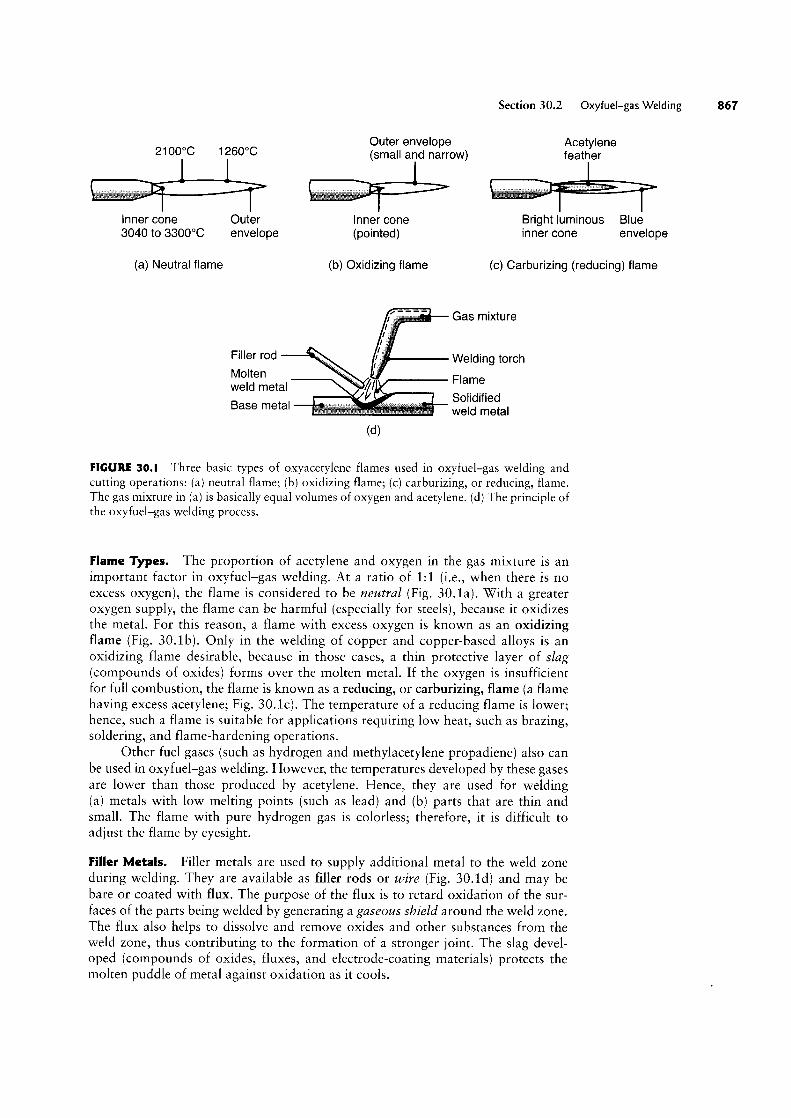
FIGURE 30.8 A deep weldshowing the buildup sequenceof eight individual weld beads.
For sheet-metal welding, DC is preferred because of the steady arc it produces. Powerrequirements generally are less than 10 kW.
The SMAW process has the advantages of being relatively simple, versatile,and requiring a smaller variety of electrodes. The equipment consists of a power
supply, cables, and an electrode holder. The SMAW process commonly is used in
general construction, shipbuilding, pipelines, and maintenance work. It is especially
useful for work in remote areas where a portable fuel-powered generator can be
used as the power supply. SMAW is best suited for workpiece thicknesses of 3 to19 mm, although this range can be extended easily by skilled operators using multi-ple-pass techniques (Fig. 30.8).The multiple-pass approach requires that the slag be removed after each weldbead. Unless removed completely, the solidified slag can cause severe corrosion ofthe weld area and lead to failure of the weld, but it also prevents the fusion of weldlayers and, therefore, compromises the weld strength. Before another weld is
applied, the slag should be removed completely-for example, by wire brushing orweld chipping. Consequently, both labor costs and material costs are high.
30.4.2 Submerged-arc Welding
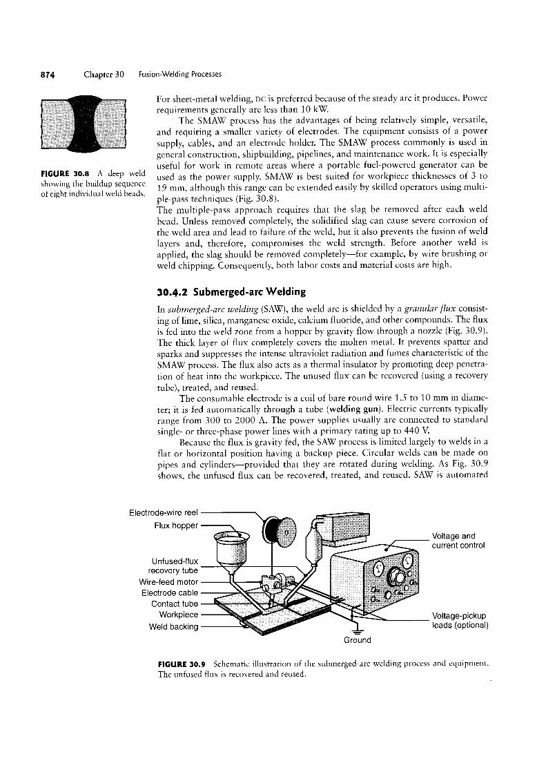
In submerged-arc welding (SAW), the weld arc is shielded by a granular flux consist-ing of lime, silica, manganese oxide, calcium fluoride, and other compounds. The flux
is fed into the weld zone from a hopper by gravity flow through a nozzle (Fig. 30.9).The thick layer of flux completely covers the molten metal. It prevents spatter andsparks and suppresses the intense ultraviolet radiation and fumes characteristic of the
SMAW process. The flux also acts as a thermal insulator by promoting deep penetra-tion of heat into the workpiece. The unused flux can be recovered (using a recoverytube), treated, and reused.
The consumable electrode is a coil of bare round wire 1.5 to 10 mm in diame-ter; it is fed automatically through a tube (welding gun). Electric currents typicallyrange from 300 to 2000 A. The power supplies usually are connected to standardsingle- or three-phase power lines with a primary rating up to 440 V
Because the flux is gravity fed, the SAW process is limited largely to welds in a
flat or horizontal position having a backup piece. Circular welds can be made onpipes and cylinders-provided that they are rotated during welding. As Fig. 30.9shows, the unfused flux can be recovered, treated, and reused. SAW is automated
Electrode-wire reel ____.,T Voltage and i current control
Ul1fUSeCl-f|UX 2 recovery tube _ yl..
Wire-feed motor Electrode cable
Wolkplece ipgp s/V ` Voltage-pickupWeld backing leads (optional)
Grciind
FIGURE 30.9 Schematic illustration of the submerged-arc welding process and equipment.The unfused flux is recovered and reused.
Section 30.4 Arc-welding Processes: Consumable Electrode 8
and is used to weld a variety of carbon and alloy steel and stainless-steel sheets orplates at speeds as high as 5 m/min. The quality of the Weld is very high-With goodtoughness, ductility, and uniformity of properties. The SAW process provides veryhigh welding productivity, depositing 4 to 10 times the amount of Weld metal perhour as the SMAW process. Typical applications include thick-plate Welding for ship-building and for pressure vessels.
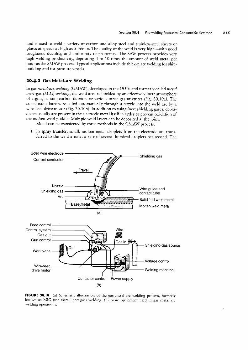
30.4.3 Gas Metal-arc WeldingIn gas metal-arc welding (GMAW), developed in the 19505 and formerly called metalinert-gas (MIG) welding, the Weld area is shielded by an effectively inert atmosphereof argon, helium, carbon dioxide, or various other gas mixtures (Fig. 30.10a). Theconsumable bare Wire is fed automatically through a nozzle into the Weld arc by aWire-feed drive motor (Fig. 30.10b). In addition to using inert shielding gases, deoxi-dizers usually are present in the electrode metal itself in order to prevent oxidation ofthe molten-weld puddle. Multiple-weld layers can be deposited at the joint.
Metal can be transferred by three methods in the GMAW process:
l. In spray transfer, small, molten metal droplets from the electrode are trans-ferred to the Weld area at a rate of several hundred droplets per second. The
Solid wire electrode 4 I Shieming gas
Current conductor wif:
Travel Nozzle
Wire guide andShielding gas i contact tube
Arc g; solidified weld meiai
i. Molten weld metal
fl=’
= 5rr ,.
5 Iin ,lf
“~I\ pryr N
(H)
Feed controlControl system A Wife
Gas our Gun control Gas in § Gun Shielding-gas sourceWorkpiece I'
ii ,..,__ ,I ..‘N E U Voltage control
Wire-feed 1-:: drive motor f ‘~»iir1i»lr Welding machine
Contactor control Power supply
(bl
FIGURE 30.I0 (a) Schematic illustration of the gas metal-arc Welding process, formerlyknown as MIG (for metal inert-gas) Welding. (b) Basic equipment used in gas metal-arcWelding operations.
876 Chapter 30 Fusion-Welding Processes
Arc shield composed of
vaporized and slag-formingcompounds protects metaltransfer through arc
Solidified slag
Molten slag
Solidified weld metal
transfer is spatter free and very stable. High DC currents and voltages andlarge-diameter electrodes are used with argon or an argon-rich gas mixture as
the shielding gas. The average current required in this process can be reduced
with the use of a pulsed arc, which superimposes high-amplitude pulses onto a
low, steady current. The process can be used in all welding positions.
In globular transfer, carbon-dioxide-rich gases are utilized, and globules are
propelled by the forces of the electric-arc transfer of the metal, resulting in
considerable spatter. High Welding currents are used, making it possible forgreater Weld penetration and higher welding speed than are achieved in spraytransfer. Heavier sections commonly are joined by this method.
2.
In short circuiting, the metal is transferred in individual droplets (more than50 per second) as the electrode tip touches the molten Weld metal and short-circuits. Low currents and voltages are utilized with carbon-dioxide-rich gases
and electrodes made of small-diameter Wire. The power required is about 2 kW
3.
The temperatures generated in GMAW are relatively low; consequently, this
method is suitable only for thin sheets and sections of less than 6 mm; otherwise in-
complete fusion may occur. The operation, which is easy to perform, is commonly
used for welding ferrous metals in thin sections. Pulsed-arc systems are used for thinferrous and nonferrous metals.
The GMAW process is suitable for Welding most ferrous and nonferrous metals
and is used extensively in the metal-fabrication industry. Because of the relativelysimple nature of the process, the training of operators is easy. The process is versatile,rapid, and economical, and Welding productivity is double that of the SMAW
process. The GMAW process can be automated easily and lends itself readily to
robotics and to flexible manufacturing systems (see Chapters 37 and 39).
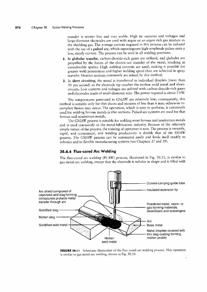
30.4.4 Flux-cored Arc Welding
The flux-cored arc welding (FCAW) process, illustrated in Fig. 30.11, is similar togas metal-arc Welding, except that the electrode is tubular in shape and is filled with
Current-carrying guide tube
insulated extension tip
YE?-,_
Powdered metal, vapor- orgas-forming materials,deoxidizers and scavengers$ArcBase metal
Metal droplets covered withthin slag coating forming
Molten molten puddleweld metal
FIGURE 30.1 I Schematic illustration of the flux-cored arc-welding process. This operationis similar to gas metal-arc welding, shown in Fig. 30.10.
Section 30.4 Arc-welding Processes:
flux (hence the term flux-cored). Cored electrodes produce a more stable arc, im-prove weld contour, and produce better mechanical properties of the weld metal. Theflux in these electrodes is much more flexible than the brittle coating used on SMAWelectrodes, so the tubular electrode can be provided in long coiled lengths.
The electrodes are usually 0.5 to 4 mm in diameter, and the power required is
about 20 kW. Self~shielded cored electrodes also are available. They do not requireany external shielding gas, because they contain emissive fluxes that shield the weldarea against the surrounding atmosphere. Small-diameter electrodes have made thewelding of thinner materials not only possible, but often preferable. Also, small-di-ameter electrodes make it relatively easy to weld parts in different positions, and theflux chemistry permits the welding of many metals.
The FCAW process combines the versatility of SMAW with the continuous andautomatic electrode-feeding feature of GMAW The process is economical and versa-tile, so it is used for welding a variety of joints, mainly on steels, stainless steels, andnickel alloys. The higher weld-metal deposition rate of the FCAW process (comparedwith that of GMAW) has led to its use in the joining of sections of all thicknesses. Theuse of tubular electrodes with very small diameters has extended the use of thisprocess to workpieces of smaller section size.
A major advantage of FCAW is the ease with which specific weld-metalchemistries can be developed. By adding alloying elements to the flux core, virtuallyany alloy composition can be produced. The process is easy to automate and is read-ily adaptable to flexible manufacturing systems and robotics.
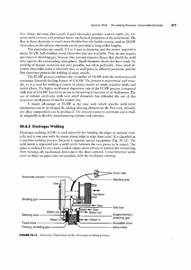
30.4.5 Electrogas Welding
Electrogas welding (EGW) is used primarily for welding the edges of sections verti-cally and in one pass with the pieces placed edge to edge (butt joint). It is classified asa machine-welding process, because it requires special equipment (Fig. 3012). Theweld metal is deposited into a weld cavity between the two pieces to be joined. Thespace is enclosed by two water-cooled copper dams (shoes) to prevent the molten slagfrom running off; mechanical drives move the shoes upward. Circumferential welds(such as those on pipes) also are possible, with the workpiece rotating.
Drive rollsElectrode conduit
Welding wireGas
4->Oscillator
Welding gun
gas- Gas boxGas
Water out -> Water outWelding wire 3#P=?g€m€maVY
Water in Water in S le mg gasFixed shoe Moveable shoe
Weld metalil'Primary shielding gas
FIGURE 30.l2 Schematic illustration of the electrogas-welding process.
Consumable Electrode 877

Chapter 30 Fusion-Welding Processes
Single or multiple electrodes are fed through a conduit, and a continuous arc is
maintained by flux-cored electrodes at up to 750 A or solid electrodes at 400 A.
Power requirements are about 20 kW Shielding is done by means of an inert gas,
such as carbon dioxide, argon, or helium-depending on the type of material being
Welded. The gas may be provided either from an external source, from a flux-cored
electrode, or from both.The equipment for electrogas Welding is reliable and training for operators is
relatively simple. Weld thickness ranges from 12 to 75 mm on steels, titanium, andaluminum alloys. Typical applications are in the construction of bridges, pressurevessels, thick-Walled and large-diameter pipes, storage tanks, and ships.
30.4.6 Electroslag Welding
Electroslag welding (ESW) and its applications are similar to electrogas welding(Fig. 30.13). The main difference is that the arc is started between the electrode tipand the bottom of the part to be vvelded. Flux is added, which then melts by the heatof the arc. After the molten slag reaches the tip of the electrode, the arc is extin-
guished. Heat is produced continuously by the electrical resistance of the moltenslag. Because the arc is extinguished, ESW is not strictly an arc-welding process.Single or multiple solid as Well as flux-cored electrodes may be used. The guide may
be nonconsumable (conventional method) or consumable.Electroslag Welding is capable of Welding plates with thicknesses ranging from
50 mm to more than 900 mm, and Welding is done in one pass. The current required is
about 600 A at 40 to 50 \L although higher currents are used for thick plates. The trav-
el speed of the weld is in the range from 12 to 36 mm/min. Weld quality is good. Thisprocess is used for large structural-steel sections, such as heavy machinery, bridges, oil
rigs, ships, and nuclear-reactor vessels.
Power source Control panel
r §3i "' S agar? ~ Electrode lead
X.; *Oscillation (optional)
Consumable guide tube work 5* Workpiece (QVOUHG) lead , if 4- Water in \Water out
FIGURE 30.|3 Equipment used for electroslag-Welding operations.
Wire reel
Wire-feed drive
Molten slag
Molten weld pool
Retaining shoe

Section 30.5 Electrodes for Arc Weld|ng 87
30.5 Electrodes for Arc Welding
Electrodes for consumable arc-welding processes are classified according to thefollowing properties:
° Strength of the deposited weld metal° Current (Ac or Dc)° Type of coating.
Electrodes are identified by numbers and letters (Table 30.3)-or by colorcode if the numbers and letters are too small to imprint. Typical coated-electrodedimensions are in the range from 150 to 460 mm in length and 1.5 to 8 mm indiameter.
Specifications for electrodes and filler metals (including dimensional toler-ances, quality control procedures, and processes) are published by the AmericanWelding Society (AWS) and the American National Standards Institute (ANSI).Some specifications appear in the Aerospace Materials Specifications (AMS) by theSociety of Automotive Engineers (SAE). Electrodes are sold by weight and are avail-able in a wide variety of sizes and specifications. Criteria for selection and recom-mendations for electrodes for a particular metal and its application can be found insupplier literature and in the various handbooks and references listed at the end ofthis chapter.
TABLE 30.3
Designations for Mild-steel Coated Electrodes
The prefix “E” designates arc welding electrode.The first two digits of four-digit numbers and the first three digits of five-digit numbersindicate minimum tensile strength:
E60XX 60,000 psiE70XX 70,000E110XX 110,000
The next-to-last digit indicates position:
EXX1X All positionsEXXZX Flat position and horizontal fillets
The last two digits together indicate the type of covering and the current to be used.The suffix (Example: EXXXX-A1) indicates the approximate alloy in the weld deposit:
-A1 0.5% Mo-B1 0.5% Cr, 0.5% Mo-B2 1.25% Cr, 0.5% Mo-B3 2.25% Cr, 1% M0-B4 2% Cr, 0.5% M0-B5 0.5% Cr, 1% Mo-C1 2.5% Ni-C2 3.25% Ni-C3 1% Ni, 0.35% Mo, 0.15% Cr-D1 and D2 0.25-0.45% Mo, 1.75% Mn-G 0.5% min. Ni, 0.3% min. Cr, 0.2% min. Mo,
0.1% min. \L 1% min. Mn (only one element required)
Note: Multiply pounds per square in. (psi) by 6.9 >< 10'3 to obtain megapascals (MPa).

8 0 Chapter 30 Fus|on-Welding Processes
Electrode Coatings. Electrodes are coated with claylike materials that include sili-
cate binders and powdered materials, such as oxides, carbonates, fluorides, metal al-
loys, cotton cellulose, and wood flour. The coating, which is brittle and takes part in
complex interactions during welding, has the following basic functions:
° Stabilize the arc.° Generate gases to act as a shield against the surrounding atmosphere; the gases
produced are carbon dioxide, water vapor, and small amounts of carbonmonoxide and hydrogen.
° Control the rate at which the electrode melts.° Act as a flux to protect the weld against the formation of oxides, nitrides, and
other inclusions and, with the resulting slag, to protect the molten-weld pool.° Add alloying elements to the weld zone to enhance the properties of the joint-
among these elements are deoxidizers to prevent the weld from becomingbrittle.
The deposited electrode coating or slag must be removed after each pass in
order to ensure a good weld; a wire brush (manual or power) can be used for this
purpose. Bare electrodes and wires made of stainless steels and aluminum alloys also
are available. They are used as filler metals in various welding operations.
30.6 Electron-beam Welding
In electron-beam welding (EBW), developed in the 1960s, heat is generated by high-
velocity narrow-beam electrons. The kinetic energy of the electrons is converted intoheat as they strike the workpiece. The process requires special equipment to focusthe beam on the workpiece, typically in a vacuum. The higher the vacuum, the morethe beam penetrates, and the greater is the depth-to-width ratio; thus, the methodsare called EBW-HV (for “high vacuum”) and EBW-MV (for “medium vacuum”);some materials also may also be welded by EBW-NV (for “no vacuum”).
Almost any metal can be welded by EBW, and workpiece thicknesses can rangefrom foil to plate. Capacities of electron guns range up to 100 kW The intenseenergy also is capable of producing holes in the workpiece (see keyhole technique,Section 30.3). Generally, no shielding gas, flux, or filler metal is required.
The EBW process has the capability of making high-quality welds that are
almost parallel sided, are deep and narrow, and have small heat-affected zones(see Section 30.9). Depth-to-width ratios range between 10 and 30. The sizes of
welds made by EBW are much smaller than those of welds made by conventional
processes. With the use of automation and servo controls, parameters can be con-
trolled accurately at welding speeds as high as 12 m/min.Almost any metal can be butt or lap welded with this process at thicknesses up
to 150 mm. Distortion and shrinkage in the weld area are minimal. The weldquality is good and of very high purity. Typical applications include the welding of
aircraft, missile, nuclear, and electronic components, as well as gears and shafts forthe automotive industry. Electron-beam welding equipment generates X-rays; hence,proper monitoring and periodic maintenance are essential.
30.7 Laser-beam Welding
Laser-beam welding (LBW) utilizes a high-power laser beam as the source of heat,to produce a fusion weld. Because the beam can be focused onto a very small area,
it has high energy density and deep-penetrating capabil-ity. The beam can be directed, shaped, and focused pre-cisely on the workpiece. Consequently, this process is
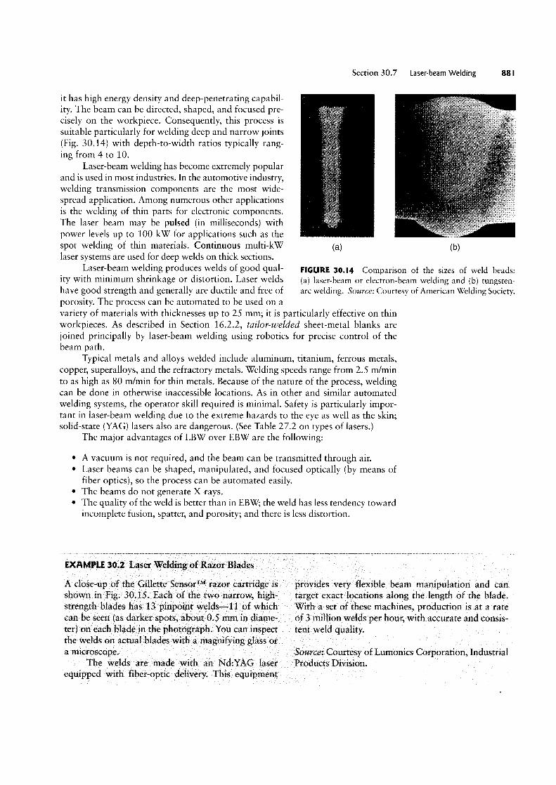
suitable particularly for welding deep and narrow joints(Fig. 30.14) with depth-to-width ratios typically rang-ing from 4 to 10.
Laser-beam welding has become extremely popularand is used in most industries. In the automotive industry,welding transmission components are the most wide-spread application. Among numerous other applicationsis the welding of thin parts for electronic components.The laser beam may be pulsed (in milliseconds) withpower levels up to 100 kW for applications such as thespot welding of thin materials. Continuous multi-kWlaser systems are used for deep welds on thick sections.
Laser-beam welding produces welds of good qual-ity with minimum shrinkage or distortion. Laser welds
Section 30.7 Laser-beam Welding 88|
(H) (D)
FIGURE 30.I4 Comparison of the sizes of weld beads:(a) laser-beam or electron-beam welding and (b) tungsten-arc welding. Source: Courtesy of American Welding Society.have good strength and generally are ductile and free of
porosity. The process can be automated to be used on avariety of materials with thicknesses up to 25 mm; it is particularly effective on thinworkpieces. As described in Section 16.2.2, tailor-welded sheet-metal blanks arejoined principally by laser-beam welding using robotics for precise control of thebeam path.
Typical metals and alloys welded include aluminum, titanium, ferrous metals,copper, superalloys, and the refractory metals. Welding speeds range from 2.5 m/minto as high as 80 m/min for thin metals. Because of the nature of the process, weldingcan be done in otherwise inaccessible locations. As in other and similar automatedwelding systems, the operator skill required is minimal. Safety is particularly impor-tant in laser-beam welding due to the extreme hazards to the eye as well as the skin;solid-state (YAG) lasers also are dangerous. (See Table 27.2 on types of lasers.)
The major advantages of LBW over EBW are the following:
° A vacuum is not required, and the beam can be transmitted through air.° Laser beams can be shaped, manipulated, and focused optically (by means of
fiber optics), so the process can be automated easily.° The beams do not generate X-rays.° The quality of the weld is better than in EBW; the weld has less tendency toward
incomplete fusion, spatter, and porosity; and there is less distortion.
EXAMPLE 30.2 Laser Welding of Razor Blades
A close-up of the Gillette Sensorm razor cartridge is
shown in Fig. 30.15. Each of the two narrow, high-strength blades has 13 pinpoint welds-11 of whichcan be seen (as darker spots, about 0.5 mm in diame-ter) on each blade in the photograph. You can inspectthe welds on actual blades with a magnifying glass ora microscope.
The welds are made with an Nd:YAG laserequipped with fiber-optic delivery. This equipment
provides very flexible beam manipulation and cantarget exact locations along the length of the blade.With a set of these machines, production is at a rateof 3 million welds per hour, with accurate and consis-tent weld quality.
Source: Courtesy of Lumonics Corporation, IndustrialProducts Division.

2 Chapter 30 Fusion-Welding Processes
FIGURE 30.15 Detail of Gillette Sensor”razor cartridge, showing laser spot welds.
30.8 Cutting
In addition to being cut by mechanical means, material can be cut into various con-tours with the use of a heat source that melts and removes a narrow zone in theworkpiece. The sources of heat can be torches, electric arcs, or lasers.
Oxyfuel-gas Cutting. Ox;/fuel-gas cutting (OFC) is similar to oxyfuel welding,but the heat source is now used to remove a narrow zone from a metal plate or sheet(Fig. 30.16a). This process is suitable particularly for steels. The basic reactions withsteel are
Fe + O l> FeO + Heat, (30.6)
3Fe -1- 202 -> Fe3O4 + Heat, (30.7)
and
4Fe + 302 -> 2 Fe2O3 + Heat. (30.8)
The greatest heat is generated by the second reaction, and it can produce a tem-
perature rise to about 870°C. However, this temperature is not sufficiently high tocut steels; therefore, the workpiece is preheated with fuel gas, and oxygen is intro-duced later (see the nozzle cross section in Fig. 30.16a). The higher the carbon con-tent of the steel, the higher is the preheating temperature required. Cutting takesplace mainly by the oxidation (burning) of the steel; some melting also takes place.Cast irons and steel castings also can be cut by this method. The process generates a
kerf similar to that produced by sawing with a saw blade or by wire electrical-discharge machining (see Fig. 2712).

Section 30 8 Cuttlng 883
fg
Torch
Oxygen Preheat flames (oxyacetylene) Torchl-
WorkpiecePlate Drag lines
Kerr _,| Thlcknessi
Slag (iron and /ll _>| (__rroh oxrde) Drag
_//(|_l»(
(3) (b)
FIGURE 30.l6 (a) Flame cutting of a steel plate with an oxyacetylene torch, and a crosssection of the torch nozzle. (b) Cross section of a flame-cut plate, showing drag lines.
The maximum thickness that can be cut by OFC depends mainly on the gasesused. With oxyacetylene gas, the maximum thickness is about 300 mm; with oxyhy-drogen, it is about 600 mm. Kerf widths range from about 1.5 to 10 mm, with rea-sonably good control of tolerances. The flame leaves drag lines on the cut surface(Fig. 30.l6b), resulting in a rougher surface than that produced by processes such assawing, blanking, or other operations that use mechanical cutting tools. Distortioncaused by uneven temperature distribution can be a problem in OFC.
Although long used for salvage and repair work, OFC can be used in manufac-turing as well. Torches may be guided along specified paths either manually, mechan-ically, or automatically by machines using programmable controllers and robots.Underwater cutting is done with specially designed torches that produce a blanket ofcompressed air between the flame and the surrounding water.
Arc Cutting. Arc-cutting processes are based on the same principles as arc-weldingprocesses. A variety of materials can be cut at high speeds by arc cutting. As in weld-ing, these processes also leave a heat-affected zone that needs to be taken into account,particularly in critical applications.
In air carbon-arc cutting (CAC-A), a carbon electrode is used and the moltenmetal is blown away by a high-velocity air jet; thus, the metal being cut doesn’t haveto oxidize. This process is used especially for gouging and scarfing (removal of metalfrom a surface). However, the process is noisy, and the molten metal can be blownsubstantial distances and cause safety hazards.
Plasma-arc cutting (PAC) produces the highest temperatures. It is used for therapid cutting of nonferrous and stainless-steel plates. The cutting productivity ofthis process is higher than that of oxyfuel-gas methods. PAC produces a good sur-face finish and narrow kerfs, and is the most popular cutting process utilizing pro-grammable controllers employed in manufacturing today.
Electron beams and lasers also are used for very accurately cutting a wide varietyof metals, as was described in Sections 27.6 and 27.7. The surface finish is better thanthat of other thermal cutting processes, and the kerf is narrower.

®Q
wh
GD'
so'U
Ph
ra"1
ua
C
71
C2.
o ?5E:
:lon
'o-\o
QN
U)
U1
(U|-/I
30.9 The Weld joint, Quality, and Testing
Three distinct zones can be identified in a typical weld joint, as shown in Fig. 30.171
I. Base metal
2. Heat-affected zone
3. Weld metal.
The metallurgy and properties of the second and third zones depend strongly on the
type of metals joined, the particular joining process, the filler metals used (if any),
and welding process variables. A joint produced without a filler metal is called
autogenous, and its weld zone is composed of the resolidified base metal. A jointmade with a filler metal has a central zone called the weld metal and is composed of
a mixture of the base and the filler metals.
Solidification of the Weld Metal. After the application of heat and the introduc-tion of the filler metal (if any) into the weld zone, the weld joint is allowed to cool toambient temperature. The solidijqcation process is similar to that in casting and be-
gins with the formation of columnar (dendritic) grains. (See Fig. 10.3.) These grainsare relatively long and form parallel to the heat flow. Because metals are much bet-
ter heat conductors than the surrounding air, the grains lie parallel to the plane of
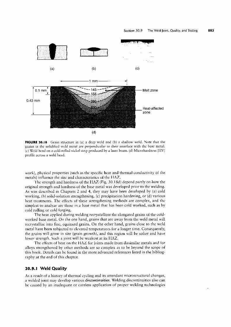
the two components being welded (Fig. 30.18a). In contrast, the grains in a shallowweld are shown in Figs. 30.18b and c.
Grain structure and grain size depend on the specific metal alloy, the particu-lar welding process employed, and the type of filler metal. Because it began in a
molten state, the weld metal basically has a cast structure, and since it has cooledslowly, it has coarse grains. Consequently, this structure generally has low strength,toughness, and ductility. However, the proper selection of filler-metal compositionor of heat treatments following welding can improve the mechanical properties of
the joint.The resulting structure depends on the particular alloy, its composition, and
the thermal cycling to which the joint is subjected. For example, cooling rates may be
controlled and reduced by pre/venting the general weld area prior to welding.
Original Fusion zone Heat-affectedstructure (weld metal) zone
faG o><C
13|gm
'Lulo
(QL.
c/:N
sn
2_0ma-
39.és1%
gs:QQQ
o*'h
N
FY
EE.
‘L*'h c
2.oF
2‘L
Q.
No
:sFD
Tmpeture
O2.
Q.IJ
Q
I___`|s
mga;§~"§Dcn§Q2
:"¢.(D.U:°Z6Eéaé=Sgg’
mage2EmQ3592Qw
3‘°3Q
§'22.2OEO'5;
9.23
Egfn
9.._.3
ESQ<1>‘°gi
temperatureof base metal
Preheating is important, particularly for metals hav-ing high thermal conductivity, such as aluminum andcopper. Without preheating, the heat produced duringwelding dissipates rapidly through the rest of the partsbeing joined.
Heat-affected Zone. The heat-affected zone (HAZ)is within the base metal itself. It has a microstructuredifferent from that of the base metal prior to welding,because it has been temporarily subjected to elevatedtemperatures during welding. The portions of thebase metal that are far enough away from the heatsource do not undergo any microstructural changesduring welding because of the far lower temperatureto which they are subjected.
The properties and microstructure of the HAZdepend on (a) the rate of heat input and cooling and(b) the temperature to which this zone was raised. In
addition to metallurgical factors (such as the originalgrain size, grain orientation, and degree of prior cold
Section 30.9 The Weldjoint Quality and Testmg 88
(H) (b) (C)
'< 1 mm >1
0.1 mm - Melt zone
0.43 mm
Heat-affectedzone
Z T (d)
FIGURE 30.18 Grain structure in (a) a deep weld and (b) a shallow weld. Note that thegrains in the solidified weld metal are perpendicular to their interface with the base metal.(c) Weld bead on a cold-rolled nickel strip produced by a laser beam. (d) Microhardness (HV)
profile across a weld bead.
work), physical properties (such as the specific heat and thermal conductivity of themetals) influence the size and characteristics of the HAZ.
The strength and hardness of the HAZ (Fig. 3O.18d) depend partly on how theoriginal strength and hardness of the base metal was developed prior to the welding.As was described in Chapters 2 and 4, they may have been developed by (a) coldworking, (b) solid-solution strengthening, (c) precipitation hardening, or (d) variousheat treatments. The effects of these strengthening methods are complex, and thesimplest to analyze are those in a base metal that has been cold worked, such as bycold rolling or cold forging.
The heat applied during welding recrystallizes the elongated grains of the cold-worked base metal. On the one hand, grains that are away from the weld metal willrecrystallize into fine, equiaxed grains. On the other hand, grains close to the weldmetal have been subjected to elevated temperatures for a longer time. Consequently,the grains will grow in size (grain growth), and this region will be softer and havelower strength. Such a joint will be weakest at its HAZ.
The effects of heat on the HAZ for joints made from dissimilar metals and foralloys strengthened by other methods are so complex as to be beyond the scope ofthis book. Details can be found in the more advanced references listed in the bibliog-raphy at the end of this chapter.
30.9.l Weld Quality
As a result of a history of thermal cycling and its attendant microstructural changes,a welded joint may develop various discontinuities. Welding discontinuities also canbe caused by an inadequate or careless application of proper welding technologies
886 Chapter 30 Fusion-Welding Processes
or by poor operator training. The major discontinuities that affect weld quality aredescribed here.
Porosity. Porosity in welds may be caused by
° Gases released during melting of the weld area, but trapped during solidification.° Chemical reactions during welding.° Contaminants.
Most welded joints contain some porosity, which is generally in the shape ofspheres or of elongated pockets. (See also Section 10.6.1.) The distribution of poros-ity in the weld zone may be random, or the porosity may be concentrated in a certainregion in the zone.
Porosity in welds can be reduced by the following practices:
° Proper selection of electrodes and filler metals.' Improved welding techniques, such as preheating the weld area or increasing
the rate of heat input.° Proper cleaning and the prevention of contaminants from entering the weld
zone.° Reduced welding speeds to allow time for gas to escape.
Slag lnclusions. Slug inclusions are compounds such as oxides, fluxes, and electrode-coating materials that are trapped in the weld zone. If shielding gases are not effectiveduring welding, contamination from the environment also may contribute to such in-
clusions. Welding conditions are important as well: With control of welding processparameters, the molten slag will float to the surface of the molten weld metal and thuswill not become entrapped.
Slag inclusions can be prevented by the following practices:
° Cleaning the weld-bead surface by means of a wire brush (hand or power) or achipper before the next layer is deposited.
° Providing sufficient shielding gas.° Redesigning the joint to permit sufficient space for proper manipulation of the
puddle of molten weld metal.
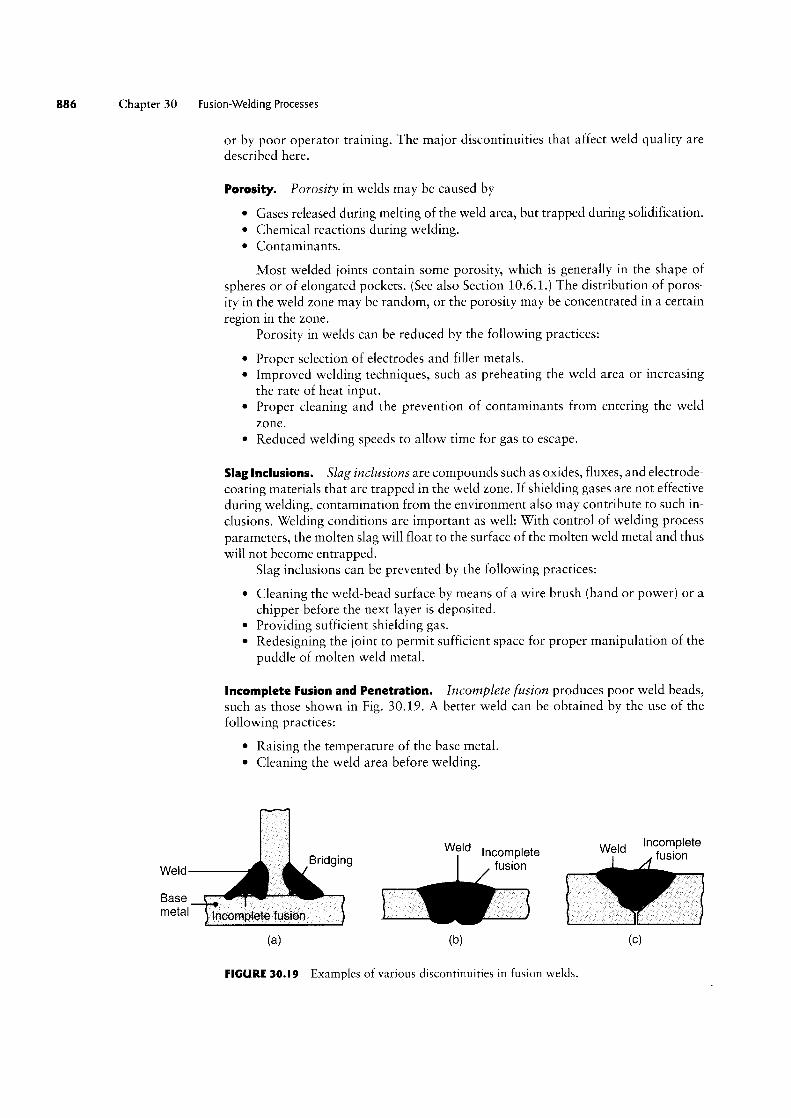
Incomplete Fusion and Penetration. Incomplete fusion produces poor weld beads,such as those shown in Fig. 30.19. A better weld can be obtained by the use of thefollowing practices:
° Raising the temperature of the base metal.° Cleaning the weld area before welding.
letWeld Incomplete Weld nigggn e
I /IWe|d fUSIOI'\Bndgmg
Base ` ` "
meta' Incomplete fusion
(3) (D) (C)
FIGURE 30.I9 Examples of various discontinuities in fusion welds.

Section 30.9 The Weld joint. Quality, and Testing
Underfilt Crack
Inclusions BHS9 meta'
Incompletepenetration
(8)
Good weldOverlap Undercut
PorosityLack ofpenetration
(D) (C)
FIGURE 30.20 Examples of various defects in fusion Welds.
' Modifying the joint design and changing the type of electrode used.° Providing sufficient shielding gas.
Incomplete penetration occurs when the depth of the welded joint is insufficient.Penetration can be improved by the following practices:
° Increasing the heat input.° Reducing the travel speed during the Welding.° Modifying the joint design.° Ensuring that the surfaces to be joined fit each other properly.
Weld Profile. Weld profile is important not only because of its effects on thestrength and appearance of the Weld, but also because it can indicate incompletefusion or the presence of slag inclusions in multiple-layer welds.
° Underfilling results When the joint is not filled with the proper amount of weldmetal (Fig. 30.20a).
° Undercutting results from the melting away of the base metal and the consequentgeneration of a groove in the shape of a sharp recess or notch (Fig. 3O.20b). If it
is deep or sharp, an undercut can act as a stress raiser and can reduce the fatiguestrength of the joint; in such cases, it may lead to premature failure.
° Overlap is a surface discontinuity (Fig. 30.20b) usually caused by poor Weld-ing practice or by the selection of improper materials. A good Weld is shown in
Fig. 3o.20¢_
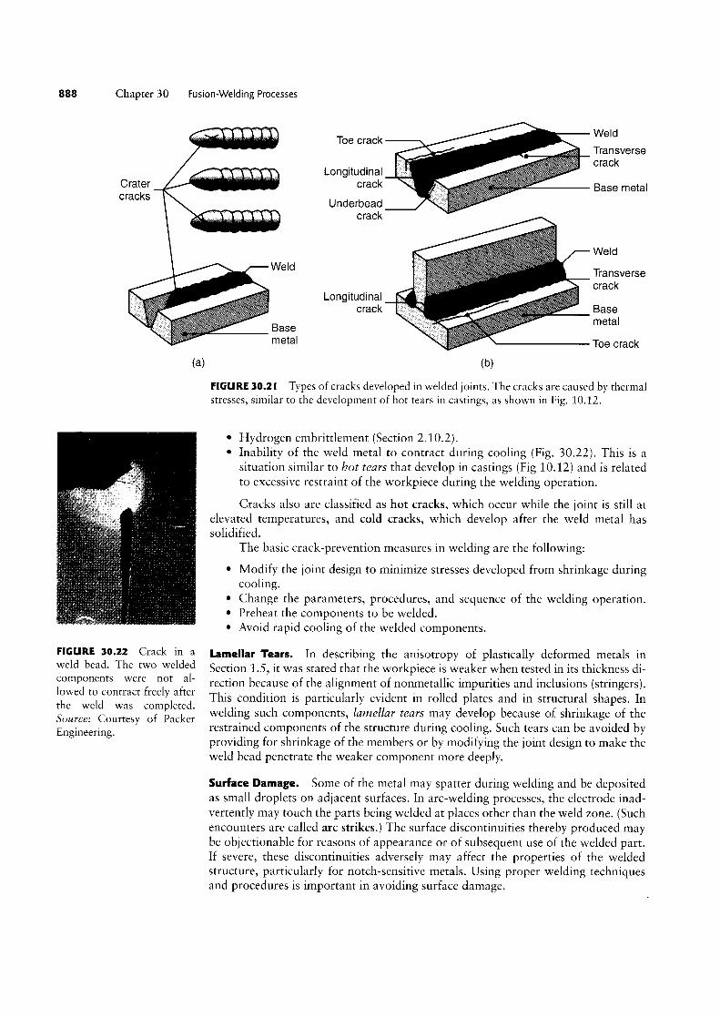
Cracks. Cracks may occur in various locations and directions in the Weld area.Typical types of cracks are longitudinal, transverse, crater, underbead, and toe cracks(Fig. 3021).
Cracks generally result from a combination of the follovving factors:
° Temperature gradients that cause thermal stresses in the Weld zone.° Variations in the composition of the Weld zone that cause different rates of
contraction during cooling.° Embrittlement of grain boundaries (Section 1.5.2), caused by the segregation
of such elements as sulfur to the grain boundaries and occurring when thesolid-liquid boundary moves when the Weld metal begins to solidify.
888 Chapter 30 Fusion-Welding Processes
W Id Toe Crack e¢, Transverse` Crack Longitudinal ssssf
Cracks Underbead "”" Cravk
Weld
Weld Transversecrack » >;§ Longitudinal Crack Base metal Base meta' l-Toe crack
(H)
FIGURE 30.21 Types of cracks developed in welded joints. The cracks are caused by thermalstresses, similar to the development of hot tears in castings, as shown in Fig. 10.12.
solidified.
cooling.
° Hydrogen embrittlement (Section 2.10.2).° Inability of the weld metal to contract during cooling (Fig. 3022). This is a
situation similar to hot tears that develop in castings (Fig 10.12) and is relatedto excessive restraint of the workpiece during the welding operation.
Cracks also are classified as hot cracks, which occur while the joint is still atelevated temperatures, and cold cracks, which develop after the weld metal has
The basic crack-prevention measures in welding are the following:
° Modify the joint design to minimize stresses developed from shrinkage during
° Change the parameters, procedures, and sequence of the welding operation.° Preheat the components to be welded.° Avoid rapid cooling of the welded components.
"GURE 3°-22 Crack in H Lamellar Tears. In describing the anisotropy of plastically deformed metals inWeld bead- The “Ve Welded Section 1.5, it was stated that the workpiece is weaker when tested in its thickness di~components were not al-lowed to contract freely afterthe weld was completed.Source: Courtesy of PackerEngineering.
rection because of the alignment of nonmetallic impurities and inclusions (stringers).This condition is particularly evident in rolled plates and in structural shapes. Inwelding such components, lamellar tears may develop because of shrinkage of therestrained components of the structure during cooling. Such tears can be avoided byproviding for shrinkage of the members or by modifying the joint design to make theweld bead penetrate the weaker component more deeply.
Surface Damage. Some of the metal may spatter during welding and be depositedas small droplets on adjacent surfaces. In arc-welding processes, the electrode inad-vertently may touch the parts being welded at places other than the weld zone. (Suchencounters are called arc strikes.) The surface discontinuities thereby produced maybe objectionable for reasons of appearance or of subsequent use of the welded part.If severe, these discontinuities adversely may affect the properties of the weldedstructure, particularly for notch-sensitive metals. Using proper welding techniquesand procedures is important in avoiding surface damage.
Section 30.9 The Weldjoint, Quality, and Testing 889
WeldWeld I
t 1 : - ; -Transverse shrinkage : E Weld Neutramxis Wejd
l
I j
Angular distortion Lgagmjgglal
(H) (D) (C) ld)
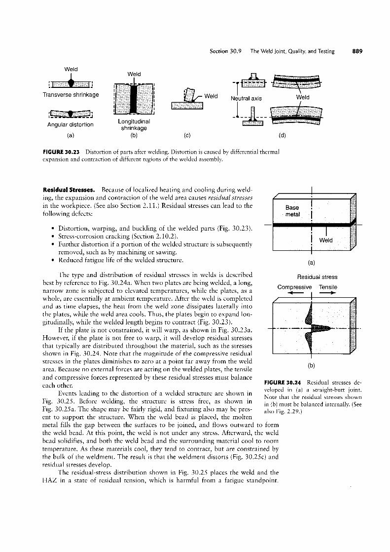
FIGURE 30.23 Distortion of parts after welding. Distortion is caused by differential thermalexpansion and contraction of different regions of the welded assembly.
Residual Stresses. Because of localized heating and cooling during weld-ing, the expansion and contraction of the weld area causes residual stressesin the workpiece. (See also Section 2.11.) Residual stresses can lead to thefollowing defects:
° Distortion, warping, and buckling of the welded parts (Fig. 30.23).° Stress-corrosion cracking (Section 2.10.2).° Further distortion if a portion of the welded structure is subsequently
removed, such as by machining or sawing.° Reduced fatigue life of the welded structure.
The type and distribution of residual stresses in welds is describedbest by reference to Fig. 30.24a. When two plates are being welded, a long,narrow zone is subjected to elevated temperatures, while the plates, as awhole, are essentially at ambient temperature. After the weld is completedand as time elapses, the heat from the weld zone dissipates laterally intothe plates, while the weld area cools. Thus, the plates begin to expand lon-gitudinally, while the welded length begins to contract (Fig. 30.23).
If the plate is not constrained, it will warp, as shown in Fig. 30.23a.However, if the plate is not free to warp, it will develop residual stressesthat typically are distributed throughout the material, such as the stressesshown in Fig. 30.24. Note that the magnitude of the compressive residualstresses in the plates diminishes to zero at a point far away from the weldarea. Because no external forces are acting on the welded plates, the tensileand compressive forces represented by these residual stresses must balanceeach other.
Events leading to the distortion of a welded structure are shown inFig. 30.25 _ Before welding, the structure is stress free, as shown inFig. 30.25 a. The shape may be fairly rigid, and fixturing also may be pres-ent to support the structure. When the weld bead is placed, the molten
Base . Ield
(H)
Residual stress
Compressive Tensile<-- (bl
FIGURE 30.24 Residual stresses de-veloped in (a) a straight-butt joint.Note that the residual stresses shownin (b) must be balanced internally. (Seealso Fig. 2.29.)
metal fills the gap between the surfaces to be joined, and flows outward to formthe weld bead. At this point, the weld is not under any stress. Afterward, the weldbead solidifies, and both the weld bead and the surrounding material cool to roomtemperature. As these materials cool, they tend to contract, but are constrained bythe bulk of the weldment. The result is that the weldment distorts (Fig. 30.25c) andresidual stresses develop.
The residual-stress distribution shown in Fig. 30.25 places the weld and theHAZ in a state of residual tension, which is harmful from a fatigue standpoint.

0 Chapter 30 Fusron-Welding Processes
Hot zoneRgid (expanded) No Snape C t t_
on rac |onframe Men change gg It (pushed Out) V V' ema { ssss (residual) 1-~. 1 sss s tensile , sss . ssss , . stress
i if T @ Distortion
(D) (C)
FIGURE 30.25 Distortion of a welded structure. Source: After ].A. Schey.
Many welded structures will use cold-worked materials (such as extruded or roll-formed shapes), and these are relatively strong and fatigue resistant. The weld itselfmay have porosity (see Fig. 3O.20b), which can act as a stress riser and aid fatigue-crack growth, or there could be other cracks that can grow in fatigue. In general, theHAZ is less fatigue resistant than the base metal. Thus, the residual stresses devel-oped can be very harmful, and it is not unusual to further treat welds in highlystressed or fatigue-susceptible applications.
In complex welded structures, residual-stress distributions are three dimensionaland, consequently, difficult to analyze. The previous discussion involved two platesthat were not restrained from movement. In other words, the plates were not an inte-gral part of a larger structure. If, however, they are restrained, reaction stresses will begenerated, because the plates are not free to expand or contract. This situation arisesparticularly in structures with high stiffness.
Stress Relieving of Welds. The problems caused by residual stresses (such as dis-tortion, buckling, and cracking) can be reduced by preheating the base metal or theparts to be welded. Preheating reduces distortion by reducing the cooling rate andthe level of thermal stresses developed (by lowering the elastic modulus). This tech-nique also reduces shrinkage and possible cracking of the joint.
For optimum results, preheating temperatures and cooling rates must be con-trolled carefully in order to maintain acceptable strength and toughness in the weldedstructure. The workpieces may be heated in several ways, including (a) in a furnace,(b) electrically (resistively or inductively), or (c) by radiant lamps or a hot-air blast forthin sections. The temperature and time required for stress relieving depend on thetype of material and on the magnitude of the residual stresses developed.
Other methods of stress relieving include peening, hammering, or surfacerolling of the weld-bead area. These techniques induce compressive residual stresses,which, in turn, lower or eliminate tensile residual stresses in the weld. For multilayerwelds, the first and last layers should not be peened, in order to protect them againstpossible peening damage.
Residual stresses can also be relieved or reduced by plastically deforming thestructure by a small amount. For instance, this technique can be used in weldedpressure vessels by pressurizing the vessels internally (proof stressing). In order to re-duce the possibility of sudden fracture under high internal pressure, the weld mustbe made properly and must be free of notches and discontinuities, which could actas points of stress concentration.
In addition to being preheated for stress relieving, welds may be heat treatedby various other techniques in order to modify other properties. These techniques

Section 30.9 The Weldjoint Quality and Testing
include the annealing, normalizing, quenching, and tempering of steels and the solu-tion treatment and aging of various alloys as described in Chapter 4.
30.9.2 Weldability
The u/eldability of a metal is usually defined as its capacity to be Welded into a spe-cific structure that has certain properties and characteristics and will satisfactorilymeet service requirements. Weldability involves a large number of variables; hence,generalizations are difficult. As noted previously, the material characteristics (suchas alloying elements, impurities, inclusions, grain structure, and processing history)of both the base metal and the filler metal are important. For example, the Weldabil-ity of steels decreases with increasing carbon content because of martensite forma-tion (vvhich is hard and brittle) and thus reduces the strength of the Weld. Coatedsteel sheets present various challenges in welding, depending on the type and thick-ness of the coating.
Because of the effects of melting and solidification and of the associated mi-crostructural changes, a thorough knowledge of the phase diagram and the responseof the metal or alloy to sustained elevated temperatures is essential. Also influencingWeldability are mechanical and physical properties: strength, toughness, ductility,notch sensitivity, elastic modulus, specific heat, melting point, thermal expansion,surface-tension characteristics of the molten metal, and corrosion resistance.
The preparation of surfaces for Welding is important, as are the nature andproperties of surface-oxide films and of adsorbed gases. The particular Weldingprocess employed significantly affects the temperatures developed and their distri-bution in the Weld zone. Other factors that affect Weldability are shielding gases,fluxes, moisture content of the coatings on electrodes, Welding speed, Welding posi-tion, cooling rate, and level of preheating, as Well as such postvvelding techniques asstress relieving and heat treating.
Weldability of Ferrous Materials:
° Plain-carbon steels: Weldability is excellent for lovv-carbon steels, fair to goodfor medium-carbon steels, poor for high-carbon steels.
° Lou/-alloy steels: Weldability is similar to that of medium-carbon steels.° High-alloy steels: \X/eldability generally is good under well-controlled conditions.° Stainless steels: These generally are weldable by various processes.° Cast irons: These generally are weldable, although their vveldability varies
greatly.
Weldability of Nonferrous Materials:
° Aluminum alloys: These are weldable at a high rate of heat input. An inertshielding gas and lack of moisture are important. Aluminum alloys containingzinc or copper generally are considered unvveldable.
° Copper alloys: Depending on composition, these generally are weldable at a highrate of heat input. An inert shielding gas and lack of moisture are important.
° Magnesium alloys: These are weldable With the use of a protective shieldinggas and fluxes.
° Nickel alloys: Weldability is similar to that of stainless steels. The lack of sul-fur is undesirable.
° Titanium alloys: These are weldable with the proper use of shielding gases.° Tantalum: Weldability is similar to that of titanium.

Chapter 30 Fusion-Welding Processes
' Tungsten: Weldable under well-controlled conditions.' Molybdenum: Weldability is similar to that of tungsten.° Niobium (colurnbiufn): Possesses good Weldability.
30.9.3 Testing of Welds
As in all manufacturing processes, the quality of a Welded joint is established by test-ing. Several standardized tests and test procedures have been established. They areavailable from many organizations, such as the American Society for Testing andMaterials (ASTM), the American Welding Society (AWS), the American Society ofMechanical Engineers (ASME), the American Society of Civil Engineers (ASCE),and various federal agencies.
Welded joints may be tested either destructiz/ely or nondestructn/ely. (See alsoSections 36.10 and 36.11.) Each technique has certain capabilities and limitations,as Well as sensitivity, reliability, and requirements for special equipment and opera-tor skill.
Destructive Testing Techniques:
° Tension test: Longitudinal and transverse tension tests are performed on speci-mens removed from actual welded joints and from the Weld-metal area.Stress-strain curves are then obtained by the procedures described in Section 2.2.These curves indicate the yield strength, Y, ultimate tensile strength, UTS, andductility of the Welded joint (elongation and reduction of area) in different loca-tions and directions.
° Tension-shear test: The specimens in the tension-shear test (Figs. 3O.26a and b)
are prepared to simulate conditions to which actual Welded joints are subjected.These specimens are subjected to tension so that the shear strength of the weldmetal and the location of fracture can be determined.
f Iij: i
nom bend \ § -Q
/Lo gitudinal tension shear W/ Romer Face bend
weld
`\ Ir!Transverse Side bend tension shear AT $7
(fi) (bi (C)
FIGURE 30.26 (a) Specimens for longitudinal tension-shear testing and for transfer tension-shear testing. (b) Wraparound bend-test method. (c) Three-point transverse bending of Weldedspecimens.
Section 30.10 joint Design and Process Selection
° Bend test: Several bend tests have been developed to determine the ductilityand strength of welded joints. In one common test, the welded specimen is
bent around a fixture (wraparound bend test, Fig. 30.26c). In another test, thespecimens are tested in three-point transverse bending (Fig. 30.26d; see alsoFig. 2.11a). These tests help to determine the relative ductility and strength ofwelded joints.
° Fracture toughness test: Fracture toughness tests commonly utilize the impact-testing techniques described in Section 2.9. Charpy V-notch specimens are firstprepared and then tested for toughness. Another toughness test is the drop-weight test, in which the energy is supplied by a falling weight.
° Corrosion and creep tests: In addition to undergoing mechanical tests, weldedjoints also may be tested for their resistance to corrosion and creep. Because ofthe difference in the composition and microstructure of the materials in theweld zone, preferential corrosion may take place in the zone. Creep tests are im-portant in determining the behavior of welded joints and structures subjected toelevated temperatures.
Nondestructive Testing Techniques. Welded structures often have to be testednondestructively, particularly for critical applications in which weld failure can becatastrophic, such as in pressure vessels, load-bearing structural members, andpower plants. Nondestructive testing techniques for welded joints generally consistof the following methods (these tests are described in Section 36.10):
° Visual° Radiographic (X-rays)° Magnetic-particle° Liquid-penetrant° Ultrasonic.
Testing for hardness distribution in the weld zone also may be a useful indica-tor of weld strength and microstructural changes.
30.|0 joint Design and Process Selection
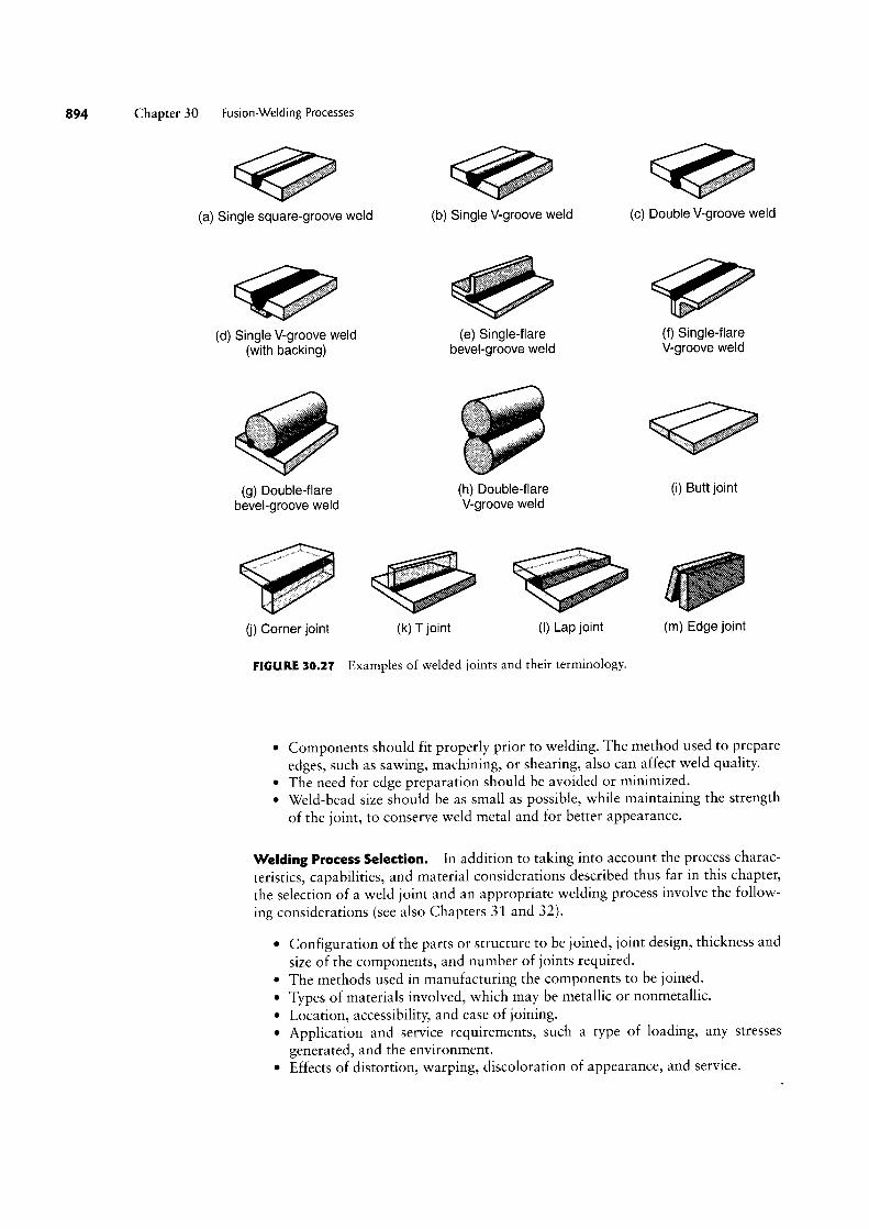
In describing individual welding processes, several examples were given concerningthe types of welds and joints produced and their applications in numerous consumerand industrial products of various designs. Typical types of joints produced by weld-ing, together with their terminology, are shown in Fig. 30.27. Standardized symbolscommonly used in engineering drawings to describe the types of welds are shown inFig. 30.28. These symbols identify the type of weld, the groove design, the weld sizeand length, the welding process, the sequence of operations, and other necessaryinformation.
The general design guidelines for welding may be summarized as follows, withsome examples given in Fig. 30.29 (various other types of joint design will be givenin Chapters 31 and 32):
° Product design should minimize the number of welds because, unless automated,welding can be costly.
° Weld location should be selected so as to avoid excessive stresses or stress con-centrations in the welded structure and for appearance.
° Weld location should be selected so as not to interfere with any subsequentprocessing of the joined components or with their intended use.
8 Chapter 30 Fusion-Welding Processes
(a) Single square-groove weld
(d) Single V-groove weld(with backing)
(g) Double-flarebevel-groove weld
(b) Single V-groove weld
.af(e) Single-flare
bevel-groove weld
3
geqfa’
(h) Double-flareV-groove weld
(c) Double V-groove weld
tree(f) Single-flareV-groove weld
\!Y-
(i) Butt joint
(j) Corner joint (k) joint (I) L p joint (m) dge joint
FIGURE 30.21 Examples of welded joints and their terminology.
° Components should fit properly prior to Welding. The method used to prepareedges, such as sawing, machining, or shearing, also can affect weld quality.
° The need for edge preparation should be avoided or minimized.° Weld-bead size should be as small as possible, While maintaining the strength
of the joint, to conserve Weld metal and for better appearance.
Welding Process Selection. In addition to taking into account the process charac-teristics, capabilities, and material considerations described thus far in this chapter,the selection of a weld joint and an appropriate welding process involve the follow-ing considerations (see also Chapters 31 and 32).
° Configuration of the parts or structure to be joined, joint design, thickness andsize of the components, and number of joints required.
° The methods used in manufacturing the components to be joined.° Types of materials involved, which may be metallic or nonmetallic.° Location, accessibility, and ease of joining.° Application and service requirements, such a type of loading, any stresses
generated, and the environment.° Effects of distortion, warping, discoloration of appearance, and service.

L _ i f _ " G . "G Pluse " G' ' G 'G I if if iF|é15hi_ _ ____ _____
Q I; U l | \/ l/ MJ IJ >l< QQ XXX l
Finish symbol
Comm" SVmb°| Groove angle or included angleRoot Opening, depth of fmmg of countersink for plug welds
f0|' P|UQ and Slot welds Length of weld in inches
Effecmfe throat § Pitch (center-to-center spacing)Depth of preparation of welds in inches
or size in inches F; Fieid We|d Symb0|
Reference line S Q E ;?}L P FWeld-all-around symbol
Specification, process T (E) "5 Q/ U’ @
or other reference 5 ifQ g A A B
Tail (omitted when / Qi § 3reference is not used) 5f_,`<7>
Arrow connects reference line to arrow side of joint.Basic weld symbol Use break as at A or B to signify that arrow is pointingor detail reference to the grooved member in bevel or J-grooved joints.
FIGURE 30.28 Standard identification and symbols for welds.
Poor Good Poor Good
Load
Load
(H) (D)
Cut not Deburredsquare Burr edge
/ / /(C) (dl
E Surface to be machined
(G) (fl
FIGURE 30.29 Sorne design guidelines for welds. Source: After ].G. Bralla.

896 Chapter 30 Fusion-Welding Processes
° Costs involved in edge preparation, joining, and postprocessing (includingmachining, grinding, and finishing operations).
° Costs of equipment, materials, labor and skills required, and the joiningoperation.
Table V1.1 gave the various characteristics of individual welding processes-characteristics that would serve as an additional guide to process selection. Refering tothis table, note that no single process has a high rating in all categories. For example,
° Arc welding, bolts, and riveting have high strength and reliability, but generallyare not suitable for joining small parts.
° Resistance welding has strength and applications for both small and largeparts. However, it is not easy to inspect visually for reliability, and resistancewelding has lower tolerances and reliability than other processes.
' Fasteners are useful for large parts and can be easy to inspect visually, but theyare costly and do not have much design variability.
° Adhesive bonding has high design variability. However, it has relatively lowstrength and is difficult to visually inspect for joint integrity.
EXAMPLE 30.3 Weld Design Selection
Three different types of weld designs are shown in
Fig. 30.30. In Fig. 30.3Oa, the two vertical joints canbe welded either externally or internally. Note thatfull-length external welding will take considerabletime and will require more weld material than thealternative design, which consists of intermittent in-ternal welds. Moreover, by the alternative method,the appearance of the structure is improved and dis~tortion is reduced.
In Fig. 30.30b, it can be shown that the designon the right can carry three times the moment M of
the one on the left. Note that both designs require thesame amount of weld metal and Welding time. InFig. 30.30c, the weld on the left requires about twicethe amount of weld material than does the design onthe right. Note that because more material must bemachined, the design on the left will require moretime for edge preparation, and more base metal willbe wasted as a result.
.... lirj prp, es.~. -lg Moment: M 3M ' ,~~ ,i~Continuous Intermittent '_i'Weld WGICIS J/ I I i > Weds
(H) (D)
Weld Base metal
VWSingle V-groove Double V-groove
(C)
FIGURE 30.30 Examples of weld designs used in Example 30.3.

SUMMARY
Oxyfuel-gas, arc, and high-energy-beam Welding are among the most commonlyused joining operations. Gas Welding uses chemical energy; to supply the neces-sary heat, arc and high-energy-beam welding use electrical energy instead.
In all of these processes, heat is used to bring the joint being Welded to a liquidstate. Shielding gases are used to protect the molten-Weld pool and the Weld areaagainst oxidation. Filler rods may or may not be used in oxyfuel-gas and arcWelding to fill the weld area.
The selection of a welding process for a particular operation depends on the work-piece material, its thickness and size, its shape complexity, the type of joint, thestrength required, and the change in product appearance caused by Welding.
A variety of Welding equipment is available-much of which is novv robotics andcomputer controlled with programmable features.The cutting of metals also can be done by processes whose principles are based onoxyfuel-gas and arc Welding. The cutting of steels occurs mainly through oxidation(burning). The highest temperatures for cutting are obtained by plasma-arc cutting.
The metallurgy of the welded joint is an important aspect of all welding processes,because it determines the strength and toughness of the joint. The Welded jointconsists of solidified metal and a heat-affected zone; each has a Wide variation inmicrostructure and properties, depending on the metals joined and on the fillermetals.
The metallurgy of the Welded joint is an important aspect of all welding processes,because it determines the strength and toughness of the joint. The Welded jointconsists of solidified metal and a heat-affected zone; each has a Wide variation inmicrostructure and properties, depending on the metals joined and on the fillermetals.
Discontinuities such as porosity, inclusions, incomplete vvelds, tears, surface dam-age, and cracks can develop in the weld zone. Residual stresses and relieving themalso are important considerations in Welding.
The weldability of metals and alloys depends greatly on their composition, thetype of Welding operation and process parameters employed, and the control ofwelding parameters.
General guidelines are available to help in the initial selection of suitable andeconomical Welding methods for a particular application.
KEY TERMS
Arc cuttingArc weldingAtomic-hydrogen weldingBase metalCarburizing flame
Coated electrodeConsumable electrodeDiscontinuitiesDrag linesElectrodeElectrogas welding
Electron-beam weldingElectroslag weldingFiller metalFluxFlux-cored arc weldingFusion weldingGas metal-arc weldingGas tungsten-arc weldingHeat-affected zoneInclusionsjoining
KerfKeyhole techniqueLaser-beam weldingNeutral flameNonconsumable electrodeOxidizing flameOxyfuel-gas cuttingOxyfuel-gas weldingPlasma-arc weldingPolarityPorosity
Key Terms 897
Reducing flameResidual stressesShielded metal-arc weldingSlag
Stick weldingSubmerged-arc weldingTears
Weld profileWeld metalWeldabilityWelding gun

898 Chapter 30 Fusion-Welding Processes
BIBLIOGRAPHY
ASM Handbook, Vol. 6: Welding, Brazing, and Soldering,ASM International, 1993.
Bowditch, WA., and Bowditch, K.E., Welding TechnologyFundamentals, Goodheart-Willcox, 1997.
Cary, H.B., and Helzer, S., Modern Welding Technology,6th ed., Prentice Hall, 2004.
Croft, D., Heat Treatment of Welded Structures, WoodheadPublishing, 1996.
Davies, A.C., The Science and Practice of Welding, 10th ed.
(2 vols.), Cambridge University Press, 1993.Duley, WW, Laser Welding, Wiley, 1999.Evans, G.M., and Bailey, N., Metallurgy of Basic Weld
Metal, Woodhead Publishing, 1997.Hicks, ].G., Welded _Ioint Design, 2nd ed., Abington, 1997.Houldcroft, P.T., Welding and Cutting: A Guide to Fusion
Welding and Associated Cutting Processes, IndustrialPress, 2001.
Jeffus, L.F., Welding: Principles and Applications, 6th ed.,Delmar Publishers, 2007.
REVIEW QUESTIONS
Kou, S., Welding Metallurgy, 2nd ed., Wiley, 2003.Lippold, ].C., and Kotecki, D.]., Welding Metallurgy and
Weldability of Stainless Steels, Wiley, 2005.Minnick, WH., Gas Metal Arc Welding Handbook, Goodheart-
Willeox, 2000.Mouser, ].D., Welding Codes, Standards, and Specifications,
McGraw-Hill, 1997.Schultz, H., Electron Beam Welding, Woodhead Publishing,
1994.Steen, WM., Laser Material Processing, 3rd ed., Springer,
2003.Welding Handbook, 9th ed. (3 vols.), American Welding
Society, 2007.Welding Inspection Handbook, American Welding Society,
2000.Weman, K., Welding Process Handbook, CRC Press, 2003.
30.1. Describe fusion as it relates to welding operations.
30.2. Explain the features of neutralizing, reducing, andoxidizing flames. Why is a reducing flame so called?
30.3. Explain the basic principles of arc-welding processes.
30.4. Why is shielded metal-arc welding a commonly usedprocess? Why is it also called stick welding?
30.5. Describe the functions and characteristics of elec-
trodes. What functions do coatings have? How are electrodesclassified?
30.6. What are the similarities and differences between con-sumable and nonconsumable electrodes?
30.7. Explain how cutting takes place when an oxyfuel-gastorch is used. How is underwater cutting done?
QUALITATIVE PROBLEMS
30.8. What is the purpose of flux? Why is it not needed in
gas tungsten-arc welding?
30.9. What is meant by weld quality? Discuss the factorsthat influence it.
30.10. How is Weldability defined?
30.1 1. Why are welding electrodes generally coated?
30.12. Describe the common types of discontinuities in
welded joints.
30.13. What types of destructive tests are performed onwelded joints?
30.14. Explain the reasons that so many different weldingprocesses have been developed over the years.
30.15. Explain why some joints may have to be preheatedprior to welding.
30.16. Describe the role of filler metals in welding.
30.17. What is the effect of the thermal conductivity of theworkpiece on kerf width in oxyfuel-gas cutting? Explain.
30.18. Describe the differences between oxyfuel-gas cuttingof ferrous and of nonferrous alloys. Which properties aresignificant?
30.19. Could you use oxyfuel-gas cutting for a stack of sheetmetals? (Note: For stack cutting, see Fig. 24.25e.) Explain.
30.20. What are the advantages of electron-beam and laser-
beam welding compared with arc welding?
30.21. Describe the methods by which discontinuities in
welding can be avoided.30.22. Explain the significance of the stiffness of the com-ponents being welded on both weld quality and part shape.
30.23. Comment on the factors that influence the size of thetwo weld beads shown in Fig. 30.14.
30.24. Which of the processes described in this chapter arenot portable? Can they be made so? Explain.
30.25. Describe your observations concerning the contentsof Table 30.1.
30.26. What determines whether a certain welding processcan be used for workpieces in horizontal, vertical, or upside-down positions-or, for that matter, in any position? (SeeTable 30.1.) Explain and give examples of appropriateapplications.30.27. Comment on the factors involved in electrode selec-
tion in arc-welding processes.
30.28. In Table 30.1, the column on the distortion of weldedcomponents is ordered from lowest distortion to highest.
Synthesis, Design, and Projects 899
Explain why the degree of distortion varies among differentwelding processes.
30.29. Explain the significance of residual stresses in weldedstructures.
30.30. Rank the processes described in this chapter in termsof (a) cost and (b) weld quality.
30.31. Must the filler metal be made of the same composi-tion as the base metal that is to be welded? Explain.
30.32. Describe your observations concerning Fig. 30.18.
30.33. If the materials to be welded are preheated, is thelikelihood for porosity increased or decreased? Explain.
QUANTITATIVE PROBLEMS
30.34. Plot the hardness in Fig. 30.18d as a function of thedistance from the top surface, and discuss your observations.
|]30.35. A welding operation will take place on carbonsteel. The desired welding speed is around 20 mm/s. If an arc-welding power supply is used with a voltage of 12 \L whatcurrent is needed if the weld width is to be 5 mm?
SYNTHESIS, DESIGN, AND PROJECTS
30.36. In Fig. 30.24b, assume that most of the top por-tion of the top piece is cut horizontally with a sharp saw. Theresidual stresses will now be disturbed and the part willchange its shape, as was described in Section 2.11. For thiscase, how do you think the part will distort: curved down-ward or upward? Explain. (See also Fig. 2.30d.)
30.37. Comment on workpiece size and shape limitationsfor each of the processes described in this chapter.
30.38. Review the types of welded joints shown in Fig. 30.27and give an application for each.
30.39. Comment on the design guidelines given in varioussections of this chapter.
30.40. You are asked to inspect a welded structure for a
critical engineering application. Describe the procedure thatyou would follow in order to determine the safety of thestructure.
30.4I. Discuss the need for, and the role of, work-holdingdevices in the welding operations described in this chapter.
30.42. Make a list of welding processes that are suitable forproducing (a) butt joints, where the weld is in the form of a
line or line segment, (b) spot welds, and (c) both butt jointsand spot welds. Comment on your observations.
30.43. Explain the factors that contribute to the differencesin properties across a welded joint.
30.44. Explain why preheating the components to be weldedis effective in reducing the likelihood of developing cracks.
30.45. Review the poor and good joint designs shown in
Fig. 30.29, and explain why they are labeled so.
30.46. In building large ships, there is a need to weld thickand large sections of steel together to form a hull. Considereach of the welding operations discussed in this chapter, and
list the benefits and drawbacks of that particular joiningoperation for this application.
30.47. Inspect various parts and components in (a) an auto-mobile, (b) a major appliance, and (c) kitchen utensils, andexplain which, if any, of the processes described in this chap-ter has been used in joining them.
30.48. Comment on whether there are common factors thataffect the weldability, castability, formability, and machin-ability of metals, as described in various chapter of this book.Explain with appropriate examples.
30.49. If you find a flaw in a welded joint during inspection,how would you go about determining whether or not theflaw is significant?
30.50. Lattice booms for cranes are constructed from ex-truded cross sections (see Fig. 15 .2) that are welded together.Any warpage that causes such a boom to deviate fromstraightness will severely reduce its lifting capacity. Conduct a
literature search on the approaches used to minimize distor-tion due to welding and how to correct it, specifically in theconstruction of lattice booms.
30.5 I. A common practice in repairing expensive broken orworn parts (such as may occur when a fragment is brokenfrom a forging) is to fill the area with layers of weld beadsand then to machine the part back to its original dimensions.Make a list of the precautions that you would suggest tosomeone who uses this approach.

ERPTACHunwuwumuwuuuuww0
T)'I'T'TI"`><TTTTTTTT0-'sa-5wN-3|e:o~|o~v\-hwN- .
UZ"'WU"WI551""'U|""W""'Wh'
E-E-u:.;§_§`§~§mFor--9g=,;><~=-§oo?,
~‘la”=n~”~a='~”’=u2=a~‘l”-P-;-,ais
OU;-,,,g~_~1".¢',_.ow..~¢,,.og5',,,...,_‘<-°crusno-r--mm:lf
:..m¢-\:_.3--:ior: 2-;=~<éggv=g5g_egggg:wan_._:|""_.
Q pam2:‘5lllmw~§nETC~o
-o*°‘°n»\°oo-:E:"':»;§2§g,';"°g`o"~g_m§E:§2vn=
aiwe!N25to-vu._.€_.&E=ENo...Dn.-.--ono~¢v5=....°°--=¢
0“UQ5-55_7ENN::I9-°
§`f»9,Wfwwaw:-bagQ
U|N
900
1 Solid-State WeldingProcesses
Pistons 9 I 7
° This chapter describes an important family of joining processes in which the
workpieces do not undergo a phase change and no filler metal is used; if heat is
used, it is not externally applied, but instead is generated internally-for exam-ple, with friction.
‘ The chapter begins with a discussion of cold welding, followed by ultrasonicwelding and the various forms of friction-welding processes.
° Resistance welding is then described, followed by explosion welding and diffu-
sion bonding; these three processes have unique capabilities and applicationssuitable for a wide variety of materials and can be automated for large-scaleproduction.
° The chapter also examines special capabilities of diffusion bonding combinedwith superplastic forming.
° Finally, economic considerations in welding are discussed.
3 |.l Introduction
This chapter describes solid-state welding processes, in which joining takes place with-out fusion at the interface of the two parts to be welded. Unlike the situation with the
fusion-welding processes described in Chapter 30, in solid-state welding no liquid or
molten phase is present in the joint. The principle of solid-state welding is demon-
strated best with the following example: If two clean surfaces are brought into close
contact with each other under sufficient pressure, they form bonds and produce a joint.
To form a strong bond, it is essential that the interface be free of oxide films, residues,
metalworking fluids, other contaminants, and even adsorbed layers of gas.
Solid-state bonding involves one or more of the following phenomena:
° Diffusion: The transfer of atoms across an interface; thus, applying external
heat improves the strength of the bond between the two surfaces being joined,as occurs in diffusion bonding. Heat may be generated internally by friction(as utilized in friction welding), through electrical-resistance heating (as in
resistance-welding processes, such as spot welding), and externally by induc-tion heating (as in butt-welding tubes).
° Pressure: The higher the pressure, the stronger is the interface (as in roll bond-ing and explosion welding), where plastic deformation also occurs. Pressure

Section 31.2 Cold Welding and Roll Bonding 90|
and resistance heating may be combined, as in flash welding, stud welding,and resistance projection welding.
° Relative interfacial movements: When movements of the contacting surfaces(faying surfaces) occur (as in ultrasonic welding), even very small amplitudeswill disturb the mating surfaces, break up any oxide films, and generate new,clean surfaces-thus improving the strength of the bond.
Most of the joining processes outlined here are now automated by robotics,vision systems, sensors, and adaptive and computer controls (see Part IX) for costreduction, consistency, reliability of weld quality, and higher productivity. The costsinvolved in the joining process are outlined in Section 31.8.
3I.2 Cold Welding and Roll Bonding
In cold welding (CW), pressure is applied to the workpieces through dies or rolls.Because of the plastic deformation involved, it is necessary that at least one (butpreferably both) of the mating parts be ductile. Prior to welding, the interface is
degreased, wire brushed, and wiped to remove oxide smudges. Cold welding can beused to join small workpieces made of soft, ductile metals. Applications include wirestock and electrical connections.
During the joining of two dissimilar metals that are mutually soluble, brittleintermetallic compounds may form (Section 4.2.2); these will produce a weak andbrittle joint. An example occurs in the bonding of aluminum and steel, where abrittle intermetallic compound is formed at the interface. The best bond strength is
obtained with two similar materials.
Roll Bonding. The pressure required for welding can be applied through a pairof rolls (Fig. 31.1); this process is called roll bonding or roll welding (ROW).Developed in the 1960s, roll bonding is used for manufacturing some U.S. coins (seeExample 31.1). The process can be carried out at elevated tempera-tures (loot roll bonding). Surface preparation is important for interfa-cial strength.
Typical examples are the cladding of (a) pure aluminum overprecipitation-hardened aluminum-alloy sheet (Alclad) and (b) stain-less steel over mild steel (for corrosion resistance). A common appli-cation of roll bonding is the production of bimetallic strips forthermostats and similar controls using two layers of materials withdifferent thermal-expansion coefficients. Bonding in only selected re-
Cladding metal
I Base metal
Rolls
FIGURE 3| I Schematic illustration of thegions in the interface can be achieved by depositing a parting agent,such as graphite or ceramic, called stop-off (see Section 31.7). roll bonding, or cladding, process.
EXAMPLE 3l.l Roll Bonding of the U.S. Quarter
The technique used for manufacturing composite U.S.quarters is the roll bonding of two outer layers of75% Cu-25% Ni (cupronickel), where each layer is1.2 mm thick, with an inner layer of pure copper5.1 mm thick. To obtain good bond strength, the fay-ing surfaces are cleaned chemically and wire brushed.First, the strips are rolled to a thickness of 2.29 mm;a second rolling operation reduces the thickness to1.36 mm. The strips thus undergo a total reduction in
thickness of 82%.Because volume constancy is maintained in
plastic deformation, there is a major increase in thesurface area between the layers, and it causes the gen-eration of clean interfacial surfaces. This extension insurface area under the high pressure of the rolls,combined with the solid solubility of nickel in copper(see Section 4.2..1), produces a strong bond.
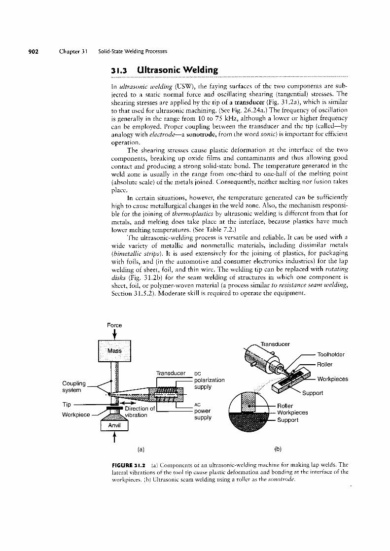
2 Chapter 31 Solid-State Welding Processes
3 |.3 Ultrasonic Welding
In ultrasonic welding (USW), the faying surfaces of the two components are sub-
jected to a static normal force and oscillating shearing (tangential) stresses. Theshearing stresses are applied by the tip of a transducer (Fig. 31.2a), which is similarto that used for ultrasonic machining. (See Fig. 26.24a.) The frequency of oscillationis generally in the range from 10 to 75 kHz, although a lower or higher frequencycan be employed. Proper coupling between the transducer and the tip (called-byanalogy with electrode-a sonotrode, from the word sonic) is important for efficientoperation.
The shearing stresses cause plastic deformation at the interface of the two
components, breaking up oxide films and contaminants and thus allowing goodcontact and producing a strong solid-state bond. The temperature generated in theweld zone is usually in the range from one-third to one-half of the melting point(absolute scale) of the metals joined. Consequently, neither melting nor fusion takesplace.
In certain situations, however, the temperature generated can be sufficientlyhigh to cause metallurgical changes in the weld zone. Also, the mechanism responsi-ble for the joining of tloerrnoplastics by ultrasonic welding is different from that formetals, and melting does take place at the interface, because plastics have muchlower melting temperatures. (See Table 7.2.)
The ultrasonic-welding process is versatile and reliable. It can be used with a
wide variety of metallic and nonmetallic materials, including dissimilar metals(biinetallic strips). It is used extensively for the joining of plastics, for packagingwith foils, and (in the automotive and consumer electronics industries) for the lap
welding of sheet, foil, and thin wire. The welding tip can be replaced with rotatingdisks (Fig. 31.2b) for the seam welding of structures in which one component is
sheet, foil, or polymer-woven material (a process similar to resistance searn welding,Section 31.5.2). Moderate skill is required to operate the equipment.
Force
7 jiijij. s- Transducer :tis ‘ Toolholder
Holler
(5Transducer oc “
Coupling polarization ~~s~rsi"’ Workpieces
System ` rrrr Supply % mi Su ort pp
<Di;ction of power RollerWorkpiece ibration Suppw \é\/Loyggjeces
-vil(H) (b)
FIGURE 3l.2 (a) Components of an ultrasonic-welding machine for making lap welds. Thelateral vibrations of the tool tip cause plastic deformation and bonding at the interface of the
workpieces. (b) Ultrasonic seam welding using a roller as the sonotrode.

Section 31 4 Friction Welding
3 |.4 Friction Welding
In the joining processes described thus far, the energy required for welding (typicallychemical, electrical, or ultrasonic energy) is supplied from external sources. Infriction welding (FRW), the heat required for welding is generated through (as thename implies) friction at the interface of the two components being joined. You candemonstrate the significant rise in temperature caused by friction by rubbing yourhands together or by sliding down a rope rapidly.
In friction welding, developed in the 1940s, one of the workpiece componentsremains stationary while the other is placed in a chuck or collet and rotated at a
high constant speed. The two members to be joined are then brought into contactunder an axial force (Fig. 31.3). The surface speed of the rotating parts may be as
high as 900 m/min. After sufficient contact is established, the rotating member is
brought to a quick stop (so that the weld is not destroyed by shearing) while theaxial force is increased. Oxides and other contaminants at the interface are removedby the radially outward movement of the hot metal at the interface.
The rotating member must be clamped securely to the chuck or collet to resistboth torque and axial forces without slipping. The pressure at the interface and theresulting friction produce sufficient heat for a strong joint to form.
The weld zone usually is confined to a narrow region; its size depends on thefollowing parameters:
° Amount of heat generated.° Thermal conductivity of the materials.° Mechanical properties of the materials being joined at elevated temperatures.
The shape of the welded joint depends on the rotational speed and on the axialpressure applied (Fig. 31.4). These factors must be controlled to obtain a uniform, _Force Beginning of flash
* 2' ForceSpeed increased
5O1 3.C2'03 FlashU)
ifm Force 4_o“_
'cianGJ
(3 Upset ‘eww Total upset length
>Time
FIGURE 31.3 Sequence of operations in the friction-welding process: (1) The part on the left
is rotated at high speed; (2) The part on the right is brought into contact with the part on theleft under an axial force; (3) The axial force is increased, and the part on the left stopsrotating; flash begins to form; (4) After a specified upset length or distance is achieved, theweld is completed. The upset length is the distance the two pieces move inward duringwelding after their initial contact; thus, the total length after welding is less than the sum ofthe lengths of the two pieces. The flash subsequently can be removed by machining orgrinding.
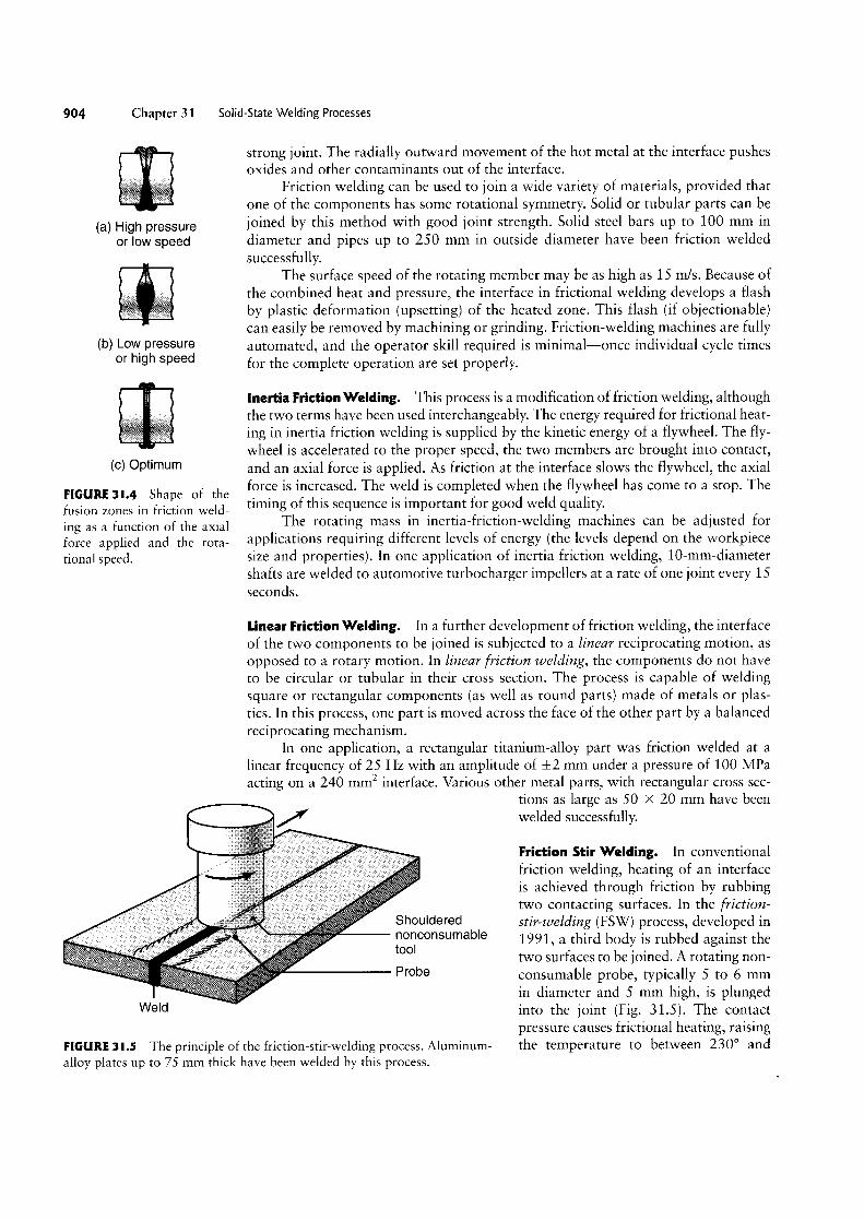
904 Chapter 3 1
I(a) High pressure
or low speed
J;m
(b) Low pressureor high speed
il
(C) Optimum
FIGURE 3l.4 Shape of thefusion zones in friction weld-ing as a function of the axialforce applied and the rota-tional speed.
Solid-State Welding Processes
strong joint. The radially outward movement of the hot metal at the interface pushesoxides and other contaminants out of the interface.
Friction welding can be used to join a wide variety of materials, provided thatone of the components has some rotational symmetry. Solid or tubular parts can bejoined by this method with good joint strength. Solid steel bars up to 100 mm in
diameter and pipes up to 250 mm in outside diameter have been friction weldedsuccessfully.
The surface speed of the rotating member may be as high as 15 m/s. Because ofthe combined heat and pressure, the interface in frictional welding develops a flashby plastic deformation (upsetting) of the heated zone. This flash (if objectionable)can easily be removed by machining or grinding. Friction-welding machines are fullyautomated, and the operator skill required is minimal-once individual cycle timesfor the complete operation are set properly.
Inertia Friction Welding. This process is a modification of friction welding, althoughthe two terms have been used interchangeably. The energy required for frictional heat-ing in inertia friction welding is supplied by the kinetic energy of a flywheel. The fly-
wheel is accelerated to the proper speed, the two members are brought into contact,and an axial force is applied. As friction at the interface slows the flywheel, the axialforce is increased. The weld is completed when the flywheel has come to a stop. Thetiming of this sequence is important for good weld quality.
The rotating mass in inertia-friction-welding machines can be adjusted forapplications requiring different levels of energy (the levels depend on the workpiecesize and properties). In one application of inertia friction welding, 10-mm-diametershafts are welded to automotive turbocharger impellers at a rate of one joint every 15
seconds.
Linear Friction Welding. In a further development of friction welding, the interfaceof the two components to be joined is subjected to a linear reciprocating motion, asopposed to a rotary motion. In linear friction welding, the components do not haveto be circular or tubular in their cross section. The process is capable of weldingsquare or rectangular components (as well as round parts) made of metals or plas-tics. In this process, one part is moved across the face of the other part by a balancedreciprocating mechanism.
In one application, a rectangular titanium-alloy part was friction welded at a
linear frequency of 25 Hz with an amplitude of i2 mm under a pressure of 100 MPaacting on a 240 mm; interface. Various other metal parts, with rectangular cross sec-
tions as large as 50 >< 20 mm have been / welded successfully. Q --“` _ Friction Stir Welding. In conventional friction welding, heating of an interface " is achieved through friction by rubbing two contacting surfaces. In the friction- Shouldered stir-welding (FSW) process, developed in »'ee Poooqconsumable 1991, a third body is rubbed against the ../ gg two surfaces to be joined. A rotating non-; "i' Probe consumable probe, typically 5 to 6 mm
W in diameter and 5 mm high, is plungedGld
FIGURE 3 l.5 The principle of the friction-stir-welding process. Aluminum-
into the joint (Fig. 31.5). The contactpressure causes frictional heating, raisingthe temperature to between 230° and
alloy plates up to 75 mm thick have been welded by this process.

Section 3 1.5
260°C. The probe at the tip of the rotating tool forces mixing (or stirring) of the mate-rial in the joint.
Materials such as aluminum, copper, steel, and titanium have been welded suc-cessfully, and developments are taking place to extend FSW applications to polymersand composite materials. The process is now being applied to aerospace, automotive,shipbuilding, and military vehicles, using sheet or plates. With developments inrotating-tool design, other possible applications include inducing microstructuralchanges, refining grain in materials, and improving localized toughness in castings.
The welding equipment can be a conventional, vertical-spindle milling machine(Fig. 24.15b), and the process is relatively easy to implement. The thickness of thewelded material can be as little as 1 mm and as much as 50 mm welded in a singlepass. Welds produced by friction stir welding have high quality, minimal pores, and auniform material structure. The welds are produced with low heat input and there-fore low distortion and little microstructural changes. No shielding gas or surfacecleaning is required.
3 l.5 Resistance Welding
The category of resistance welding (RW) covers a number of processes in which theheat required for welding is produced by means of electrical resistance across thetwo components to be joined. These processes have major advantages, such as notrequiring consumable electrodes, shielding gases, or flux.
The heat generated in resistance welding is given by the general expression
H = I2Rt, (31.1)
where
H = Heat generated in joules (watt-seconds)I = Current (in amperes)
R = Resistance (in ohms)t = Time of current flow (in seconds).
Equation (31.1) is often modified so that it represents the actual heat energy avail-able in the weld by including a factor K, which denotes the energy losses throughconduction and radiation. The equation then becomes
H = I2RtK, (31.2)
where the value of K is less than unity.The total resistance is the sum of the following properties (see Fig. 31.6):
a. Resistances of the electrodes;
b. Electrode-workpiece contact resistance;
c. Resistances of the individual parts to be welded;
d. Contact resistance between the two workpieces to be joined (fa)/ing surfaces).
The actual temperature rise at the joint depends on the specific heat and the ther-mal conductivity of the metals to be joined. For example, metals such as aluminumand copper have high thermal conductivity, so they require high heat concentrations.Similar or dissimilar metals can be joined by resistance welding. The magnitude of thecurrent in resistance-welding operations may be as high as 100,000 A, but the voltageis typically only 0.5 to 10 V
Resistance Welding
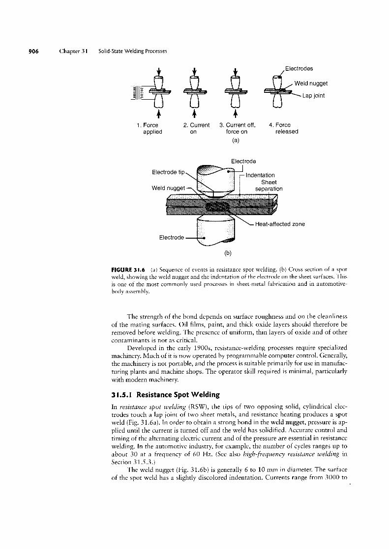
0 Chapter 31 Solid-State Welding Processes
Electrodes' Weld nugget " ""”"` " ""i Lap ioim
1. Force 2. Current 3. Current off, 4. Forceapplied on force on released
(al
Electrode
Electrode tip ' ‘mentation
~ SheetWeld UUQQGT `_ F? separation c.... ..”.. ............. .. ......... - ....... ....... .,,,
Heat-affected zone
Electrode 'AhV (bl
FIGURE 3I.6 (a) Sequence of events in resistance spot welding. (b) Cross section of a spotweld, showing the weld nugget and the indentation of the electrode on the sheet surfaces. Thisis one of the most commonly used processes in sheet-metal fabrication and in automotive-body assembly.
The strength of the bond depends on surface roughness and on the cleanlinessof the mating surfaces. Oil films, paint, and thick oxide layers should therefore beremoved before welding. The presence of uniform, thin layers of oxide and of othercontaminants is not as critical.
Developed in the early 1900s, resistance-welding processes require specializedmachinery. Much of it is now operated by programmable computer control. Generally,the machinery is not portable, and the process is suitable primarily for use in manufac-turing plants and machine shops. The operator skill required is minimal, particularlywith modern machinery.
3 I.5.l Resistance Spot Welding
In resistance spot welding (RSW), the tips of two opposing solid, cylindrical elec-
trodes touch a lap joint of two sheet metals, and resistance heating produces a spotweld (Fig. 31.6a). In order to obtain a strong bond in the weld nugget, pressure is ap-plied until the current is turned off and the weld has solidified. Accurate control andtiming of the alternating electric current and of the pressure are essential in resistancewelding. In the automotive industry, for example, the number of cycles ranges up toabout 30 at a frequency of 60 Hz. (See also high-frequency resistance welding in
Section 31.5.3.)The weld nugget (Fig. 31.6b) is generally 6 to 10 mm in diameter. The surface
of the spot weld has a slightly discolored indentation. Currents range from 3000 to

Section 3 1.5
40,000 A. The current level depends on the materials being welded and on theirthicknesses. For example, the current is typically 10,000 A for steels and 13,000 Afor aluminum. Electrodes generally are made of copper alloys and must have suffi-cient electrical conductivity and hot strength to maintain their shape.
Spot welding is the simplest and most commonly used resistance~weldingprocess. Welding may be performed by means of single (most common) or multiplepairs of electrodes (as many as a hundred or more), and the required pressure is
supplied through mechanical or pneumatic means. Rocker-arm-type spot-weldingmachines normally are used for smaller parts; press-type machines are used forlarger workpieces. The shape and surface condition of the electrode tip and theaccessibility of the site are important factors in spot welding. A variety of electrodeshapes are used to spot-weld areas that are difficult to reach (Fig. 31.7).
Spot welding is used widely for fabricating sheet-metal parts. Examples rangefrom attaching handles to stainless-steel cookware (Fig. 31.8a) to spot-welding muf-flers (Fig. 31.8b) and large sheet-metal structures. Modern spot-welding equipmentis computer controlled for optimum timing of current and pressure; its spot-weldingguns are manipulated by programmable robots (Fig. 31.8c). Automobile bodies canhave as many as 10,000 spot welds; they are welded at high rates with the use ofmultiple electrodes (see Fig. 1.10 in the General Introduction).
Testing Spot Welds. Spot-welded joints may be tested for weld-nugget strength bymeans of the following techniques (Fig. 31.9):
° Tension-shear° Cross-tension° Twist° Peel.
f. .>
(5) (D)
(C)
FIGURE 3I.8 Spot-welded (a) cookware and (b) muffler. (c) An automated spot-weldingmachine. The welding tip can move in three principal directions. Sheets as large as2.2 X 0.55 m can be accommodated in this machine with proper workpiece supports.Source: Courtesy of Taylor-Winfield Corporation.
Resistance Welding 907
QQ iiiiii ililii Electrodes
QMWorkpiece
(H)
1%
li Workpiece
(D)
FIGURE 3 I.1 Two electrodedesigns for easy access to thecomponents to be welded.
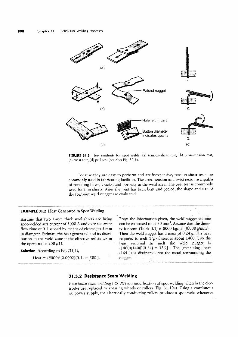
08 Chapter 31 Solid-State Welding Processes
\. \i(H)
* g Ftaised nugget
<b> 2-
Hole left in part Button diameter ii?i?% `;;ii0 indicates quality
(C) (Ol)
FIGURE 3l.9 Test methods for spot welds: (a) tension-shear test, (b) cross-tension test,
(C) twist test, (d) peel test (see also Fig. 32.9).
Because they are easy to perform and are inexpensive, tension-shear tests are
commonly used in fabricating facilities. The cross-tension and twist tests are capableof revealing flaws, cracks, and porosity in the Weld area. The peel test is commonlyused for thin sheets. After the joint has been bent and peeled, the shape and size of
the torn-out weld nugget are evaluated.
EXAMPLE 3 |.2 Heat Generated in Spot Welding
Assume that two 1-mm thick steel sheets are beingspot-welded at a current of 5000 A and over a currentflow time of 0.1 second by means of electrodes 5 mmin diameter. Estimate the heat generated and its distri-bution in the weld zone if the effective resistance in
the operation is 200 /JLQ.
Solution According to Eq. (31.1),
Heat = (5000)2(0.00O2)(0.1) = 500].
From the information given, the weld-nugget volumecan be estimated to be 30 mm3. Assume that the densi»
ty for steel (Table 3.1) is 8000 kg/IT13 (0.008 g/mm3).Then the weld nugget has a mass of 0.24 g. The heatrequired to melt 1 g of steel is about 1400 _l, so theheat required to melt the weld nugget is
(1400)(1400)(0.24) = 336 ]. The remaining heat(164 j) is dissipated into the metal surrounding thenugget.
3 l.5.2 Resistance Seam Welding
Resistance seam welding (RSEW) is a modification of spot welding wherein the elec-
trodes are replaced by rotating wheels or rollers (Fig. 31.10a). Using a continuousAC power supply, the electrically conducting rollers produce a spot weld whenever

Section 31.5 Resistance Welding 0
Electrode wheels'A Electrode wheels _1 Seam z:=' Weld nuggets We|d Sheet "" Weld f t x -Q -Q
E §
(2) (D) (C)
FIGURE 3l.l0 (a) Seam-welding process in which rotating rolls act as electrodes.(b) Overlapping spots in a seam weld. (c) Roll spot welds and (d) Mash seam welding.
the current reaches a sufficiently high level in the AC cycle. With a high enoughfrequency or slow enough traverse speed, these spot welds actually overlap into acontinuous seam and produce a joint that is liquid tight and gastight (Fig. 31.10b).
In roll spot welding, current to the rollers is applied only intermittently,resulting in a series of spot welds at specified intervals along the length of the seam(Fig. 31.10c). In mash seam welding (Fig. 31.1Od), the overlapping welds are aboutone to two times the sheet thickness, and the welded seam thickness is only about90% of the original sheet thickness. This process is also used in producing tailor-welded sheet-metal blanks, which can be made by laser welding as well (seeSection 16.2.2).
The RSEW process is used to make the longitudinal (side) seam of cans (forhousehold products) mufflers, gasoline tanks, and other containers. The typicalwelding speed is 1.5 m/min for thin sheets.
3 l.5.3 High-frequency Resistance Welding
High-frequency resistance welding (HFRW) is similar to seam welding, except thathigh-frequency current (up to 450 kHz) is employed. A typical application is theproduction of butt-welded tubing or pipe where the current is conducted throughtwo sliding contacts (Fig. 31.11a) to the edges of roll-formed tubes. The heatededges then are pressed together by passing the tube through a pair of squeeze rolls.Any flash formed is then trimmed off.
Contacts High-frequency coil
Vee Apex gg Apex ” Current r Current Squeeze iiiiiivii *W S
Tube travel || ` queeze f° (al (D)
FIGURE 3l.l I Two methods of high-frequency continuous butt welding of tubes.
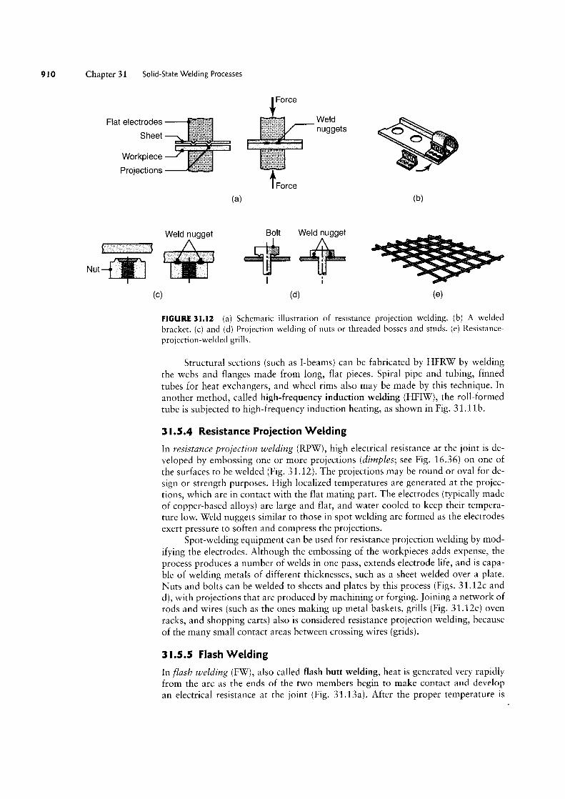
0 Chapter 31 Solid-State Welding Processes
Force
Flat electrodes Weld &Sheet nuggets X __ s $5
Workpiece Projections *Q 4
Force
(3) (b)
Weld nugget B0ll Weld nugget
51 :3s _ sss sssssss _...r ii l
(C) (Cl) le)
FIGURE 3l.l2 (a) Schematic illustration of resistance projection welding. (b) A weldedbracket. (c) and (d) Projection welding of nuts or threaded bosses and studs. (e) Resistance-
projection-welded grills.
Structural sections (such as I-beams) can be fabricated by HFRW by weldingthe webs and flanges made from long, flat pieces. Spiral pipe and tubing, finnedtubes for heat exchangers, and wheel rims also may be made by this technique. In
another method, called high-frequency induction welding (HFIW), the roll-formedtube is subjected to high-frequency induction heating, as shown in Fig. 31.11b.
3 l.5.4 Resistance Projection Welding
In resistance projection welding (RPW), high electrical resistance at the joint is de-veloped by embossing one or more projections (dimples; see Fig. 1636) on one of
the surfaces to be welded (Fig. 3l.l2). The projections may be round or oval for de-
sign or strength purposes. High localized temperatures are generated at the projec-tions, which are in contact with the flat mating part. The electrodes (typically madeof copper-based alloys) are large and flat, and water cooled to keep their tempera-ture low. Weld nuggets similar to those in spot welding are formed as the electrodesexert pressure to soften and compress the projections.
Spot-welding equipment can be used for resistance projection welding by mod-
ifying the electrodes. Although the embossing of the workpieces adds expense, theprocess produces a number of welds in one pass, extends electrode life, and is capa-ble of welding metals of different thicknesses, such as a sheet welded over a plate.Nuts and bolts can be welded to sheets and plates by this process (Figs. 31.12c andd), with projections that are produced by machining or forging. joining a network ofrods and wires (such as the ones making up metal baskets, grills (Fig. 3l.12e) ovenracks, and shopping carts) also is considered resistance projection welding, becauseof the many small contact areas between crossing wires (grids).
3 l.5.5 Flash Welding
In flash welding (FW), also called flash butt welding, heat is generated very rapidlyfrom the arc as the ends of the two members begin to make contact and developan electrical resistance at the joint (Fig. 31.13a). After the proper temperature is
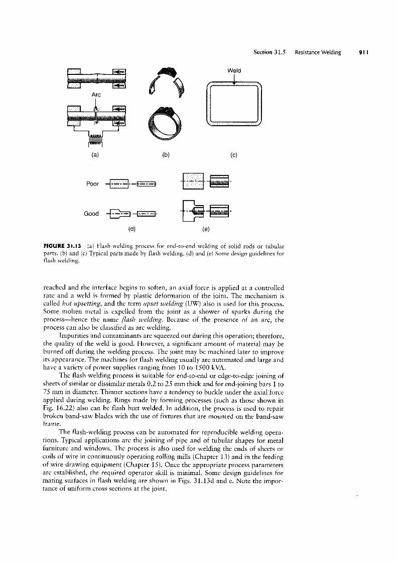
Q Weld ‘~~; KArc i"i dw, KZ
l""""l
(5) (b) (C)
Poor -E-I-'_§~El
Good -E§E_j-|§- ~(Ol) (G)
Section 31.5 Resistance Welding
FIGURE 3|.I3 (a) Flash-welding process for end-to-end welding of solid rods or tubularparts. (b) and (c) Typical parts made by flash welding. (d) and (e) Some design guidelines forflash welding.
reached and the interface begins to soften, an axial force is applied at a controlledrate and a weld is formed by plastic deformation of the joint. The mechanism is
called hot upsetting, and the term upset welding (UW) also is used for this process.Some molten metal is expelled from the joint as a shower of sparks during theprocess-hence the name flash welding. Because of the presence of an arc, theprocess can also be classified as arc welding.
impurities and contaminants are squeezed out during this operation; therefore,the quality of the weld is good. However, a significant amount of material may beburned off during the welding process. The joint may be machined later to improveits appearance. The machines for flash welding usually are automated and large andhave a variety of power supplies ranging from 10 to 1500 kVA.
The flash-welding process is suitable for end-to-end or edge-to-edge joining ofsheets of similar or dissimilar metals 0.2 to 25 mm thick and for end-joining bars 1 to75 mm in diameter. Thinner sections have a tendency to buckle under the axial forceapplied during welding. Rings made by forming processes (such as those shown inFig. 1622) also can be flash butt welded. In addition, the process is used to repairbroken band-saw blades with the use of fixtures that are mounted on the band-sawframe.
The flash-welding process can be automated for reproducible welding opera-tions. Typical applications are the joining of pipe and of tubular shapes for metalfurniture and windows. The process is also used for welding the ends of sheets orcoils of wire in continuously operating rolling mills (Chapter 13) and in the feedingof wire-drawing equipment (Chapter 15). Once the appropriate process parametersare established, the required operator skill is minimal. Some design guidelines formating surfaces in flash welding are shown in Figs. 31.13d and e. Note the impor-tance of uniform cross sections at the joint.
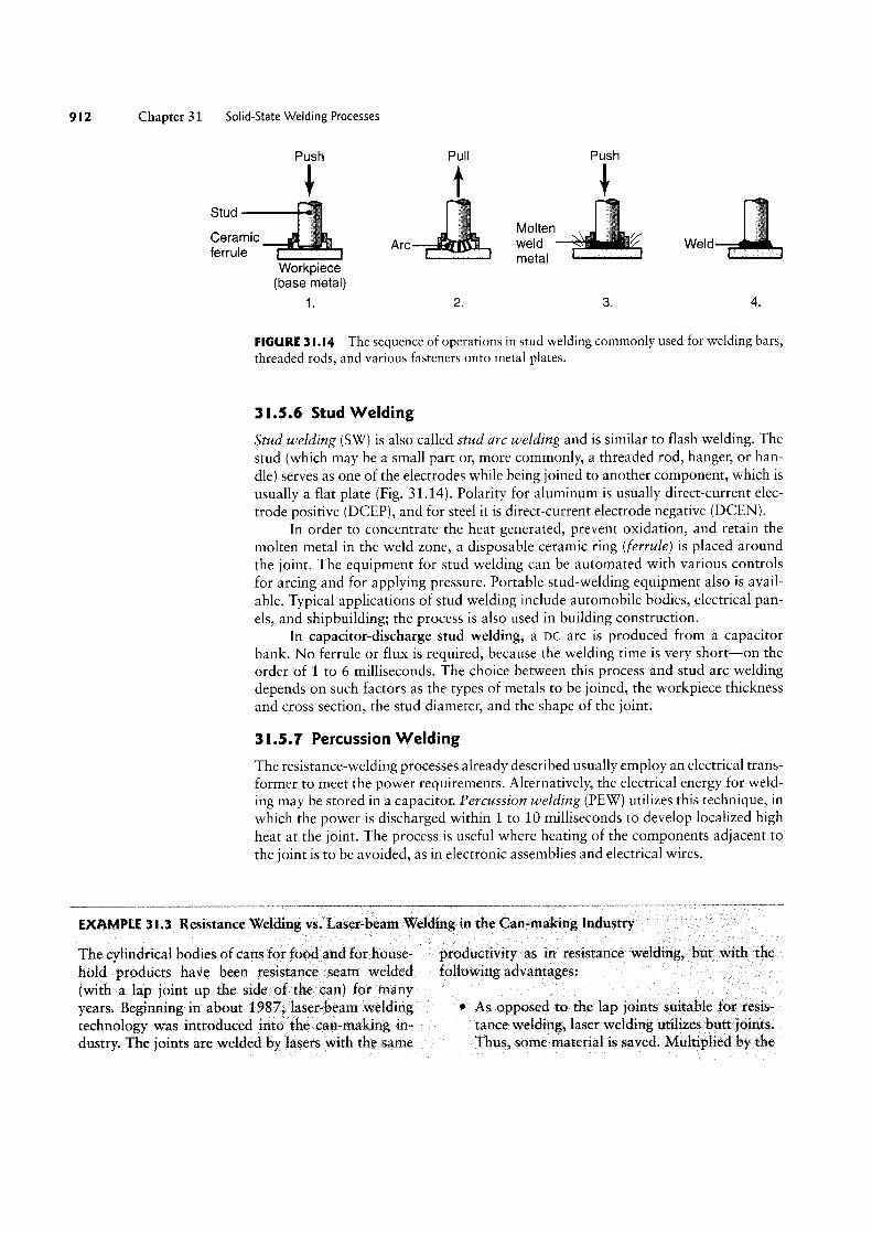
I2 Chapter 31 Solid-State Welding Processes
Push Pull Push
Stud 7, _ Molten
iéllflemc "Fl Arc f'? 'f|i\\f weld \ Weld Workpiece meta'
(base metal)
1 2. 3. 4.
FIGURE 3 l.l4 The sequence of operations in stud welding commonly used for welding bars,threaded rods, and various fasteners onto metal plates.
3 l.5.6 Stud Welding
Stud welding (SW) is also called stud are welding and is similar to flash welding. Thestud (which may be a small part or, more commonly, a threaded rod, hanger, or han-dle) serves as one of the electrodes while being joined to another component, which is
usually a flat plate (Fig. 31.14). Polarity for aluminum is usually direct-current elec-
trode positive (DCEP), and for steel it is direct-current electrode negative (DCEN).In order to concentrate the heat generated, prevent oxidation, and retain the
molten metal in the weld zone, a disposable ceramic ring (ferrule) is placed aroundthe joint. The equipment for stud welding can be automated with various controlsfor arcing and for applying pressure. Portable stud-welding equipment also is avail-able. Typical applications of stud welding include automobile bodies, electrical pan-els, and shipbuilding; the process is also used in building construction.
In capacitor-discharge stud welding, a DC arc is produced from a capacitorbank. No ferrule or flux is required, because the welding time is very short-on theorder of 1 to 6 milliseconds. The choice between this process and stud arc weldingdepends on such factors as the types of metals to be joined, the workpiece thicknessand cross section, the stud diameter, and the shape of the joint.
3I.5.1 Percussion Welding
The resistance-welding processes already described usually employ an electrical trans-former to meet the power requirements. Alternatively, the electrical energy for weld-ing may be stored in a capacitor. Percussion welding (PEW) utilizes this technique, in
which the power is discharged within 1 to 10 milliseconds to develop localized highheat at the joint. The process is useful where heating of the components adjacent tothe joint is to be avoided, as in electronic assemblies and electrical wires.
EXAMPLE 3 |.3 Resistance Welding vs. Laser-beam Welding in the Can-making Industry
The cylindrical bodies of cans for food and for house- productivity as in resistance welding, but with thehold products have been resistance seam welded following advantages:(with a lap joint up the side of the can) for manyyears. Beginning in about 1987, laser-beam welding ° As opposed to the lap joints suitable for resis-
technology was introduced into the can-making in- tance welding, laser welding utilizes butt joints.dustry. The joints are welded by lasers with the same Thus, some material is saved. Multiplied by the
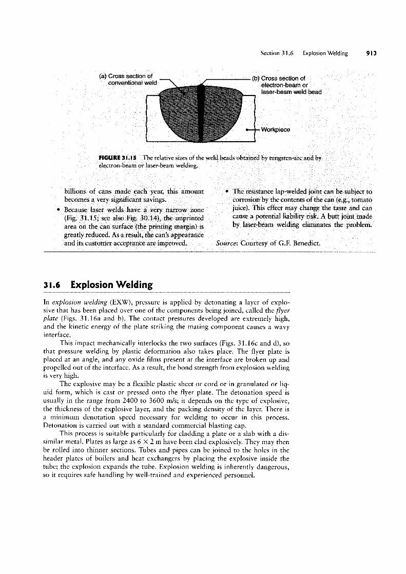
(a) Cross section of
Section 31.6 Explosion Welding 9| 3
(b) Cross section ofconventional weld electron-beam or
laser-beam weld bead
<plece
FIGURE 3|.|5 The relative sizes of the weld beads obtained by tungsten-arc and byelectron-beam or laser-beam welding.
billions of cans made each year; this amountbecomes a very significant savings.
Because laser vvelds have a very narrow zone(Fig. 31.15; see also Fig. 30.14), the unprintedarea on the can surface (the printing margin) is
greatly reduced. As a result, the can’s appearanceand its customer acceptance are improved.
The resistance lap-welded joint can be subject tocorrosion by the contents of the can (e.g., tomatojuice). This effect may change the taste and cancause a potential liability risk. A butt joint madeby laser-beam welding eliminates the problem.
Source: Courtesy of G.F. Benedict.
3 l.6 Explosion Welding
In explosion welding (EXW), pressure is applied by detonating a layer of explo-sive that has been placed over one of the components being joined, called the flyerplate (Figs. 31.16a and b). The contact pressures developed are extremely high,and the kinetic energy of the plate striking the mating component causes a wavyinterface.
This impact mechanically interlocks the two surfaces (Figs. 31.16c and d), sothat pressure welding by plastic deformation also takes place. The flyer plate is
placed at an angle, and any oxide films present at the interface are broken up andpropelled out of the interface. As a result, the bond strength from explosion weldingis very high.
The explosive may be a flexible plastic sheet or cord or in granulated or liq-uid form, which is cast or pressed onto the flyer plate. The detonation speed is
usually in the range from 2400 to 3600 mfs; it depends on the type of explosive,the thickness of the explosive layer, and the packing density of the layer. There is
a minimum denotation speed necessary for Welding to occur in this process.Detonation is carried out with a standard commercial blasting cap.
This process is suitable particularly for cladding a plate or a slab with a dis-similar metal. Plates as large as 6 X 2 m have been clad explosively. They may thenbe rolled into thinner sections. Tubes and pipes can be joined to the holes in theheader plates of boilers and heat exchangers by placing the explosive inside thetube; the explosion expands the tube. Explosion Welding is inherently dangerous,so it requires safe handling by well-trained and experienced personnel.

Chapter 31 Solid-State Welding Processes
Detonator Explosive Buffer
"Yer Clad metalDetonator Explosive Clad metal
( ) CO|'lStal`lt- AnQu|a|'-interface_ _ interface clearance gap
clearanceQHD- Base plate Base plate
(H) (D)
(C) (Ol)
FIGURE 3I.l6 Schematic illustration of the explosion-Welding process: (a) constant-interfaceclearance gap and (b) angular-interface clearance gap. (c) Cross section of explosion-weldedjoint: titanium (top) and low-carbon steel (bottom). (d) Iron-nickel alloy (top) and low-carbonsteel (bottom).
3 |.'! Diffusion Bonding
Diffusion bonding, or diffusion welding (DFW) is a process in which the strength of
the joint results primarily from diffusion (movement of atoms across the interface)and secondarily from plastic deformation of the faying surfaces. This process re-
quires temperatures of about O.5T,,, (Where Tm is the melting point of the metal onthe absolute scale) in order to have a sufficiently high diffusion rate between theparts being joined. (See also Sections 1.7 and 1.8.)
The bonded interface in diffusion welding has essentially the same physicaland mechanical properties as the base metal. Its strength depends on (a) pressure,(b) temperature, (c) time of contact, and (d) hovv clean the faying surfaces are. Theserequirements can be relaxed by using a filler metal at the interface. Depending on
the materials joined, brittle intermetallic compounds may form at the interface.They may be avoided by electroplating the surfaces with suitable metal alloys.
In diffusion bonding, pressure may be applied by dead weights, a press, differ-
ential gas pressure, or the thermal expansion of the parts to be joined. The partsusually are heated in a furnace or by electrical resistance. High-pressure autoclavesalso are used for bonding complex parts.
Although this process was developed in the 1970s as a modern Welding tech-nology, the principle of diffusion bonding dates back centuries to when goldsmithsbonded gold over copper to create a product called filled gold. First, a thin layer ofgold foil is produced and placed over copper, and a Weight is placed on top of thefoil. Finally, the assembly is placed in a furnace and left until a strong bond is
obtained; hence, the process is also called hot-pressure welding (HPW).
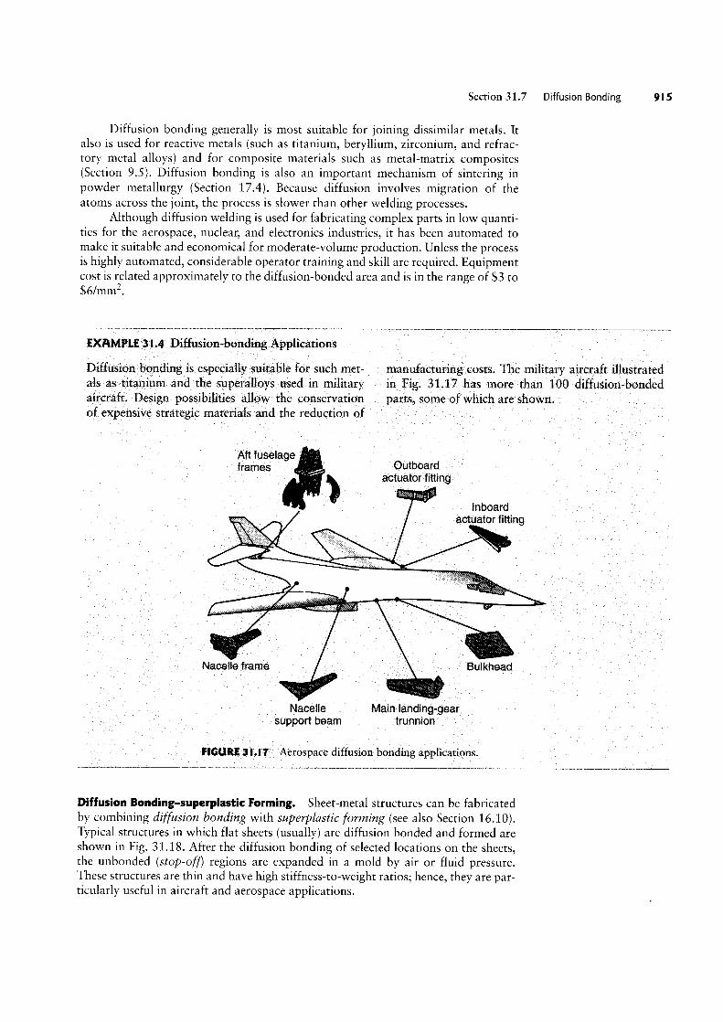
Section 31.7 Diffusion Bonding
Diffusion bonding generally is most suitable for joining dissimilar metals. Italso is used for reactive metals (such as titanium, beryllium, zirconium, and refrac-tory metal alloys) and for composite materials such as metal-matrix composites(Section 9.5). Diffusion bonding is also an important mechanism of sintering inpowder metallurgy (Section 17.4). Because diffusion involves migration of theatoms across the joint, the process is slower than other Welding processes.
Although diffusion welding is used for fabricating complex parts in low quanti-ties for the aerospace, nuclear, and electronics industries, it has been automated tomake it suitable and economical for moderate-volume production. Unless the processis highly automated, considerable operator training and skill are required. Equipmentcost is Belated approximately to the diffusion-bonded area and is in the range of $3 to$6/mm .
EXAMPLE 3 |.4 Diffusion-bonding Applications
Diffusion bonding is especially suitable for such met- manufacturing costs. The military aircraft illustratedals as titanium and the superalloys used in military in Fig. 31.17 has more than 100 diffusion bondedaircraft. Design possibilities allow the conservation parts, some of which are shownof expensive strategic materials and the reduction of
Aft fuselageffamgs Outboard
actuator fitting
inboardW actuator fitting
_i ,Z 1 ~ ffff' " " `A"' iii >
Nacel e frame Bulkhead
Naceile Main landing-gearsupport beam trunnion
FIGURE 3|.I 7 Aerospace diffusion bonding applications.
Diffusion Bonding-superplastic Forming. Sheet-metal structures can be fabricatedby combining diffusion bonding with superplczstic forming (see also Section 16.1O).Typical structures in which flat sheets (usually) are diffusion bonded and formed areshown in Fig. 31.18. After the diffusion bonding of selected locations on the sheets,the unbonded (stop-off) regions are expanded in a mold by air or fluid pressure.These structures are thin and have high stiffness-to-Weight ratios; hence, they are par-ticularly useful in aircraft and aerospace applications.
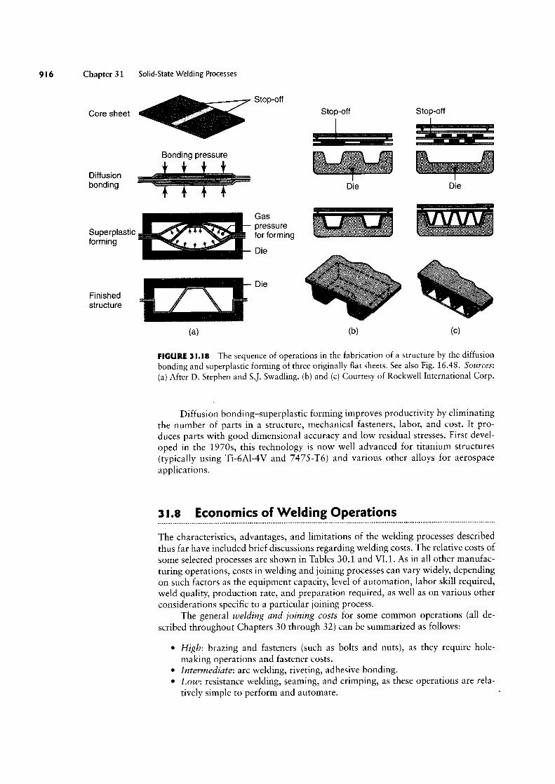
Chapter 31 Solid-State Welding Processes
Core sheet
Diffusionbonding
Superplasticforming
Finishedstructure
Stop-off
Stop-off Stop-off
Bonding pressure iiiiiT iiiiiiiii fiifi ifff" HH Die Die
Gas ,,»,_,,,_,f'<=
Die
(3) (U) (C)
FIGURE 3l.l8 The sequence of operations in the fabrication of a structure by the diffusionbonding and superplastic forming of three originally flat sheets. See also Fig. 16.48. Sources:
(a) After D. Stephen and S.]. Swadling. (b) and (C) Courtesy of Rockwell International Corp.
Diffusion bonding-superplastic forming improves productivity by eliminatingthe number of parts in a structure, mechanical fasteners, labor, and cost. It pro-duces parts With good dimensional accuracy and low residual stresses. First devel-
oped in the 1970s, this technology is now well advanced for titanium structures(typically using Ti-6Al-4V and 7475-T6) and various other alloys for aerospaceapplications.
3l.8 Economics of Welding Operations
The characteristics, advantages, and limitations of the welding processes describedthus far have included brief discussions regarding welding costs. The relative costs ofsome selected processes are shown in Tables 30.1 and Vl.1. As in all other manufac-turing operations, costs in Welding and joining processes can vary Widely, dependingon such factors as the equipment capacity, level of automation, labor skill required,weld quality, production rate, and preparation required, as vvell as on various otherconsiderations specific to a particular joining process.
The general welding and joining costs for some common operations (all de-
scribed throughout Chapters 30 through 32) can be summarized as follows:
° High: brazing and fasteners (such as bolts and nuts), as they require hole-making operations and fastener costs.
° Intermediate: arc Welding, riveting, adhesive bonding.° Low: resistance welding, seaming, and crimping, as these operations are rela-
tively simple to perform and automate.

Section 31.8 Economics of Welding Operations 9 I 7
Equipment costs for welding can be summarized as follows (note that thesecosts can vary widely):
° High ($100,000 to $200,000): electron-beam and laser-beam welding.° Intermediate ($5,000 to $50,000-i-): spot, submerged arc, gas metal-arc, gas
tungsten-arc, flux-cored arc, electrogas, electroslag, plasma arc, and ultrasonicwelding.
' Lou/ ($500+) shielded metal-arc and oxyfuel-gas welding.
Labor costs in welding generally are higher than in other metalworking opera-tions because of the operator skill, welding time, and preparation required. However,much depends on the automation of the equipment employed, including the use ofrobotics and computer controls programmed to follow a prescribed path (seam track-ing) during welding. It has been observed that in systems with robotic controls, thenumber reaches 80%, whereas in manual welding operations (see Table 30.1), theactual welding time spent by the operator is only about 30% of the overall time.
Lahor costs may be summarized as follows:
° High to intermediate: oxyfuel-gas welding and shielded metal-arc welding.° High to low: electron-beam and laser-beam welding and flux-cored arc welding.° Intermediate to lou/: submerged-arc welding.
CASE STUDY 3 l.I Friction Welding of Pistons
There has been a sustained effort among heavy-truckmanufacturers to design and manufacture diesel en-gines with reduced emissions. A number of technolo-gies have become more prevalent since the 1980s,reflecting the need for green design (see Sections L4and 40.4). Exhaust-gas recirculation (the reintroduc-tion of a portion of the spent exhaust gases into theintake stream of the engine) has become standardand is known to reduce nitrous-oxide emissions.Unfortunately, this strategy leads to less efficient com-bustion and lower component durability because ofthe abrasive-wear particles (see Section 33.5 ) andacids that are recirculated into the engine. To maintainand even improve engine efficiency, engine manufac-turers have increased cylinder pressures and operatingtemperatures, which together lead to an even more de-manding environment for engine components.
In the U.S. market, the traditional aluminumpistons in diesel engines were found to be unable tofunction reliably in modern engine designs. The prob-lems identified with pistons were a tendency to“mushroom” and fracture under the high firing pres-sures in the cylinder, inadequate cooling of the piston,and scuffing (wear) at the pin that joins the piston tothe connecting rod. A solution, shown in Fig. 31.19,is a Monosteel® piston, which has the following de-sign attributes:
' The piston is produced from steel, which hashigher strength and better high-temperature
mechanical properties than the aluminum alloyspreviously used (see Section 6.2).
' A two-piece design allows the incorporation ofan oil gallery, permitting circulation of coolingoil in the piston. One of the main advantages ofthe Monosteel® design is the use of a very largegallery, resulting in effective heat transfer fromthe piston. This design has been shown to reducepiston temperatures in the rim by around 40°Ccompared with earlier piston designs.
° The piston’s steel skirt is much more rigid thanthe aluminum skirt, resulting in smaller defor-mation and allowing for designs with tighterclearances. This feature results in‘a more stablepiston with less oil consumption (thus furtherreducing harmful exhaust emissions).
Monosteel® pistons are produced from twoforged components, which are machined prior towelding. The process used to join these componentsis inertia friction welding (Section 31.4), which hasthe following advantages in this application:
° The process leads to well-controlled, reliable,and repeatable high-quality welds.
° Friction welds are continuous and do not in-volve any porosity, thereby producing a high-strength weld that seals the oil gallery.
0 The welding process is fairly straightforwardto optimize, the main process variables being
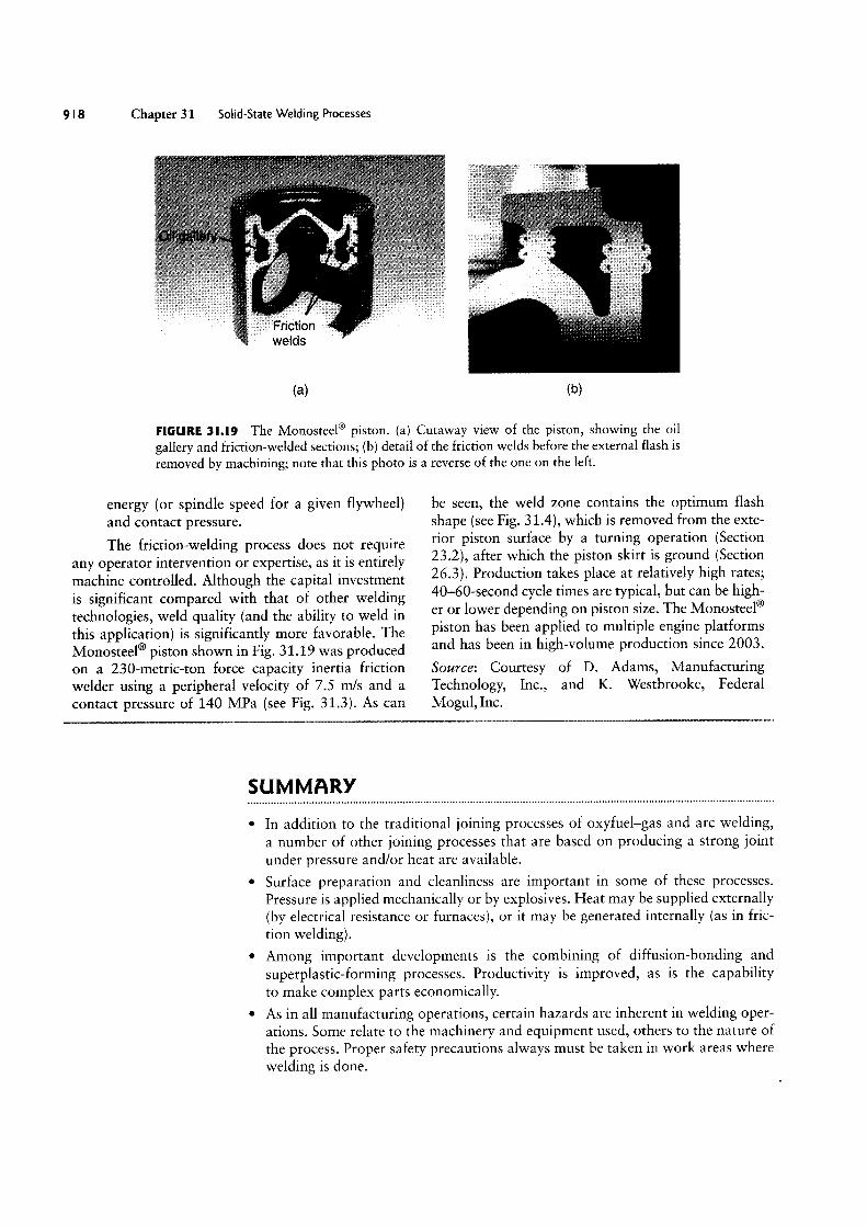
9 I 8 Chapter 31 Solid-State Welding Processes
welds
(H) (D)
FIGURE 3I.I9 The Monosteel® piston. (a) Cutaway view of the piston, showing the oil
gallery and friction-welded sections; (b) detail of the friction welds before the external flash is
removed by machining; note that this photo is a reverse of the one on the left.
energy (or spindle speed for a given flywheel)and Contact pressure.
The friction~welding process does not requireany operator intervention or expertise, as it is entirelymachine controlled. Although the capital investmentis significant compared with that of other weldingtechnologies, weld quality (and the ability to weld in
this application) is significantly more favorable. TheMonosteel® piston shown in Fig. 31.19 was producedon a 230-metric-ton force capacity inertia frictionwelder using a peripheral velocity of 7.5 mfs and a
contact pressure of 140 MPa (see Fig. 313). As can
be seen, the weld zone contains the optimum flashshape (see Fig. 31.4), which is removed from the exte-rior piston surface by a turning operation (Section232), after which the piston skirt is ground (Section263). Production takes place at relatively high rates;40-60-second cycle times are typical, but can be high-er or lower depending on piston size. The Monosteel®piston has been applied to multiple engine platformsand has been in high-volume production since 2003.
Source: Courtesy of D. Adams, ManufacturingTechnology, Inc., and K. Westbrooke, FederalMogul, Inc.
SUMMARY
° In addition to the traditional joining processes of oxyfuel-gas and arc weldinga number of other joining processes that are based on producing a strong jointunder pressure and/or heat are available.
° Surface preparation and cleanliness are important in some of these processesPressure is applied mechanically or by explosives. Heat may be supplied externally(by electrical resistance or furnaces), or it may be generated internally (as in friction welding).
° Among important developments is the combining of diffusion-bonding andsuperplastic-forming processes. Productivity is improved, as is the capabilityto make complex parts economically.
° As in all manufacturing operations, certain hazards are inherent in welding operations. Some relate to the machinery and equipment used, others to the nature ofthe process. Proper safety precautions always must be taken in work areas wherewelding is done.

KEY TERMS
Cold weldingDiffusion bonding
(welding)
Explosion weldingFaying surfacesFerruleFilled goldFlash weldingFlyer plate
Friction stir weldingFriction weldingHigh-frequency resistance
weldingInertia friction weldingLinear friction weldingPercussion weldingResistance projection
Welding
Resistance seamwelding
Resistance spotwelding
Resistance weldingRoll bondingRoll spot weldingRoll weldingSeam welding
Qualitative Problems
Solid-state weldingSonotrodeStud weldingSuperplastic formingTransducerUltrasonic weldingWeld nugget
BIBLIOGRAPHY
ASM Handbook, Vol. 6: Welding, Brazing, and Soldering,ASM International, 1993.
Bowditch, WA., and Bowditch, K.E., Welding TechnologyFundamentals, Goodheart-Willcox, 1997.
Cary, H.B., Modern Welding Technology, 6th ed., PrenticeHall, 2004.
Evans, G.M., and Bailey, N., Metallurgy of Basic WeldMetal, Woodhead Publishing, 1997.
Hicks, ].G., Welded Design: Theory and Practice, WilliamAndrews, 2005.
Houldcroft, T., Welding and Cutting: A Guide to FusionWelding and Associated Cutting Processes, IndustrialPress, 2001.
jeffus, L.F., Welding: Principles and Applications, 6th ed.,Delmar Publishers, 2007.
REVIEW QUESTIONS
3 l.|. Explain what is meant by solid-state welding.
3 |.2. What is cold welding? Why is it so called?
3I.3. What is (a) a ferrule, (b) filled gold, and (C) a flyerplate?
3|.4. What are faying surfaces in solid-state weldingprocesses?
3|.5. What is the basic principle of (a) ultrasonic weldingand (b) diffusion bonding?
Lagoda, T., Life Estimation of Welded joints, Springer, 2008.Mathers, G., Welding of Aluminum and its Alloys, CRC
Press, 2002.Mishra, R.S., and Mahoney, M.W, Friction Stir Welding and
Processing, American Society for Metals, 2007.Mouser, ].D., Welding Codes, Standards, and Specifications,
McGraw-Hill, 1997.Nicholas, M.G., ]oining Processes: Introduction to Brazing
and Diffusion Bonding, Chapman 86 Hall, 1998.Weman, K., Welding Process Handbook, CRC Press, 2003.Zhang, H., and Senkara, ]., Resistance Welding: Fundamentals
and Applications, CRC Press, 2005.
31.6. Describe the advantages and limitations of explosionwelding.
3 I.7. Describe the principle of resistance-welding processes.
31.8. What type of products are suitable for stud welding?Why?
3|.9. What is the advantage of linear friction Welding overinertia friction Welding?
3l.|0. Describe how high-frequency butt welding operates.
QUALITATIVE PROBLEMS
3l.l I. Explain the reasons that the processes described in
this chapter were developed.
3I.l2. Explain the similarities and differences between thejoining processes described in this chapter and those describedin Chapter 30.
3l.l3. Describe your observations concerning Fig. 31.16cand d.
3|.l4. Would you be concerned about the size of weldbeads, such as those shown in Fig. 31.15F Explain.
3 l.|5. What advantages does friction welding have overother methods described in this and in the preceding chapter?3 |.I6. Describe the significance of faying surfaces.3 l.l 7. Discuss the factors that influence the strength of (a) a
diffusion-bonded and (b) a cold-welded component.
920 Chapter 31 Solid-State Welding Processes
3l.I8. What are the sources of heat for the processes de-scribed in this chapter?
3l.|9. Can the roll-bonding process be applied to a varietyof part configurations? Explain.
3l.20. Why is diffusion bonding, when combined with thesuperplastic forming of sheet metals, an attractive fabricationprocess? Does it have any limitations?
3|.2l. List and explain the factors involved in the strengthof weld beads.
3|.22. Give some of the reasons that spot welding is usedcommonly in automotive bodies and in large appliances.
3 |.23. Explain the significance of the magnitude of the pres-sure applied through the electrodes during a spot-weldingoperation.
QUANTITATIVE PROBLEMS
3 I.24. Give some applications for (a) flash welding, (b) studwelding, and (c) percussion welding.
3I.25. Discuss the need for, and role of, work-holding de-vices in the welding operations described in this chapter.
3I.26. Inspect Fig. 31.4, and explain why those particularfusion-zone shapes are developed as a function of pressureand speed. Comment on the influence of the material’sproperties.
3I.27. Could the process shown in Fig. 31.11 also be appli-cable to part shapes other than round? Explain, and givespecific examples.
3l.28. In spot-weld tests, what would be the reason forweld failure to occur at the locations shown in Fig. 31.9?
3 I.29. The energy required in ultrasonic welding is found tobe related to the product of workpiece thickness and hard-ness. Explain why this relationship exists.
|]3I.30. Two flat copper sheets (each 1.0 mm thick) arebeing spot welded by the use of a current of 7000 A and a
current flow time of 0.3 s. The electrodes are 4 mm in diame-ter. Estimate the heat generated in the weld zone. Assume thatthe resistance is 200 /iQ.
SYNTHESIS, DESIGN, AND PROIECTS
|]3l.3|. Calculate the temperature rise in Problem 31.30,assuming that the heat generated is confined to the volume ofmaterial directly between the two round electrodes and thetemperature is distributed uniformly.
u3|.32. Calculate the range of allowable currents in
Problem 31.30 if the temperature should be between 0.7 and0.8 times the melting temperature of copper. Repeat thisproblem for carbon steel.
3 I.33. Comment on workpiece size and shape limitations (if
any) for each of the processes described in this chapter.
3 |.34. Explain how you would fabricate the structuresshown in Fig. 31.18 by methods other than diffusion bondingand superplastic forming.
3I.35. Describe part shapes that cannot be joined by theprocesses described in this chapter. Gives specific examples.
3|.36. Comment on the feasibility of applying explosionwelding in a factory environment.
3 I.37. Discuss your observations concerning the weldingdesign guidelines illustrated in Figs. 31.13d and e.
3|.38. Referring to Fig. 14.11b, could you use any of theprocesses described in Chapters 30 and 31 to make a largebolt by welding the head to the shank? Explain the advan-tages and limitations of this approach.
3l.39. Explain how the projection-welded parts shown in
Fig. 31.12 could be made by any of the processes described in
this book.
3 I.40. Using a magnifier, inspect the cross sections of coinssuch as the U.S. dime and nickel, and comment on yourobservations.
3|.4|. Describe the methods you would use for removingthe flash from welds, such as those shown in Fig. 31.3. Howwould you automate these methods for a high-productionfacility?
3l.42. In the roll-bonding process shown in Fig. 31.1, howwould you go about ensuring that the interfaces are clean andfree of contaminants so that a good bond is developed? Explain.
31.43. Inspect several metal containers for household prod-ucts and for food and beverages. Identify those which haveutilized any of the processes described in this chapter.Describe your observations.
3l.44. Inspect the sheet-metal body of an automobile, andcomment on the size and frequency of the spot welds applied.How would you go about estimating the number of welds in
an automobile?
3 |.45. Alclad stock is made from 5182 aluminum alloy andhas both sides coated with a thin layer of pure aluminum. The5182 provides high strength, while the outside layers of purealuminum provide good corrosion resistance because of theirstable oxide film. Hence, Alclad is commonly used in aerospacestructural applications. Investigate other common roll-bondedmetals and their uses, and write up a summary table.