k. sadecka, m. gajc, d. a. pawlak effect of the...
TRANSCRIPT

21
K. Sadecka, M. Gajc, D. A. Pawlak
The thermal residual stresses generated during the joining process are very important in the technology of ceramic-me-tal joints. The distribution and magnitude of these stresses mostly depend on the differences in the thermal and me-chanical properties of the components being joined, on the joining technique employed and also on the geometry of the joint. The knowledge of the effects exerted by each of these factors permits designing joints with the most advantageous distribution of stresses, so as to avoid or restrict their adverse effect on the operation of the system. In the present study, the residual stress state induced in a heat sink-laser diode system with various geometries of the heat-dissipating component was analyzed using the finite element method. The substrate was an aluminum nitride ceramic/copper joint. The variation of the stress level on a cross-section of the joint was examined and the stress concentration regions were determined. Based on the results obtained, the optimum configuration of the joint was found, such that ensured the maximum possible reduction of residual stresses.
Keywords: thermal residual stresse, heat-sink material, cera-mic-metal joints, composite.
1. INTRODUCTION
Dissipation of heat generated in electronic high--power components (e.g. diodes, thyristors, and lasers) during their operation has crucial significance for their effectiveness. The density of the heat flux evolved during the operation of e.g. semiconductor lasers may even amount to 10 kW/cm2 [1]. Favorable cooling conditions can be achieved by e.g. using materials of high thermal conductivity, and designing appropriately the heat-dissipating system. Usually, the heat dissipating system is made of ceramics and copper arranged in a multilayer configuration.
In most cases, ceramics and metals are joined at elevated temperatures using methods such as brazing or diffusion bonding. The great differences between
EFFECT OF THE SUBSTRATE GEOMETRY ON THE RESIDUAL STRESS STATE INDUCED IN A HEAT
SINK-LASER DIODE SYSTEM*)
Marcin Chmielewski1, Dariusz Kaliński1, Katarzyna Pietrzak1, Dariusz Golański2
1 Institute of Electronic Materials Technology, Composite Materials Laboratory, 01-919 Warszawa, ul. Wólczyńska 133, e-mail: [email protected]
2 Warsaw University of Technology, Faculty of Production Engineering, 02-524 Warszawa, ul. Narbutta 85
the thermal (linear expansion coefficients) and me-chanical (modulus of elasticity, plasticity) properties of these two materials results in residual stresses of high magnitude being generated during the cooling operation which follows the joining process [2 - 3]. These high residual stresses induced in the bonding region may lead to cracking (especially of the cera-mic element of the joint) or at least to degradation of the bonding strength of the joint.
The ceramic, which has low resistance to tensile stresses, is the component particularly liable to crac-king. The thermal expansion coefficients of ceramic materials are usually lower than those of metals, and thus tensile stresses of high magnitudes are locally induced in them during cooling. In view of the poor mechanical strength of ceramics (brittleness) these stresses may lead to cracking of the ceramic compo-nent and then to failure of the entire joint.
Various techniques of minimizing the magnitude of residual stresses are known, such as e.g. designing appropriately the shape of the components to be joined in the bonding zone [4], or introducing an interlayer between the ceramics and metal [5 - 6]. The materials commonly used for the interlayers can be divided into the four categories [7]:- plastic interlayer known as ‘soft’, made of highly
ductile materials (e.g. Cu) which, when deformed plastically, transmit the stresses,
- hard interlayer, made of metals or alloys whose thermal expansion coefficient α has an intermeo-diate value between those of the ceramic and the metal being joined (e.g. Mo, Nb, Kovar),
- ‘multiple’ interlayer (e.g. Cu/Kovar/ or Cu/Mo) which are a combination of the two interlayers described above, and
- interlayer made of functionally graded materials (FGM), in which the properties vary linearly wi-thin the material.
*) Praca prezentowana na 15th International Conference on Composite Structures ICCS 15, 15-17.06.2009, Porto, Portugalia.
M. Chmielewski, D. Kaliński, K. Pietrzak, D. Golański

Przegląd samoorganizujących się struktur eutektycznych...
22
The last type of interlayers offers especially gre-at possibilities of reducing the residual stress state thanks to the „fluent” change of the properties from one component of the joint to another [8 - 10].
The present study presents a numerical analysis of the thermal residual stress state induced in heat--sink/laser diode systems with various geometries of the heat-removing component.
2. ASSUMPTIONS AND OBJECT OF THE ANALYSIS
The distribution and magnitudes of the thermal residual stresses were analyzed using the LUSAS numerical program based on the finite element me-thod [11]. The object of the residual stress analysis was a heat-sink/laser diode system with various configurations of the heat-removing component. The models examined included:− Model I (Fig.1a) – the substrate is a direct joint
between the AlN ceramic and copper,− Model II (Fig.1b) – the substrate is a joint of AlN
ceramic with copper through a 50%AlN-50%Cu composite interlayer,
− Model III (Fig.1c) – the substrate is a gradient-ty-pe 6-layers ceramic-metal material with the follo-wing compositions of the individual layers: layer 1 – 100% of copper, layer 2 – 20% of AlN ceramic + 80% copper, layer 3 – 40% AlN ceramic + 60% copper, layer 4 – 60% AlN ceramic + 40% copper, layer 5 – 80% AlN ceramic + 20% copper, layer 6 – 100AlN ceramic (the name of graded material is used accordingly to other authors [8 - 9, 12]).
In each model, the thickness of the heat-sink was the same (1.8 mm), and the heat-sink was joined with the laser diode by soldering using the eutectic AgCu-28 solder whose melting temperature was 780°C.
The analysis was performed assuming a plane stress state. In view of the axial symmetry of the system with respect to the y axis, the model taken for the analysis was a half of the real laser/heat sink system. The finite element mesh was refined within the region of suspected stress concentration in the ceramic, i.e. near its outer surface and in the vicinity of the interface between the ceramic and metal.
The principal factor generating stresses within the joint is the variation of temperature. It is just the temperature fall from the maximum process temperature to room temperature which, together with the difference between the properties (Δα, ΔE) of the materials being joined, generates residual stresses in the joint. The loading conditions of the model are defined by the course of the processes of joining the ceramic with metal, and bonding the joint thus produced with the laser diode. Hence, the temperature cycle includes:− stage I – cooling from the joining temperature
of 1050oC to room temperature (20oC), which completes the process of fabrication of the cera-mic/metal joint,
− stage II - heating the substrate/laser arrangement from room temperature (20oC) to the brazing tem-perature (780oC),
− stage III – cooling from the brazing temperature (780oC) to room temperature (20oC) which gives a durable bond between the heat-sink and the laser diode.
(a) (b) (c)
Fig. 1. Models designed for the analysis of residual stresses induced in laser/substrate systems.Rys. 1. Modele do analizy naprężeń własnych w układach laser-podłoże.
The properties of the materials useful for FEM analysis [14], described by the linear thermal ex-pansion coefficient α, Young modulus E, yield point Re, and the Poisson ratio ν, are given in Tab 1. Except the Poisson ratio which was assumed to be temperature independent, the remaining parameters
vary with temperature. The Young moduli, thermal expansion coefficients and Poisson ratios of the AlN-Cu composites were estimated based on the rule of mixtures, with the use of the Voigt model [7]. The yield point Re of the composites in which the content of the reinforcing phase is below 50%
Effect of the substrate geometry on the residual stress state induced...
23
K. Sadecka, M. Gajc, D. A. Pawlak
was taken to be the same as that of copper. Above this value, the composites were assumed to undergo
elastic deformation alone, just as is the case in pure ceramic materials [12].
Table 1. Properties of the materials (at room temperature) assumed in the numerical analysis of the residual stress state.Tabela 1. Właściwości materiałów (w temperaturze otoczenia) przyjęte do obliczeń numerycznych stanu naprężeń własnych.
Material Thermal expansion coeffi-cient (10-6 1/K)
Young modulus(GPa)
Yield point (MPa) Poisson’s ratio
Cu 16.8 131.0 49.0 0.36AlN 4.8 310.0 - 0.24
GaAs 5.4 85.5 - 0.32AgCu28 17.4 58.0 35.0 0.34
The aim of performed analyses was checking of the possibility of the obtaining the heat sink – laser diode joints with the respect to thermal stresses generated during the joining process. The criterion assumed for the analysis was that level of tensile stresses in ceramic part of analyzed models should not exceed the bending strength of ceramics.
3. RESULTS AND DISCUSSION
In ceramic/metal joints, the region most subject to failure due to residual stresses is that near the
ceramic/metal bonding surface, close to the outer edge of the components being joined where the stress concentration is the highest. Ceramic materials have a high compressive strength, but they are brittle and their tensile strength is relatively low. The bending strength of AlN ceramics is about 300 MPa and, thus, the maximum tensile stress assumed to be admitted in the ceramic component of the joint must not exceed this value.
The numerical analysis gave maps of the distribu-tion of the thermal residual stresses and their magnitu-des at the gravity centers of the joint components. The computer program employed permitted determining the following components of the stress state:
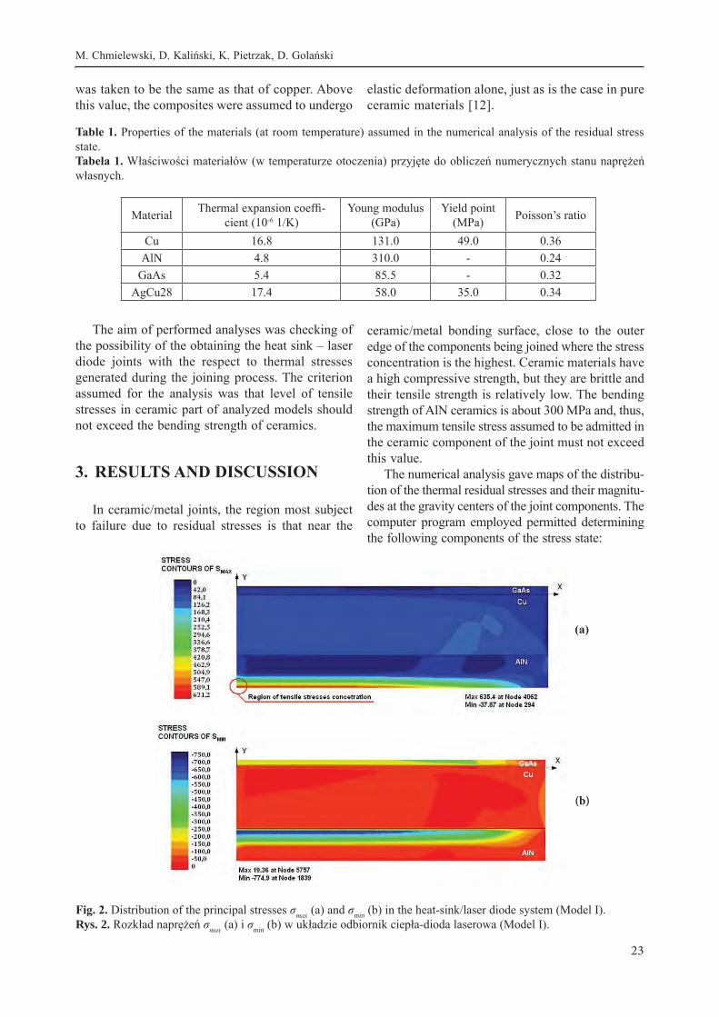
Fig. 2. Distribution of the principal stresses σmax (a) and σmin (b) in the heat-sink/laser diode system (Model I).Rys. 2. Rozkład naprężeń σmax (a) i σmin (b) w układzie odbiornik ciepła-dioda laserowa (Model I).
(a)
(b)
M. Chmielewski, D. Kaliński, K. Pietrzak, D. Golański
Przegląd samoorganizujących się struktur eutektycznych...
24
− σmax and σmin - the maximum and minimum prin-cipal stresses – active in the principal axis, where exist only normal stresses (perpendicular to the surface), and shear stresses equal 0,
− σx and σy - axial stress – active in x and y axis, respectively (x and y direction result from the assumed geometry of the models),
− τxy - shear stress – active in tangential direction to the surface [11,14]. Fig. 2 shows the maps of the distribution of the
principal stresses (σmax and σmin) on a cross-section of the heat-sink/laser diode system represented by Model I.
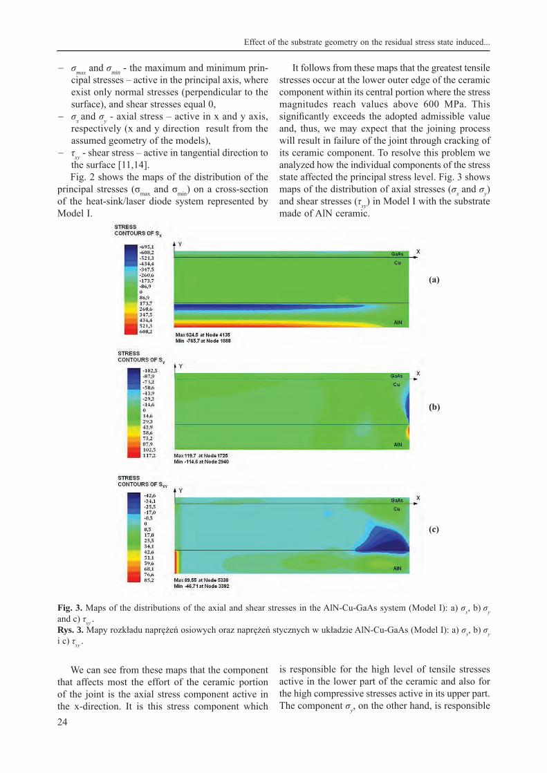
It follows from these maps that the greatest tensile stresses occur at the lower outer edge of the ceramic component within its central portion where the stress magnitudes reach values above 600 MPa. This significantly exceeds the adopted admissible value and, thus, we may expect that the joining process will result in failure of the joint through cracking of its ceramic component. To resolve this problem we analyzed how the individual components of the stress state affected the principal stress level. Fig. 3 shows maps of the distribution of axial stresses (σx and σy) and shear stresses (τxy) in Model I with the substrate made of AlN ceramic.
(a)
(b)
(c)
Fig. 3. Maps of the distributions of the axial and shear stresses in the AlN-Cu-GaAs system (Model I): a) σx, b) σy and c) τxy .Rys. 3. Mapy rozkładu naprężeń osiowych oraz naprężeń stycznych w układzie AlN-Cu-GaAs (Model I): a) σx, b) σy i c) τxy .
We can see from these maps that the component that affects most the effort of the ceramic portion of the joint is the axial stress component active in the x-direction. It is this stress component which
is responsible for the high level of tensile stresses active in the lower part of the ceramic and also for the high compressive stresses active in its upper part. The component σy, on the other hand, is responsible
Effect of the substrate geometry on the residual stress state induced...

25
K. Sadecka, M. Gajc, D. A. Pawlak
for the increased stress level at the side edge of the ceramic, immediately at the ceramic-copper bond-ing surface.
From the point of view of the operation of the laser, it is crucially important that the stress level in the semiconductor should be as low as possible. The numerical analysis performed for the AlN-Cu-GaAs system (Model I) has shown that the magnitude of the principal stresses ranges from about -300 MPa to near 100 MPa. The component deciding about the principal stress level appears to be the axial component σx. This relatively high stress level may affect the operation of the laser. It should however be noticed that, in the case of real heat-sink/laser diode systems, the joining process is conducted with low-
melting brazes such as indium (melting temperature – 156oC) or the PbSn40 braze (melting temperature – 177oC). Thanks to this low joining temperature, whose consequence is that the joint is cooled from a lower temperature, together with the high plasticity of the brazes employed, the real residual stress level in the joints is lower.
In Model II, the heat-sink was a ceramic-copper joint with a composite interlayer. The reduced dif-ferences in the thermal and mechanical properties of the components of this system with respect to those used in Model I should ensure that the residual stress level will be lower and the stress distribution more fluent. Fig. 4 shows maps of the distributions of the principal stresses σMAX and σMIN in Model II.
(a)
(b)
Fig. 4. Distribution of the principal stresses σmax (a) and σmin (b) in the heat-sink/laser diode system (Model II).Rys. 4. Rozkład naprężeń głównych σmax (a) i σmin (b) w układzie odbiornik ciepła – dioda laserowa (Model II).
The results obtained with Model II indicate that the residual stress level on a cross-section of the en-tire joint is lower than that in Model I. In the ceramic component of the joint we have two regions with a high level of tensile stresses. Just as in Model I, high principal stresses σMAX occur here in the bottom part of the ceramic component but they are smaller by 10% (decrease from 635 MPa to 568 MPa).
Another region with a high level of tensile stresses is that at the side edge of the ceramic near the surface of its bonding with the 50%AlN/50%Cu composite layer. The maximum magnitude of the tensile stresses in this region amounts to 142 MPa.
The central part of the ceramic, near the surface of its bonding with the composite inter-layer is acted upon by high compressive stresses which do not however affect the strength of the ceramic. The individual stress components are similar in character to those active in Model I. We must however admit that the magnitude of the principal stresses σMAX induced in the ceramic component of the joint exceeds its bending strength, which may lead to its cracking and failure of the joint.
In view of these unsatisfactory results, we con-structed Model III where the substrate was a graded material composed of 6 consecutive layers. The first
M. Chmielewski, D. Kaliński, K. Pietrzak, D. Golański

Przegląd samoorganizujących się struktur eutektycznych...
26
layer was ceramic, next four layers were built of AlN-Cu composite, and the last layer, joined with the laser diode, was copper. Fig. 5 shows maps of the distributions of the principal stresses σmax and σmin in Model III of the heat-sink/laser diode system.
It follows from these maps that the region where the tensile stresses are the highest is the AlN60-Cu40 layer, whereas the highest compressive stresses are active in the semiconductor component. In these re-gions, the highest magnitudes of the principal stresses
(a)
(b)
Fig. 5. Distributions of the principal stresses σmax (a) and σmin (b) in the AlN-FGM-Cu-GaAs system (Model III).Rys. 5. Rozkład naprężeń głównych σmax (a) i σmin (b) w układzie AlN-FGM-Cu-GaAs (Model III).
amount to σmin = 271 MPa and σmin = -467 MPa, re-spectively. It should however be noted that, within the ceramic component, the stress magnitude does not exceed the bending strength of the ceramic. In view of our assumption that, if the joining opera-tion is to be satisfactory (as far as thermal residual stresses induced in the joint are concerned), this con-dition must be fulfilled, Model III should be accepted as the most advantageous model. Fig. 6 shows the distributions of the principal stresses (σmax, σmin) on 2 cross-sections of the FGM substrate-GaAs system.
(a)
(b)
Fig. 6. Linear distributions of the principal stresses σmax, and σmin in the AlN-FGM-Cu-GaAs system (Model III): (a) x = 5.6 mm, and (b) x = 6.0 mm.Rys. 6. Liniowe rozkłady naprężeń głównych σmax i σmin dla Modelu III w układzie AlN-FGM-Cu-GaAs: a) dla x=5,6mm, b) dla x=6,0mm.
We can see that, in Model III, the stress distri-bution on a cross-section through the entire joint is uniform and the stress level is low. It is worth noting that the tensile residual stresses induced in the ceramic component of the joint do not exceed
Effect of the substrate geometry on the residual stress state induced...
27
K. Sadecka, M. Gajc, D. A. Pawlak
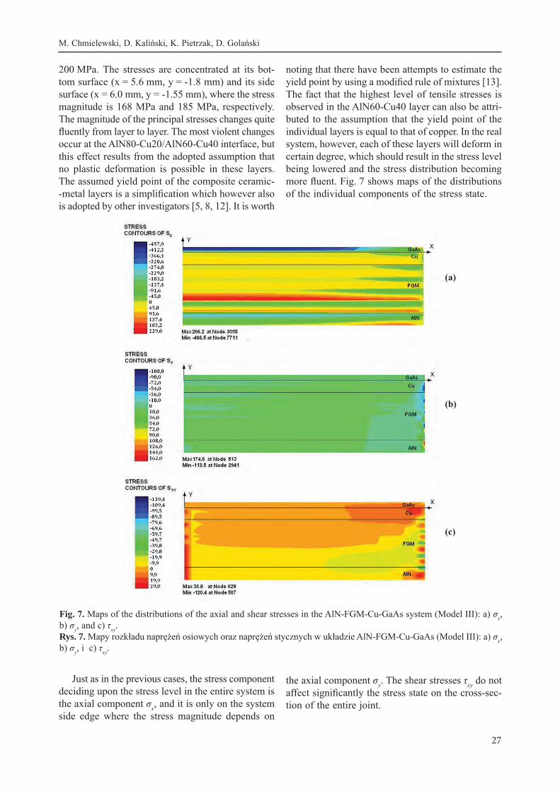
200 MPa. The stresses are concentrated at its bot-tom surface (x = 5.6 mm, y = -1.8 mm) and its side surface (x = 6.0 mm, y = -1.55 mm), where the stress magnitude is 168 MPa and 185 MPa, respectively. The magnitude of the principal stresses changes quite fluently from layer to layer. The most violent changes occur at the AlN80-Cu20/AlN60-Cu40 interface, but this effect results from the adopted assumption that no plastic deformation is possible in these layers. The assumed yield point of the composite ceramic--metal layers is a simplification which however also is adopted by other investigators [5, 8, 12]. It is worth
noting that there have been attempts to estimate the yield point by using a modified rule of mixtures [13]. The fact that the highest level of tensile stresses is observed in the AlN60-Cu40 layer can also be attri-buted to the assumption that the yield point of the individual layers is equal to that of copper. In the real system, however, each of these layers will deform in certain degree, which should result in the stress level being lowered and the stress distribution becoming more fluent. Fig. 7 shows maps of the distributions of the individual components of the stress state.
(c)
(a)
(b)
Fig. 7. Maps of the distributions of the axial and shear stresses in the AlN-FGM-Cu-GaAs system (Model III): a) σx, b) σy, and c) τxy.Rys. 7. Mapy rozkładu naprężeń osiowych oraz naprężeń stycznych w układzie AlN-FGM-Cu-GaAs (Model III): a) σx, b) σy, i c) τxy.
Just as in the previous cases, the stress component deciding upon the stress level in the entire system is the axial component σx, and it is only on the system side edge where the stress magnitude depends on
the axial component σy. The shear stresses τxy do not affect significantly the stress state on the cross-sec-tion of the entire joint.
M. Chmielewski, D. Kaliński, K. Pietrzak, D. Golański

Przegląd samoorganizujących się struktur eutektycznych...
28
4. SUMMARY AND CONCLUSIONS
The aim of the analysis performed in the present study was to find how the structure of the material used for the substrate in heat-sink/laser diode sys-tems affects the thermal residual stress state induced
in them, with special attention paid to the tensile stresses induced in the ceramic component of the joint, and to the magnitudes of the principal stresses σmax and σmin. Tab. 2 gives the extreme values of the principal stresses σmax determined in the ceramic substrate and in the entire Model.
Lower edge of the ceramic component
Side edge of the ceramic com-ponent Entire system
σMAX1 σMAX2 σMAX3 σMAX1 σMAX2 σMAX3 σMAX1 σMAX2 σMAX3
635 MPa
187 MPa
168 MPa
120 MPa
400 MPa
185 MPa
635 MPa
433 MPa
271MPa
Table 2. Extreme magnitudes of the stress σmax occurring in heat-sink/laser diode systems (σmax1 – Model I, σmax2 – Model II, σmax3 – Model III).Tabela 2. Ekstremalne wartości naprężeń σmax w analizowanych układach połączeń odbiornik ciepła – dioda laserowa (σmax1 – Model I, σmax2 – Model II, σmax3 – Model III).
It has been found that in Model I (direct bond between the AlN ceramic and metal) and Model II (a composite interlayer between the AlN ceramic and metal), the level of the residual stresses induced in the ceramic considerably exceeds its bending strength. The region with maximum tensile stresses is the lower edge of the ceramic in its central part. The magnitude of the principal stresses in the bottom re-gion of the ceramic depends most on the axial stress component σx. This is associated with the geometry of the analyzed models, since the bending moments with respect to the y-axis result in the bottom part of the ceramic component being stretched and the upper part of the semiconductor component being compressed. The stress component σy is responsible for the stress concentration near the bonding surface between the ceramic and the layer adjacent to it. The difference in the thermal expansion coefficients between these layers results in stretching of the ce-ramic. In both cases, the level of the residual stresses active in the copper component was low which was due to the ability of copper to deform plastically. In the semiconductor component, on the other hand, we have high compressive stresses which could degrade considerably the effectiveness of the operation of the laser diode. As mentioned earlier, this is a result of the assumed type of braze which is not however used in practice. This purely theoretical assumption was adopted in order to visualize better the residual stress state that prevails in the heat dissipating sub-strate. Brazes used in practice (e.g. indium) have a ow melting temperature and thus such high brazing temperatures are not needed.
In Model III, the substrate was made of ceramic joined with metal through an FGM composed of four layers in which the ceramic – to-copper content ratio changed in a step-wise manner from layer to layer. This configuration gave a relatively „fluent” transition from the properties of one layer to those of another.
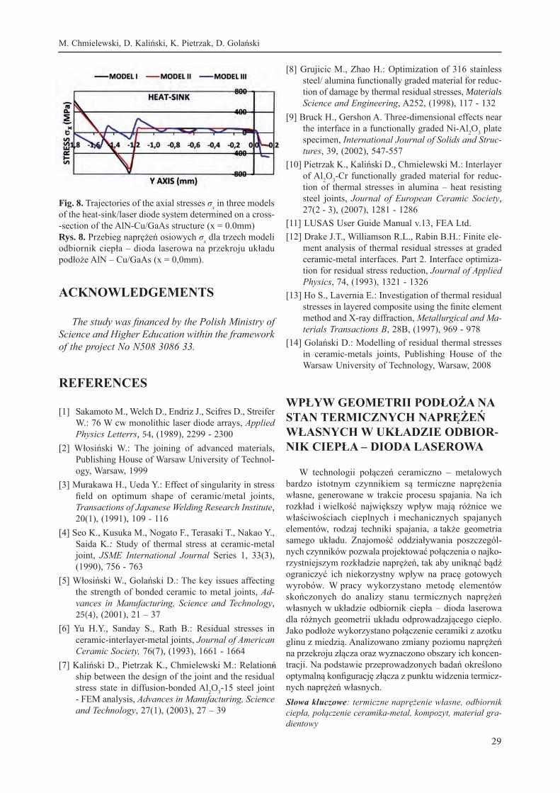
This configuration appears to be decidedly the most advantageous. As can be seen, the magnitude of the principal stresses σmax does not exceed the bend-ing strength of the ceramic. The region most subject to the action of tensile stresses is the lower edge of the ceramic, at a small distance from its side edge (x = 5.6 mm, y = -1.8 mm), and its side edge near the bonding surface (x = 6.0 mm, y = -1.5 mm). From the point of view of the adopted criterion taken to define the condition necessary to produce a durable bond, Model III can be considered to be the most advanta-geous configuration. Fig. 8 compares the variation of the axial stress σx active in the three models of a heat sink/laser diode system along the y-coordinate, tak-ing aluminum nitride ceramic as an example.
From the point of view of the magnitude and distribution of residual stresses in the proposed mo-dels of the heat-sink/laser diode systems, the most advantageous substrate appears to be that made of ceramic bonded with copper through a 4-layer graded AlN-Cu-based material (Model III). In this configuration the residual stress level in the ceramic component of the joint was the lowest. Moreover, the use of FGM based on an AlN-Cu composite is addi-tionally advantageous because of the good thermal conductivity of these materials, a property which has crucial significance for heat-dissipating materials.
Effect of the substrate geometry on the residual stress state induced...
29
K. Sadecka, M. Gajc, D. A. Pawlak
Fig. 8. Trajectories of the axial stresses σx in three models of the heat-sink/laser diode system determined on a cross--section of the AlN-Cu/GaAs structure (x = 0.0mm)Rys. 8. Przebieg naprężeń osiowych σx dla trzech modeli odbiornik ciepła – dioda laserowa na przekroju układu podłoże AlN – Cu/GaAs (x = 0,0mm).
ACKNOWLEDGEMENTS
The study was financed by the Polish Ministry of Science and Higher Education within the framework of the project No N508 3086 33.
REFERENCES
[1] Sakamoto M., Welch D., Endriz J., Scifres D., Streifer W.: 76 W cw monolithic laser diode arrays, Applied Physics Letterrs, 54, (1989), 2299 - 2300
[2] Włosiński W.: The joining of advanced materials, Publishing House of Warsaw University of Technol-ogy, Warsaw, 1999
[3] Murakawa H., Ueda Y.: Effect of singularity in stress field on optimum shape of ceramic/metal joints, Transactions of Japanese Welding Research Institute, 20(1), (1991), 109 - 116
[4] Seo K., Kusuka M., Nogato F., Terasaki T., Nakao Y., Saida K.: Study of thermal stress at ceramic-metal joint, JSME International Journal Series 1, 33(3), (1990), 756 - 763
[5] Włosiński W., Golański D.: The key issues affecting the strength of bonded ceramic to metal joints, Ad-vances in Manufacturing, Science and Technology, 25(4), (2001), 21 – 37
[6] Yu H.Y., Sanday S., Rath B.: Residual stresses in ceramic-interlayer-metal joints, Journal of American Ceramic Society, 76(7), (1993), 1661 - 1664
[7] Kaliński D., Pietrzak K., Chmielewski M.: Relationń-ship between the design of the joint and the residual stress state in diffusion-bonded Al 2O3-15 steel joint - FEM analysis, Advances in Manufacturing, Science and Technology, 27(1), (2003), 27 – 39
[8] Grujicic M., Zhao H.: Optimization of 316 stainless steel/ alumina functionally graded material for reduc-tion of damage by thermal residual stresses, Materials Science and Engineering, A252, (1998), 117 - 132
[9] Bruck H., Gershon A. Three-dimensional effects near the interface in a functionally graded Ni-Al2O3 plate specimen, International Journal of Solids and Struc-tures, 39, (2002), 547-557
[10] Pietrzak K., Kaliński D., Chmielewski M.: Interlayer of Al2O3-Cr functionally graded material for reduc-tion of thermal stresses in alumina – heat resisting steel joints, Journal of European Ceramic Society, 27(2 - 3), (2007), 1281 - 1286
[11] LUSAS User Guide Manual v.13, FEA Ltd.[12] Drake J.T., Williamson R.L., Rabin B.H.: Finite ele-
ment analysis of thermal residual stresses at graded ceramic-metal interfaces. Part 2. Interface optimiza-tion for residual stress reduction, Journal of Applied Physics, 74, (1993), 1321 - 1326
[13] Ho S., Lavernia E.: Investigation of thermal residual stresses in layered composite using the finite element method and X-ray diffraction, Metallurgical and Ma-terials Transactions B, 28B, (1997), 969 - 978
[14] Golański D.: Modelling of residual thermal stresses in ceramic-metals joints, Publishing House of the Warsaw University of Technology, Warsaw, 2008
WPŁYW GEOMETRII PODŁOŻA NA STAN TERMICZNYCH NAPRĘŻEŃ WŁASNYCH W UKŁADZIE ODBIOR-NIK CIEPŁA – DIODA LASEROWA
W technologii połączeń ceramiczno – metalowych bardzo istotnym czynnikiem są termiczne naprężenia własne, generowane w trakcie procesu spajania. Na ich rozkład i wielkość największy wpływ mają różnice we właściwościach cieplnych i mechanicznych spajanych elementów, rodzaj techniki spajania, a także geometria samego układu. Znajomość oddziaływania poszczegól-nych czynników pozwala projektować połączenia o najko-rzystniejszym rozkładzie naprężeń, tak aby uniknąć bądź ograniczyć ich niekorzystny wpływ na pracę gotowych wyrobów. W pracy wykorzystano metodę elementów skończonych do analizy stanu termicznych naprężeń własnych w układzie odbiornik ciepła – dioda laserowa dla różnych geometrii układu odprowadzającego ciepło. Jako podłoże wykorzystano połączenie ceramiki z azotku glinu z miedzią. Analizowano zmiany poziomu naprężeń na przekroju złącza oraz wyznaczono obszary ich koncen-tracji. Na podstawie przeprowadzonych badań określono optymalną konfigurację złącza z punktu widzenia termicz-nych naprężeń własnych.Słowa kluczowe: termiczne naprężenie własne, odbiornik ciepła, połączenie ceramika-metal, kompozyt, materiał gra-dientowy
M. Chmielewski, D. Kaliński, K. Pietrzak, D. Golański