jumper cable connection feeder cable to 2 prepare the ...€¢ when wrapping tape, ......
TRANSCRIPT
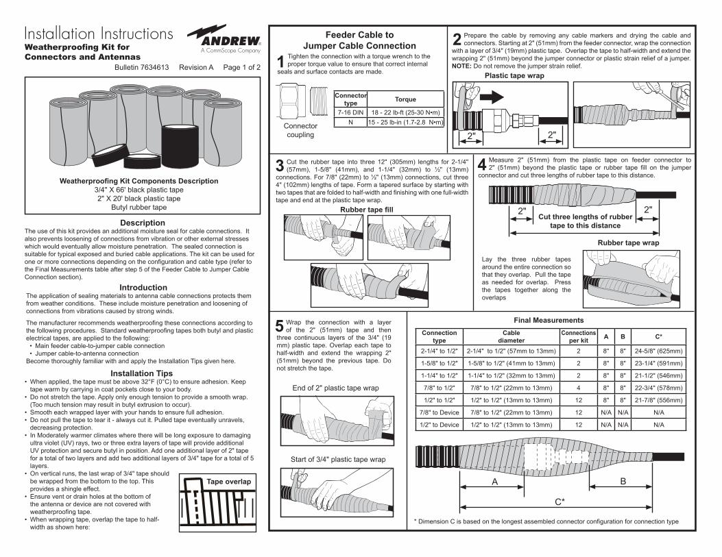
Cut the rubber tape into three 12" (305mm) lengths for 2-1/4" (57mm), 1-5/8" (41mm), and 1-1/4" (32mm) to ½" (13mm)
connections. For 7/8" (22mm) to ½" (13mm) connections, cut three 4" (102mm) lengths of tape. Form a tapered surface by starting with two tapes that are folded to half-width and finishing with one full-width tape and end at the plastic tape wrap.
Bulletin 7634613 Revision A Page 1 of 2
Measure 2" (51mm) from the plastic tape on feeder connector to 2" (51mm) beyond the plastic tape or rubber tape fill on the jumper
connector and cut three lengths of rubber tape to this distance.
Lay the three rubber tapes around the entire connection so that they overlap. Pull the tape as needed for overlap. Press the tapes together along the overlaps
Feeder Cable to Jumper Cable Connection
Connector coupling
Plastic tape wrap
Rubber tape fill
Rubber tape wrap
Cut three lengths of rubber tape to this distance
Final Measurements
Connectortype Torque
7-16 DIN 18 - 22 lb-ft (25-30 N•m)N 15 - 25 lb-in (1.7-2.8 N•m)
Tighten the connection with a torque wrench to the proper torque value to ensure that correct internal
seals and surface contacts are made.
Prepare the cable by removing any cable markers and drying the cable and connectors. Starting at 2" (51mm) from the feeder connector, wrap the connection
with a layer of 3/4" (19mm) plastic tape. Overlap the tape to half-width and extend the wrapping 2" (51mm) beyond the jumper connector or plastic strain relief of a jumper. NOTE: Do not remove the jumper strain relief.
Wrap the connection with a layer of the 2" (51mm) tape and then
three continuous layers of the 3/4" (19 mm) plastic tape. Overlap each tape to half-width and extend the wrapping 2" (51mm) beyond the previous tape. Do not stretch the tape.
End of 2" plastic tape wrap
Start of 3/4" plastic tape wrap
IntroductionThe application of sealing materials to antenna cable connections protects them from weather conditions. These include moisture penetration and loosening of connections from vibrations caused by strong winds.
The manufacturer recommends weatherproofing these connections according to the following procedures. Standard weatherproofing tapes both butyl and plastic electrical tapes, are applied to the following:
• Main feeder cable-to-jumper cable connection• Jumper cable-to-antenna connection
Become thoroughly familiar with and apply the Installation Tips given here.
Installation Tips• When applied, the tape must be above 32°F (0°C) to ensure adhesion. Keep
tape warm by carrying in coat pockets close to your body.• Do not stretch the tape. Apply only enough tension to provide a smooth wrap.
(Too much tension may result in butyl extrusion to occur).• Smooth each wrapped layer with your hands to ensure full adhesion.• Do not pull the tape to tear it - always cut it. Pulled tape eventually unravels,
decreasing protection.• In Moderately warmer climates where there will be long exposure to damaging
ultra violet (UV) rays, two or three extra layers of tape will provide additional UV protection and secure butyl in position. Add one additional layer of 2" tape for a total of two layers and add two additional layers of 3/4" tape for a total of 5 layers.
• On vertical runs, the last wrap of 3/4" tape should be wrapped from the bottom to the top. This provides a shingle effect.
• Ensure vent or drain holes at the bottom of the antenna or device are not covered with weatherproofing tape.
• When wrapping tape, overlap the tape to half-width as shown here:
DescriptionThe use of this kit provides an additional moisture seal for cable connections. It also prevents loosening of connections from vibration or other external stresses which would eventually allow moisture penetration. The sealed connection is suitable for typical exposed and buried cable applications. The kit can be used for one or more connections depending on the configuration and cable type (refer to the Final Measurements table after step 5 of the Feeder Cable to Jumper Cable Connection section).
* Dimension C is based on the longest assembled connector configuration for connection type
Connection type
Cable diameter
Connections per kit A B C*
2-1/4" to 1/2" 2-1/4" to 1/2" (57mm to 13mm) 2 8" 8" 24-5/8" (625mm)
1-5/8" to 1/2" 1-5/8" to 1/2" (41mm to 13mm) 2 8" 8" 23-1/4" (591mm)
1-1/4" to 1/2" 1-1/4" to 1/2" (32mm to 13mm) 2 8" 8" 21-1/2" (546mm)
7/8" to 1/2" 7/8" to 1/2" (22mm to 13mm) 4 8" 8" 22-3/4" (578mm)
1/2" to 1/2" 1/2" to 1/2" (13mm to 13mm) 12 8" 8" 21-7/8" (556mm)
7/8" to Device 7/8" to 1/2" (22mm to 13mm) 12 N/A N/A N/A
1/2" to Device 1/2" to 1/2" (13mm to 13mm) 12 N/A N/A N/A
Weatherproofing Kit for Connectors and Antennas 1
2
3
5
4Weatherproofing Kit Components Description
3/4" X 66' black plastic tape 2" X 20' black plastic tape
Butyl rubber tape
2"
2" 2"
2"
Tape overlap A
C*
B
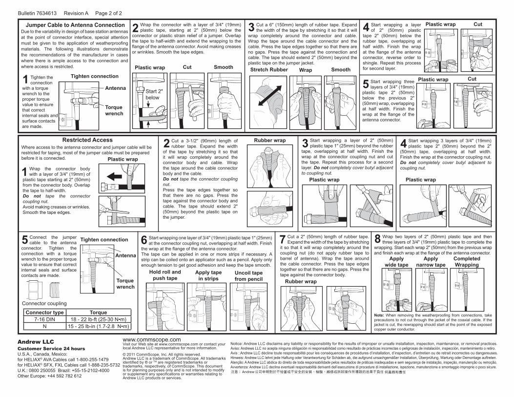
Start wrapping a layer of 2" (50mm) plastic
tape 2" (50mm) below the rubber tape, overlapping at half width. Finish the wrap at the flange of the antenna connector, reverse order to shingle. Repeat this process for second layer.
Where access to the antenna connector and jumper cable will be restricted for taping, most of the jumper cable must be prepared before it is connected.
Wrap the connector body with a layer of 3/4" (19mm) of
plastic tape starting at 2" (50mm) from the connector body. Overlap the tape to half-width. Do not tape the connector coupling nut. Avoid making creases or wrinkles. Smooth the tape edges.
Start wrapping 3 layers of 3/4" (19mm) plastic tape 2" (50mm) beyond the 2"
(50mm) tape, overlapping at half width. Finish the wrap at the connector coupling nut. Do not completely cover butyl adjacent to coupling nut.
Connect the jumper cable to the antenna
connector. Tighten the connection with a torque wrench to the proper torque value to ensure that correct internal seals and surface contacts are made.
Start wrapping one layer of 3/4" (19mm) plastic tape 1" (25mm) at the connector coupling nut, overlapping at half width. Finish
the wrap at the flange of the antenna connector. The tape can be applied in one or more strips if necessary. A strip can be coiled onto an applicator such as a pencil. Apply only enough tension to get good adhesion and keep the tape smooth.
Cut a 2" (50mm) length of rubber tape. Expand the width of the tape by stretching
it so that it will wrap completely around the coupling nut (do not apply rubber tape to barrel of antenna). Wrap the tape around the cable connector. Press the tape edges together so that there are no gaps. Press the tape against the connector body.
Wrap two layers of 2" (50mm) plastic tape and then three layers of 3/4" (19mm) plastic tape to complete the
wrapping. Start each wrap 2" (50mm) from the previous wrap and finish each wrap at the flange of the antenna connector.
Note: When removing the weatherproofing from connections, take precautions to not cut through the jacket of the coaxial cable. If the jacket is cut, the rewrapping should start at the point of the exposed copper outer conductor.
Cut a 3-1/2" (90mm) length of rubber tape. Expand the width
of the tape by stretching it so that it will wrap completely around the connector body and cable. Wrap the tape around the cable connector body and the cable. Do not tape the connector coupling nut. Press the tape edges together so that there are no gaps. Press the tape against the connector body and cable. The tape should extend 2" (50mm) beyond the plastic tape on the jumper.
Start wrapping a layer of 2" (50mm) plastic tape 1" (25mm) beyond the rubber
tape, overlapping at half width. Finish the wrap at the connector coupling nut and cut the tape. Repeat this process for a second layer. Do not completely cover butyl adjacent to coupling nut.
Start wrapping three layers of 3/4" (19mm)
plastic tape 2" (50mm) below the previous 2" (50mm) wrap, overlapping at half width. Finish the wrap at the flange of the antenna connector.
4
1
4
5 6 7 8
2 3
5
Restricted Access
Plastic wrap
Plastic wrap
Plastic wrap
Plastic wrap
Rubber wrap
Apply wide tape
Apply narrow tape
CompletedWrapping
Antenna
Tighten connection
Connector coupling
Torque wrench
Hold roll and push tape
Apply tape in strips
Uncoil tape from pencil
Plastic wrap
Rubber wrap
Cut
CutTighten connection
Start 2" below
Torque wrench
Plastic wrap Stretch RubberCut WrapSmooth Smooth
Due to the variability in design of base station antennas at the point of connector interface, special attention must be given to the application of weatherproofing materials. The following illustrations demonstrate the recommendations of the manufacturer in cases where there is ample access to the connection and where access is restricted.
Tighten the connection
with a torque wrench to the proper torque value to ensure that correct internal seals and surface contacts are made.
Wrap the connector with a layer of 3/4" (19mm) plastic tape, starting at 2" (50mm) below the
connector or plastic strain relief of a jumper. Overlap the tape to half-width and extend the wrapping to the flange of the antenna connector. Avoid making creases or wrinkles. Smooth the tape edges.
Cut a 6" (150mm) length of rubber tape. Expand the width of the tape by stretching it so that it will
wrap completely around the connector and cable. Wrap the tape around the cable connector and the cable. Press the tape edges together so that there are no gaps. Press the tape against the connection and cable. The tape should extend 2" (50mm) beyond the plastic tape on the jumper jacket.
Jumper Cable to Antenna Connection
1
2 3
Connector type Torque7-16 DIN 18 - 22 lb-ft (25-30 N•m)
N 15 - 25 lb-in (1.7-2.8 N•m)
Antenna
Bulletin 7634613 Revision A Page 2 of 2
Notice: Andrew LLC disclaims any liability or responsibility for the results of improper or unsafe installation, inspection, maintenance, or removal practices.Aviso: Andrews LLC no acepta ninguna obligación ni responsabilidad como resultado de prácticas incorrectas o peligrosas de instalación, inspección, mantenimiento o retiro.Avis : Andrew LLC décline toute responsabilité pour les conséquences de procédures d’installation, d’inspection, d’entretien ou de retrait incorrectes ou dangereuses.Hinweis: Andrew LLC lehnt jede Haftung oder Verantwortung für Schäden ab, die aufgrund unsachgemäßer Installation, Überprüfung, Wartung oder Demontage auftreten.Atenção: A Andrew LLC abdica do direito de toda responsabilidade pelos resultados de práticas inadequadas e sem segurança de instalação, inspeção, manutenção ou remoção.Avvertenza: Andrew LLC declina eventuali responsabilità derivanti dell’esecuzione di procedure di installazione, ispezione, manutenzione e smontaggio improprie o poco sicure.
www.commscope.com Visit our Web site at www.commscope.com or contact your local Andrew LLC representative for more information.
© 2011 CommScope, Inc. All rights reserved.Andrew LLC is a trademark of CommScope. All trademarks identified by ® or TM are registered trademarks or trademarks, respectively, of CommScope. This document is for planning purposes only and is not intended to modify or supplement any specifications or warranties relating to Andrew LLC products or services.
Andrew LLCCustomer Service 24 hoursU.S.A., Canada, Mexico:for HELIAX® AVA Cables call 1-800-255-1479 for HELIAX® SFX, FXL Cables call 1-888-235-5732U.K.: 0800 250055 Brazil: +55-15-2102-4000Other Europe: +44 592 782 612