jrc-jcy-1800 vdr instruction manual
TRANSCRIPT
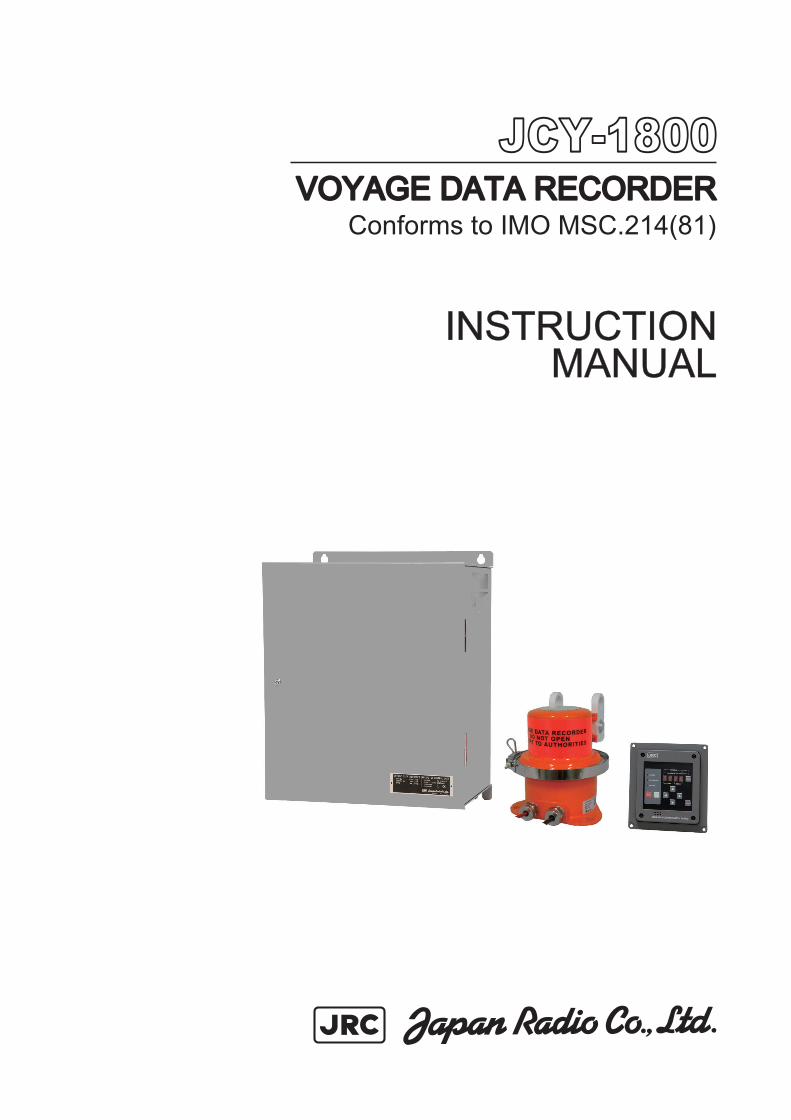
JCY-1800JCY-1800VOYAGE DATA RECORDERVOYAGE DATA RECORDER
INSTRUCTIONINSTRUCTIONMANUALMANUAL
01ETM ISO 9001, ISO 14001 Certified
Printed in Japan
Marine Service [email protected]
Telephone :Facsimile :e-mail :
AMSTERDAM BranchTelephone :Facsimile :e-mail :
SEATTLE BranchTelephone :Facsimile :e-mail :
CODE No.7ZPJD0385CODE No.7ZPJD0385B
MAYMAY. 2008 Edition 1 JRC. 2008 Edition 1 JRC
Not use the asbestos
For further information,contact:
URL http://www.jrc.co.jp
Conforms to IMO MSC.214(81)


Preface
i
Thank you for buying JRC JCY-1800 Voyage Data Recorder (VDR).
This equipment helps the investigators to detect the cause of marine accident to prevent the recurrence in the future. The equipment records voyage data, as required by the International Standard, during the navigation and the hull data of the vessel.
• To ensure your VDR provide optimum satisfaction and service, read this manual carefully before attempting to operate the JCY-1800.
• We recommend you to carefully store the manual for future reference.
• If you have any problems using this product, this manual will surely help you.
In order to detect the cause of marine accident, the VDR records hull data and navigation data. If an accident has occurred, it is mandatory to preserve the record data immediately. In case an accident has occurred, please preserve the record data according to the procedure described in 1.4.4: “Actions to be taken at the time of an accident” To ensure the proper operation, we recommend you to read the procedure carefully.
ATTENTION VDR erases older data that has passed for more than 12 hours and overwrites the new. Therefore if you do not operate properly, the recorded data at the time of accident will be erased automatically after 12 hours.
Preface
ii
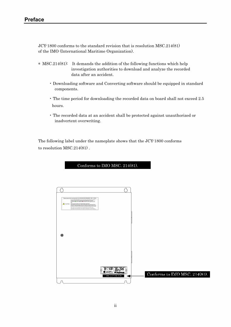
JCY-1800 conforms to the standard revision that is resolution MSC.214(81) of the IMO (International Maritime Organization). * MSC.214(81): It demands the addition of the following functions which help
investigation authorities to download and analyze the recorded data after an accident.
• Downloading software and Converting software should be equipped in standard components.
• The time period for downloading the recorded data on board shall not exceed 2.5 hours.
• The recorded data at an accident shall be protected against unauthorized or inadvertent overwriting.
The following label under the nameplate shows that the JCY-1800 conforms to resolution MSC.214(81) .
Conforms to IMO MSC. 214(81).
Please preserve the recording data of the VOYAGE DATA RECORDER ( VDR / S-VDR )
Press the CARD STOP SWITCH on the internal Main Control Board for about 10 seconds to preserve the recorded data in the CF CARD after an incident. The CARD LED ○ and the MEDIA LED ○ will blink for preserving the recorded data.
Please contact and follow your ships Authorities instructions. If the Authority instructs you to stop recording further data and proceed to the next port for later downloading of data by an Authority Inspector, please turn off the power to the VDR/S-VDR at the power switchboard to preserve the recording.
Note: If the unit is not switched off, the recorded data of the incident will be automatically overwritten after 12 hours further recording and it is required that ships preserve the recorded data of the incident by International rules and regulations.
CAUTION

Before Operation
iii
SYMBOL MARKS
In this manual, and on the product, we use international warning signs to call your attention to important items that, if not handled correctly, can present danger to yourself or property. These warning note classifications are shown below. Understand the meanings of the signs before proceeding to read the manual.
Examples of Symbol Marks
The symbol indicates that it calls for a caution or even a warning.
The illustration in the symbol indicates what should be watched out for. In this case, you have to pay attention to electric shock.
The symbol indicates prohibition.
What is prohibited is depicted in or around the symbol. The sign in the left indicates that disassembly is prohibited.
The symbol indicates a specific action to be taken or an instruction to be followed, which is depicted in the symbol.
The sign in the left requests you to disconnect the electrical plug from the outlet.
Warning Labels
Do not remove, damage, or alter the labels attached to the equipment.
WARNING Indicates warning items that, if ignored, may result in serious personal injury or even death.
Indicates cautionary items that, if ignored, may result in personal injury or physical damage.
CAUTION
Electric shock
Disassembly prohibited
Remove Plug
DANGER Indicates danger items that, if ignored, may result in serious personal injury or even death.

Precautions
iv
The Power Supply Unit (NBL-327) of this equipment incorporates a battery.
The battery contains dilute sulfuric acid. When the leaked liquid of the battery had a direct contact with your clothes or skin, wash off with clean water. When the liquid infringes into your eye, wash with clean water immediately then go to a doctor.
Do not disassemble or remodel this equipment.
Such an action may result in a fire, an electric shock, or fault of the equipment.
Do not use any power supply voltage other than the specified one.
Such an action may result in a fire, an electric shock, or an equipment fault.
Turn off the power supply switch before connecting or disconnecting the cable to any external equipment.
Ignoring the caution may result in a fire or an electric shock.
If the power supply cable is damaged, please ask for the replacement to the Sales Department, the nearest branch company, branch office, sales office, or any agent of Japan Radio Co., Ltd. The use of damaged cable may result in a fire or an electric shock.
Never short-circuit the + and – pins. Never disassemble, modify, destroy, throw
into fire, heat, use with non-specified applications and use after the expiry date.
Above acts may cause leakage of fluid, generation of heat, fire, explosion, destruction, or injury by heat.
Precautions
v
If water enters into the equipment, turn off the power supply switch, pull out the
plug from the outlet, and contact the Sales Department, the nearest branch company, branch office, sales office, or any agent of Japan Radio Co., Ltd.
The water inside the equipment may result in a fire, an electric shock, or a fault.
Do not attempt checking or repairs on the internal part of the equipment by yourself.
Checking or repairs by anyone other than qualified maintainer may result in a fire or an electric shock.
Ask for internal check or repairs of the equipment to the Sales Department, the nearest branch company, branch office, sales office, or any agent of Japan Radio Co., Ltd.
If a fault has occurred, turn off the power supply of the equipment, pull out the plug, and contact the Sales Department, the nearest branch company, branch office, sales office, or any agent of Japan Radio Co., Ltd.
The continuous use of the equipment may result in a fire or an electric shock.
The Recording Control Unit (NDV-1800) of this equipment incorporates a battery. The battery needs to be replaced periodically. Continuous use of a life-expired battery may result in a fire.
Never replace the battery by yourself.
Replacement by anyone other than qualified maintainer may result in a fire, an electric shock, or a fault.
For battery replacement, contact the Sales Department, the nearest branch company, branch office, sales office, or any agent of Japan Radio Co., Ltd.
The Recording Control Unit (NDV-1800) of this equipment incorporates a battery.
Used batteries are to be recycled. Regarding the replacement and recycle, contact the Sales Department, the nearest branch company, branch office, sales office, or any agent of Japan Radio Co., Ltd. and ask them the replacement and recycle.
The Main Control Board (CDJ-2304), the Remote Maintenance Board (CDK-287) and the Underwater Acoustic Beacon on the PCU of this equipment incorporate a lithium battery.
Used batteries are to be recycled. Regarding the replacement and recycle, contact the Sales Department, the nearest branch company, branch office, sales office, or any agent of Japan Radio Co., Ltd. and ask them the replacement and recycle.
When disposing of this unit, abide by the local laws and regulations. Contact the Sales Department, the nearest branch company, branch office, sales office, or any agent of Japan Radio Co., Ltd. and ask them to replace it without discarding the battery.
Precautions
vi
Do not remove, damage, or alter the labels attached to the equipment.
Do not install the equipment, if the location is infringed by water, humid, dusty, or with soot.
Ignoring the caution may result in a fire, an electric shock, or a malfunction.
Hands off the equipment if your hand or glove is wet either with freshwater or seawater.
Ignoring the caution may result in a fire, an electric shock, or a fault.
Be sure to hold the power supply plug when pulling it out from the outlet.
Pulling the electric cable without holding the plug can damage the cable, resulting in a fire or an electric shock.
Do not remove or insert the power supply plug with wet hand.
Ignoring the caution may result in an electric shock.
Although the UTILITY OUTLET looks like the one of AC100V, the input voltage of the Recording Control Unit directly comes out from it.
i.e; In case the 220VAC is supplied, the same voltage comes out from UTILITY OUTLET. Ignoring the caution may result in failures.
If the FAN ABNORMAL LED lights up, either of the two fans of the Power Supply Unit is out of order and needs to be replaced. Ignoring the caution may result in failures. Contact the Sales Department, the nearest branch company, branch office, sales office, or any agent of Japan Radio Co., Ltd. and ask them to replace it.
If the equipment is splashed either with seawater or fresh water, wipe it dry immediately. Ignoring the caution may result in failures or operational malfunctions.
Do not use organic solvent such as thinner or benzine to clean the surface. These agents damage the surface coating.
Be sure to remove dirt and dust, if any, from the surface and wipe it with a clean dry cloth.

Exterior of System Components
vii
Recording Control Unit Protective capsule Unit Operation Panel Unit

Contents
viii
Contents
Preface ............................................................................................................................................. i Before Operation ...........................................................................................................................iii Precautions.................................................................................................................................... iv Exterior of System Components ..................................................................................................vii Abbreviations ................................................................................................................................ xi Glossary ........................................................................................................................................xii
1. Operation.................................................................................................................................. 1
1.1 Outline of the Equipment ................................................................................................... 1 1.2 Configuration....................................................................................................................... 1
1.2.1 System diagram............................................................................................................ 3 1.3 Starting and Stopping the System ..................................................................................... 4
1.3.1 Starting the system......................................................................................................4 1.3.2 Stopping the system..................................................................................................... 6
1.4 Detailed Operation Instructions......................................................................................... 7 1.4.1 To stop recording data onto the protective capsule unit............................................. 7 1.4.2 To restart recording data onto the protective capsule unit ........................................ 7 1.4.3 Backing up the data of CF CARD................................................................................ 7 1.4.4 Protecting against overwriting data in CF CARD...................................................... 8 1.4.5 Actions to be taken at the time of an accident (Guidelines)....................................... 9 1.4.6 Silencing the audible alarm on the Operation Panel Unit ....................................... 10
1.5 Recording Control Unit (NDV-1800)................................................................................. 11 1.5.1 Parts name on Recording Control Unit (NDV-1800)................................................. 11 1.5.2 Power Supply Unit ..................................................................................................... 13 1.5.3 Data Processor Unit ................................................................................................... 16
1.6 Operation Panel Unit (NCG-169) ..................................................................................... 20 1.6.1 Names of parts on the External Operation Board .................................................... 20 1.6.2 How to operate Operation Panel Unit (Normal mode) ............................................. 22 1.6.3 How to operate Operation Panel Unit (on NSK mode)............................................. 28

Contents
ix
2. Specification ........................................................................................................................... 29
2.1 Protective Capsule Unit: PCU (NDH-316A/316)................................................................ 29 2.2 Recording Control Unit: RCU (NDV-1800)......................................................................... 30
2.2.1 Operation panel (Internal)............................................................................................ 30 2.2.2 Data Processor Unit ...................................................................................................... 30 2.2.3 Power Supply Unit: PSU .............................................................................................. 32 2.2.4 External Interface ......................................................................................................... 32 2.2.5 Environmental condition .............................................................................................. 32 2.2.6 General specification..................................................................................................... 33 2.2.7 NSK Interface (Option)................................................................................................. 33 2.2.8 Radar switching recording function ............................................................................. 33
2.3 Operation Panel Unit: OPU (NCG-169) ............................................................................. 35 2.4 Microphone Unit (NVT-161)................................................................................................ 35 2.5 Connection Box (NQE-3163) ............................................................................................... 36 2.6 Waterproof Microphone Unit (NVT-162) -Option-.............................................................. 36 2.7 Digital Signal Converter (NCT-72) 64CH -Option- ............................................................ 36 2.8 Digital Signal Converter (NCT-63) 16CH -Option- ............................................................ 37 2.9 Radar Interface Unit (NWP-46) -Option- ........................................................................... 38 2.10 General Environmental Condition of Use ........................................................................ 39
2.10.1 Condition of Use ......................................................................................................... 39 2.10.2 Power Supply Environment Conditions .................................................................... 39 2.10.3 Environmental Condition .......................................................................................... 40
3. Maintenance and Inspection ......................................................................................................... 41
3.1 Daily Maintenance ............................................................................................................ 41 3.1.1 Cleaning...................................................................................................................... 41 3.1.2 Checking the expiry date of battery .......................................................................... 41
3.2 Periodic Inspection ............................................................................................................ 42 3.3 Troubleshooting ................................................................................................................. 43
3.3.1 Recording Control Unit (NDV-1800).......................................................................... 43 3.3.2 Operation Panel Unit (NCG-169) .............................................................................. 45

Contents
x
4. After-sales Service ........................................................................................................................ 49
4.1 To request the service ........................................................................................................ 49 4.2 Disposal of unit .................................................................................................................. 51 4.3 Disposal of used battery .................................................................................................... 51
5. Outside Drawings .......................................................................................................................... 53
5.1 Recording Control Unit: NDV-1800 .................................................................................. 53 5.2 Operation Panel Unit: NCG-169....................................................................................... 54 5.3 Protective Capsule Unit: NDH-316A / 316....................................................................... 55 5.4 Connection Box: NQE-3163 .............................................................................................. 57 5.5 Microphone Unit: NVT-161 ............................................................................................... 58 5.6 Waterproof Microphone Unit: NVT-162 ............................................................................ 59 5.7 Digital Signal Converter: NCT-72 (64ch) ......................................................................... 60 5.8 Digital Signal Converter: NCT-63 (16ch) ......................................................................... 61 5.9 Radar Interface Unit: NWP-46 ......................................................................................... 62
6. Block Diagrams ............................................................................................................................. 65
6.1 Recording Control Unit NDV-1800 ................................................................................ 65 6.2 Operation Panel Unit NCG-169 ..................................................................................... 66 6.3 Microphone Unit NVT-161 ............................................................................................. 67 6.4 Waterproof Microphone Unit NVT-162 .......................................................................... 68 6.5 Digital Signal Converter (CH64) NCT-72 ...................................................................... 69 6.6 Digital Signal Converter (CH16) NCT-63 ...................................................................... 71 6.7 Radar Interface Unit NWP-46........................................................................................ 73
Abbreviations
xi
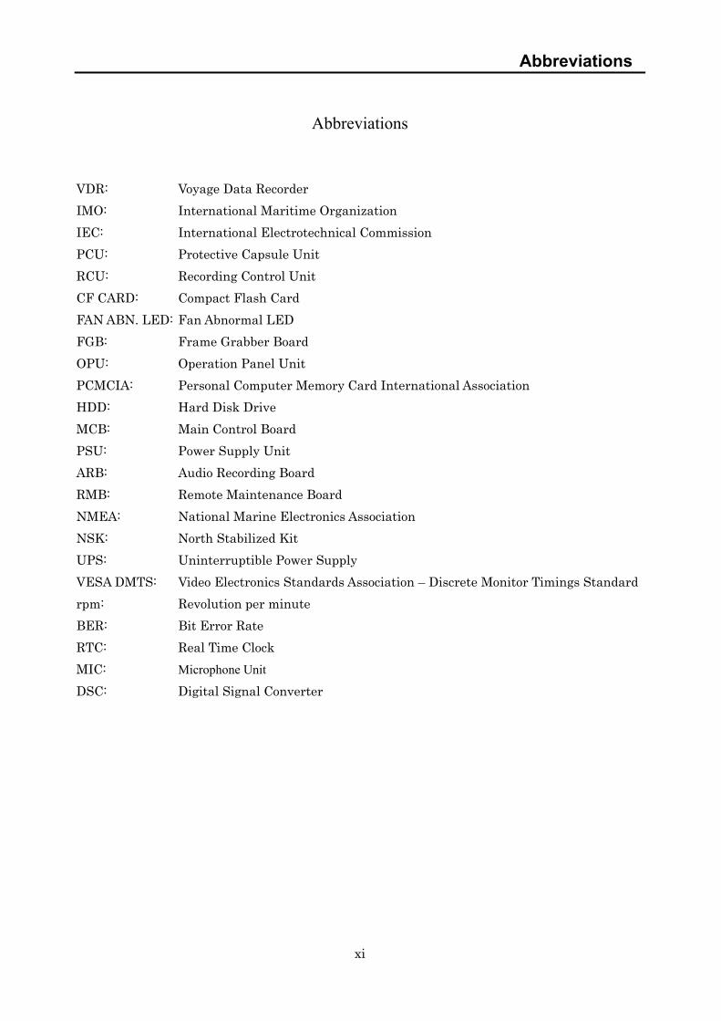
Abbreviations VDR: Voyage Data Recorder IMO: International Maritime Organization IEC: International Electrotechnical Commission PCU: Protective Capsule Unit RCU: Recording Control Unit CF CARD: Compact Flash Card FAN ABN. LED: Fan Abnormal LED FGB: Frame Grabber Board OPU: Operation Panel Unit PCMCIA: Personal Computer Memory Card International Association HDD: Hard Disk Drive MCB: Main Control Board PSU: Power Supply Unit ARB: Audio Recording Board RMB: Remote Maintenance Board NMEA: National Marine Electronics Association NSK: North Stabilized Kit UPS: Uninterruptible Power Supply VESA DMTS: Video Electronics Standards Association – Discrete Monitor Timings Standard rpm: Revolution per minute BER: Bit Error Rate RTC: Real Time Clock MIC: Microphone Unit DSC: Digital Signal Converter

Glossary
xii
Glossary
A.861: IMO Performance Standard for VDR IEC61996: Performance Requirements for VDR IEC60945: General Requirements IEC61162: Digital Interfaces Standard HDT: Heading true sentence header ID of IEC61162-1 VBW: Dual ground/water speed sentence header ID of IEC61162-1 UXGA: Ultra eXtended Graphics Array (1600 x 1200: High resolution pixel)

1
1. Operation
1.1 Outline of the Equipment
This equipment helps to detect the cause of marine accident to prevent the recurrence in the future. The equipment records voyage data, as required by the International Standard, during the navigation and the hull data of the vessel.
1.2 Configuration
The standard configuration of the equipment is shown in Table 1.
Table 1: Standard Configuration
No. Name of Component Type Name Qty Function
1 Protective Capsule Unit
(PCU)
NDH-316A
or
NDH-316
1 Records data on the recording medium in the recovery Protective Capsule.
At the time of sinking, the underwater acoustic beacon helps the searchers to detect the position of the PCU.
The performance of NDH-316A and NDH-316 is equivalent; both models are capsule for the JCY-1800 and interchangeable.
Mounting dimensions also are the same. 2 Connection Box NQE-3163 1 Connects the PCU and the RCU with a
power supply cable and a LAN cable. 3 Recording Control Unit
(RCU)
NDV-1800 1 Outputs the recorded data to the PCU and CF CARD.
Inputs radar images, audio data and IEC61162-1/-2 data.
Monitors and controls the conditions of the system.
3-1 Data Processor Unit NDL-46 1 Main control processing part with a built-in backup CF CARD.
3-2 Audio Junction Board CQD-2041 1 An I/F of audio input from the Microphone and VHF transceiver.
3-3 Power Supply Unit (PSU) NBL-327 1 Power supply equipped with a secondary battery and a charging circuit.
4 Operation Panel Unit (OPU) NCG-169 1 Displays the status of VDR. ALARM BUZZER, an ALARM ACK switch, and LEDs are equipped.
5 Microphone Unit (MIC) NVT-161
3 Records the conversation in the bridge and outputs the audio to the RCU.
Accessories
6 Spare Parts for RCU 7ZXJD0080 1 Spares for the NDV-1800 Fans, Fuse
7 CF Card adapter SLCFADU 1 for record data playback
8 LAN cable KB-10T5-03LBK 1 3m
9 Playback software CYC-315A 1
Only for the use by the Investigation Authorities.
Attached inside the NDV-1800. 10 Playback Software /
Real Time Monitor
CYC-316A 1
For the User. Attached inside the NDV-1800.
1. Operation
2
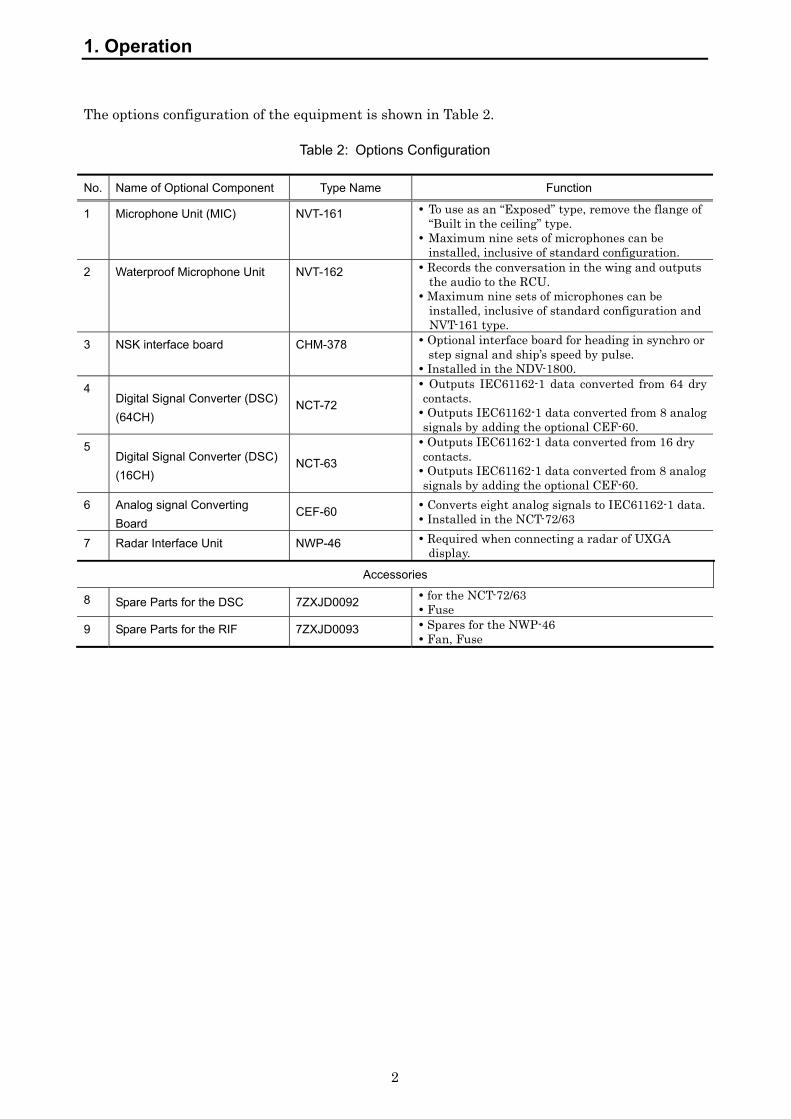
The options configuration of the equipment is shown in Table 2.
Table 2: Options Configuration
No. Name of Optional Component Type Name Function
1 Microphone Unit (MIC) NVT-161
To use as an “Exposed” type, remove the flange of “Built in the ceiling” type.
Maximum nine sets of microphones can be installed, inclusive of standard configuration.
2 Waterproof Microphone Unit NVT-162 Records the conversation in the wing and outputs the audio to the RCU.
Maximum nine sets of microphones can be installed, inclusive of standard configuration and NVT-161 type.
3 NSK interface board CHM-378 Optional interface board for heading in synchro or step signal and ship’s speed by pulse.
Installed in the NDV-1800. 4
Digital Signal Converter (DSC) (64CH)
NCT-72
Outputs IEC61162-1 data converted from 64 dry contacts. Outputs IEC61162-1 data converted from 8 analog signals by adding the optional CEF-60.
5 Digital Signal Converter (DSC) (16CH)
NCT-63
Outputs IEC61162-1 data converted from 16 dry contacts. Outputs IEC61162-1 data converted from 8 analog signals by adding the optional CEF-60.
6 Analog signal Converting Board
CEF-60 Converts eight analog signals to IEC61162-1 data. Installed in the NCT-72/63
7 Radar Interface Unit NWP-46 Required when connecting a radar of UXGA display.
Accessories
8 Spare Parts for the DSC 7ZXJD0092 for the NCT-72/63 Fuse
9 Spare Parts for the RIF 7ZXJD0093 Spares for the NWP-46 Fan, Fuse

1. Operation
3
1.2.1 System Diagram Figure 1 The system diagram of the equipment.
Figure 1: System Diagram
*Mic-1
VHF Telephone No.1 *
* AC220V 60Hz 1 phase
Mic-4 *
*Mic-2
*VHF Telephone No.2
MIC1
MIC2
MIC4
*
****
*
RGBH synch
V synch
*Mic-5MIC5
Mic-7 *MIC7(W.P.)
*Mic-8MIC8(W.P.) Gyro Compass [STEP](Yard)
*
Gyro Compass [Synchro](Yard)
*
Speed Log [Pulse](Yard)
*
DGPS(Yard)
*
AIS(Yard)
*
Speed Log(Yard)
*
Gyro Compass(Yard)
*
Auto Pilot(Yard)
*
Rudder Angle Indicator(Yard)
*
Echo Sounder(Yard)
*
Anemometer(Yard)
*
Engin Telegraph(Yard)
*
Remote Control System (Yard)
*
Other(Yard)
*
X-Band Radar (JRC)
*
*
*
From AC Distributor
Dry Contact(Yard)
*
*
From AC Distributor
Dry Contact(Yard)
Other(Yard)
*
Other (Yard)
*
* Analog(Yard)
* Analog(Yard)
1. Operation
4
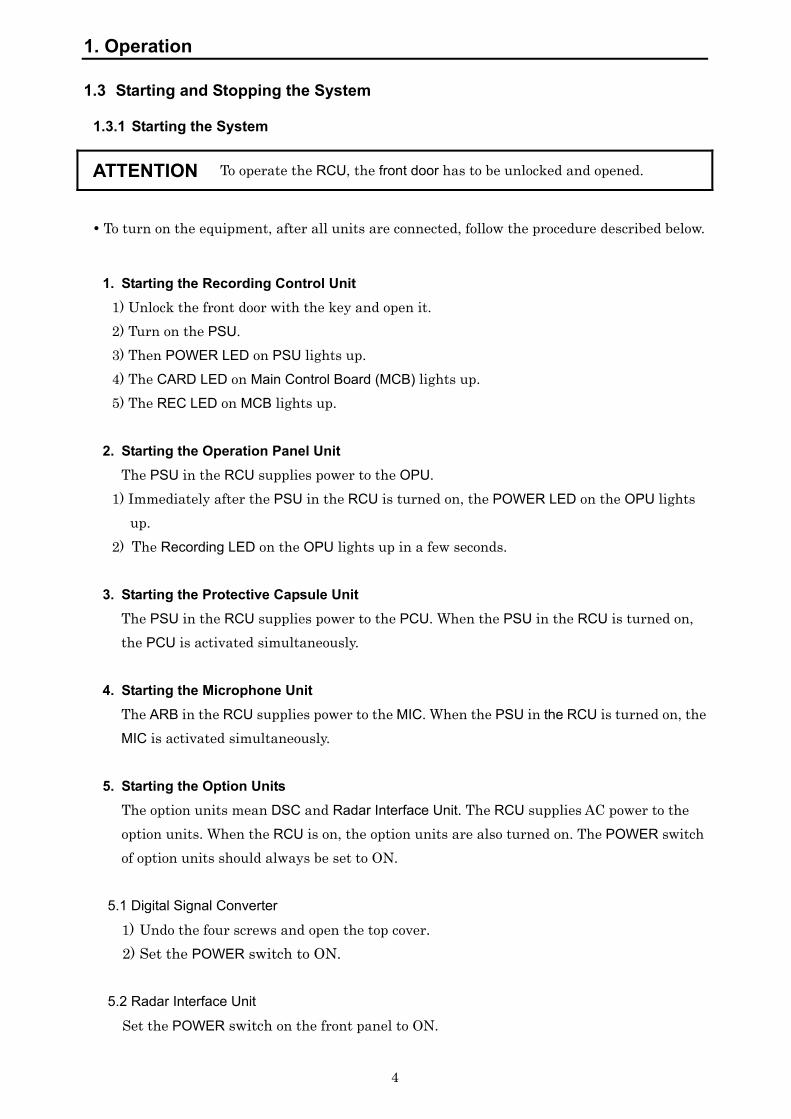
1.3 Starting and Stopping the System
1.3.1 Starting the System
ATTENTION To operate the RCU, the front door has to be unlocked and opened.
To turn on the equipment, after all units are connected, follow the procedure described below.
1. Starting the Recording Control Unit 1) Unlock the front door with the key and open it. 2) Turn on the PSU. 3) Then POWER LED on PSU lights up. 4) The CARD LED on Main Control Board (MCB) lights up. 5) The REC LED on MCB lights up.
2. Starting the Operation Panel Unit
The PSU in the RCU supplies power to the OPU. 1) Immediately after the PSU in the RCU is turned on, the POWER LED on the OPU lights
up. 2) The Recording LED on the OPU lights up in a few seconds.
3. Starting the Protective Capsule Unit
The PSU in the RCU supplies power to the PCU. When the PSU in the RCU is turned on, the PCU is activated simultaneously.
4. Starting the Microphone Unit
The ARB in the RCU supplies power to the MIC. When the PSU in the RCU is turned on, the MIC is activated simultaneously.
5. Starting the Option Units
The option units mean DSC and Radar Interface Unit. The RCU supplies AC power to the option units. When the RCU is on, the option units are also turned on. The POWER switch of option units should always be set to ON.
5.1 Digital Signal Converter
1) Undo the four screws and open the top cover. 2) Set the POWER switch to ON.
5.2 Radar Interface Unit
Set the POWER switch on the front panel to ON.
1. Operation
5
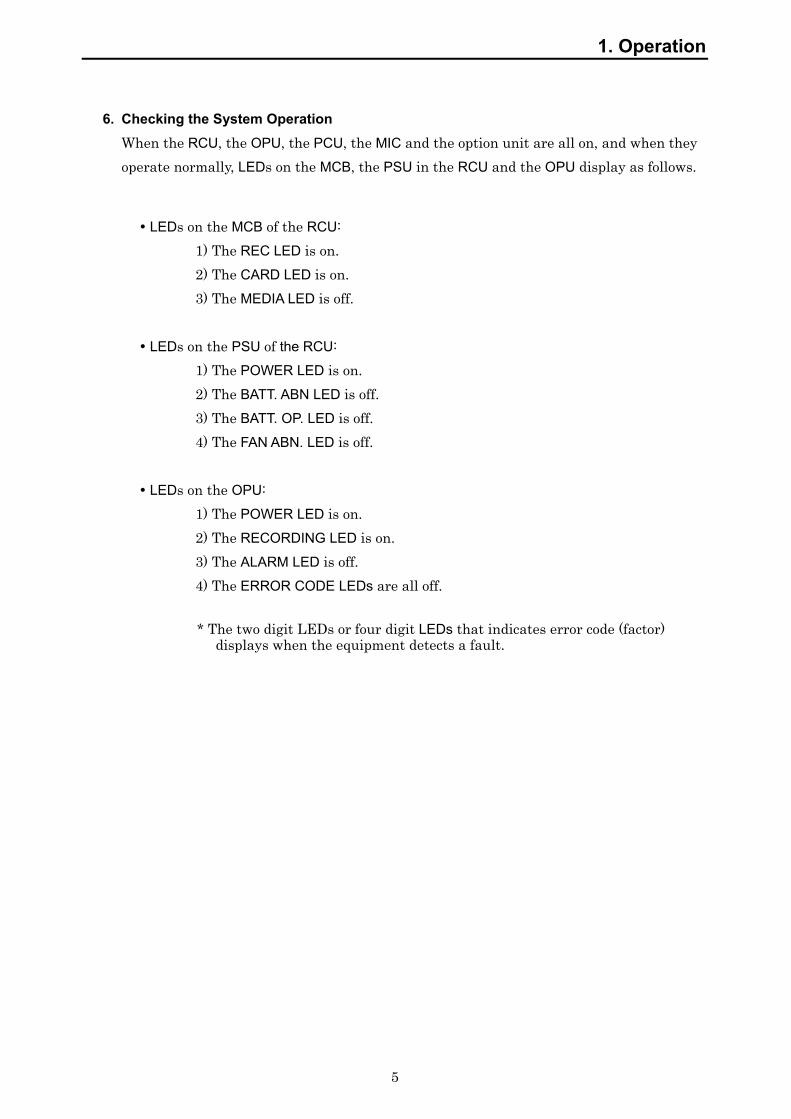
6. Checking the System Operation
When the RCU, the OPU, the PCU, the MIC and the option unit are all on, and when they operate normally, LEDs on the MCB, the PSU in the RCU and the OPU display as follows.
LEDs on the MCB of the RCU: 1) The REC LED is on. 2) The CARD LED is on. 3) The MEDIA LED is off.
LEDs on the PSU of the RCU: 1) The POWER LED is on. 2) The BATT. ABN LED is off. 3) The BATT. OP. LED is off. 4) The FAN ABN. LED is off. LEDs on the OPU: 1) The POWER LED is on. 2) The RECORDING LED is on. 3) The ALARM LED is off. 4) The ERROR CODE LEDs are all off.
* The two digit LEDs or four digit LEDs that indicates error code (factor) displays when the equipment detects a fault.

1. Operation
6
1.3.2 Stopping the System
To stop the equipment, follow the procedures described below.
ATTENTION To operate the RCU, the front door has to be unlocked and opened.
ATTENTION Do not turn off the breaker of the power distribution board while the system is active. Otherwise, the system is battery-operated by PSU.
ATTENTION Before turning off RCU, be sure to stop recording data to CF CARD by pressing CARD STOP switch on MCB. Otherwise, data may not be able to be recorded to CF CARD.
1. Stopping the Recording Control Unit 1) Unlock the front door with the key and open it. 2) Be sure to stop recording data to the CF CARD by pressing the CARD STOP switch on
the MCB. Make sure that the CARD LED on the MCB is off. Be aware that if the Power Supply is turned off while the CARD LED is on, data may
not be recorded to the CF CARD. 3) Turn off the Power switch of the PSU. 4) Then all the LEDs are turned off.
2. Stopping the Operation Panel Unit If the PSU in the RCU is turned off, the OPU is also turned off.
3. Stopping the Protective Capsule Unit If the PSU in the RCU is turned off, the PCU is also turned off.
4. Stopping the Microphone Unit If the PSU in the RCU is turned off, the MIC is also turned off.
5. Stopping the Option Units If the PSU in the RCU is turned off, the Option Units are also turned off.

1. Operation
7
1.4 Detailed Operational Description
In this section the basics of operation are explained. The operations can be performed on the MCB of the RCU. (To have access to the RCU, the front door has to be unlocked and opened.)
1.4.1 To Stop Recording Data onto the Protective Capsule Unit
ATTENTION Do not stop recording data into PCU unless any of the following situations has arisen. while the vessel is in port for essential maintenance purposes. when the vessel is laid-up. (docked in) upon request by an investigation authority, for example after the vessel had been involved in a marine incident.
1) Press the REC STOP switch on the MCB. 2) The REC LED on the MCB blinks. 3) After about a minute, the blinking REC LED on the MCB and RECORDING LED on the
OPU are turned off and the recording of the data onto the PCU stops. 4) When the RCU stops recording to the PCU, the Recording Alarm is generated. (Error
code: 22__) 5) When the RCU starts recording to the PCU, the Recording Alarm is canceled. (Error
code: 22__)
1.4.2 To Restart Recording Data onto the Protective Capsule Unit
ATTENTION Once recording is halted while in port or dock, make sure to restart recording when leaving the port. Otherwise, no data will be found recorded even when an accident has occurred.
1) Press the REC START switch on the MCB.
2) The REC LED on the MCB lights up.
3) The RECORDING LED on the OPU lights, and the recording of the data onto the PCU starts.
4) When the RCU starts recording to the PCU, the Recording alarm becomes normal.
1.4.3 Backing Up the Data of the CF CARD
1) Make sure that the CARD LED on the MCB is on. 2) Press the CARD STOP switch on the MCB. 3) The CARD LED on the MCB blinks for about 5 seconds.

1. Operation
8
4) Make sure that the CARD LED on the MCB is turned off. And press the CF CARD EJECT
BUTTON. 5) Take out the CF CARD. Insert the card with a CARD ADAPTER into the PC that has a
PCMCIA slot and copy the data into the PC. 6) After the copy has been finished, insert the CF CARD into the CARD slot on the MCB.
(Be sure that the JRC-label side is pointing right on the CF CARD) 7) Make sure that the CARD LED lights up.
ATTENTION When the CARD LED is left turned off for 10 minutes or more, the MEDIA LED lights up on the MCB and the OPU gives the alarm with alarm buzzer. ALARM lamp and ERROR CODE LEDs will be blinking. (Error Code: 31__) If a CF CARD is inserted into the CARD slot in the MCB, the alarm buzzer stops and ALARM LEDs will be off.
ATTENTION If the backup to CF CARD is likely to be made frequently, purchase of one more card is recommended. (CF Card code: 7HRJD0002)
1.4.4 Protecting against overwriting data on CF CARD JCY-1800 can protect recorded data on CF CARD against unauthorized or inadvertent overwriting after a marine accident. Recording data does not start onto protected CF
CARD even though JCY-1800 is rebooted or CF CARD is taken out and put into JCY-1800.
ATTENTION JCY-1800 does not stop recording data to PCU. When a marine accident occurs, refer to Section 1.4.5 “Actions to be taken at the time of an accident (Guidelines)”.
1. Protecting against overwriting data on CF card
1) Press CARD STOP switch on MCB until CARD LED and MEDIA LED start flashing (approx. 10 seconds).
2) The CF CARD is protected against overwriting data. Flashing of both CARD LED and MEDIA LED shows that the CF CARD is prohibited against overwriting and protected. Also, OPU generates error alarm as protecting against overwriting CF CARD (Error code: 03__). Press ACK switch on OPU for stopping the alarm buzzer.
2. Releasing the protection of CF CARD In the following cases, release the protection of CF CRAD in order to start recording data onto CF CARD.
1. Operation
9
• It becomes unnecessary to preserve the recorded data of accident after transferring the protected data to relevant investigation authorities.
• The recorded data in CF CARD have been protected by mistake.
1) Insert CF CARD protected overwriting into CARD slot on MCB. 2) Both CARD LED and MEDIA LED on MCB flash. 3) Press REC START switch on MCB until CARD LED lights up (approx. 10 seconds). 4) The overwriting protection of CF CARD is released and JCY-1800 starts recording
data onto CF CARD. The error display (Error code: 03__) on OPU is canceled.
1.4.5 Actions to be taken at the time of an accident (Guidelines)
When a marine accident occurs, it is mandatory to store the recorded data of hull and navigation information until the time of the accident. This section shows some guidelines on how to preserve the data. After careful check of the situation of the accident, attempt to preserve the data. The relevant authority requires the submission of the preserved data. For transferring the control of the data, contact the Sales Department of Japan Radio Co., Ltd.
1. Preserving the recorded data on CF CARD
Step Actions Operation on RCU
1 Preserve recorded data by protecting CF CARD at the time of an accident.
Press CARD STOP switch on MCB until CARD LED and MEDIA LED start flashing (approx. 10 seconds). (Refer to Section 1.4.4)
2 Eject CF CARD from RCU. Press CARD EJECT button.
3 Copy the recorded data from the CF CARD onto HDD of PC. *1
Check the copied data. (Each folder name under the Log/Audio/Visual shows the date and time when the data were recorded.)
4 Return CF CARD into RCU after copying.
Confirm both CARD LED and MEDIA LED start flashing.
*1 Copy all folders and files on CF CARD onto HDD of PC. “Copy” the recorded data, not to “move” (cut and paste) them. Do not delete the preserved data on CF CARD until the preserved data in accident are transferred to relevant authorities.

1. Operation
10
Submit the DVD on which the data of the accident on HDD of PC burnt, when the relevant authority requires the preserved data. When submitting the preserved CF CARD to the authority, an alternative CF CARD will be necessary. If that is the case, contact the Sales Department of Japan Radio Co., Ltd. When the investigator of relevant authority boards, the investigator downloads the preserved data from CF CARD in VDR. Always return the overwriting-protected CF
CARD to RCU.
2. Preserving the recorded data in Protective Capsule Unit
If the relevant authority instructs you to stop recording further data and proceed to the next port for later downloading of data by the authority’s investigator, stop recording onto PCU.
Step Actions Operation of RCU
1 Stop VDR system. Turn off POWER switch.
(Refer to Section 1.5.2.)
If the key to open the front door of RCU is misplaced or lost, turn off the power to VDR at power switchboard to preserve the recorded data. After 2 hours of turning it off, it automatically stops recording and becomes power OFF.
ATTENTION The danger of life to the crew is pressing as the accident is very serious… Escape from the vessel first. Leave VDR as it is. VDR automatically stops recording data after 2 hours of the main power cut.(When the evacuation is necessary due to the accident, the operation to preserve recorded data is not necessary.) PCU will be collected and the recorded data will be obtained therewith.
ATTENTION To copy data from CF CARD, the PC with PCMCIA slot and 2GB of available volume on HDD are needed. If the vessel does not have the PC which meets such conditions, contact our business office. A standard laptop PC has a PCMCIA slot.
1.4.6 Silencing the Audible Alarm on the Operation Panel Unit In case the alarm buzzer on the OPU sounds:
1) Press the ACK switch on the OPU. 2) Then the alarm buzzer on the OPU stops. 3) If more than one alarm are detected, press the ACK switch as many times as the alarms
are detected.
1. Operation
11
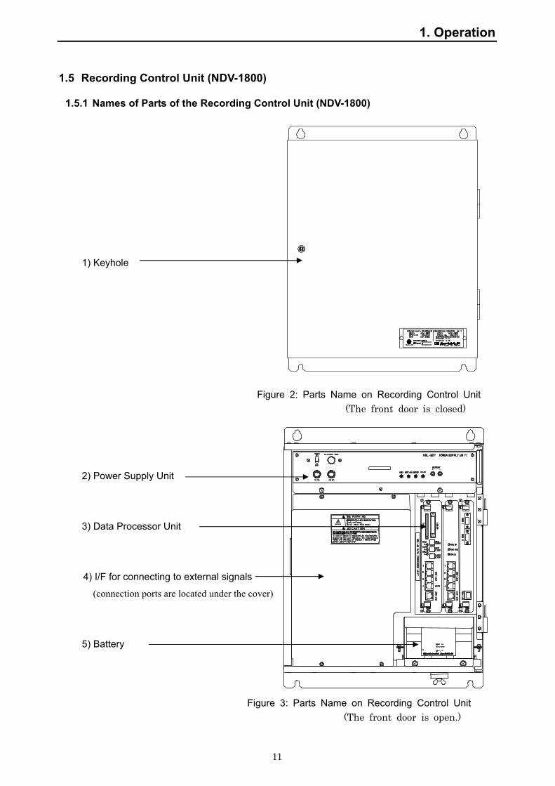
1.5 Recording Control Unit (NDV-1800)
1.5.1 Names of Parts of the Recording Control Unit (NDV-1800)
1) Keyhole
Figure 2: Parts Name on Recording Control Unit
(The front door is closed)
2) Power Supply Unit
3) Data Processor Unit
4) I/F for connecting to external signals
(connection ports are located under the cover)
5) Battery
Figure 3: Parts Name on Recording Control Unit (The front door is open.)

1. Operation
12
Table 3: Names and Functions of the RCU
No. Names and Functions 1) Keyhole:
Used for opening and closing the front door. 2) Power Supply Unit :
Incorporated into the RCU. It has an external battery and supplies power to PCU, OPU and MIC in case of power failure.
3) Data Processor Unit: The main processing unit of the RCU. It has a CARD slot for a backup CF CARD.
4) I/F for connecting external signals: • RGB Connector Panel: RGB connector relay panel for connecting to the RADAR (BNC connector)
• AUDIO Interface Board: Interface board for connecting to the MICs and VHF • Terminals: Terminals for inputting IEC61162-1/2 signals and connecting to the PCU and the OPU
• Utility Outlet: The electricity outlet for maintenance facilities (AC100-240V)
5) Battery: Battery is connected to the PSU. Supplies DC24V power for 2 hours to the RCU, the PCU, the OPU and the MIC.
CAUTION
Although the UTILITY OUTLET looks like the one of AC100V, the input voltage of the RCU directly comes out from it.
i.e; In case the 220VAC is supplied, the same voltage comes out from UTILITY OUTLET. Ignoring the caution may result in failures.
1. Operation
13
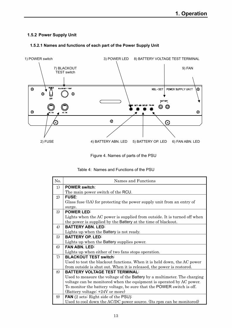
1.5.2 Power Supply Unit
1.5.2.1 Names and functions of each part of the Power Supply Unit
1) POWER switch 3) POWER LED 8) BATTERY VOLTAGE TEST TERMINAL
2) FUSE 4) BATTERY ABN. LED 5) BATTERY OP. LED 6) FAN ABN. LED
Figure 4. Names of parts of the PSU
Table 4: Names and Functions of the PSU
No. Names and Functions 1) POWER switch:
The main power switch of the RCU. 2) FUSE:
Glass fuse (5A) for protecting the power supply unit from an entry of surge.
3) POWER LED: Lights when the AC power is supplied from outside. It is turned off when the power is supplied by the Battery at the time of blackout.
4) BATTERY ABN. LED: Lights up when the Battery is not ready.
5) BATTERY OP. LED: Lights up when the Battery supplies power.
6) FAN ABN. LED: Lights up when either of two fans stops operation.
7) BLACKOUT TEST switch: Used to test the blackout functions. When it is held down, the AC power from outside is shut out. When it is released, the power is restored.
8) BATTERY VOLTAGE TEST TERMINAL: Used to measure the voltage of the Battery by a multimeter. The charging voltage can be monitored when the equipment is operated by AC power. To monitor the battery voltage, be sure that the POWER switch is off. (Battery voltage: +24V or more)
9) FAN (2 sets: Right side of the PSU): Used to cool down the AC/DC power source. (Its rpm can be monitored)
7) BLACKOUT TEST switch
9) FAN

1. Operation
14
1.5.2.2 How to operate Power Supply Unit
1. Starting power source: 1) Turn on the POWER switch. 2) Then the POWER LED lights up.
2. Stopping power source: 1) Before turning off the power source, press the CARD STOP switch to stop the
backup of CF CARD.
ATTENTION Before turning off the power source, be sure that the CARD LED on the MCB is off. Turning off the POWER switch while the CARD LED is on may result in the physical damage to the CF CARD. Make sure to stop the backup by pressing the CARD STOP switch.
2) Press the CARD STOP switch on the MCB. 3) Make sure that the CARD LED on the MCB is off. 4) Turn off the POWER switch. 5) Then all the LEDs are turned off.
3. Blackout Test:
1) Hold down the BLACKOUT TEST switch. (While it is held down, AC power input is cut off.)
2) While the BLACKOUT TEST switch is held down, check the following items. If they all happen, the Battery is in normal operation.
The POWER LED of the PSU is turned off. The BATTERY OP. LED of the PSU lights up. The alarm buzzer of the OPU sounds. The ALARM LED and the ERROR CODE LEDs on the OPU blinks. ( Error Code: 10__ )
The POWER LED on the OPU blinks.
3) Release the BLACKOUT TEST switch, then the following happen.
The POWER LED of the PSU lights up. The BATTERY OP. LED of the PSU is turned off. The alarm buzzer of the OPU stops sounding. The ALARM LED and the ERROR CODE LEDs on the OPU are turned off. The POWER LED on the OPU lights up.
1. Operation
15
4. If FAN ABN. LED lights up: Follow the procedures described in 3.3: Trouble Shooting.
CAUTION
If the FAN ABN. LED lights up, either of the two fans of the PSU is out of order and needs to be replaced. Ignoring the caution may result in failures. Please contact the Sales Department, the nearest branch company, branch office, sales office, or any agent of Japan Radio Co., Ltd. and ask them to replace.

1. Operation
16
1.5.3 Data Processor Unit
1.5.3.1 Names of each part of the Data processor Unit
Figure 5: The Data Processor Unit
Table 5: Names and Functions of each BOARD in the Data Processor Unit
Board name Function MAIN CONTROL BOARD (MCB)
The main processing module of the RCU. Records all the data to the PCU and the CF CARD. Used to receive the IEC61162-1/2 signals (CH01-CH16) and AUDIO signals.
REMOTE MAINTENANCE BOARD (RMB)
Used to receive the IEC61162-1/2 signals (CH17-CH32), and send them to the MCB.
FRAME GRABBER BOARD (FGB) -Option-
Used to capture the image signals from the RADAR, compress them, and send them to the MCB via HUB.
1) REC LED
2) REC START SWITCH
17) RGB1 IN CONNECTOR
19) LAN CONNECTOR(VDR-LAN)
FRAME GRABBER BOARD MAIN CONTROL BOARD (AUDIO RECORDING BOARD on MCB)
8) CF CARD EJECT BUTTON
7) CF CARD
6) CARD STOP switch
5) MEDIA LED
4) CARD LED
3) REC STOP SWITCH
12) RMS OP. LED
10) HUB (VDR-LAN)
REMOTE MAINTENANCE BOARD
13) RMS SYS. LED
14) DATA LED
15) HUB (JRC-LAN)
18) RGB2 IN CONNECTOR
11) LAN CONNECTOR (JRC-LAN)
16) LAN CONNECTOR (EXT-LAN)
9) AUDIO IN CONNECTOR

1. Operation
17
Table 6: Names and Functions of the Data Processor Unit
No. Names and Functions 1) REC LED (MCB):
Lights up when the data are being successfully recorded into the PCU. 2) REC START switch (MCB):
Used to restart recording the data into PCU. When releasing protection of CF CARD, press REC START switch until CARD LED lights up (approx. 10 seconds).
3) REC STOP switch (MCB): Used to stop recording the data into the PCU.
4) CARD LED (MCB): Lights up when the data are being successfully recorded into the CF CARD. Turned off when the CF CARD is in operation. CARD LED flashes with MEDIA LED when recorded data in CF CARD is protected.
5) MEDIA LED (MCB): Blinks when a CF CARD is not loaded or does not record data correctly. MEDIA LED flashes with CARD LED when recorded data in CF CARD is protected.
6) CARD STOP switch (MCB): Used to stop recording the data into the CF CARD. When protecting recorded data on CF CARD, press CARD STOP switch until both CARD LED and MEDIA LED start flashing (approx. 10 seconds).
7) CF CARD (MCB): Used as an alternative record media onto which the same data as the one stored in the PCU are recorded.
8) CF CARD EJECT BUTTON (MCB): Used to remove CF CARD from the system. Confirm that CARD LED is off then press CARD STOP switch to eject the CF CARD.
9) AUDIO IN CONNECTOR (MCB): Used as a connector through which audio signals that are received from the MIC and the VHF radio equipment are input. It is connected to the Audio Junction Board of the external interface.
10) HUB (MCB): The switching HUB function with four port is built in MCB. One of the components of VDR-LAN.
11) LAN CONNECTOR (MCB): Connected to the external HUB Unit.
12) RMS OP. LED (RMB): Lights up when the RMB is operating.
13) RMS SYS. LED (RMB): Lights up when the RMB is operating abnormally.
14) DATA LED (RMB): Lights up when the RMB can not receive any data.
15) HUB (RMB): The HUB Unit with four port switching function. One of the components of JRC-LAN.
16) LAN CONNECTOR (RMB): Connected to the external HUB Unit.
17) RGB1 IN CONNECTOR (FGB): Used as a connector through which the image signals from the main RADAR are input. Connected to the RGB connector panel.
18) RGB2 IN CONNECTOR (FGB): Used as a connector through which the image signals from the sub RADAR are input. Connected to the RGB connector panel.
19) LAN CONNECTOR (FGB): Connected to the HUB Unit of the MCB.
1. Operation
18
1.5.3.2 How to operate the Data Processor Unit
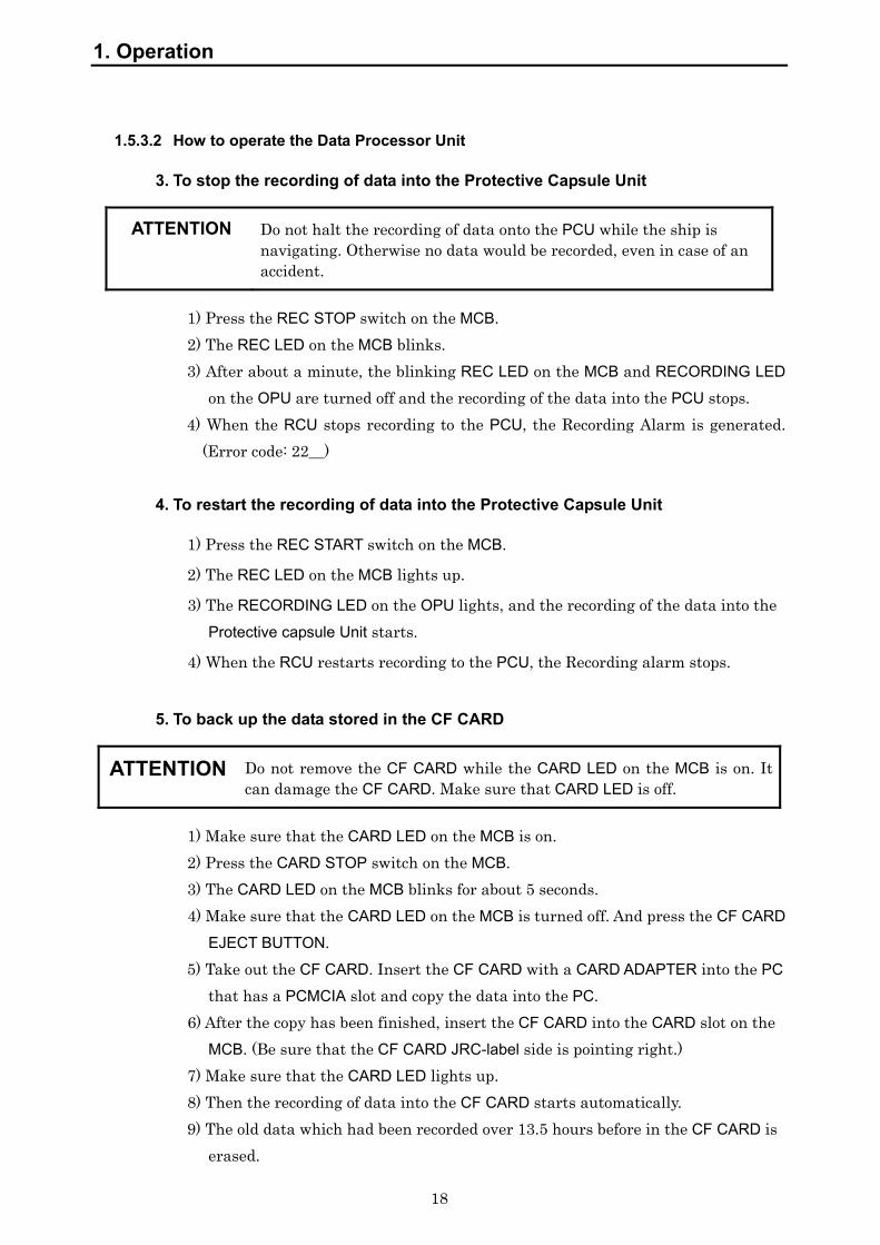
3. To stop the recording of data into the Protective Capsule Unit
ATTENTION Do not halt the recording of data onto the PCU while the ship is navigating. Otherwise no data would be recorded, even in case of an accident.
1) Press the REC STOP switch on the MCB. 2) The REC LED on the MCB blinks. 3) After about a minute, the blinking REC LED on the MCB and RECORDING LED
on the OPU are turned off and the recording of the data into the PCU stops. 4) When the RCU stops recording to the PCU, the Recording Alarm is generated.
(Error code: 22__)
4. To restart the recording of data into the Protective Capsule Unit
1) Press the REC START switch on the MCB.
2) The REC LED on the MCB lights up.
3) The RECORDING LED on the OPU lights, and the recording of the data into the Protective capsule Unit starts.
4) When the RCU restarts recording to the PCU, the Recording alarm stops.
5. To back up the data stored in the CF CARD
ATTENTION Do not remove the CF CARD while the CARD LED on the MCB is on. It can damage the CF CARD. Make sure that CARD LED is off.
1) Make sure that the CARD LED on the MCB is on. 2) Press the CARD STOP switch on the MCB. 3) The CARD LED on the MCB blinks for about 5 seconds. 4) Make sure that the CARD LED on the MCB is turned off. And press the CF CARD
EJECT BUTTON. 5) Take out the CF CARD. Insert the CF CARD with a CARD ADAPTER into the PC
that has a PCMCIA slot and copy the data into the PC. 6) After the copy has been finished, insert the CF CARD into the CARD slot on the
MCB. (Be sure that the CF CARD JRC-label side is pointing right.) 7) Make sure that the CARD LED lights up. 8) Then the recording of data into the CF CARD starts automatically. 9) The old data which had been recorded over 13.5 hours before in the CF CARD is
erased.

1. Operation
19
ATTENTION When the CARD LED is left turned off for 10 minutes or more, MEDIA LED lights up on MCB and OPU gives the alarm with alarm buzzer. ALARM lamp and ERROR CODE LEDs start blinking. (Error Code: 31__ ) If a CF CARD is inserted into the CARD slot in MCB, the alarm buzzer stops and ALARM LEDs goes out.
6. Protecting against overwriting data on CF card
1) Press CARD STOP switch on MCB until CARD LED and MEDIA LED start flashing (approx. 10 seconds).
2) The CF CARD is protected against overwriting data. Flashing of both CARD LED and MEDIA LED shows that the CF CARD is prohibited against overwriting and protected. Also, OPU generates error alarm as protecting against overwriting CF CARD (Error code: 03__). Press ACK switch on OPU for stopping the alarm buzzer.
7. Releasing the protection of CF CARD In the following situations, release the protection of CF CRAD in order to start recording data onto CF CARD.
• It becomes unnecessary to preserve the recorded data of accident after transferring the protected data to relevant investigation authorities.
• The recorded data in CF CARD have been protected by mistake.
1) Insert CF CARD protected overwriting into CARD slot on MCB. 2) Both CARD LED and MEDIA LED on MCB flash. 3) Press REC START switch on MCB until CARD LED lights up (approx. 10 seconds). 4) The overwriting protection of CF CARD is released and JCY-1800 starts recording
data onto CF CARD. The error display (Error code: 03__) on OPU is canceled.

1. Operation
20
1.6 Operation Panel Unit (NCG-169)
1.6.1 Names and functions of each part of the External Operation Board
7) HEADING LED
8) ALARM DETAIL LED
1) POWER LED 9) MODE switch
2) RECORDING LED 10) ERROR CODE LED
3) ALARM LED
11) CURSOR switch
5) ALARM ACK switch
12) ENTER switch
4) DIMMER switch
6) ALARM BUZZER
Figure 6: Operation Panel Unit
Table 7: Names and Functions of the OPU
No. Names and Functions 1) POWER LED:
Lights when the RCU is in normal operation with the power supplied from outside. Blinks when there is a blackout during the operation. If the blackout lasts, it is turned off in 2 hours. (automatic shutdown)
2) RECORDING LED: Lights when the output data from the RCU is recorded into the PCU.
3) ALARM LED: Blinks when an error(s) is (are) detected in the VDR. Pressing the ALARM ACK switch changes it from blinking to lighting. It is turned off when all the errors detected are restored to normal.
4) DIMMER switch: Controls the brightness. Press the switch then the brightness changes cyclically.
5) ALARM ACK switch: Used to stop the alarm buzzer. When more than one error are detected, press the switch as many times as the errors arose.
6) ALARM BUZZER: Sounds when an error is detected in the VDR. To silence the alarm press the ALARM ACK switch.
NCG-169 VDR OPERATION PANEL
POWER
RECORDING
ALARM
ACK DIM
HEADING
ALARM DETAIL
SYSTEM CODE
MODE
ENT
1. Operation
21
No. Names and Functions 7) HEADING LED:
Lights when the OPU is operated in NSK mode. The HEADING LED blinks when the initial value of heading is not registered. The NSK mode is usable when the optional NSK-I/F Board is installed inside RCU. If the NSK-I/F Board is not installed, the HEADING LED is turned off all the time.
8) ALARM DETAIL LED: Lights when the OPU is operated in normal mode. The ALARM DETAIL LED is always on as long as VDR is operated without any problem.
9) MODE switch: Used to change the operation mode. Press the switch then the operation mode is changed from normal mode to NSK mode or vice versa. In case the heading data is supplied in serial format, NSK mode is not necessary therefore the mode is not changed by the switch. The NSK mode is usable only when the optional NSK-I/F Board is installed in the RCU.
10) ERROR CODE LED: Four digit LEDs. They stand for ERROR code or HEADING value. • Normal mode;
The error code of four or two digits that show the error factor displays when the error occurs.
• NSK mode; HEADING value when the HEADING LED lights up.
11) CURSOR switch: Used to display the next error code when two or more errors arose or to set the initial value of heading. • Normal mode;
Press the UP/DOWN switch or RIGHT/LEFT switch in order to display other error codes.
• NSK mode; Press the RIGHT/LEFT switch to select the digit where the value is to be
altered. Press the UP/DOWN switch to select the heading value that is displayed on
ship’s Gyro. 12) ENTER switch:
Used to display the software version or to register the initial value of heading. • In Normal mode;
When ENTER switch is pressed in normal mode, The content that displays on 4 digits LED is switched to SOFTWARE VERSION display mode. When ENTER switch is pressed during SOFTWARE VERSION display mode, the operation mode returns to Normal mode of error code display. SOFTWARE VERSION display mode automatically returns to Normal mode after five minutes pass. While displaying SOFTWARE VERSION on 4 digits LED, “ALARM DETAIL LED” flashes.
• NSK mode; The entered heading angle is registered to the VDR as an initial value. The operation mode is returned to the normal mode after entry.
* Refer to the clause 1.6.3 for details of the NSK mode.

1. Operation
22
1.6.2 How to operate the Operation Panel Unit (Normal mode)
1. If an error is detected: 1) The alarm buzzer sounds if an error is detected in the VDR. 2) The ALARM LED blinks. 3) The four or two digits ERROR CODE LEDs flash. 4) Press the ALARM ACK switch until the buzzer stops. 5) Check the contents of the error code referring to table 8. 6) Follow the procedure described in 3.3: Trouble Shooting.
2. If multiple errors are detected:
1) The alarm buzzer sounds if a new error is detected in the VDR. 2) The ALARM LED blinks. 3) The latest four or two digits ERROR CODE LEDs flash. 4) Press the ALARM ACK switch until the buzzer stops. 5) When two or more errors are detected at a time, press the switch as many times as the
errors arose. 6) Check the contents of the error code referring to table 8. • Auto scroll
When multiple errors are detected, different four digits ERROR CODE LEDs light up every 3 seconds to indicate all the errors raised.
• Manual scroll Press the UP/DOWN switch or RIGHT/LEFT switch in order to change the error code.
7) Follow the procedure described in 3.3: Trouble Shooting.
3. In case of blackout: 1) The alarm buzzer sounds in case a power failure happens. 2) Both POWER LED and ALARM LED blink. 3) The ERROR CODE LEDs blink indicating “10__”. 4) Press the ALARM ACK switch to stop the buzzer. However, during the blackout, unless
the ALARM ACK switch is turned on within 2 minutes, the alarm buzzer stops of itself. 5) At the time of power failure, only the voice from the MIC is recorded. The other data
are not recorded at all. 6) If the power failure lasts 2 hours, the PSU in the RCU automatically cuts off the power
output. 7) If the detected power failure is false, follow the procedure described in 3.3: Trouble
Shooting. 8) If the blackout is restored in less than 2 hours, the RCU resumes normal operation
automatically.

1. Operation
23
4. To adjust the brightness of LEDs: 1) Press the DIMMER switch to adjust the brightness of the LEDs. 2) Press the switch again then the LEDs become darker. The brightness changes
cyclically. 3) Even at the darkest brightness, the LED is still on.
5. To check the version of the software 1) Press the ENTER switch on the OPU. 2) The operation mode is changed to the Software version display mode. 3) The ERROR CODE LEDs show the software version. 4) When the software version is shown, the ALARM DETAIL LED is blinking. 5) When the ENTER switch is pressed at this stage, the operation mode is returned to the
Normal mode. 6) Even when the ENTER switch is not pressed, the operation mode is returned to the
Normal mode in five minutes.
1. Operation
24
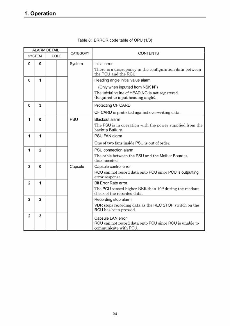
Table 8: ERROR code table of OPU (1/3)
ALARM DETAIL SYSTEM CODE
CATEGORY CONTENTS
0 0 Initial error There is a discrepancy in the configuration data between the PCU and the RCU.
0 1
System
Heading angle initial value alarm
(Only when inputted from NSK I/F) The initial value of HEADING is not registered. (Required to input heading angle).
0 3 Protecting CF CARD
CF CARD is protected against overwriting data. 1 0 Blackout alarm
The PSU is in operation with the power supplied from the backup Battery.
1 1 PSU FAN alarm
One of two fans inside PSU is out of order. 1 2
PSU
PSU connection alarm The cable between the PSU and the Mother Board is disconnected.
2 0 Capsule control error RCU can not record data onto PCU since PCU is outputting error response.
2 1 Bit Error Rate error The PCU sensed higher BER than 10-8 during the readout check of the recorded data.
2 2 Recording stop alarm VDR stops recording data as the REC STOP switch on the RCU has been pressed.
2 3
Capsule
Capsule LAN error RCU can not record data onto PCU since RCU is unable to communicate with PCU.
1. Operation
25
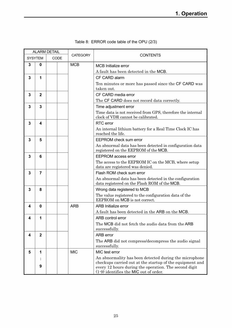
Table 8: ERROR code table of the OPU (2/3)
ALARM DETAIL SYSYTEM CODE
CATEGORY CONTENTS
3 0 MCB Initialize error A fault has been detected in the MCB.
3 1 CF CARD alarm Ten minutes or more has passed since the CF CARD was taken out.
3 2
MCB
CF CARD media error The CF CARD does not record data correctly.
3 3 Time adjustment error Time data is not received from GPS, therefore the internal clock of VDR cannot be calibrated.
3 4 RTC error An internal lithium battery for a Real Time Clock IC has reached the life.
3 5 EEPROM check sum error An abnormal data has been detected in configuration data registered on the EEPROM of the MCB.
3 6 EEPROM access error The access to the EEPROM IC on the MCB, where setup data are registered was denied.
3 7 Flash ROM check sum error An abnormal data has been detected in the configuration data registered on the Flash ROM of the MCB.
3 8
Wrong data registered to MCB The value registered to the configuration data of the EEPROM on MCB is not correct.
4 0 ARB Initialize error A fault has been detected in the ARB on the MCB.
4 1 ARB control error The MCB did not fetch the audio data from the ARB successfully.
4 2
ARB
ARB error The ARB did not compress/decompress the audio signal successfully.
5 1 : 9
MIC MIC test error An abnormality has been detected during the microphone checkups carried out at the startup of the equipment and every 12 hours during the operation. The second digit (1-9) identifies the MIC out of order.

1. Operation
26
Table 8: ERROR code table of the OPU (3/3) ALARM DETAIL
SYSYTEM CODE CATEGORY CONTENTS
6 0 * * Serial data (IEC61162-1/2 ) reception error The input received from the sensor is not normal. "**" identifies the sensor that has sent the unreadable data. Refer to table 9.
6 1 * *
Serial data
(NMEA)
Serial data (IEC61162-1/2 ) setup error The setup to receive NMEA serial data is not correct. "**" identifies the equipment. Refer to table 9.
7 0 FGB CH1 Radar image data error The FGB does not receive RGB signals from Radar connected to CH1.
7 1 CH2 Radar image data error The FGB does not receive RGB signals from Radar connected to CH2.
7 2 FGB Communication error The MCB does not communicate with the FGB normally via LAN.
7 3 FGB Setup data reception error The MCB does not receive the setup data of FGB successfully.
7 4 FGB Control error The MCB did not communicate with FGB successfully.
7 5 FAN alarm of NWP-46 FAN built in NWP-46 (Radar Interface Unit) is out of order.
7 6 FGB Real time monitor data transmission error The IP address for transmitting image data is not registered in the FGB yet.
8 0 RMB RMB communication error The MCB does not communicate with the RMB normally via LAN.
8 1 RMB Control error The MCB did not communicate with RMB successfully.
1. Operation
27
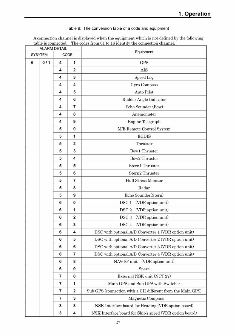
Table 9: The conversion table of a code and equipment
A connection channel is displayed when the equipment which is not defined by the following table is connected. The codes from 01 to 16 identify the connection channel.
ALARM DETAIL SYSYTEM CODE
Equipment
6 0 / 1 4 1 GPS 4 2 AIS 4 3 Speed Log 4 4 Gyro Compass 4 5 Auto Pilot 4 6 Rudder Angle Indicator 4 7 Echo Sounder (Bow) 4 8 Anemometer 4 9 Engine Telegraph 5 0 M/E Remote Control System 5 1 ECDIS 5 2 Thruster 5 3 Bow1 Thruster 5 4 Bow2 Thruster 5 5 Stern1 Thruster 5 6 Stern2 Thruster 5 7 Hull Stress Monitor 5 8 Radar 5 9 Echo Sounder(Stern) 6 0 DSC 1 (VDR option unit) 6 1 DSC 2 (VDR option unit) 6 2 DSC 3 (VDR option unit) 6 3 DSC 4 (VDR option unit) 6 4 DSC with optional A/D Converter 1 (VDR option unit) 6 5 DSC with optional A/D Converter 2 (VDR option unit) 6 6 DSC with optional A/D Converter 3 (VDR option unit) 6 7 DSC with optional A/D Converter 4 (VDR option unit) 6 8 NAV-I/F unit (VDR option unit) 6 9 Spare 7 0 External NSK unit (NCT-27) 7 1 Main GPS and Sub GPS with Switcher 7 2 Sub GPS (connection with a CH different from the Main GPS) 7 3 Magnetic Compass 3 3 NSK Interface board for Heading (VDR option board) 3 4 NSK Interface board for Ship’s speed (VDR option board)
1. Operation
28
1.6.3 How to operate the Operation Panel Unit (on NSK mode)
The NSK mode is usable only when the option NSK-I/F Board is installed in the RCU. The board is needed to receive ship’s heading angle either in Synchro or in step mode or to input log speed in pulse. When the NSK-I/F Board is not activated, the OPU is not operated in NSK mode.
1. Establish the initial value of HEADING: 1) Turn on the RECORDING CONTROL UNIT. 2) The alarm buzzer sounds as the initial HEADING angle has not been registered. 3) ALARM LED and the four digit ERROR CODE LEDs (“01__ “and “6033”) blink. 4) Press the ALARM ACK switch until the buzzer stops. 5) Press the MODE switch, and the OPU is operated in NSK mode. 6) The HEADING LED blinks until the initial value will be registered. 7) Confirm the HEADING angle displayed on ship’s Gyro. 8) Enter the value to the OPU.
• The blinking digit accepts input. Select the digit with RIGHT/LEFT switch. • Adjust the input value by UP/DOWN switch. • Repeat above procedure until the HEADING angle is inputted successfully.
9) Press the ENTER switch, and the initial value of HEADING is registered into the VDR. 10) The HEADING LED lights up. 11) The four digit LED repeats the heading angle shown on ship’s Gyro.
2. Return to the Normal mode from the NSK mode:
To return to the normal mode follow the next procedure. • Press the MODE switch. • The Mode automatically returns back to Normal mode in five minutes.

29
2. Specification
2.1 Protective Capsule Unit: PCU (NDH-316A/316)
(1) Function: The PCU is not a float-free model but a fixed type. The PCU records navigation data, hull data, conversation in the bridge, conversation over VHF radio, and radar image data to the recording medium in the PCU. When submerged, the Underwater Acoustic Beacon with PCU, which is battery-powered, transmits pulsed acoustic signal for capsule searchers.
(2) Performance: a) Interface:
1) Standard: IEEE802.3 (10Base-T/ 100Base-TX) 2) Protocol: TCP/IP
b) Recording duration and capacity: 1) Duration: 12 hours 2) Capacity: 2.0GB (flash memory)
c) Data Recording Interval: 1) Sensor Data: depends on the input from the sensors (normally 1 second)2) Audio Data: continuous (1 audio file / minute) 3) Image Data: 1 image per 15 second
d) Acoustic underwater beacon: 1) Operating frequency: 37.5kHz ±1kHz 2) Operating time: minimum 30 days after submerged in the water 3) Detectable range: 1800m - 3600m (depends on surrounding environment) 4) Battery life: maximum 5-years
(3) Environmental condition
There shall be neither the damage of the final record media nor the loss of recorded data under the conditions shown below. a) Shock: A half sine-wave pulse of 50G, with an interval of 11msecb) Penetration: A mass of 250 kg with a pin of 100mm diameter, dropped
from 3m c) Fire: 10 hours with 260 °C fire
1 hour with 1100 °C fire d) Deep-sea water pressure: 60 Mpa (equivalent to 6000m of depth) General environmental condition a) Operating temperature: -25°C to +55°C (IEC 60945 exposed type) b) Storage temperature -55°C to +70°C (IEC 60945 exposed type) c)Vibration: 2Hz to 13.2Hz ±1.0mm
13.2Hz to 100Hz 0.7G (4) General specification
a) Input voltage range: 19.5 - 36.5VDC b) Power consumption: 3W c) Dimensions: NDH-316A 186(W) x 209(D) x 217(H) mm
NDH-316 182(W) x 206(D) x 218(H) mm d) Mass: NDH-316A 7.9kg
NDH-316 8.7kg e) Color: fluorescent orange
2. Specification
30
2.2 Recording Control Unit: RCU (NDV-1800)
2.2.1 Operation panel (Internal)
(1) Performance: a) Button operation:
1) Recording stop: Stop to record data to PCU 2) Recording restart: Restart to record data to PCU 3) CF Card recording stop: Stop to record data to CF card.
(enables to take out CF card from RCU) 4) Protecting CF Card: Protecting recorded data on CF card against
overwriting and releasing protection of CF card b) LED Indication:
1) Recording status Recording / Recording stop 2) CF card status Recording / Recording stop (enables to eject CF card)
/ Protecting 3) CF card Media alarm Access error to CF card
2.2.2 Data Processor Unit
(1) Function: a) Control of recording navigation and hull data to PCU. b) Collects data of navigation and hull condition according to IEC61162-1/2.
The data collected are as follows according to the IEC61996 4.6 (IMO A.861 5.4). 1) Date and Time (UTC) 2) Ship’s position measured by the electronic position fixing system 3) Ship’s speed (over ground/water) 4) Ship’s heading with a gyrocompass or magnetic compass 5) Under keel clearance 6) Main alarms (indicated in the bridge) 7) Rudder order and response data 8) Engine order and response data 9) Hull opening status (for RO-RO passenger ships and ferry ships only) 10) Watertight door / Fire door status 11) Bow acceleration and hull stress data
(only for the ships mandatorily having hull stress indicator) 12) Wind direction / wind speed data
(only when the vessel is equipped with anemometer) c) Capturing, encoding and recording of conversation audio on the bridge, VHF
communications audio and radar image shown on the display d) Copying recorded data to CF card for backup and protecting the recorded data on CF
CARD e) Monitoring and control of the system
2. Specification
31
(2) Performance:
a) Communication to PCU: 1) Standard: IEEE802.3 (10Base-T/ 100Base-TX ) 2) Protocol: TCP/IP
b) Sensor data input : 1) Input channel: up to 32 (channels) 2) Data input interface: IEC61162-1/-2 (RS-422) 3) Recording interval: depends on the input from the sensors (normally 1 second)
c) Bridge audio input: 1) Input channel: up to 9 (channels) 2) Input sensitivity: 6kHz 3) Recording interval: continuous (1 audio file / minute)
d) VHF communications input (audio): 1) Input channel: up to 3 (channels) 2) Input sensitivity: 3.5kHz 3) Input level: 0 dBm 600-ohm balance 4) Recording interval: continuous (1 audio file / minute)
e) Radar image data input (input of No1. X band radar is recommended): 1) Input channel: 2 (channels)
Auto selection of a radar image from both channels (If the radar is of JRC make, automatic selection of in-operation radar is possible.) * Refer to the clause 2.2.8 for details.
2) Input interface: analog RGB/Hs/Vs - RGB: 0.7Vp-p (video signal) - Hs: TTL - Vs: TTL
3) Resolution: 640 x 350 – 1600 x 1200 pixel (conforms to VESA DMTS)
4) Refresh rate: 60 - 85 Hz (conforms to VESA DMTS) (Resolution 1600 x 1200 pixel 60Hz only)
5) Recording interval: 1 image every 15 seconds f) Recording data backup:
1) Media: CF card (Adapter for PCMCIA type-2 is attached to the RCU.)
2) Storage capacity: 2.0GB g) Blackout processing: 1) Recording duration: 2 hours while blackout (during the blackout, only the conversation in the
bridge is recorded) 2) Restoration time required: less than 1 minute (Recovery time from blackout operation to normal
operation on restoration of ship’s mains.) h) GPS select signal input:
1) Interface: Dry (voltage free) contact closure (Commonly used with External Contact Input )
2) Operation: Recording GPS selection (active open/close) i) RADAR select signal input: (So far only JMA-9900, JMA-900M, JMA-5300 supply
this signal) 1) Interface of JRC radar: IEC61162-1 (RS-422) 2) Operation of JRC radar: Active radar selection by JRC original sentence

2. Specification
32
3) Interface with other radar: Dry (voltage free) contact closure (Commonly used with External Contact Input )
4) Operation of other radar: Recording RADAR selection by dry contact closure (active open/close)
j) External Contact Input (dry contact): 1) Number of input: maximum 3 dry contacts (voltage free)
(Commonly used with the input signals which select RADAR or GPS.)
2) Output sentences: Registers sentences at the time of their making and opening
2.2.3 Power Supply Unit: PSU
(1) Function: a) Power supply to RCU and PCU in normal operation b) Power supply to RCU and PCU for 2 hours on blackout.
(2) Performance:
a) Input voltage range: 100 - 120VAC +/- 10% 1-phase 50/60Hz +/-5% 200 - 240VAC +/- 10% 1-phase 50/60Hz +/-5% (Auto switching)
b) Output voltage: 5VDC, 12VDC, 24VDC c) Maximum power output: 140VA d) Battery capacity: 24VDC 5Ah e) Expectant battery age: max 4-years
(Depending on circumstance. This age is based on ambient operating temperature: 25 deg., load 70%)
2.2.4 External interface
a) External alarm lamp output: 1) Interface: Dry (voltage free) contact closure 2) Operation: System down (normal-close or open) 3) Current: 1A or less at 24VDC / 0.5A or less at 125VAC
b) External alarm buzzer output: 1) Interface: Dry (voltage free) contact closure 2) Operation: System down (normal-close or open) 3) Current: 1A or less at 24VDC / 0.5A or less at 125VAC
2.2.5 Environmental condition
(1) Operating temperature: -15°C to +55°C (IEC 60945 protected type) (2) Temperature and humidity: +40°C, 93% (3) Vibration: 2Hz to 13.2Hz ±1.0mm
13.2Hz to 100Hz 0.7G
2. Specification
33
2.2.6 General specification
(1) Power voltage: 100 - 120VAC +/- 10% 1-phase 50/60Hz (IEC 60945) 200 - 240VAC +/- 10% 1-phase 50/60Hz (IEC 60945)
(2) Power consumption: (including capsule unit & operation panel unit & microphone phantom power)
90VA in UPS battery charge 50VA in normal operation
(3) Dimensions: 419.5(w) x 250(d) x 480(h) mm (4) Mass: 23.0kg (5) Color: N7 semi-gloss texture
2.2.7 NSK interface (Option)
(1) Function: Records gyro compass signal (Synchro / Step) and/or Ship’s speed log signal as IEC61162-1 sentence formatter
(2) Performance: a) Signal input: Synchro signal for Gyro compass
Ratio: 360X, 180X, 90X, 36X, 1X Primary voltage: AC50 – 115V, 50/60Hz Secondary voltage: AC20 – 90V, 50/60Hz
Step signal for Gyro compass Ratio: 360X, 180X, 90X, 36X, 1X Voltage: DC24V / 35V / 50V / 70V
Pulse signal for speed log Pulse number: 200P / 400P / 100P / 160P (Per NM)Interface: Opto-Isolation / dry contact signal
b) Recoding data:
Data type: IEC61162-1 Heading Sentence formatter: HDT Sip speed Sentence formatter: VBW
2.2.8 Radar switching recording function The specification of radar switching recording function when connecting two radars is as follows:
(1) Function: a) The radar screen in operation is automatically identified and recorded.
Automatic identification can be performed by monitoring the operation conditions of the scanners, which can be judged by the original sentences conforming to IEC61162 outputted from JRC radars.
b)Switching recording function is available only when JRC radars are connected. The radars that have this switching recording function are the current models (JMA-5300, JMA-9900, JMA-900M) or new. The older models do not work as such.
(2) Performance:
Radar switching recording function supports for connecting two non-JRC radars ( refer to b) and c) below ). However, for non-JRC radars, we do not recommend
2. Specification
34
using switching recording function because automatic identification of the working radar is not functional under the normal operation conditions. For using switching recording function in the case of non-JRC radars, read the following specification for proper recording of the working radar images.
a) Current JRC radars (JMA-5300, JMA-9900, JMA-900M) Operation conditions of scanners are monitored by the sentences conforming to IEC61162 outputted from X-band radars. When the scanner of X-band radar is in operation, the radar image connecting to CH1 will be recorded. When the scanner of X-band radar is not in operation, the radar image connecting to CH2 will be recorded.
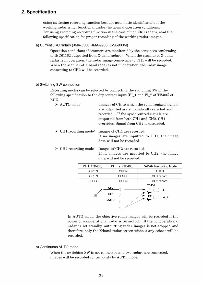
b) Switching SW connection Recording modes can be selected by connecting the switching SW of the following specification to the dry contact input (PI_1 and PI_2 of TB406) of RCU.
AUTO mode: Images of CH to which the synchronized signals are outputted are automatically selected and recorded. If the synchronized signals are outputted from both CH1 and CH2, CH1 overrides. Signal from CH2 is discarded.
CH1 recording mode: Images of CH1 are recorded. If no images are inputted to CH1, the image data will not be recorded.
CH2 recording mode: Images of CH2 are recorded. If no images are inputted to CH2, the image
data will not be recorded.
PI_1(TB406) PI_ 2(TB406) RADAR Recording Mode OPEN OPEN AUTO OPEN CLOSE CH1 record CLOSE OPEN CH2 record
In AUTO mode, the objective radar images will be recorded if the power of nonoperational radar is turned off. If the nonoperational radar is set standby, outputting radar images is not stopped and therefore, only the X-band radar screen without any echoes will be recorded.
c) Continuous AUTO mode When the switching SW is not connected and two radars are connected, images will be recorded continuously by AUTO mode.

2. Specification
35
2.3 Operation Panel Unit: OPU (NCG-169)
(1) Function: Visible indication and audible alarm for VDR system alarm in the Wheelhouse Display of the cause of an error Input of Heading initial value
(2) Performance: a) Type: Flush mount type or Wall mount type b) Power supply: Supplied from the RCU NDV-1800 c) Indication: LED lighting for alarm indication
4 digit LED for error code indication Buzzer (mutable by ACK switch)
d) Operation: Alarm acknowledgement Dimmer of LED
(3) NSK operation: (Optional NSK interface board is needed in the RCU.) a) Operation Entry of the initial value of heading b) Indication Heading value indication (4) Environmental condition:
a) Operating temperature: -15 deg. to +55 deg. (IEC 60945 protected type) b) Temperature and humidity: +40°C, 93% c) Vibration: 2Hz to 13.2Hz ±1.0mm
13.2Hz to 100Hz 0.7G (5) General specification
a) Dimensions: 145(w) x 50(d) x 165(h) mm b) Mass: 0.3kg c) Color: N4 semi-gloss texture
2.4 Microphone Unit (NVT-161)
(1) Function: Acquisition of W/H conversation, Alarms and sounds etc. in W/H
(2) Performance: a) Type: Ceiling mount type, wall mount type b) Device: Electoret condenser microphone c) Directivity: Hemispherically omnidirectional d) Receiving range: 2.5m of radius e) Power supply: Phantom powered by 12VDC f) Test device: Built-in speaker for audio acquisition test
(3) Environmental condition: a) Operating temperature: -15°C to +55°C (IEC 60945 protected type) b) Temperature and humidity: +40°C, 93% c) Vibration: 2Hz to 13.2Hz ±1.0mm
13.2Hz to 100Hz 0.7G (4) General specification
a) Dimensions: 110(w) x 44.5(d) x 160(h) mm b) Mass: 0.2kg c) Color: N4 semi-gloss texture
2. Specification
36
2.5 Connection Box (NQE-3163)
(1) Function: Waterproofed type junction box which connects RCU with a PCU.
(2) Performance: a) Connection device: Built-in terminal blocks
(3) Environmental condition: a) Operating temperature: -25 deg. to +55 deg. (IEC 60945 exposed type) b) Temperature and humidity: +40°C, 93% c) Vibration: 2Hz to 13.2Hz ±1.0mm
13.2Hz to 100Hz 0.7G d) Waterproof grade: IPx6
(4) General specification a) Dimensions: 170(w) x 176(d) x 87(h) mm b) Mass: 1.3kg c) Color: 7.5BG 7/2
2.6 Waterproof Microphone Unit (NVT-162)
(1) Function: Acquisition of wing conversation etc. (2) Performance:
a) Type: Wall mount type b) Device: Electoret condenser microphone c) Directivity: Hemispherically omnidirectional d) Receiving range: 2.5m of radius e) Power supply: Phantom powered by 12VDC f) Test device: Built-in speaker for audio acquisition test
(3) Environmental condition: a) Operating temperature: -25°C to +55°C (IEC 60945 exposed type) b) Temperature and humidity: +40°C, 93% c) Vibration: 2Hz to 13.2Hz ±1.0mm
13.2Hz to 100Hz 0.7G d) Waterproof grade: IPx6
(4) General specification a) Dimensions: 126(w) x 93(d) x 110(h) mm b) Mass: 1.2kg c) Color: N7 semi-gloss
2.7 Digital Signal Converter (NCT-72) 64CH -Option-
(1) Function: Acquisition of alarms or status condition via dry contact closure.
(2) Performance: a) Dry contact Input port: Dry (voltage free) contact closure
Max. 64 port
2. Specification
37
b) Contact closure interface: 1) Driving power supply: +12VDC 2) Status: Normal open / Normal close
c) Communication port To the NDV-1800 RCU d) Data output interface Data type: IEC61162-1
(3) Optional Analog interface: (Optional Analog signal converting board CEF-60 is needed in DSC NCT-63.)
a) Analog signal Input port: Max. 8 port b) Signal input:
1) Voltage: +/-500mV, +/-5V, +/-10V 2) Current: +/-20mA
c) Communication port Same port as dry contact signals d) Data output interface Data type: IEC61162-1
Analog Sentence formatter: XDR (4) Environmental condition:
a) Operating temperature: -15 deg. to +55 deg. (IEC 60945 protected type) b) Temperature and humidity: +40°C, 93% c) Vibration: 2Hz to 13.2Hz ±1.0mm
13.2Hz to 100Hz 0.7G (5) General specification
a) Power voltage: 100 - 120Vac +/- 10% 1-phase 50/60Hz (IEC 60945) 200 - 240Vac +/- 10% 1-phase 50/60Hz (IEC 60945)
b) Power consumption: 25VA c) Dimensions: 300(w) x 130(d) x 420(h) mm d) Mass: 5kg e) Color: N7 semi-gloss
2.8 Digital Signal Converter (NCT-63) 16CH -Option-
(1) Function: Acquisition of alarms or status condition via dry contact closure.
(2) Performance: a) Dry contact Input port: Dry (voltage free) contact closure
Max. 16 port b) Contact closure interface:
1) Driving power supply: +12VDC 2) Status: Normal Close / Normal open
c) Communication port To the NDV-1800 RCU d) Data output interface Data type: IEC61162-1
(3) Optional Analog interface: (Optional Analog signal converting board CEF-60 is needed.)
a) Analog signal Input port: Max. 8 port b) Signal input:
1) Voltage: +/-500mV +/-5V +/-10V 2) Current: +/-20mA
c) Communication port Same port as dry contact signals d) Data output interface Data type: IEC61162-1
Analog Sentence formatter: XDR

2. Specification
38
(4) Environmental condition:
a) Operating temperature: -15 deg. to +55 deg. (IEC 60945 protected type) b) Temperature and humidity: +40°C, 93% c) Vibration: 2Hz to 13.2Hz ±1.0mm
13.2Hz to 100Hz 0.7G (5) General specification
a) Power voltage: 100 - 120Vac +/- 10% 1-phase 50/60Hz (IEC 60945) 200 - 240Vac +/- 10% 1-phase 50/60Hz (IEC 60945)
b) Power consumption: 25VA c) Dimensions: 300(w) x 130(d) x 230(h) mm d) Mass: 2.9kg e) Color: N7 semi-gloss
2.9 Radar Interface Unit (NWP-46) -Option-
(1) Function: The NWP-46 is required when a high resolution (UXGA) radar display is connected to the VDR. The NWP-46 is an option unit in order to install a FGB near the radar, because high resolution RGB signals can not be extended to the VDR, The Frame Grabber Board (FGB) in the NWP-46 is moved from the RCU.
(2) Performance: a) Basic performance: The same as the Radar image input specification of the
RCU. b) Communication port To the NDV-1800 RCU via Ethernet
(3) Environmental condition: a) Operating temperature: -15 deg. to +55 deg. (IEC 60945 protected type) b) Temperature and humidity: +40°C, 93% c) Vibration: 2Hz to 13.2Hz ±1.0mm
13.2Hz to 100Hz 0.7G (4) General specification
a) Power voltage: 100 - 120Vac +/- 10% 1-phase 50/60Hz (IEC 60945) 200 - 240Vac +/- 10% 1-phase 50/60Hz (IEC 60945)
b) Power consumption: 10VA c) Dimensions: 255(w) x 160(d) x 72(h) mm d) Mass: 1.5kg e) Color: N4 semi-gloss
2. Specification
39
2.10 General Environmental Condition of Use
2.10.1 Condition of Use
a) Vessels required to carry VDR:
Mercantile vessels of 3,000G/T or more that are engaged in international voyage
Passenger vessels of 150G/T or more that are engaged in international voyage
b) Unit installation locations:
1) The Protective Capsule Unit: External deck above bridge 2) The Connection Box: External deck above bridge 3) The Recording Control Unit: Bridge (or electric room) 4) The Operation Panel Unit: Navigation space in the Bridge 5) The Microphone Unit: Ceiling or bulkhead 6) The Waterproof Microphone Unit: Wings 7) The Digital Signal Converter: Bridge (or electric room) 8) The Radar Interface Unit: near the Radar
c) Installation methods:
1) The Protective Capsule Unit: Mounted on the deck 2) The Connection Box: Mounted on the deck 3) The Recording Control Unit: Hung on the bulkhead 4) The Operation Panel Unit: Hung on the bulkhead or flash
mount on the Console 5) The Microphone Unit: Flash mount on the Ceiling or hung
on the bulkhead 6) The Waterproof Microphone Unit: Hung on the bulkhead 7) The Digital Signal Converter: Hung on the bulkhead 8) The Radar Interface Unit: Mounted on the Radar
2.10.2 Power Supply Environment Conditions
a) AC power supply input range:
1) AC100/110/115/120V ±10% 2) AC200/220/240V ±10%
b) AC power supply frequency fluctuation range:
1) 50Hz ±5% 2) 60Hz ±5%

2. Specification
40
2.10.3 Environmental Condition
a) Exposed type equipment
(Protective Capsule Unit, Waterproof Microphone Unit)
1) Operation temperature range: -25°C to +55°C 2) Storage temperature: -25°C to +70°C 3) Temperature and humidity: +40°C, 93%
4) Vibration: 2Hz to 13.2Hz ±1.0mm 13.2Hz to 100Hz 0.7G
b) Protected type equipment
(Recording Control Unit, Operation Panel Unit, Microphone Unit, Option Unit)
1) Operation temperature range: -15°C to +55°C 2) Temperature and humidity: +40°C, 93%
3) Vibration: 2Hz to 13.2Hz ±1.0mm 13.2Hz to 100Hz 0.7G
41
Do not attempt checking or repairs on the internal part of the equipment by yourself.
Checking or repairs by anyone other than our professional maintainer may result in a fire or an electric shock.
Ask for checking or repairs of the inside of the equipment to the Sales Department, the nearest branch company, a branch office, a sales office, or any agent of Japan Radio Co., Ltd.
3. Maintenance and Inspection
CAUTION
Do not use organic solvent such as thinner and benzine to clean the surface. These agents damage the surface coating.
Be sure to remove dirt and dust, if any, from the surface and wipe it with a clean dry cloth.
3.1 Daily Maintenance
The life of the equipment depends greatly on the quality of maintenance. To keep the JCY-1800 in the best operating condition, perform inspections of the equipment regularly. By the inspection, problems can be identified before they develop into major malfunctions.
3.1.1 Cleaning
CAUTION
If the equipment is splashed with seawater or fresh water, wipe it dry immediately. Ignoring the caution may result in failures or operational malfunctions.
To remove stains from the equipment, gently wipe it with a soft cloth lightly impregnated with neutral detergent.
3.1.2 Check of the expiry date of the battery
Check the expiry date of the RCU battery and the underwater acoustic beacon that is fixed above the capsule. If the expiration is approaching, contact the Sales Department, the nearest branch company, branch office, sales office, or any agent of Japan Radio Co., Ltd.
WARNING

3. Maintenance and Inspection
42
3.2 Periodic Inspection
Periodic internal check is recommended on the equipment and on its connections with the PSU and the other devices. This check is charged. Annual maintenance is requested by the Ship Class, please contact the Sales Department, the nearest branch company, a branch office, a sales office, or any agent of Japan Radio Co., Ltd.
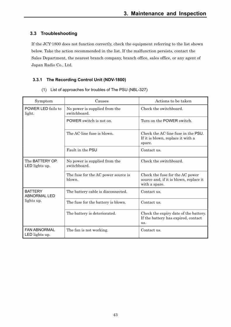
3. Maintenance and Inspection
43
3.3 Troubleshooting
If the JCY-1800 does not function correctly, check the equipment referring to the list shown below. Take the action recommended in the list. If the malfunction persists, contact the Sales Department, the nearest branch company, branch office, sales office, or any agent of Japan Radio Co., Ltd.
3.3.1 The Recording Control Unit (NDV-1800)
(1) List of approaches for troubles of The PSU (NBL-327)
Symptom Causes Actions to be taken
No power is supplied from the switchboard.
Check the switchboard.
POWER switch is not on. Turn on the POWER switch.
The AC-line fuse is blown. Check the AC-line fuse in the PSU. If it is blown, replace it with a spare.
POWER LED fails to light.
Fault in the PSU Contact us.
No power is supplied from the switchboard.
Check the switchboard. The BATTERY OP. LED lights up.
The fuse for the AC power source is blown.
Check the fuse for the AC power source and, if it is blown, replace it with a spare.
The battery cable is disconnected. Contact us.
The fuse for the battery is blown. Contact us.
BATTERY ABNORMAL LED lights up.
The battery is deteriorated. Check the expiry date of the battery. If the battery has expired, contact us.
FAN ABNORMAL LED lights up.
The fan is not working. Contact us.

3. Maintenance and Inspection
44
(2) List of approaches for troubles of The Data Processor Unit (NDL-46)
Symptom Causes Actions to be taken
The RCU is off. The power is not supplied to the PCU.
Check the switchboard. Turn on the PSU.
The recording of data into the PCU has been stopped manually.
Press the REC START switch on the MCB to restart the recording of data.
Faulty wiring between the RCU and the PCU
Check the hookups in the Connection Box.
REC LED fails to light.
Fault in the RCU Fault in the PCU
Reboot the RCU and see if it works normally. If it doesn’t, contact us.
The CARD STOP switch is left on. Press the CF CARD EJECT BUTTON and remove the card from the MCB. Then put it back again.
No CF CARD is loaded. Insert a CF CARD into the CARD slot of the MCB.
CARD LED fails to light up.
Fault in the RCU Reboot the RCU and see if it works normally. If it does not work, contact us.
Fault in the CF CARD Press the CF CARD EJECT BUTTON and remove it from the MCB. Then put it back again.
Fault in the RCU Reboot the RCU and see if it works normally. If it does not work, contact us.
MEDIA LED blinks.
No CF CARD is loaded. Insert a CF CARD into the CARD slot of the MCB.
CARD LED and MEDIA LED flashes.
The recorded data on CF CARD are protected against overwriting data.
It is normal operation since the recorded data in accident are protected against unauthorized or inadvertent overwriting. In the following cases, release the protection of CF CRAD to start recording data onto CF CARD. • It becomes unnecessary to preserve recorded data in accident after transferring preserved data to relevant authorities. • The recorded data in CF CARD have been protected by mistake.
Press REC START switch on MCB until CARD LED lights up (approx. 10 seconds).

3. Maintenance and Inspection
45
3.3.2 The Operation Panel Unit (NCG-169)
All failures of the RCU are indicated by the OPU as an error code.
Symptom Causes Actions to be taken
The software of the RCU freezes. Reboot the RCU. All LEDs blink and the alarm buzzer sounds. Faulty wiring between the RCU and
the OPU. Check the wiring between the RCU and the OPU.
The RCU is off. The power is not supplied to the PCU.
Check the switchboard. Turn on the PSU.
Stop manually the recording of data onto the PCU.
Press the REC START switch on the MCB in the RCU and restart the recording of data.
Faulty wiring between the RCU and the PCU
Check the hookups in the Connection Box.
RECORDING LED fails to light.
Fault in the RCU Fault in the PCU
Reboot the RCU and see if it works normally. If it doesn’t, contact us.
ERROR CODE: “01__” lights up.
Initial value of HEADING is not registered yet.
Enter the initial value of HEADING
ERROR CODE: “03__” lights up.
The recorded data on CF CARD are protected against overwriting data.
It is normal operation since the recorded data in accident are protected against unauthorized or inadvertent overwriting. In the following cases, release the protection of CF CRAD to start recording data onto CF CARD. • It becomes unnecessary to preserve recorded data in accident after transferring preserved data to relevant authorities. • The recorded data in CF CARD have been protected by mistake.
Press REC START switch on MCB until CARD LED lights up (approx. 10 seconds).
The CARD STOP switch is left on. Press the CF CARD EJECT BUTTON and remove it from the MCB. Then put it back again.
No CF CARD is loaded. Insert a CF CARD into the CARD slot of the MCB.
ERROR CODE: “31__” lights up.
Fault in the RCU Reboot the RCU and see if it works normally. If it doesn’t, contact us.
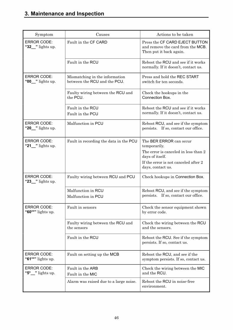
3. Maintenance and Inspection
46
Symptom Causes Actions to be taken
Fault in the CF CARD Press the CF CARD EJECT BUTTON and remove the card from the MCB. Then put it back again.
ERROR CODE: “32__” lights up.
Fault in the RCU Reboot the RCU and see if it works normally. If it doesn’t, contact us.
Mismatching in the information between the RCU and the PCU.
Press and hold the REC START switch for ten seconds.
Faulty wiring between the RCU and the PCU.
Check the hookups in the Connection Box.
ERROR CODE: “00__” lights up.
Fault in the RCU Fault in the PCU
Reboot the RCU and see if it works normally. If it doesn’t, contact us.
ERROR CODE: “20__” lights up.
Malfunction in PCU Reboot RCU, and see if the symptom persists. If so, contact our office.
ERROR CODE: “21__” lights up.
Fault in recording the data in the PCU The BER ERROR can occur temporarily. The error is canceled in less than 2 days of itself. If the error is not canceled after 2 days, contact us.
Faulty wiring between RCU and PCU Check hookups in Connection Box. ERROR CODE: “23__” lights up.
Malfunction in RCU Malfunction in PCU
Reboot RCU, and see if the symptom persists. If so, contact our office.
Fault in sensors Check the sensor equipment shown by error code.
Faulty wiring between the RCU and the sensors
Check the wiring between the RCU and the sensors.
ERROR CODE: “60**” lights up.
Fault in the RCU
Reboot the RCU. See if the symptom persists. If so, contact us.
ERROR CODE: “61**” lights up.
Fault on setting up the MCB Reboot the RCU, and see if the symptom persists. If so, contact us.
Fault in the ARB Fault in the MIC
Check the wiring between the MIC and the RCU.
ERROR CODE: “5*__” lights up.
Alarm was raised due to a large noise. Reboot the RCU in noise-free environment.

3. Maintenance and Inspection
47
Symptom Causes Actions to be taken
Power failure Check the power supply in the RCU.
No power is supplied from the switchboard.
Check the switchboard.
ERROR CODE: “10__” lights up.
The fuse for the AC power source is blown.
Check the fuse for the AC power source and, if it is blown, replace it with a spare.
ERROR CODE: “11__” lights up.
The fan of PSU is not working. Contact us.
ERROR CODE: “30__” / “35__” / “36__” / “37__” / “38__” light up.
Fault in the MCB Reboot the RCU, and see if the symptom persists. If so, contact us.
ERROR CODE: “33__” lights up.
GPS is faulty or setting error on the MCB
Check the GPS. If the GPS is error-free, contact us.
ERROR CODE: “34__” lights up.
An internal battery for a Real Time Clock IC has run out of the life.
Contact us for exchanging the battery.
ERROR CODE: “40__”/“41__”/ “42__” lights up.
Fault in the ARB Reboot the RCU, and see if the symptom persists or not. If yes, contact us.
ERROR CODE: “70__” / “71__” lights up.
Fault in RGB signals from a RADAR 70__: CH1 71__: CH2
Check the RADAR. If an image is displayed on the screen, check the wiring between the RADAR and the RCU.
Faulty wiring between the FGB and the MCB
Check the wiring between the FGB and the MCB.
ERROR CODE: “72__” lights up.
Fault in the FGB Fault in the MCB
Reboot the RCU, and see if the symptom persists or not. If yes, contact us.
ERROR CODE: “73__” / “76__” lights up.
Fault on setting up the FGB Reboot the RCU, and see if the symptom persists or not. If yes, contact us.
ERROR CODE: “74__” lights up.
Fault in the FGB
Reboot the RCU, and see if the symptom persists or not. If yes, contact us.
ERROR CODE: “75__” lights up.
The fan of NWP-46 is out of order. Contact us.
ERROR CODE: “12__” lights up.
Faulty wiring between the PSU and the MCB
Reboot the RCU, and see if the symptom persists or not. If yes, contact us.
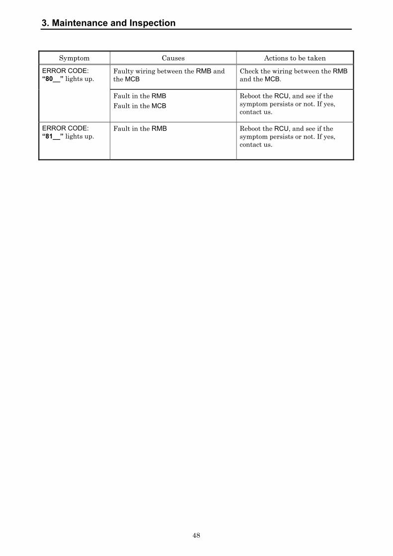
3. Maintenance and Inspection
48
Symptom Causes Actions to be taken
ERROR CODE: “80__” lights up.
Faulty wiring between the RMB and the MCB
Check the wiring between the RMB and the MCB.
Fault in the RMB Fault in the MCB
Reboot the RCU, and see if the symptom persists or not. If yes, contact us.
ERROR CODE: “81__” lights up.
Fault in the RMB Reboot the RCU, and see if the symptom persists or not. If yes, contact us.

49
4. After-sales Service
4.1 To request the service
If you suppose the product may be out of order, read section 3 and take the action recommended thereof. If the equipment will still be faulty, you are advised to stop the operation and contact the Sales Department, the nearest branch company, branch office, sales office, or any agent of Japan Radio Co., Ltd. immediately.
1) Repair within the warranty period
If any failure occurs on the product during the normal operation in accordance with the instruction manual, the dealer or JRC will carry out the repair free of charge. In case the trouble was caused by user’s misuse, faulty operation, negligence or force ma-jeure such as natural disaster and fire, the repair shall be charged.
2) Repair after the warranty period The service after the warranty period is Not Free. It is charged.
3) Let us know the Helpful information for service engineer a) Product name, model, manufacturing date and serial number b) Trouble conditions (Go into details as much as possible. Refer to “VDR
Failure Check List” in the next page) c) Name of shipping company/organization, address and telephone number
For further details of after-sales service, contact the JRC Offices in the list at the end of this manual.
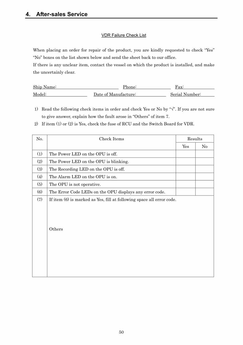
4. After-sales Service
50
VDR Failure Check List
When placing an order for repair of the product, you are kindly requested to check “Yes” “No” boxes on the list shown below and send the sheet back to our office. If there is any unclear item, contact the vessel on which the product is installed, and make the uncertainly clear. Ship Name: Phone: Fax: Model: Date of Manufacture: Serial Number: 1) Read the following check items in order and check Yes or No by “√”. If you are not sure
to give answer, explain how the fault arose in “Others” of item 7. 2) If item (1) or (2) is Yes, check the fuse of RCU and the Switch Board for VDR.
Results No. Check Items Yes No
(1) The Power LED on the OPU is off. (2) The Power LED on the OPU is blinking. (3) The Recording LED on the OPU is off. (4) The Alarm LED on the OPU is on. (5) The OPU is not operative. (6) The Error Code LEDs on the OPU displays any error code. (7) If item (6) is marked as Yes, fill at following space all error code.
Others

4. After-sales Service
51
4.2 Disposal of unit
When disposing of this unit, abide by the local laws and regulations. Contact the Sales Department, the nearest branch company, branch office, sales office, or any agent of Japan Radio Co., Ltd. and ask them to replace it without discarding the battery.
4.3 Disposal of used battery
Never short-circuit the + and – pins. Never disassemble, modify, destroy, throw into fire, heat, use with non-specified applications and use after the expiry date.
Above acts may cause leakage of fluid, generation of heat, fire, explosion, destruction, or injury by heat.
The RCU (NDV-1800) of this equipment incorporates a battery.
Used batteries are to be recycled. Regarding the replacement and recycle, contact the Sales Department, the nearest branch company, branch office, sales office, or any agent of Japan Radio Co., Ltd. and ask them the replacement and recycle.
The MCB (CDJ-2304), the RMB (CDK-287) and the Underwater Acoustic Beacon on the PCU of this equipment incorporate a lithium battery.
Used batteries are to be recycled. Regarding the replacement and recycle, contact the Sales Department, the nearest branch company, branch office, sales office, or any agent of Japan Radio Co., Ltd. and ask them the replacement and recycle.
4. After-sales Service
52
This page left blank intentionally
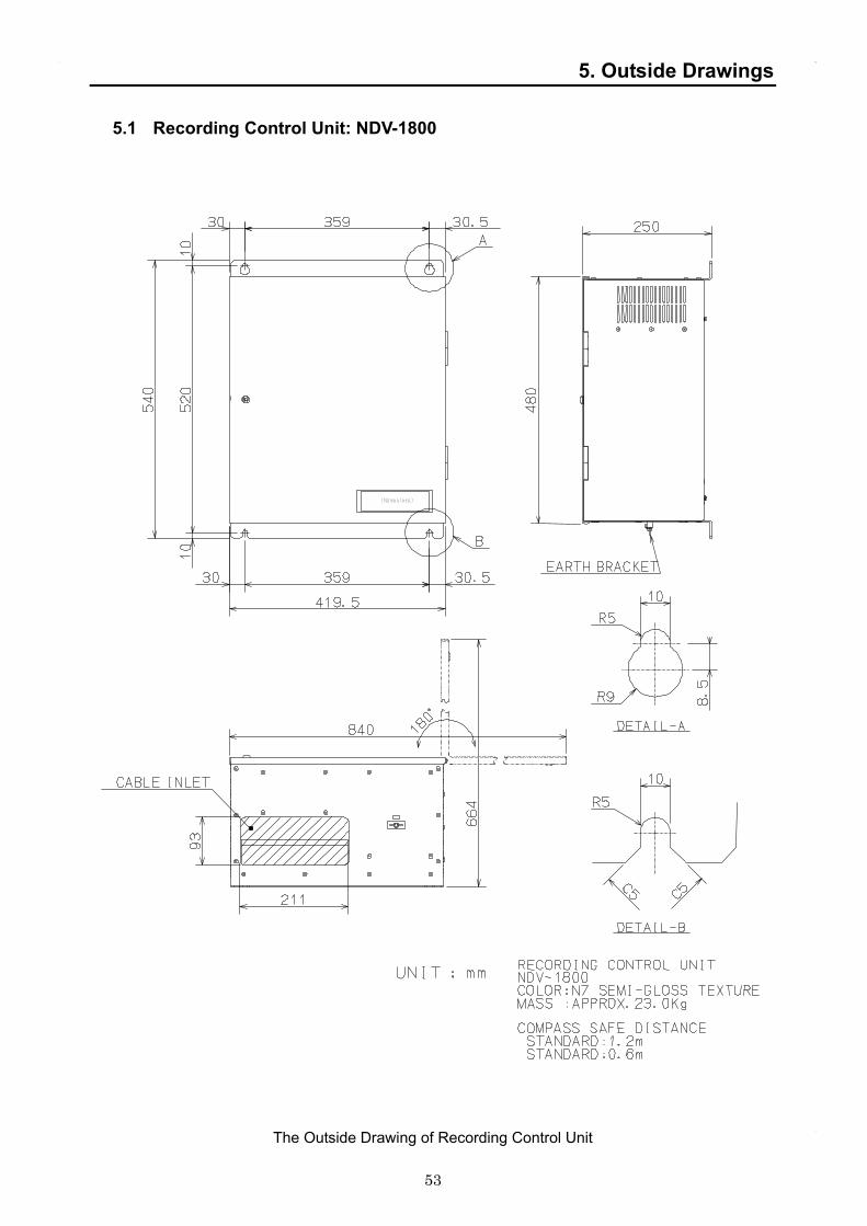
53
5. Outside Drawings
5.1 Recording Control Unit: NDV-1800
The Outside Drawing of Recording Control Unit

5. Outside Drawings
54
5.2 Operation Panel unit: NCG-169
The Outside Drawing of Operation Panel Unit
NCG-169 VDR OPERATION PANEL
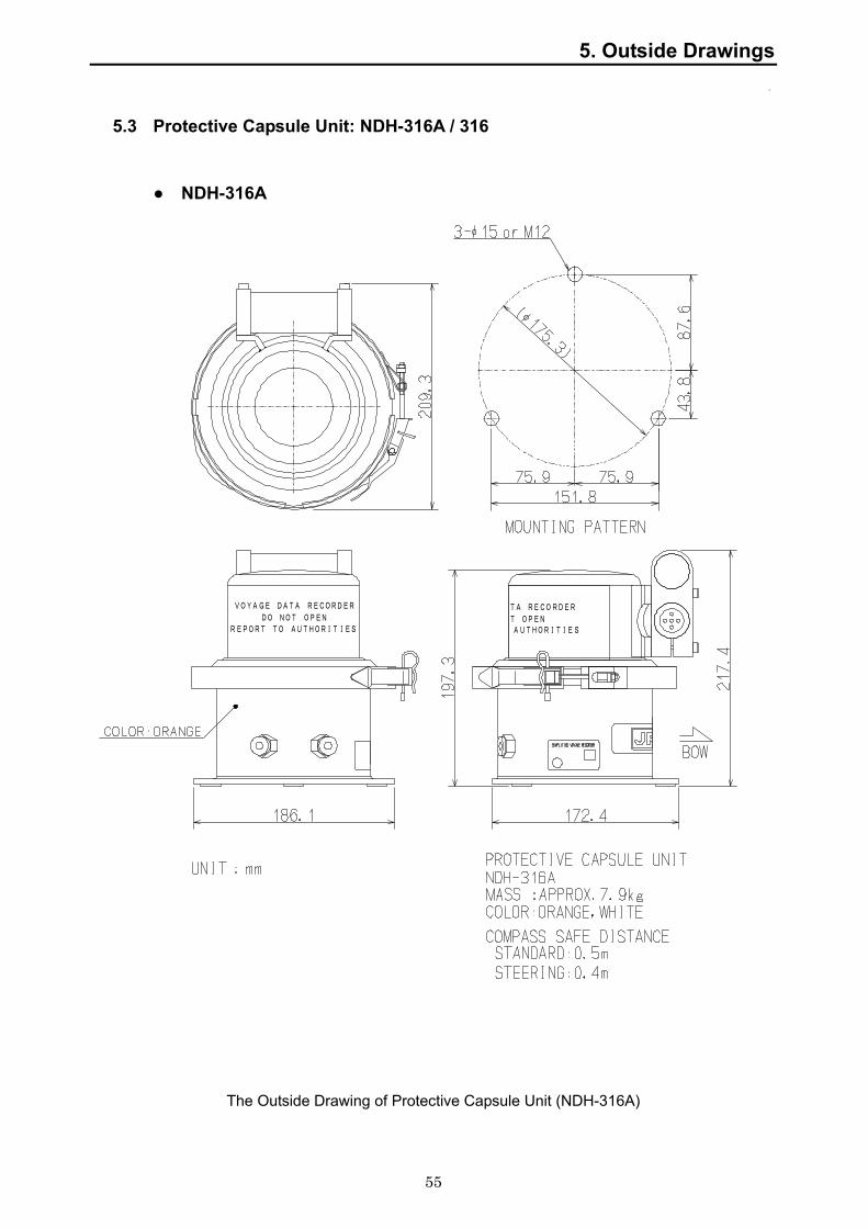
5. Outside Drawings
55
5.3 Protective Capsule Unit: NDH-316A / 316
● NDH-316A
The Outside Drawing of Protective Capsule Unit (NDH-316A)
AUTHORITIES
TA RECORDER
T OPEN
VOYAGE DATA RECORDER
DO NOT OPENREPORT TO AUTHORITIES

5. Outside Drawings
56
● NDH-316
The Outside Drawing of Protective Capsule Unit (NDH-316)
3L
AUTHORITIES
TA RECORDER
T OPEN
VOYAGE DATA RECORDER
DO NOT OPENREPORT TO AUTHORITIES

5. Outside Drawings
57
5.4 Connection Box: NQE-3163
The Outside Drawing of Connection Box
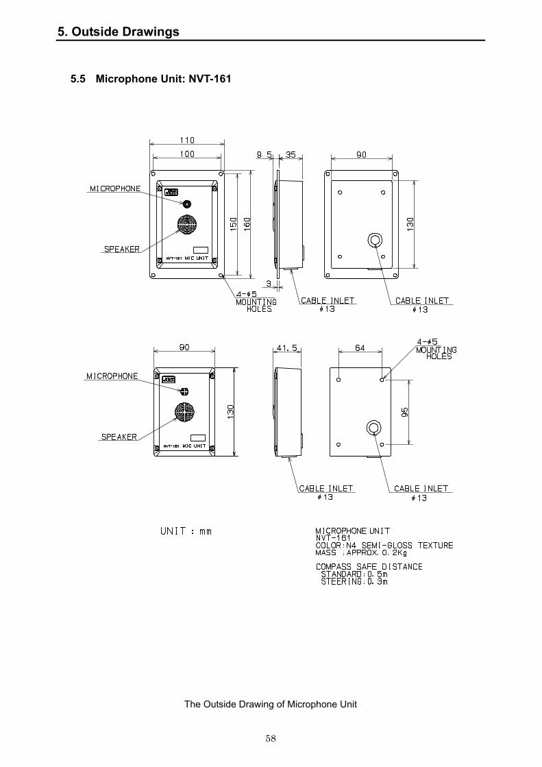
5. Outside Drawings
58
5.5 Microphone Unit: NVT-161
The Outside Drawing of Microphone Unit

5. Outside Drawings
59
5.6 Waterproof Microphone Unit: NVT-162
Option
The Outside Drawing of Waterproof Microphone Unit

5. Outside Drawings
60
5.7 Digital Signal Converter: NCT-72 (64ch)
Option
The Outside Drawing of Digital Signal Converter (64ch)
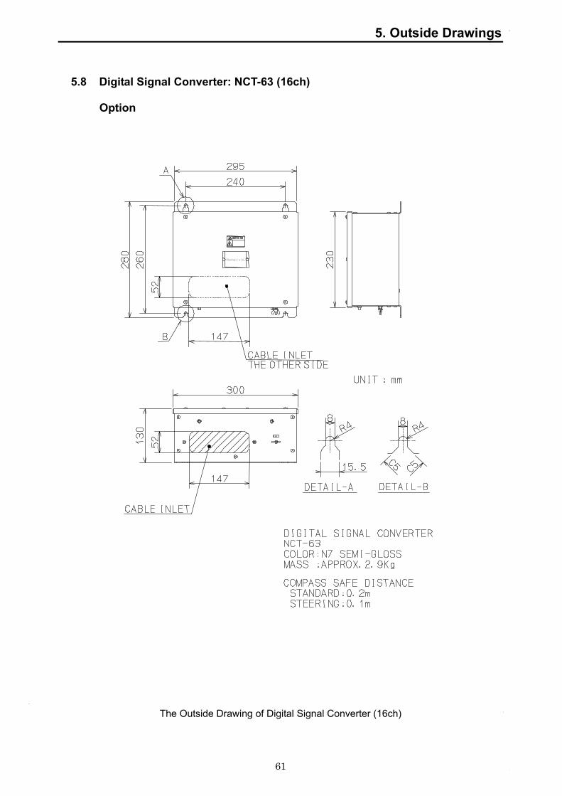
5. Outside Drawings
61
5.8 Digital Signal Converter: NCT-63 (16ch)
Option
The Outside Drawing of Digital Signal Converter (16ch)

5. Outside Drawings
62
5.9 Radar Interface Unit: NWP-46
Option
The Outside Drawing of Radar Interface Unit

5. Outside Drawings
63
This page left blank intentionally

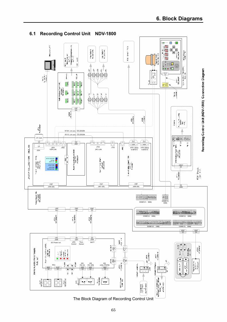
65
6. Block Diagrams
6.1 Recording Control Unit NDV-1800
The Block Diagram of Recording Control Unit
DC Power out
J308
BATTThrm. Sensor
(10)J307(8)
J306(2)
UPS Control
J310J309FAN
(3) (3) (4) (2)(4)
AC line SW
Batt. line SW
Backup TEST SW
J303 J304 J305
J901(50)
J405(4)
J404(2)
D-SUB15RGB1 Input
J408 (64)
J801
D-SUB15RGB2 Input
J804
(15)
J803
(15)
J407 (90)
J701
JRC-LANJ702J703CF
J504RECORDINGRESTART
REC STOP
CF CARDMEDIABACKUP STOP
J502J503VDR-LAN
J406 (90)
J501
J602(50)
(10)J402(8)
J403(2)
J401
J409(8)
J1001(8)
CF Card
TB401 7JTJD0030
TB4037JTJD0035
TB402 7JTJD0031
TB404 7JTJD0033 TB405 7JTJD0033
TB406 7JTJD0036
(4)J1101
W109 LAN cable 7ZCJD0284
W110 LAN cable 7ZCJD0284

6. Block Diagrams
66
6.2 Operation Panel Unit NCG-169
The Block Diagram of Operation Panel Unit
J1101
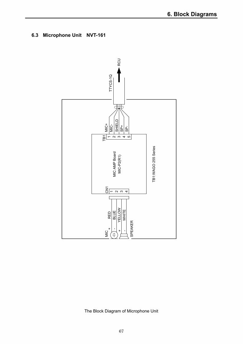
6. Block Diagrams
67
6.3 Microphone Unit NVT-161
The Block Diagram of Microphone Unit
Mic
roph
one
Uni
t (N
VT-
161)
Con
nect
ion
Dia
gram
1 2 3 4
1 2 3 4 5
MIC
RE
DB
LUE
YELL
OW
WH
ITE
SPE
AKE
R
+ -+ -
CN
1TB
1
MIC
-P2(
R1)
MIC
AM
P Bo
ard
TB1:
WA
GO
255
Ser
ies
MIC
+M
IC-
SHIE
LDSP
+SP
-
TTY
CS-
1Q
RC
U
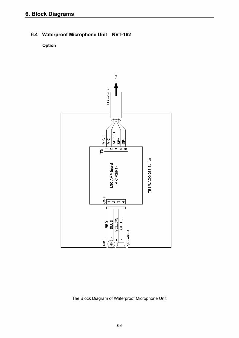
6. Block Diagrams
68
6.4 Waterproof Microphone Unit NVT-162
Option
The Block Diagram of Waterproof Microphone Unit

6. Block Diagrams
69
6.5 Digital Signal Converter (CH64) NCT-72
Option
The Block Diagram of Digital Signal Converter
Dig
ital S
igna
l Con
verto
r 64
CH
(N
CT-
72)
Con
nect
ion
Dia
gram
J2
7ZC
JD01
89A
J202J1
Dry
Con
tact
Inpu
t Boa
rdC
QD
-208
1
P51
AC
/DC
Pow
er S
uppl
y U
nit
AES3
0-12
W10
2
7ZC
JD02
86
PO
WE
R IN
AC
85~
132V
or
AC
170~
265V
AC
Filt
er B
oard
CBJ
-147
CN
1
TB1U V E
IO
FUSE
SW
P1
Dry
Con
tact
Con
trol B
oard
CD
J-23
33
J102
J103
J104
W10
1
Dry
Con
tact
inx6
4ch
TB1
TB2
TB3
1
321
1
1
32
3232
TB4
CH17
CH18
CH19
CH25
CH20CH28
CH21CH29
CH23CH31
CH22
CH30
CH24CH32
CH26
CH27
CH33
CH34
CH35
CH41
CH36
CH44
CH37
CH45
CH39
CH47
CH38
CH46
CH40CH48
CH42
CH43
CH49
CH50
CH51
CH57
CH52
CH60
CH53
CH61
CH55
CH63
CH54
CH62
CH56
CH64
CH58
CH59
CH01
CH02
CH03
CH09
CH04
CH12
CH05
CH13
CH07
CH15
CH06
CH14
CH08CH16
CH10
CH11
TB10
11 5
RC
UN
ME
A d
ata
outp
utTx
+Tx
-G
ND
Rx+ Rx-
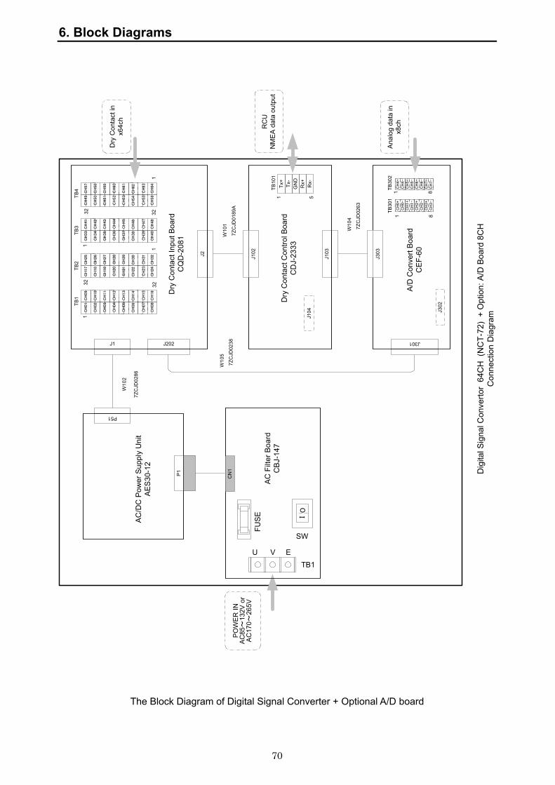
6. Block Diagrams
70
The Block Diagram of Digital Signal Converter + Optional A/D board
Dig
ital S
igna
l Con
verto
r 64
CH
(N
CT-
72)
+ O
ptio
n: A
/D B
oard
8C
HC
onne
ctio
n D
iagr
am
J2
7ZC
JD01
89A
J202J1
Dry
Con
tact
Inpu
t Boa
rdC
QD
-208
1
P51
AC
/DC
Pow
er S
uppl
y U
nit
AES
30-1
2
W10
2
7ZC
JD02
86
PO
WE
R IN
AC
85~
132V
or
AC
170~
265V
AC
Filt
er B
oard
CBJ
-147
CN
1
TB1U V E
IO
FUSE
SW
P1
A/D
Con
vert
Boa
rdC
EF-
60
J303
W10
4
Dry
Con
tact
Con
trol B
oard
CD
J-23
33
J102
J103
7ZC
JD02
63
J301
J104 J3
02
W10
1W
105
7ZC
JD02
38
Dry
Con
tact
inx6
4ch
TB1
TB2
TB3
1
321
1
1
32
3232
TB4
CH17
CH18
CH19
CH25
CH20CH28
CH21CH29
CH23CH31
CH22CH30
CH24
CH32
CH26
CH27
CH33
CH34
CH35
CH41
CH36
CH44
CH37
CH45
CH39
CH47
CH38
CH46
CH40CH48
CH42
CH43
CH49
CH50
CH51
CH57
CH52CH60
CH53CH61
CH55CH63
CH54CH62
CH56CH64
CH58
CH59
CH01
CH02
CH03
CH09
CH04CH12
CH05CH13
CH07CH15
CH06
CH14
CH08CH16
CH10
CH11
TB10
11 5
RC
UN
ME
A d
ata
outp
utTx
+Tx
-G
ND
Rx+ Rx-
Ana
log
data
inx8
chCH0+
CH0-
CH1+
CH1-
CH2+
CH2-
CH3+
CH3-
CH4+
CH4-
CH5+
CH5-
CH6+
CH6-
CH7+
CH7-
TB30
1TB
302
1 8
1 8
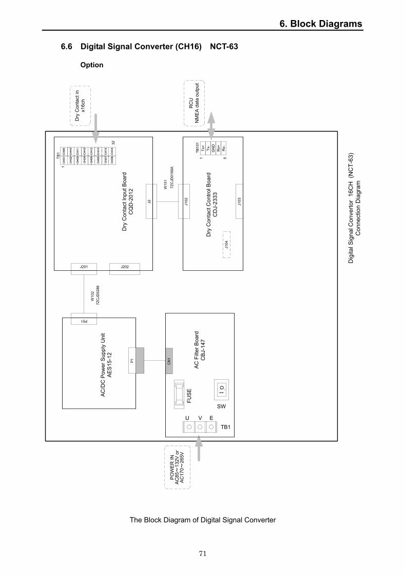
6. Block Diagrams
71
6.6 Digital Signal Converter (CH16) NCT-63
Option
The Block Diagram of Digital Signal Converter
Dig
ital S
igna
l Con
verto
r 16
CH
(N
CT-
63)
Con
nect
ion
Dia
gram
J2
7ZC
JD01
89A
J202J201
Dry
Con
tact
Inpu
t Boa
rdC
QD
-201
2
P51
AC
/DC
Pow
er S
uppl
y U
nit
AES
15-1
2
W10
27Z
CJD
0286
PO
WE
R IN
AC
85~
132V
or
AC
170~
265V
AC F
ilter
Boa
rdC
BJ-
147
CN
1
TB1U V E
IO
FUS
E
SW
P1
Dry
Con
tact
Con
trol B
oard
CD
J-23
33
J102
J103
J104
W10
1
Dry
Con
tact
inx1
6ch
TB1
1
32
CH01
CH02
CH03
CH09
CH04CH12
CH05CH13
CH07CH15
CH06
CH14
CH08
CH16
CH10
CH11 TB
101
1 5
RC
UN
ME
A d
ata
outp
utTx
+Tx
-G
ND
Rx+ Rx-

6. Block Diagrams
72
The Block Diagram of Digital Signal Converter + Optional A/D board
Dig
ital S
igna
l Con
verto
r 16
CH
(N
CT-
63)
+ O
ptio
n: A
/D B
oard
8C
HC
onne
ctio
n D
iagr
am
J2
7ZC
JD01
89A
J202J201
Dry
Con
tact
Inpu
t Boa
rdC
QD
-201
2
P51
AC
/DC
Pow
er S
uppl
y U
nit
AE
S-3
0-12
W10
2
7ZC
JD02
86
PO
WE
R IN
AC
85~
132V
or
AC
170~
265V
AC
Filt
er B
oard
CB
J-14
7
CN
1
TB1U V E
IO
FUS
E
SW
P1
A/D
Con
vert
Boa
rdC
EF-
60J303
W10
4
Dry
Con
tact
Con
trol B
oard
CD
J-23
33
J102
J103
7ZC
JD02
63
J301
J104 J3
02
W10
1W
105
7ZC
JD02
38
TB10
11 5
RC
UN
ME
A d
ata
outp
utTx
+Tx
-G
ND
Rx+ Rx-
Ana
log
data
inx8
chCH0+
CH0-
CH1+
CH1-
CH2+
CH2-
CH3+
CH3-
CH4+
CH4-
CH5+
CH5-
CH6+
CH6-
CH7+
CH7-
TB30
1TB
302
1 8
1 8
Dry
Con
tact
inx1
6ch
TB1
1
32
CH01
CH02
CH03
CH09
CH04
CH12
CH05
CH13
CH07
CH15
CH06CH14
CH08
CH16
CH10
CH11
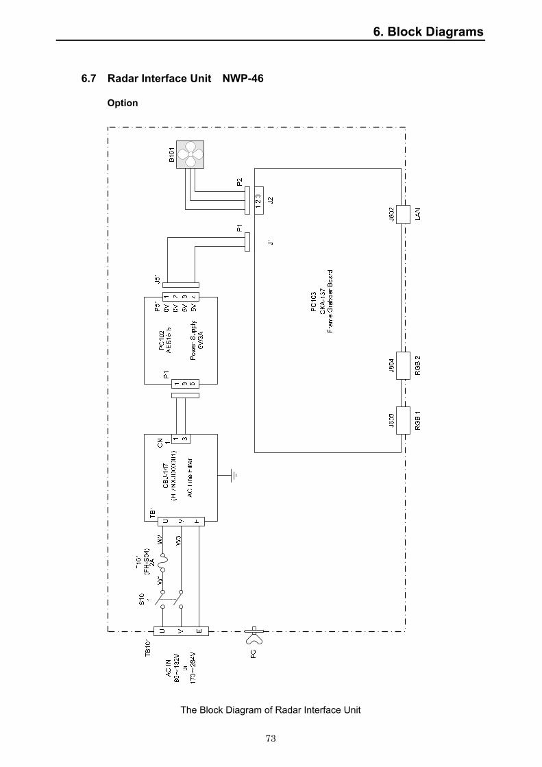
6. Block Diagrams
73
6.7 Radar Interface Unit NWP-46
Option
The Block Diagram of Radar Interface Unit


JCY-1800JCY-1800VOYAGE DATA RECORDERVOYAGE DATA RECORDER
INSTRUCTIONINSTRUCTIONMANUALMANUAL
01ETM ISO 9001, ISO 14001 Certified
Printed in Japan
Marine Service [email protected]
Telephone :Facsimile :e-mail :
AMSTERDAM BranchTelephone :Facsimile :e-mail :
SEATTLE BranchTelephone :Facsimile :e-mail :
CODE No.7ZPJD0385CODE No.7ZPJD0385B
MAYMAY. 2008 Edition 1 JRC. 2008 Edition 1 JRC
Not use the asbestos
For further information,contact:
URL http://www.jrc.co.jp