joslyn joslyn hi-voltage hi-voltage t m overhead reclosers...
TRANSCRIPT
Joslyn Hi-Voltage ® Overhead Reclosers & Switches
In this section...
Joslyn Hi-Voltage® Overhead Reclosers & Switches
TriMod™ Reclosers ..................................................... H-190–H-210
Disconnect Switches.................................................. H-211–H-219
Load Interrupter Attachments..................................... H-220–H-234
www.tnb.comUnited StatesTel: 901.252.8000 800.816.7809Fax: 901.252.1354
Technical ServicesTel: 888.862.3289
H-190
TriMod™ Reclosers
Pow
er &
Hig
h Vo
ltage
— J
osly
n Hi
-Vol
tage
® O
verh
ead
Recl
oser
s &
Switc
hes
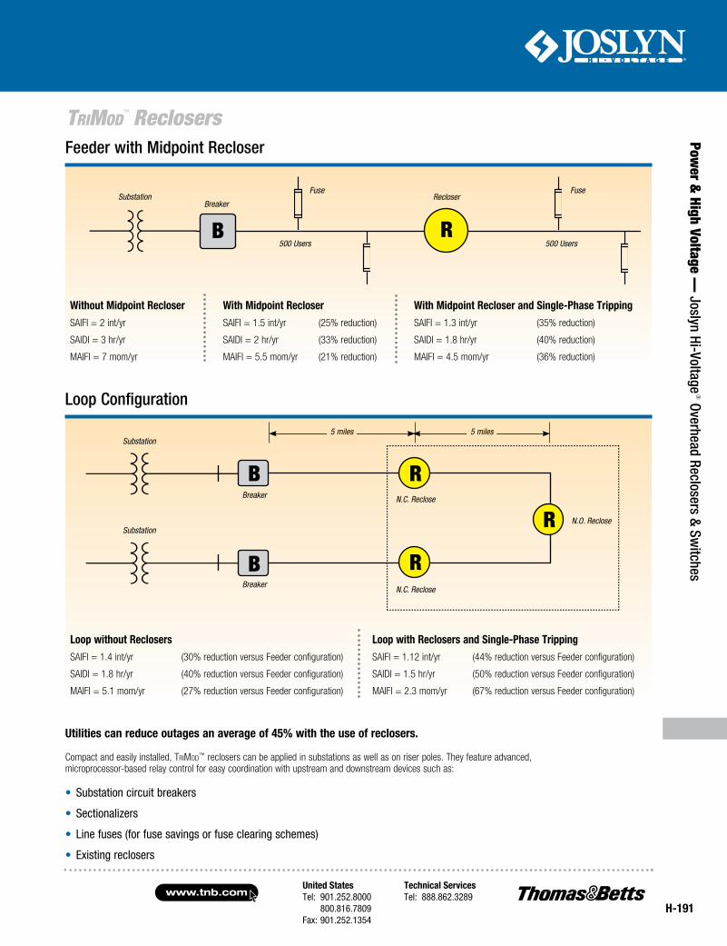
Joslyn TriMod™ automated reclosers feature capabilities well suited for specialty applications that help utilities reduce outages and improve service reliability.
To improve system reliability, many utilities are moving toward system configurations such as:
• Open-tie reclosers
• Midpoint reclosers
• Single-phase reclosing
• Feeder loop restoration
These configurations, when combined with remote communication capability, can substantially improve reliability indices and subsequently enhance customer service.
These indices will measure duration and frequency of interruption for distribution systems and will help assess penalty and/or performance-based rates at the utilities:
• System Average Interruption Frequency Index (SAIFI)
• System Average Interruption Duration Index (SAIDI)
• Momentary Average Interruption Frequency Index (MAIFI)
On the following page are illustrations of typical system reliability improvement applications using TriMod™ reclosers.
• Fault location
• Adaptive protection
• Power quality
• Control monitoring
• SCADA communications
• Single- and three-phase tripping
• Loop automation
Available in both single- and three-phase models, TriMod™ reclosers offer advanced capabilities such as:
Utility companies’ performance is measured by reliability indices.
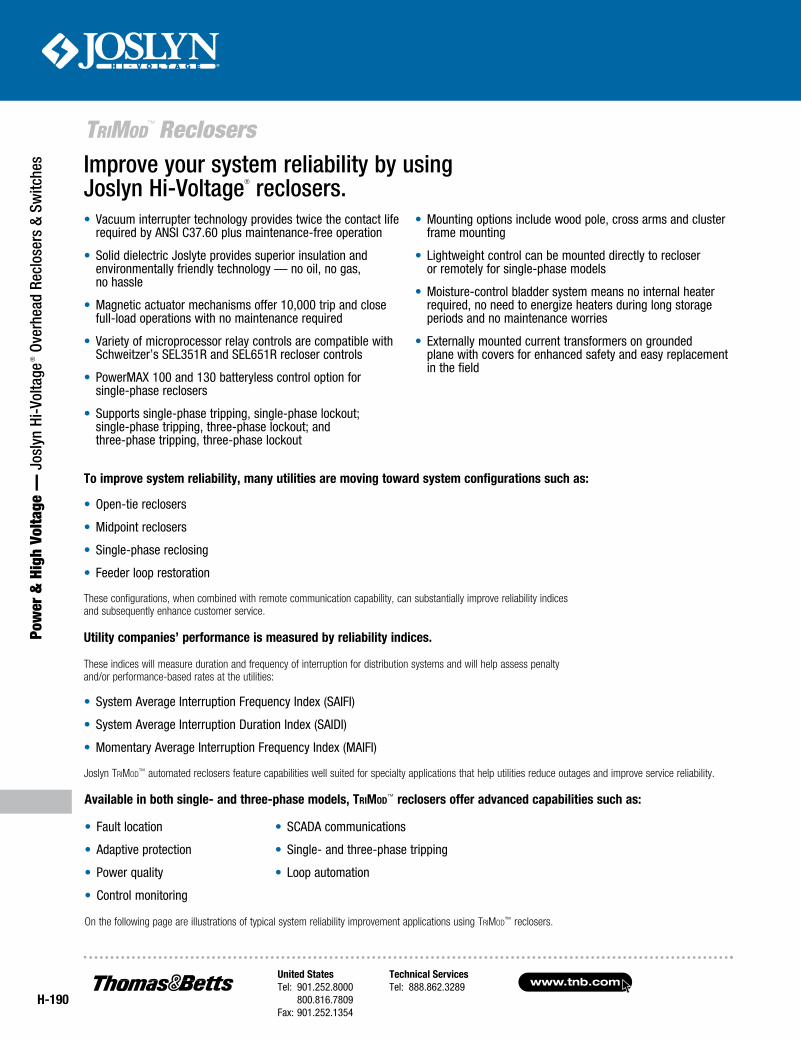
Improve your system reliability by using Joslyn Hi-Voltage® reclosers.• Vacuum interrupter technology provides twice the contact life
required by ANSI C37.60 plus maintenance-free operation
• Solid dielectric Joslyte provides superior insulation and environmentally friendly technology — no oil, no gas, no hassle
• Magnetic actuator mechanisms offer 10,000 trip and close full-load operations with no maintenance required
• Variety of microprocessor relay controls are compatible with Schweitzer’s SEL351R and SEL651R recloser controls
• PowerMAX 100 and 130 batteryless control option for single-phase reclosers
• Supports single-phase tripping, single-phase lockout; single-phase tripping, three-phase lockout; and three-phase tripping, three-phase lockout
• Mounting options include wood pole, cross arms and cluster frame mounting
• Lightweight control can be mounted directly to recloser or remotely for single-phase models
• Moisture-control bladder system means no internal heater required, no need to energize heaters during long storage periods and no maintenance worries
• Externally mounted current transformers on grounded plane with covers for enhanced safety and easy replacement in the field
United StatesTel: 901.252.8000 800.816.7809Fax: 901.252.1354
Technical ServicesTel: 888.862.3289www.tnb.com
H-191
TriMod™ Reclosers
Power &
High Voltage — Joslyn Hi-Voltage
® Overhead Reclosers & Switches
Loop Configuration
Compact and easily installed, TriMod™ reclosers can be applied in substations as well as on riser poles. They feature advanced, microprocessor-based relay control for easy coordination with upstream and downstream devices such as:
• Substation circuit breakers
• Sectionalizers
• Line fuses (for fuse savings or fuse clearing schemes)
• Existing reclosers
Utilities can reduce outages an average of 45% with the use of reclosers.
Breaker
FuseSubstation
500 Users 500 Users
Fuse
Breaker
Breaker
Substation
Substation
N.C. Reclose
N.C. Reclose
N.O. Reclose
Feeder with Midpoint Recloser
Recloser
R
R
R
R
B
B
B
Without Midpoint Recloser With Midpoint Recloser With Midpoint Recloser and Single-Phase TrippingSAIFI = 2 int/yr SAIFI = 1.5 int/yr (25% reduction) SAIFI = 1.3 int/yr (35% reduction)
SAIDI = 3 hr/yr SAIDI = 2 hr/yr (33% reduction) SAIDI = 1.8 hr/yr (40% reduction)
MAIFI = 7 mom/yr MAIFI = 5.5 mom/yr (21% reduction) MAIFI = 4.5 mom/yr (36% reduction)
Loop without Reclosers Loop with Reclosers and Single-Phase TrippingSAIFI = 1.4 int/yr (30% reduction versus Feeder configuration) SAIFI = 1.12 int/yr (44% reduction versus Feeder configuration)
SAIDI = 1.8 hr/yr (40% reduction versus Feeder configuration) SAIDI = 1.5 hr/yr (50% reduction versus Feeder configuration)
MAIFI = 5.1 mom/yr (27% reduction versus Feeder configuration) MAIFI = 2.3 mom/yr (67% reduction versus Feeder configuration)
5 miles 5 miles
www.tnb.comUnited StatesTel: 901.252.8000 800.816.7809Fax: 901.252.1354
Technical ServicesTel: 888.862.3289
H-192
Pow
er &
Hig
h Vo
ltage
— J
osly
n Hi
-Vol
tage
® O
verh
ead
Recl
oser
s &
Switc
hes
TriMod™ Reclosers
• Vacuum interrupter technology provides twice the duty-cycle interruption life and uses no oil or gas for interruption
• Joslyte solid dielectric insulating system provides maintenance-free, environmentally safe operation, with no need to monitor or maintain gas pressure or oil levels
• Magnetic actuator system yields a minimum of 10,000 operations with no maintenance required
• PowerMAX 100 microprocessor-based control offers reliable accuracy regardless of time and temperature — plus it offers features traditionally only available with three-phase recloser controls
• Mounts to a wood pole, cross arms or cluster mounting frame — with control mounted directly to TriMod™ recloser or remotely
• Manual operating handles on recloser for mechanical opening and lockout and disabling automatic reclosing
• Large color-coded reflective open and closed position indicators located on bottom of recloser for easy visibility from ground level
• Durable module materials: upper housing — cycloaliphatic epoxy, lower housing — aluminum casting
• Externally mounted current transformers on grounded plane with covers for enhanced safety and easy replacement in the field
Raising the standard of recloser performance and reliability.
Joslyn Hi-Voltage® TriMod™ 100 Series
Single-Phase Vacuum Recloser
The Joslyn Hi-Voltage® TriMod™ 100 Series Single-Phase Vacuum Recloser raises the standard of recloser performance by incorporating state-of-the-art vacuum interrupter technology with Joslyn’s field-proven Joslyte solid dielectric insulating system and a long-life operating mechanism and magnetic actuator system. Unique, field-proven features make the TriMod™ 100 Series Recloser the long-life, easy-to-use solution for utility recloser needs.
The TriMod™ 100 Recloser contains no oil or gas for interruption or insulation. The 40-year field-proven Joslyte solid dielectric insulation system provides dielectric strength around the vacuum interrupter without the danger of leaks or environmental hazards.
Traditional single-phase reclosers with hydraulic controls have difficulty maintaining accuracy over time, particularly through temperature variations. This can affect coordination and limit protection flexibility. Conversely, the TriMod™ 100 Series Recloser features microprocessor-based PowerMAX control. Its accuracy does not change over time or with temperature variations, thus enabling better and more reliable protection coordination.
For user convenience, manual operating handles are located on the recloser. The yellow handle permits mechanical opening and mechanically actuated, electrical closing of the recloser. The non-reclosing lever provides the capability of blocking reclosing after the first trip operation regardless of the number of recloses pre-programmed in the control.
TriMod™ 100 Series Vacuum-Interrupting, Single-Phase, Microprocessor-Controlled
Automatic Circuit Recloser
United StatesTel: 901.252.8000 800.816.7809Fax: 901.252.1354
Technical ServicesTel: 888.862.3289www.tnb.com
H-193
Power &
High Voltage — Joslyn Hi-Voltage
® Overhead Reclosers & Switches
TriMod™ Reclosers
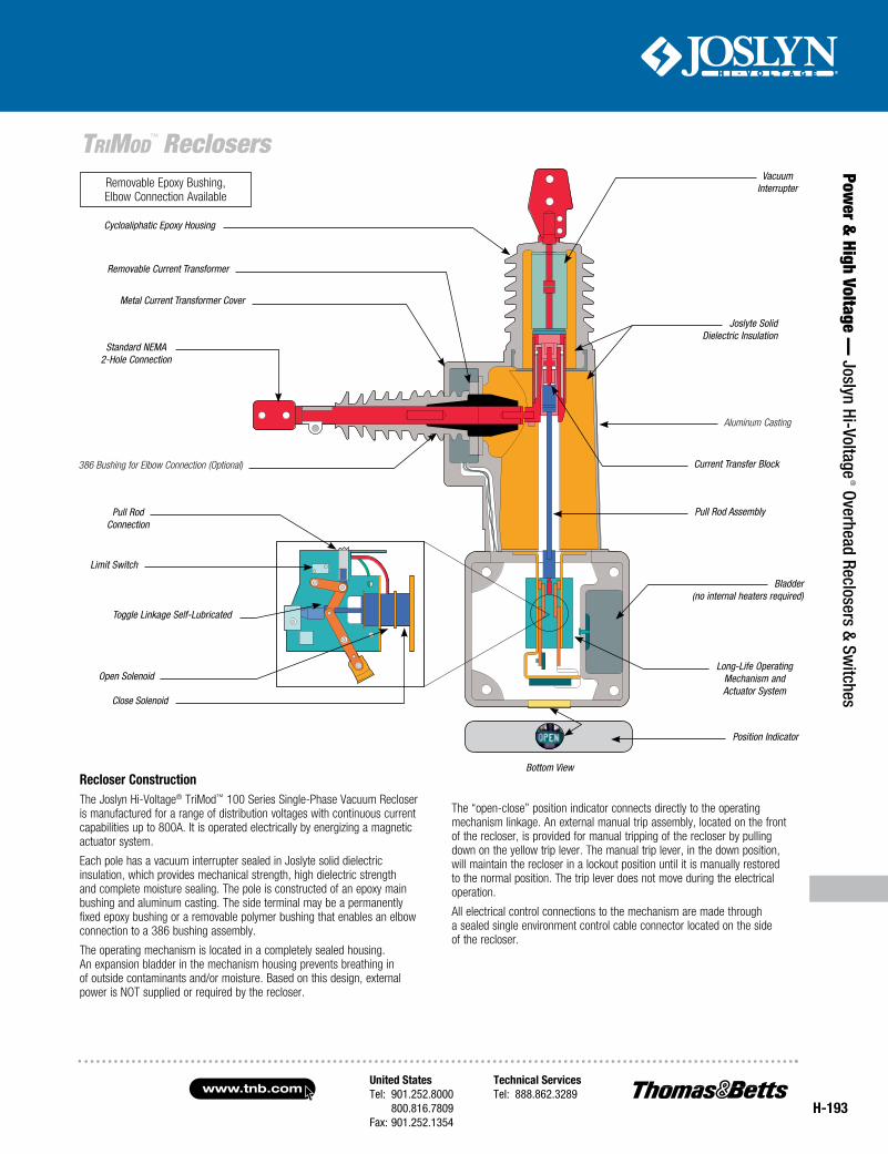
Recloser ConstructionThe Joslyn Hi-Voltage® TriMod™ 100 Series Single-Phase Vacuum Recloser is manufactured for a range of distribution voltages with continuous current capabilities up to 800A. It is operated electrically by energizing a magnetic actuator system.
Each pole has a vacuum interrupter sealed in Joslyte solid dielectric insulation, which provides mechanical strength, high dielectric strength and complete moisture sealing. The pole is constructed of an epoxy main bushing and aluminum casting. The side terminal may be a permanently fixed epoxy bushing or a removable polymer bushing that enables an elbow connection to a 386 bushing assembly.
The operating mechanism is located in a completely sealed housing. An expansion bladder in the mechanism housing prevents breathing in of outside contaminants and/or moisture. Based on this design, external power is NOT supplied or required by the recloser.
The “open-close” position indicator connects directly to the operating mechanism linkage. An external manual trip assembly, located on the front of the recloser, is provided for manual tripping of the recloser by pulling down on the yellow trip lever. The manual trip lever, in the down position, will maintain the recloser in a lockout position until it is manually restored to the normal position. The trip lever does not move during the electrical operation.
All electrical control connections to the mechanism are made through a sealed single environment control cable connector located on the side of the recloser.
Open Solenoid
Cycloaliphatic Epoxy Housing
Joslyte Solid Dielectric Insulation
Current Transfer Block
Aluminum Casting
Pull Rod Assembly
Bladder (no internal heaters required)
Long-Life Operating Mechanism and Actuator System
Position Indicator
Bottom View
Removable Current Transformer
Metal Current Transformer Cover
Standard NEMA 2-Hole Connection
Removable Epoxy Bushing, Elbow Connection Available
386 Bushing for Elbow Connection (Optional)
Close Solenoid
Limit Switch
Pull RodConnection
Toggle Linkage Self-Lubricated
Vacuum Interrupter
www.tnb.comUnited StatesTel: 901.252.8000 800.816.7809Fax: 901.252.1354
Technical ServicesTel: 888.862.3289
H-194
Pow
er &
Hig
h Vo
ltage
— J
osly
n Hi
-Vol
tage
® O
verh
ead
Recl
oser
s &
Switc
hes
TriMod™ Reclosers
Enhanced FeaturesThe PowerMAX 100 control unit offers features traditionally only available with three-phase recloser controls. The microprocessor-based control uses only a small lithium clock battery to maintain accurate time and date event stamping. The unit’s enhanced accuracy and reliability means that its timing remains constant and is not affected by temperature.
No other batteries are used in the operation of the control, thus eliminating costly battery maintenance normally associated with electronic controls. All settings and stored information are retained without the use of batteries — even in the absence of line voltage.
The PowerMAX 100 control unit is incredibly versatile. It can be mounted directly to the TriMod™ 100 Series Recloser or conveniently placed at a remote location. What’s more, connecting the control unit to other PowerMAX 100 controllers provides single-phase tripping and three-phase lockout.
Programmable SettingsProgramming of the PowerMAX 100 control unit is easily accomplished with the self-explanatory keypad. No DIP switches or additional components are required to make any setting changes. All settings are changeable from the keypad, and no computer is required. Changes to the settings and retrieval of stored information can be accomplished with a computer using the ControlMAX interface software.
Time-Current CurvesAll traditional single-phase recloser curves plus ANSI inverse curves are user-programmable without the need to change any components. Select from A, B, C, D, E, F, N, R, EF, KF and TF (with modifier curves).
Voltage ProtectionThe PowerMAX 100 control unit has the ability to be programmed to trip on overvoltage or undervoltage conditions.
Single-Phase Trip, Three-Phase LockoutThe PowerMAX 100 control unit may be connected to other PowerMAX controls to provide single-phase tripping and three-phase lockout.
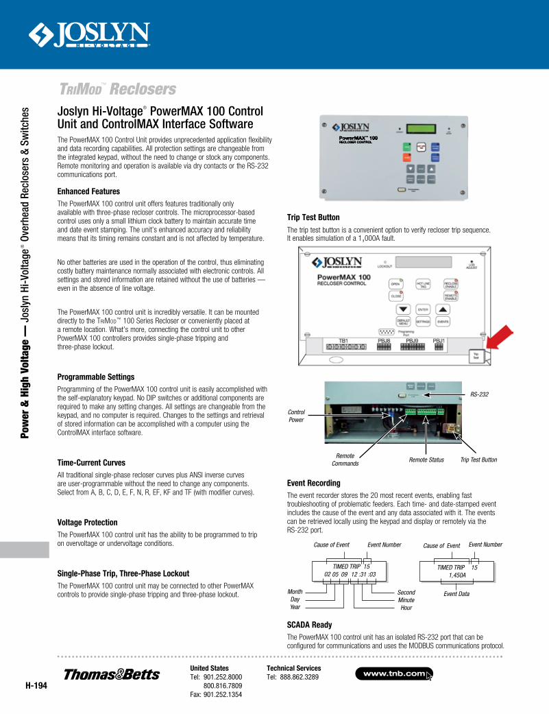
Trip Test ButtonThe trip test button is a convenient option to verify recloser trip sequence. It enables simulation of a 1,000A fault.
Joslyn Hi-Voltage® PowerMAX 100 Control Unit and ControlMAX Interface SoftwareThe PowerMAX 100 Control Unit provides unprecedented application flexibility and data recording capabilities. All protection settings are changeable from the integrated keypad, without the need to change or stock any components. Remote monitoring and operation is available via dry contacts or the RS-232 communications port.
RS-232
Control Power
Remote Commands Remote Status Trip Test Button
TIMED TRIP 15 02
TIMED TRIP 151,450A
MonthDayYear
SecondMinuteHour
Cause of Event
05 09 12 :31 :03
Event Number Cause of Event
Event RecordingThe event recorder stores the 20 most recent events, enabling fast troubleshooting of problematic feeders. Each time- and date-stamped event includes the cause of the event and any data associated with it. The events can be retrieved locally using the keypad and display or remotely via the RS-232 port.
SCADA ReadyThe PowerMAX 100 control unit has an isolated RS-232 port that can be configured for communications and uses the MODBUS communications protocol.
Event Data
Event Number
United StatesTel: 901.252.8000 800.816.7809Fax: 901.252.1354
Technical ServicesTel: 888.862.3289www.tnb.com
H-195
Power &
High Voltage — Joslyn Hi-Voltage
® Overhead Reclosers & Switches
TriMod™ Reclosers
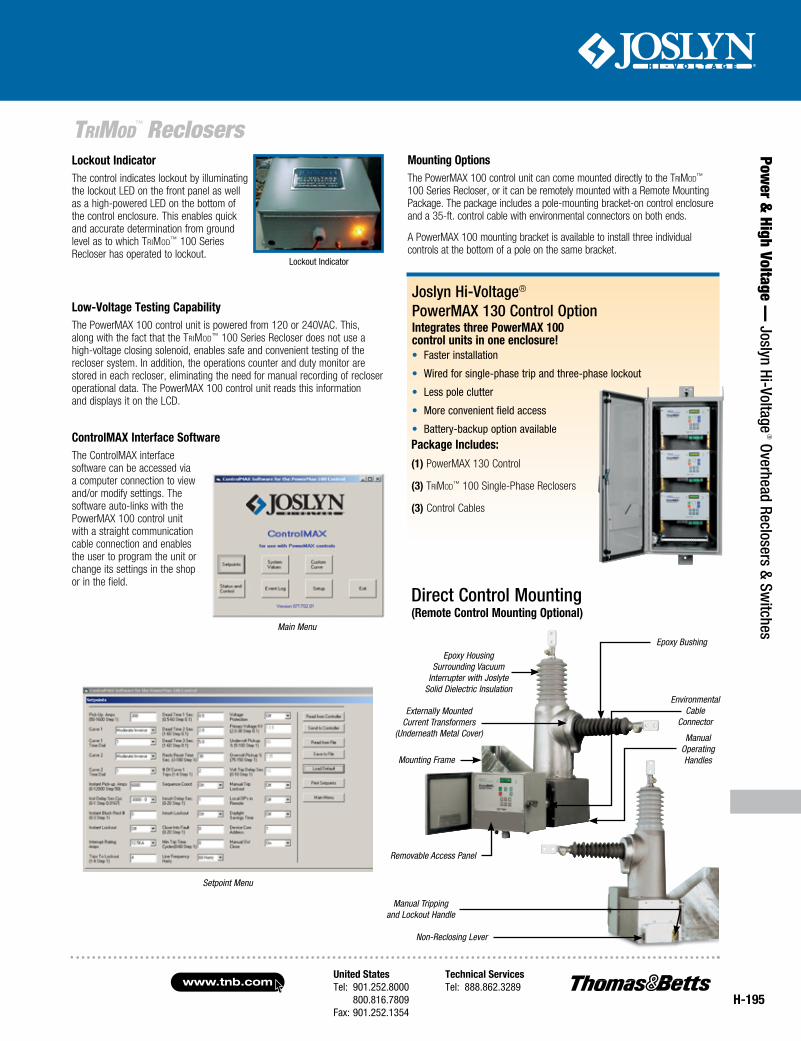
ControlMAX Interface SoftwareThe ControlMAX interface software can be accessed via a computer connection to view and/or modify settings. The software auto-links with the PowerMAX 100 control unit with a straight communication cable connection and enables the user to program the unit or change its settings in the shop or in the field.
Integrates three PowerMAX 100 control units in one enclosure!
Package Includes:(1) PowerMAX 130 Control
(3) TriMod™ 100 Single-Phase Reclosers
(3) Control Cables
Joslyn Hi-Voltage® PowerMAX 130 Control Option
• Faster installation
• Wired for single-phase trip and three-phase lockout
• Less pole clutter
• More convenient field access
• Battery-backup option available
Manual Tripping and Lockout Handle
Removable Access Panel
Epoxy Bushing
Externally Mounted Current Transformers
(Underneath Metal Cover)
Environmental Cable
Connector
Manual Operating Handles
(Remote Control Mounting Optional)
Epoxy Housing Surrounding Vacuum
Interrupter with Joslyte Solid Dielectric Insulation
Mounting Frame
Non-Reclosing Lever
Direct Control Mounting
Main Menu
Low-Voltage Testing CapabilityThe PowerMAX 100 control unit is powered from 120 or 240VAC. This, along with the fact that the TriMod™ 100 Series Recloser does not use a high-voltage closing solenoid, enables safe and convenient testing of the recloser system. In addition, the operations counter and duty monitor are stored in each recloser, eliminating the need for manual recording of recloser operational data. The PowerMAX 100 control unit reads this information and displays it on the LCD.
Lockout IndicatorThe control indicates lockout by illuminating the lockout LED on the front panel as well as a high-powered LED on the bottom of the control enclosure. This enables quick and accurate determination from ground level as to which TriMod™ 100 Series Recloser has operated to lockout.
Lockout Indicator
Mounting OptionsThe PowerMAX 100 control unit can come mounted directly to the TriMod™ 100 Series Recloser, or it can be remotely mounted with a Remote Mounting Package. The package includes a pole-mounting bracket-on control enclosure and a 35-ft. control cable with environmental connectors on both ends.
A PowerMAX 100 mounting bracket is available to install three individual controls at the bottom of a pole on the same bracket.
Setpoint Menu
www.tnb.comUnited StatesTel: 901.252.8000 800.816.7809Fax: 901.252.1354
Technical ServicesTel: 888.862.3289
H-196
Pow
er &
Hig
h Vo
ltage
— J
osly
n Hi
-Vol
tage
® O
verh
ead
Recl
oser
s &
Switc
hes
TriMod™ Reclosers
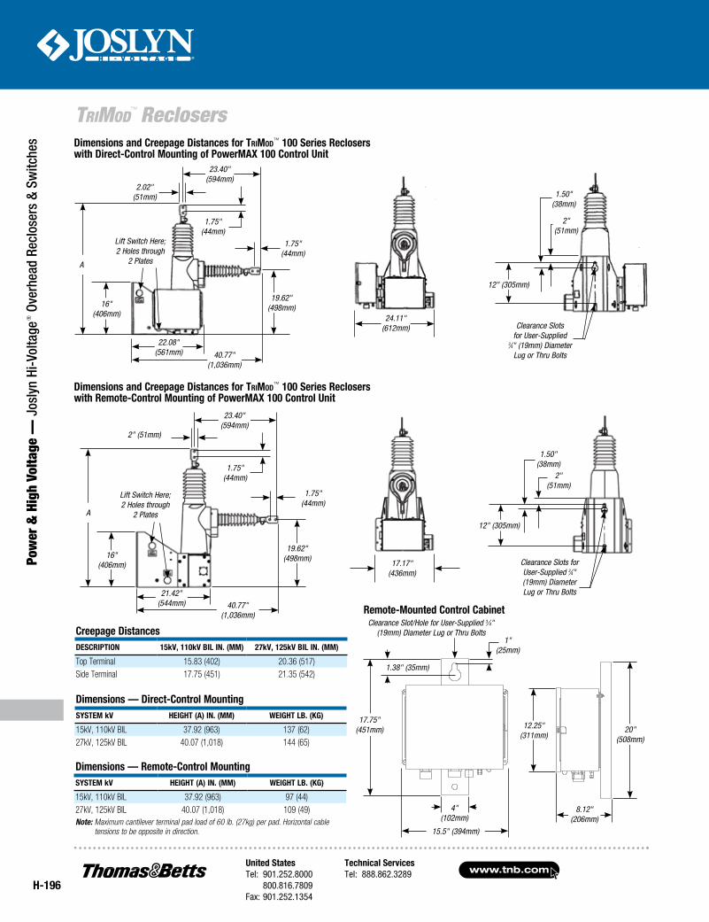
Dimensions and Creepage Distances for TriMod™ 100 Series Reclosers with Direct-Control Mounting of PowerMAX 100 Control Unit
16" (406mm)
19.62" (498mm)
2.02" (51mm)
23.40" (594mm)
22.08" (561mm) 40.77"
(1,036mm)
1.75" (44mm)
1.75" (44mm)
A
Lift Switch Here;2 Holes through
2 Plates
24.11" (612mm)
16" (406mm)
19.62" (498mm)
2" (51mm)
23.40" (594mm)
21.42" (544mm) 40.77"
(1,036mm)
1.75" (44mm)
1.75" (44mm)
A
Lift Switch Here;2 Holes through
2 Plates
17.17" (436mm)
12" (305mm)
1.50" (38mm)
2" (51mm)
Clearance Slots for User-Supplied 3⁄4" (19mm) Diameter Lug or Thru Bolts
Dimensions — Remote-Control MountingSySteM kV HeigHt (A) in. (MM) WeigHt lb. (kg)
15kV, 110kV BIL 37.92 (963) 97 (44)27kV, 125kV BIL 40.07 (1,018) 109 (49)Note: Maximum cantilever terminal pad load of 60 lb. (27kg) per pad. Horizontal cable
tensions to be opposite in direction.
Creepage DistancesDeSCRiPtion 15kV, 110kV bil in. (MM) 27kV, 125kV bil in. (MM)
Top Terminal 15.83 (402) 20.36 (517)Side Terminal 17.75 (451) 21.35 (542)
Dimensions — Direct-Control MountingSySteM kV HeigHt (A) in. (MM) WeigHt lb. (kg)
15kV, 110kV BIL 37.92 (963) 137 (62)27kV, 125kV BIL 40.07 (1,018) 144 (65)
12" (305mm)
1.50" (38mm)
2" (51mm)
Clearance Slotsfor User-Supplied
3⁄4" (19mm) Diameter Lug or Thru Bolts
Remote-Mounted Control Cabinet
8.12" (206mm)
12.25"(311mm)
20"(508mm)
Dimensions and Creepage Distances for TriMod™ 100 Series Reclosers with Remote-Control Mounting of PowerMAX 100 Control Unit
4" (102mm)
1.38" (35mm)
1" (25mm)
17.75" (451mm)
15.5" (394mm)
Clearance Slot/Hole for User-Supplied 3⁄4" (19mm) Diameter Lug or Thru Bolts
United StatesTel: 901.252.8000 800.816.7809Fax: 901.252.1354
Technical ServicesTel: 888.862.3289www.tnb.com
H-197
Power &
High Voltage — Joslyn Hi-Voltage
® Overhead Reclosers & Switches
TriMod™ Reclosers
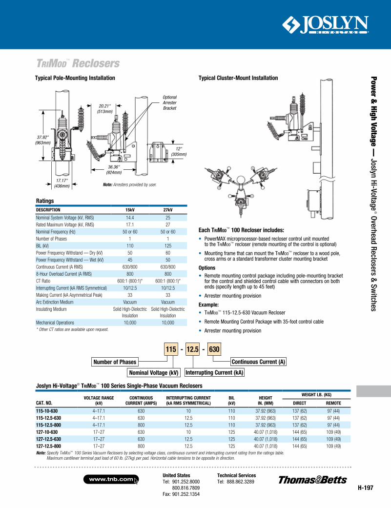
typical Cluster-Mount installation
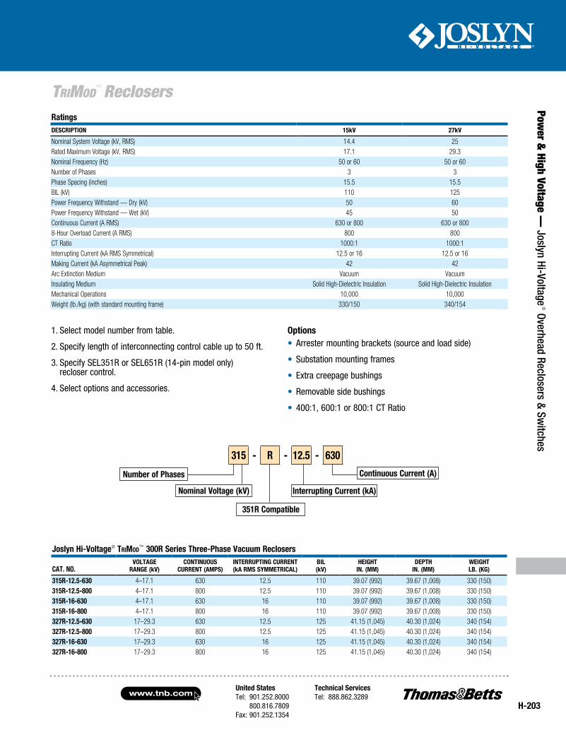
RatingsDeSCRiPtion 15kV 27kV
Nominal System Voltage (kV, RMS) 14.4 25Rated Maximum Voltage (kV, RMS) 17.1 27Nominal Frequency (Hz) 50 or 60 50 or 60Number of Phases 1 1BIL (kV) 110 125Power Frequency Withstand — Dry (kV) 50 60Power Frequency Withstand — Wet (kV) 45 50Continuous Current (A RMS) 630/800 630/8008-Hour Overload Current (A RMS) 800 800CT Ratio 600:1 (800:1)* 600:1 (800:1)*Interrupting Current (kA RMS Symmetrical) 10/12.5 10/12.5Making Current (kA Asymmetrical Peak) 33 33Arc Extinction Medium Vacuum VacuumInsulating Medium Solid High-Dielectric
InsulationSolid High-Dielectric
InsulationMechanical Operations 10,000 10,000* Other CT ratios are available upon request.
Joslyn Hi-Voltage® TriMod™ 100 Series Single-Phase Vacuum Reclosers
CAt. no.VoltAge RAnge
(kV)ContinUoUS
CURRent (AMPS)inteRRUPting CURRent(kA RMS SyMMetRiCAl)
bil(kV)
HeigHtin. (MM)
WeigHt lb. (kg)
DiReCt ReMote
115-10-630 4–17.1 630 10 110 37.92 (963) 137 (62) 97 (44)115-12.5-630 4–17.1 630 12.5 110 37.92 (963) 137 (62) 97 (44)115-12.5-800 4–17.1 800 12.5 110 37.92 (963) 137 (62) 97 (44)127-10-630 17–27 630 10 125 40.07 (1,018) 144 (65) 109 (49)127-12.5-630 17–27 630 12.5 125 40.07 (1,018) 144 (65) 109 (49)127-12.5-800 17–27 800 12.5 125 40.07 (1,018) 144 (65) 109 (49)Note: Specify TriMod™ 100 Series Vacuum Reclosers by selecting voltage class, continuous current and interrupting current rating from the ratings table.
Maximum cantilever terminal pad load of 60 lb. (27kg) per pad. Horizontal cable tensions to be opposite in direction.
each TriMod™ 100 Recloser includes:• PowerMAXmicroprocessor-basedreclosercontrolunitmounted
totheTriMod™recloser(remotemountingofthecontrolisoptional)
• MountingframethatcanmounttheTriMod™reclosertoawoodpole,crossarmsorastandardtransformerclustermountingbracket
options• Remotemountingcontrolpackageincludingpole-mountingbracket
forthecontrolandshieldedcontrolcablewithconnectorsonbothends(specifylengthupto45feet)
• Arrestermountingprovision
example:• TriMod™115-12.5-630VacuumRecloser
• RemoteMountingControlPackagewith35-footcontrolcable
• Arrestermountingprovision
typical Pole-Mounting installation
Note: Arresters provided by user.
37.92" (963mm)
17.17" (436mm)
36.36"(924mm)
12"(305mm)
20.21" (513mm)
Optional Arrester Bracket
number of Phases
nominal Voltage (kV)
Continuous Current (A)
interrupting Current (kA)
115 - 12.5 - 630
www.tnb.comUnited StatesTel: 901.252.8000 800.816.7809Fax: 901.252.1354
Technical ServicesTel: 888.862.3289
H-198
Pow
er &
Hig
h Vo
ltage
— J
osly
n Hi
-Vol
tage
® O
verh
ead
Recl
oser
s &
Switc
hes
TriMod™ Reclosers
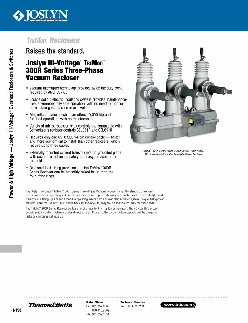
Raises the standard.
Joslyn Hi-Voltage® TriMod™
300R Series Three-Phase Vacuum Recloser
The Joslyn Hi-Voltage® TriMod™ 300R Series Three-Phase Vacuum Recloser raises the standard of recloser performance by incorporating state-of-the-art vacuum interrupter technology with Joslyn’s field-proven Joslyte solid dielectric insulating system and a long-life operating mechanism and magnetic actuator system. Unique, field-proven features make the TriMod™ 300R Series Recloser the long-life, easy-to-use solution for utility recloser needs.
The TriMod™ 300R Series Recloser contains no oil or gas for interruption or insulation. The 40-year field-proven Joslyte solid insulation system provides dielectric strength around the vacuum interrupter without the danger of leaks or environmental hazards.
TriMod™ 300R Series Vacuum-Interrupting, Three-Phase, Microprocessor-Controlled Automatic Circuit Recloser
• Vacuum interrupter technology provides twice the duty cycle required by ANSI C37.60
• Joslyte solid dielectric insulating system provides maintenance-free, environmentally safe operation, with no need to monitor or maintain gas pressure or oil levels
• Magnetic actuator mechanism offers 10,000 trip and full-load operations with no maintenance
• Variety of microprocessor relay controls are compatible with Schweitzer’s recloser controls SEL351R and SEL651R
• Requires only one C510 SEL 14-pin control cable — faster and more economical to install than other reclosers, which require up to three cables
• Externally mounted current transformers on grounded plane with covers for enhanced safety and easy replacement in the field
• Balanced load-lifting provisions — the TriMod™ 300R Series Recloser can be smoothly raised by utilizing the four lifting rings
United StatesTel: 901.252.8000 800.816.7809Fax: 901.252.1354
Technical ServicesTel: 888.862.3289www.tnb.com
H-199
Power &
High Voltage — Joslyn Hi-Voltage
® Overhead Reclosers & Switches
TriMod™ Reclosers
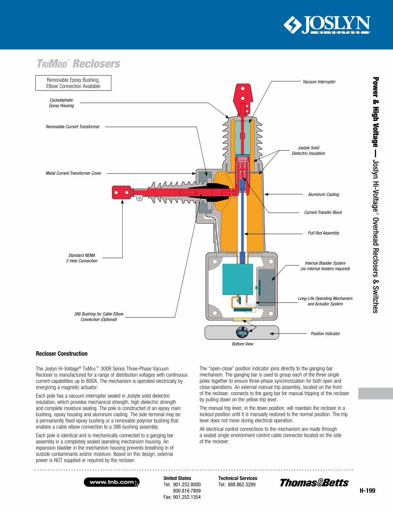
Recloser Construction
The Joslyn Hi-Voltage® TriMod™ 300R Series Three-Phase Vacuum Recloser is manufactured for a range of distribution voltages with continuous current capabilities up to 800A. The mechanism is operated electrically by energizing a magnetic actuator.
Each pole has a vacuum interrupter sealed in Joslyte solid dielectric insulation, which provides mechanical strength, high dielectric strength and complete moisture sealing. The pole is constructed of an epoxy main bushing, epoxy housing and aluminum casting. The side terminal may be a permanently fixed epoxy bushing or a removable polymer bushing that enables a cable elbow connection to a 386 bushing assembly.
Each pole is identical and is mechanically connected to a ganging bar assembly in a completely sealed operating mechanism housing. An expansion bladder in the mechanism housing prevents breathing in of outside contaminants and/or moisture. Based on this design, external power is NOT supplied or required by the recloser.
The “open-close” position indicator joins directly to the ganging bar mechanism. The ganging bar is used to group each of the three single poles together to ensure three-phase synchronization for both open and close operations. An external manual trip assembly, located on the front of the recloser, connects to the gang bar for manual tripping of the recloser by pulling down on the yellow trip lever.
The manual trip lever, in the down position, will maintain the recloser in a lockout position until it is manually restored to the normal position. The trip lever does not move during electrical operation.
All electrical control connections to the mechanism are made through a sealed single environment control cable connector located on the side of the recloser.
Bottom View
Vacuum Interrupter
Joslyte Solid Dielectric Insulation
Current Transfer Block
Aluminum Casting
Pull Rod Assembly
Position Indicator
Internal Bladder System (no internal heaters required )
Long-Life Operating Mechanism and Actuator System
Cycloaliphatic Epoxy Housing
Removable Current Transformer
Metal Current Transformer Cover
Standard NEMA 2-Hole Connection
386 Bushing for Cable Elbow Connection (Optional)
Removable Epoxy Bushing, Elbow Connection Available
www.tnb.comUnited StatesTel: 901.252.8000 800.816.7809Fax: 901.252.1354
Technical ServicesTel: 888.862.3289
H-200
Pow
er &
Hig
h Vo
ltage
— J
osly
n Hi
-Vol
tage
® O
verh
ead
Recl
oser
s &
Switc
hes
TriMod™ Reclosers
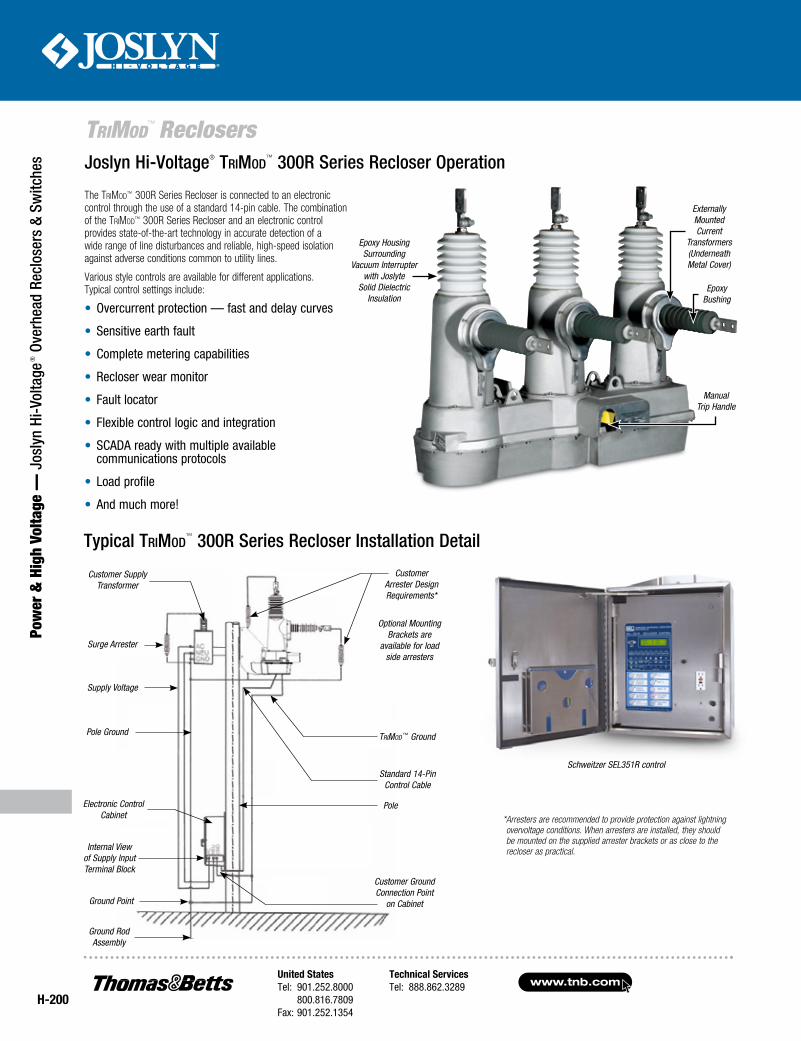
The TriMod™ 300R Series Recloser is connected to an electronic control through the use of a standard 14-pin cable. The combination of the TriMod™ 300R Series Recloser and an electronic control provides state-of-the-art technology in accurate detection of a wide range of line disturbances and reliable, high-speed isolation against adverse conditions common to utility lines.
Various style controls are available for different applications. Typical control settings include:
• Overcurrent protection — fast and delay curves
• Sensitive earth fault
• Complete metering capabilities
• Recloser wear monitor
• Fault locator
• Flexible control logic and integration
• SCADA ready with multiple available communications protocols
• Load profile
• And much more!
Joslyn Hi-Voltage® TriMod™ 300R Series Recloser Operation
Epoxy Housing Surrounding
Vacuum Interrupter with Joslyte
Solid Dielectric Insulation
Epoxy Bushing
Manual Trip Handle
Externally Mounted Current
Transformers (Underneath Metal Cover)
Schweitzer SEL351R control
Typical TriMod™ 300R Series Recloser Installation Detail
* Arresters are recommended to provide protection against lightning overvoltage conditions. When arresters are installed, they should be mounted on the supplied arrester brackets or as close to the recloser as practical.
Customer Arrester Design Requirements*
Optional Mounting Brackets are
available for load side arresters
TriMod™ Ground
Standard 14-Pin Control Cable
Pole
Customer Ground Connection Point
on Cabinet
Surge Arrester
Supply Voltage
Pole Ground
Ground Point
Ground Rod Assembly
Customer Supply Transformer
Electronic Control Cabinet
Internal View of Supply Input Terminal Block
United StatesTel: 901.252.8000 800.816.7809Fax: 901.252.1354
Technical ServicesTel: 888.862.3289www.tnb.com
H-201
Power &
High Voltage — Joslyn Hi-Voltage
® Overhead Reclosers & Switches
TriMod™ Reclosers
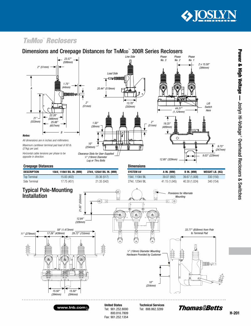
Dimensions and Creepage Distances for TriMod™ 300R Series Reclosers
Creepage DistancesDesCription 15kV, 110kV BiL in. (mm) 27kV, 125kV BiL in. (mm)
Top Terminal 15.83 (402) 20.36 (517)Side Terminal 17.75 (451) 21.35 (542)
Notes:
All dimensions are in inches and millimeters.
Maximum cantilever terminal pad load of 60 lb. (27kg) per pad.
Horizontal cable tensions per phase to be opposite in direction.
2 x 15.50" (394mm)
44.27" (1,124mm)
Lift Switch Here
PhaseNo. 3
PhaseNo. 2
PhaseNo. 1
2" (51mm)
1.50" (38mm)
10" (254mm)
Clearance Slots for User-Supplied 3⁄4" (19mm) Diameter
Lug or Thru Bolts
19.25" (489mm)
9.73" (247mm)
9.03" (229mm)12.95" (329mm)
23.57" (599mm)
2" (51mm)
A
21" (533mm)
1.75" (44mm)
2" (51mm)
22.28" (566mm)
B
25.88" (657mm)
Line Side
Load Side
13.78" (350mm)
20.44" (519mm)
Dimensionssystem kV A in. (mm) B in. (mm) WeigHt LB. (kg)
15kV, 110kV BIL 39.07 (992) 39.67 (1,008) 330 (150)27kV, 125kV BIL 41.15 (1,045) 40.30 (1,024) 340 (154)
Typical Pole-Mounting Installation
10" (254mm)
3⁄4" (19mm) Diameter Mounting Hardware Provided by Customer
33.77" (858mm) from Pole to Terminal Pad
12.84" (326mm)
21.8
5" (5
55m
m) Provisions for Alternate
Mounting
15.50" (394mm)
15.50" (394mm)
11" (279mm)58" (1,473mm)
29.72" (755mm)17.26" (439mm)
www.tnb.comUnited StatesTel: 901.252.8000 800.816.7809Fax: 901.252.1354
Technical ServicesTel: 888.862.3289
H-202
Pow
er &
Hig
h Vo
ltage
— J
osly
n Hi
-Vol
tage
® O
verh
ead
Recl
oser
s &
Switc
hes
TriMod™ Reclosers
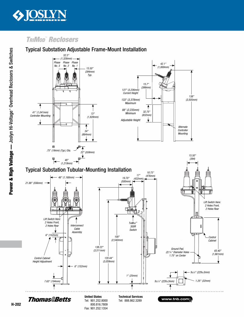
Typical Substation Adjustable Frame-Mount Installation
Typical Substation Tubular-Mounting Installation
Phase No. 3
Phase No. 2
Phase No. 1
48" (1,219mm)
41" (1,041mm) Controller Mounting
34" (864mm)
72" (1,828mm)
22" (559mm).75" (19mm) (Typ.) Dia.
52.3" (1,328mm)
15.50" (394mm)
Typ.
46" (1,168mm)
21.88" (556mm)
Interconnect Cable
Assembly
Lift Switch Here:2 Holes Front,2 Holes Rear
6" (152mm)
Control Cabinet Height Adjustment
6" (152mm)
7.63" (194mm)
1" (25mm)
100" (2,540mm)
138.22" (3,511mm)
19.70" (500mm)
17" (432mm)
18.75" (476mm)
120.44" (3,059mm)
TriMod™ 300R
Switch
15.50" (394)
Lift Switch Here:2 Holes Front,2 Holes Rear
Control Cabinet
Ground Pad,(2) 9⁄16" Diameter Holes
1.75" on Center
65.40" (1,661mm)
32.75" (832mm)
42.1" (1,069mm)
15.7" (399mm)
138" (3,505mm)
Alternate Controller Mounting
127" (3,226mm) Current Height
133" (3,378mm) Maximum
88" (2,235mm) Minimum
Adjustable Height
9±1⁄8" (229±3mm)
9±1⁄8" (229±3mm)
1.25" (32mm)
United StatesTel: 901.252.8000 800.816.7809Fax: 901.252.1354
Technical ServicesTel: 888.862.3289www.tnb.com
H-203
Power &
High Voltage — Joslyn Hi-Voltage
® Overhead Reclosers & Switches
TriMod™ Reclosers
Joslyn Hi-Voltage® TriMod™ 300R Series Three-Phase Vacuum Reclosers
CAT. NO.VOlTAge
RANge (kV)CONTiNuOuS
CuRReNT (AmPS)iNTeRRuPTiNg CuRReNT(kA RmS SymmeTRiCAl)
Bil(kV)
HeigHTiN. (mm)
DePTHiN. (mm)
WeigHTlB. (kg)
315R-12.5-630 4–17.1 630 12.5 110 39.07 (992) 39.67 (1,008) 330 (150)315R-12.5-800 4–17.1 800 12.5 110 39.07 (992) 39.67 (1,008) 330 (150)315R-16-630 4–17.1 630 16 110 39.07 (992) 39.67 (1,008) 330 (150)315R-16-800 4–17.1 800 16 110 39.07 (992) 39.67 (1,008) 330 (150)327R-12.5-630 17–29.3 630 12.5 125 41.15 (1,045) 40.30 (1,024) 340 (154)327R-12.5-800 17–29.3 800 12.5 125 41.15 (1,045) 40.30 (1,024) 340 (154)327R-16-630 17–29.3 630 16 125 41.15 (1,045) 40.30 (1,024) 340 (154)327R-16-800 17–29.3 800 16 125 41.15 (1,045) 40.30 (1,024) 340 (154)
RatingsDeSCRiPTiON 15kV 27kV
Nominal System Voltage (kV, RMS) 14.4 25Rated Maximum Voltage (kV, RMS) 17.1 29.3Nominal Frequency (Hz) 50 or 60 50 or 60Number of Phases 3 3Phase Spacing (inches) 15.5 15.5BIL (kV) 110 125Power Frequency Withstand — Dry (kV) 50 60Power Frequency Withstand — Wet (kV) 45 50Continuous Current (A RMS) 630 or 800 630 or 8008-Hour Overload Current (A RMS) 800 800CT Ratio 1000:1 1000:1Interrupting Current (kA RMS Symmetrical) 12.5 or 16 12.5 or 16Making Current (kA Asymmetrical Peak) 42 42Arc Extinction Medium Vacuum VacuumInsulating Medium Solid High-Dielectric Insulation Solid High-Dielectric InsulationMechanical Operations 10,000 10,000Weight (lb./kg) (with standard mounting frame) 330/150 340/154
Options• Arrester mounting brackets (source and load side)
• Substation mounting frames
• Extra creepage bushings
• Removable side bushings
• 400:1, 600:1 or 800:1 CT Ratio
1. Select model number from table.
2. Specify length of interconnecting control cable up to 50 ft.
3. Specify SEL351R or SEL651R (14-pin model only) recloser control.
4. Select options and accessories.
315 - R - 12.5 - 630
Number of Phases
Nominal Voltage (kV)
Continuous Current (A)
interrupting Current (kA)
351R Compatible
www.tnb.comUnited StatesTel: 901.252.8000 800.816.7809Fax: 901.252.1354
Technical ServicesTel: 888.862.3289
H-204
Pow
er &
Hig
h Vo
ltage
— J
osly
n Hi
-Vol
tage
® O
verh
ead
Recl
oser
s &
Switc
hes
TriMod™ Reclosers
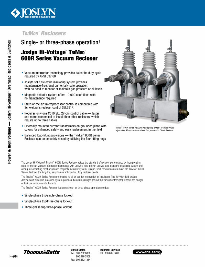
Single- or three-phase operation!
Joslyn Hi-Voltage® TriMod™
600R Series Vacuum Recloser
The Joslyn Hi-Voltage® TriMod™ 600R Series Recloser raises the standard of recloser performance by incorporating state-of-the-art vacuum interrupter technology with Joslyn’s field-proven Joslyte solid dielectric insulating system and a long-life operating mechanism and magnetic actuator system. Unique, field-proven features make the TriMod™ 600R Series Recloser the long-life, easy-to-use solution for utility recloser needs.
The TriMod™ 600R Series Recloser contains no oil or gas for interruption or insulation. The 40-year field-proven Joslyte solid dielectric insulation system provides dielectric strength around the vacuum interrupter without the danger of leaks or environmental hazards.
The TriMod™ 600R Series Recloser features single- or three-phase operation modes:
• Single-phase trip/single-phase lockout
• Single-phase trip/three-phase lockout
• Three-phase trip/three-phase lockout
TriMod™ 600R Series Vacuum-Interrupting, Single- or Three-Phase Operation, Microprocessor-Controlled, Automatic Circuit Recloser
• Vacuum interrupter technology provides twice the duty cycle required by ANSI C37.60
• Joslyte solid dielectric insulating system provides maintenance-free, environmentally safe operation, with no need to monitor or maintain gas pressure or oil levels
• Magnetic actuator system offers 10,000 operations with no maintenance required
• State-of-the-art microprocessor control is compatible with Schweitzer’s recloser control SEL651R
• Requires only one C510 SEL 27-pin control cable — faster and more economical to install than other reclosers, which require up to three cables
• Externally mounted current transformers on grounded plane with covers for enhanced safety and easy replacement in the field
• Balanced load-lifting provisions — the TriMod™ 600R Series Recloser can be smoothly raised by utilizing the four lifting rings
United StatesTel: 901.252.8000 800.816.7809Fax: 901.252.1354
Technical ServicesTel: 888.862.3289www.tnb.com
H-205
Power &
High Voltage — Joslyn Hi-Voltage
® Overhead Reclosers & Switches
TriMod™ Reclosers
Cycloaliphatic Epoxy Housing
Bladder (no internal heaters required)
Long-Life Operating Mechanism and Actuator System
Position Indicator
per Phase
Removable Current Transformer
Current Transformer Metal Cover
386 Bushing for Elbow Connection (Optional)
Close Solenoid
Recloser Construction
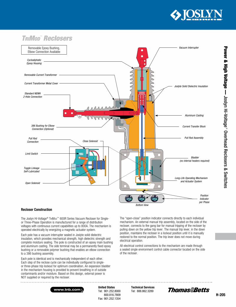
The Joslyn Hi-Voltage® TriMod™ 600R Series Vacuum Recloser for Single- or Three-Phase Operation is manufactured for a range of distribution voltages with continuous current capabilities up to 800A. The mechanism is operated electrically by energizing a magnetic actuator system.
Each pole has a vacuum interrupter sealed in Joslyte solid dielectric insulation, which provides mechanical strength, high dielectric strength and complete moisture sealing. The pole is constructed of an epoxy main bushing and aluminum casting. The side terminal may be a permanently fixed epoxy bushing or a removable polymer bushing that enables an elbow connection to a 386 bushing assembly.
Each pole is identical and is mechanically independent of each other. Each step of the reclose cycle can be individually configured to single- or three-phase trip lockout for optimum coordination. An expansion bladder in the mechanism housing is provided to prevent breathing in of outside contaminants and/or moisture. Based on this design, external power is NOT supplied or required by the recloser.
The “open-close” position indicator connects directly to each individual mechanism. An external manual trip assembly, located on the side of the recloser, connects to the gang bar for manual tripping of the recloser by pulling down on the yellow trip lever. The manual trip lever, in the down position, maintains the recloser in a lockout position until it is manually restored to the normal position. The trip lever does not move during electrical operation.
All electrical control connections to the mechanism are made through a sealed single environment control cable connector located on the side of the recloser.
Bottom View
Standard NEMA 2-Hole Connection
Pull Rod Connection
Limit Switch
Toggle Linkage Self-Lubricated
Open Solenoid
Vacuum Interrupter
Joslyte Solid Dielectric Insulation
Current Transfer Block
Aluminum Casting
Pull Rod Assembly
Removable Epoxy Bushing, Elbow Connection Available
www.tnb.comUnited StatesTel: 901.252.8000 800.816.7809Fax: 901.252.1354
Technical ServicesTel: 888.862.3289
H-206
Pow
er &
Hig
h Vo
ltage
— J
osly
n Hi
-Vol
tage
® O
verh
ead
Recl
oser
s &
Switc
hes
TriMod™ Reclosers
Customer Supply Transformer
Customer Arrester Design Requirements*
TriMod™ Ground
27-Pin Control Cable
Pole
Customer Ground Connection Point
on Cabinet
Surge Arrester
Supply Voltage
Pole Ground
Electronic Control Cabinet
Internal View of Supply Input Terminal Block
Ground Point
Ground Rod Assembly
* Arresters are recommended to provide protection against lightning overvoltage conditions. When arresters are installed, they should be mounted on the supplied arrester brackets or as close to the recloser as practical.
Joslyn Hi-Voltage® TriMod™ 600R Series Recloser Operation
Epoxy Bushing (Cable Elbow Connection Compatible)
Current Transformers Externally Mounted
(Underneath Metal Cover)
Lifting Holes
Arrester Mounting Bracket Provision
Epoxy Housing Surrounds the Vacuum Interrupter
with Joslyte Solid Dielectric Insulation
Enviromental Cable Connector
Pole-Mounting Bracket
Manual Trip Lever
Typical TriMod™ 600R Series Recloser Installation Detail
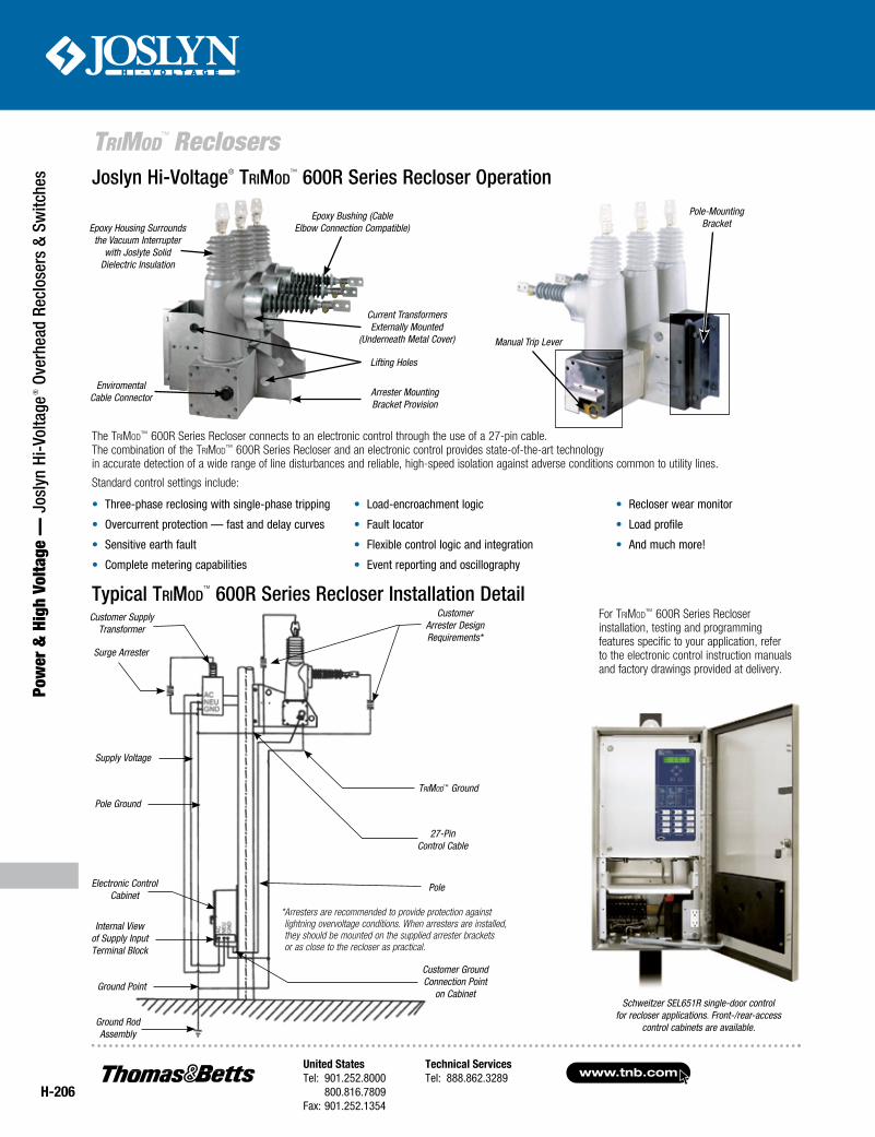
The TriMod™ 600R Series Recloser connects to an electronic control through the use of a 27-pin cable. The combination of the TriMod™ 600R Series Recloser and an electronic control provides state-of-the-art technology in accurate detection of a wide range of line disturbances and reliable, high-speed isolation against adverse conditions common to utility lines.
Standard control settings include:
• Three-phase reclosing with single-phase tripping
• Overcurrent protection — fast and delay curves
• Sensitive earth fault
• Complete metering capabilities
• Load-encroachment logic
• Fault locator
• Flexible control logic and integration
• Event reporting and oscillography
• Recloser wear monitor
• Load profile
• And much more!
For TriMod™ 600R Series Recloser installation, testing and programming features specific to your application, refer to the electronic control instruction manuals and factory drawings provided at delivery.
Schweitzer SEL651R single-door control for recloser applications. Front-/rear-access
control cabinets are available.
United StatesTel: 901.252.8000 800.816.7809Fax: 901.252.1354
Technical ServicesTel: 888.862.3289www.tnb.com
H-207
Power &
High Voltage — Joslyn Hi-Voltage
® Overhead Reclosers & Switches
TriMod™ Reclosers
Provisions for Alternate Mounting
13.01 (330mm)
21.12 (537mm)
Dimensions and Creepage Distances for TriMod™ 600R Series Reclosers
Line Side
Load Side
2.04" (52mm)
20.20" (513mm)
1.50" (38mm) 2" (51mm)
12" (305mm)
Clearance Slots for User-Supplied 3⁄4" (19mm) Diameter Lug or Thru Bolts
Phase No. 3
Phase No. 2
Phase No. 1 2 x 12.25"
(311mm)
40.44" (1,027mm).52" (13mm)
12.31" (313mm)
6.31" (160mm)
3.13" (80mm)
9.29" (236mm)
9.37" (238mm)
19.40" (493mm)
Lift Switch Here,
2 Holes through 2 Plates
1.75" (44mm)
2" (51mm)
16" (406mm)
2" (51mm)
25.38" (645mm) 41.12" (1,044mm)
A
23.37" (594mm)
1.75" (44mm)
LIFTHERE
LIFTHERELIFTHERE
LIFTHERE
39" (989mm) from Pole to Terminal Pad
Lift Switch Here, 2 Holes through 2 Plates
3⁄4" (19mm) Dia. Mounting Hardware
Provided by Customer
12" (305mm)
Typical Pole-Mounting Installation
11.23" (285mm)
12.25" (311mm)
12.25" (311mm)
29.25" (743mm)
18.02" (458mm)
58.50 (1,486mm)
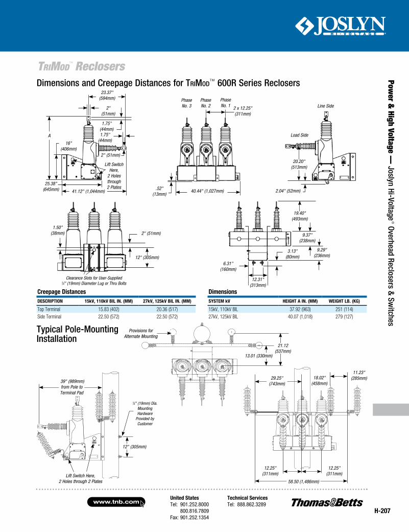
Creepage DistancesDesCription 15kV, 110kV BiL in. (mm) 27kV, 125kV BiL in. (mm)
Top Terminal 15.83 (402) 20.36 (517)Side Terminal 22.50 (572) 22.50 (572)
Dimensionssystem kV HeiGHt A in. (mm) WeiGHt LB. (kG)
15kV, 110kV BIL 37.92 (963) 251 (114)27kV, 125kV BIL 40.07 (1,018) 279 (127)
www.tnb.comUnited StatesTel: 901.252.8000 800.816.7809Fax: 901.252.1354
Technical ServicesTel: 888.862.3289
H-208
Pow
er &
Hig
h Vo
ltage
— J
osly
n Hi
-Vol
tage
® O
verh
ead
Recl
oser
s &
Switc
hes
TriMod™ Reclosers
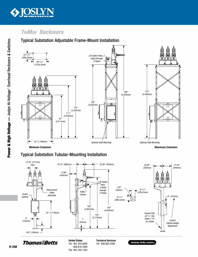
Typical Substation Adjustable Frame-Mount Installation
53" (1,346mm)
91" (2,311mm)
111" (2,819mm)
132" (3,353mm)
155" (3,937mm)
196" (4,978mm)
175" (4,445mm)
Lift Switch Here, 2 Holes through
2 Plates48"±1⁄8" (1219±3mm)
22"±1⁄8" (559±3mm)
Typical Substation Tubular-Mounting Installation
TriMod™ Switch
Lift Switch Here,
2 Holes through 2 Plates
19.14" (486mm)
17.88" (454mm)
23.36" (593mm)
1" (25mm)
125" (3,175mm)
105" (2,667mm)
144" (3,658mm)
6" (152mm)
Control Cabinet Height
Adjustment
Ground Pad, (2) 9⁄16" Dia. Holes 1.75" on Center
21.42" (544mm)
20.95" (532mm)
7.63" (194mm)
12.25" (311mm) (Typ.)
6" (152mm)
Interconnect Cable
AssemblyContol Cabinet
70" (1,778mm)
9"±1⁄8" (229±3mm)
1.25" (32mm) 9"±1⁄8"
(229±3mm)
Minimum Extension Maximum Extension
Optional Side MountingOptional Side Mounting
United StatesTel: 901.252.8000 800.816.7809Fax: 901.252.1354
Technical ServicesTel: 888.862.3289www.tnb.com
H-209
Power &
High Voltage — Joslyn Hi-Voltage
® Overhead Reclosers & Switches
TriMod™ Reclosers
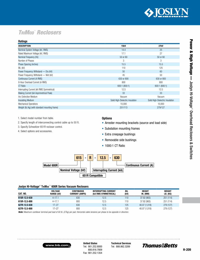
Options• Arrester mounting brackets (source and load side)
• Substation mounting frames
• Extra creepage bushings
• Removable side bushings
• 1000:1 CT Ratio
1. Select model number from table.
2. Specify length of interconnecting control cable up to 50 ft.
3. Specify Schweitzer 651R recloser control.
4. Select options and accessories.
Joslyn Hi-Voltage® TriMod™ 600R Series Vacuum Reclosers
CAT. NO.VOlTAgE
RANgE (kV)CONTiNuOuS
CuRRENT (AMpS)iNTERRupTiNg CuRRENT(kA RMS SyMMETRiCAl)
Bil(kV)
HEigHTiN. (MM)
WEigHTlB. (kg)
615R-12.5-630 4–17.1 630 12.5 110 37.92 (963) 251 (114)615R-12.5-800 4–17.1 800 12.5 110 37.92 (963) 251 (114)627R-12.5-630 17–27 630 12.5 125 40.07 (1,018) 279 (127)627R-12.5-800 17–27 800 12.5 125 40.07 (1,018) 279 (127)Note: Maximum cantilever terminal pad load of 60 lb. (27kg) per pad. Horizontal cable tensions per phase to be opposite in direction.
RatingsDESCRipTiON 15kV 27kV
Nominal System Voltage (kV, RMS) 14.4 25Rated Maximum Voltage (kV, RMS) 17.1 27Nominal Frequency (Hz) 50 or 60 50 or 60Number of Phases 3 3Phase Spacing (inches) 15.5 15.5BIL (kV) 110 125Power Frequency Withstand — Dry (kV) 50 60Power Frequency Withstand — Wet (kV) 45 50Continuous Current (A RMS) 630 or 800 630 or 8008-Hour Overload Current (A RMS) 800 800CT Ratio 600:1 (800:1) 600:1 (800:1)Interrupting Current (kA RMS Symmetrical) 12.5 12.5Making Current (kA Asymmetrical Peak) 33 33Arc Extinction Medium Vacuum VacuumInsulating Medium Solid High-Dielectric Insulation Solid High-Dielectric InsulationMechanical Operations 10,000 10,000Weight (lb./kg) (with standard mounting frame) 251/113 279/127
Model 600R
Nominal Voltage (kV)
Continuous Current (A)
interrupting Current (kA)
615 - R - 12.5 - 630
651R Compatible
www.tnb.comUnited StatesTel: 901.252.8000 800.816.7809Fax: 901.252.1354
Technical ServicesTel: 888.862.3289
H-210
TriMod™ Reclosers
Pow
er &
Hig
h Vo
ltage
— J
osly
n Hi
-Vol
tage
® O
verh
ead
Recl
oser
s &
Switc
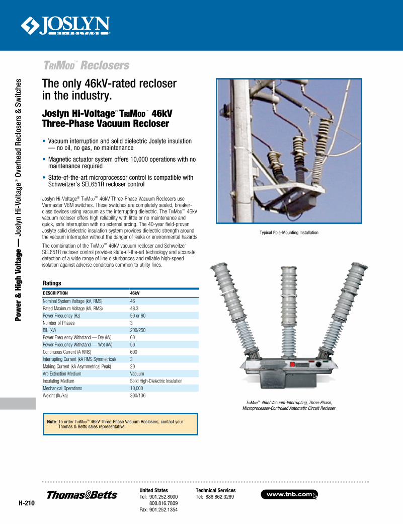
hes The only 46kV-rated recloser
in the industry.
Joslyn Hi-Voltage® TriMod™ 46kV Three-Phase Vacuum Reclosers use Varmaster VBM switches. These switches are completely sealed, breaker-class devices using vacuum as the interrupting dielectric. The TriMod™ 46kV vacuum recloser offers high reliability with little or no maintenance and quick, safe interruption with no external arcing. The 40-year field-proven Joslyte solid dielectric insulation system provides dielectric strength around the vacuum interrupter without the danger of leaks or environmental hazards.
The combination of the TriMod™ 46kV vacuum recloser and Schweitzer SEL651R recloser control provides state-of-the-art technology and accurate detection of a wide range of line disturbances and reliable high-speed isolation against adverse conditions common to utility lines.
TriMod™ 46kV Vacuum-Interrupting, Three-Phase, Microprocessor-Controlled Automatic Circuit Recloser
• Vacuum interruption and solid dielectric Joslyte insulation — no oil, no gas, no maintenance
• Magnetic actuator system offers 10,000 operations with no maintenance required
• State-of-the-art microprocessor control is compatible with Schweitzer’s SEL651R recloser control
RatingsDescRiption 46kV
Nominal System Voltage (kV, RMS) 46Rated Maximum Voltage (kV, RMS) 48.3Power Frequency (Hz) 50 or 60Number of Phases 3BIL (kV) 200/250Power Frequency Withstand — Dry (kV) 60Power Frequency Withstand — Wet (kV) 50Continuous Current (A RMS) 600Interrupting Current (kA RMS Symmetrical) 3Making Current (kA Asymmetrical Peak) 20Arc Extinction Medium Vacuum Insulating Medium Solid High-Dielectric InsulationMechanical Operations 10,000Weight (lb./kg) 300/136
Typical Pole-Mounting Installation
Joslyn Hi-Voltage® TriMod™ 46kV
Three-Phase Vacuum Recloser
note: To order TriMod™ 46kV Three-Phase Vacuum Reclosers, contact your Thomas & Betts sales representative.
United StatesTel: 901.252.8000 800.816.7809Fax: 901.252.1354
Technical ServicesTel: 888.862.3289www.tnb.com
Disconnect Switches
Power &
High Voltage — Joslyn Hi-Voltage
® Overhead Reclosers & Switches
H-211
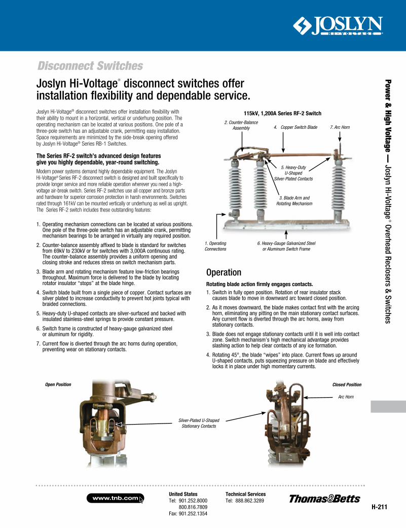
1. Operating Connections
2. Counter-Balance Assembly
3. Blade Arm and Rotating Mechanism
4. Copper Switch Blade
5. Heavy-Duty U-Shaped
Silver-Plated Contacts
6. Heavy-Gauge Galvanized Steel or Aluminum Switch Frame
7. Arc Horn
115kV, 1,200A series RF-2 switch
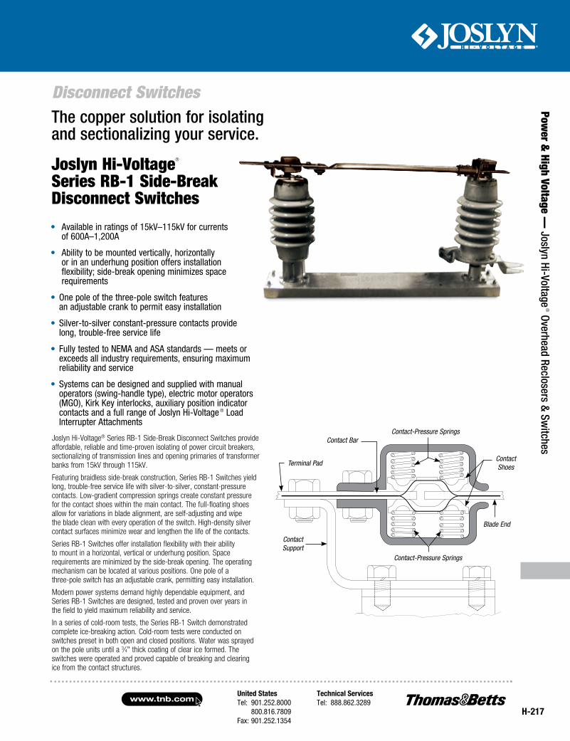
Joslyn Hi-Voltage® disconnect switches offer installation flexibility and dependable service.Joslyn Hi-Voltage® disconnect switches offer installation flexibility with their ability to mount in a horizontal, vertical or underhung position. The operating mechanism can be located at various positions. One pole of a three-pole switch has an adjustable crank, permitting easy installation. Space requirements are minimized by the side-break opening offered by Joslyn Hi-Voltage® Series RB-1 Switches.
OperationRotating blade action firmly engages contacts.1. Switch in fully open position. Rotation of rear insulator stack
causes blade to move in downward arc toward closed position.
2. As it moves downward, the blade makes contact first with the arcing horn, eliminating any pitting on the main stationary contact surfaces. Any current flow is diverted through the arc horns, away from stationary contacts.
3. Blade does not engage stationary contacts until it is well into contact zone. Switch mechanism’s high mechanical advantage provides slashing action to help clear contacts of any ice formation.
4. Rotating 45°, the blade “wipes” into place. Current flows up around U-shaped contacts, puts squeezing pressure on blade and effectively locks it in place under high momentary currents.
the series RF-2 switch’s advanced design features give you highly dependable, year-round switching.Modern power systems demand highly dependable equipment. The Joslyn Hi-Voltage® Series RF-2 disconnect switch is designed and built specifically to provide longer service and more reliable operation wherever you need a high-voltage air-break switch. Series RF-2 switches use all copper and bronze parts and hardware for superior corrosion protection in harsh environments. Switches rated through 161kV can be mounted vertically or underhung as well as upright. The Series RF-2 switch includes these outstanding features:
1. Operating mechanism connections can be located at various positions. One pole of the three-pole switch has an adjustable crank, permitting mechanism bearings to be arranged in virtually any required position.
2. Counter-balance assembly affixed to blade is standard for switches from 69kV to 230kV or for switches with 3,000A continuous rating. The counter-balance assembly provides a uniform opening and closing stroke and reduces stress on switch mechanism parts.
3. Blade arm and rotating mechanism feature low-friction bearings throughout. Maximum force is delivered to the blade by locating rotator insulator “stops” at the blade hinge.
4. Switch blade built from a single piece of copper. Contact surfaces are silver plated to increase conductivity to prevent hot joints typical with braided connections.
5. Heavy-duty U-shaped contacts are silver-surfaced and backed with insulated stainless-steel springs to provide constant pressure.
6. Switch frame is constructed of heavy-gauge galvanized steel or aluminum for rigidity.
7. Current flow is diverted through the arc horns during operation, preventing wear on stationary contacts.
Silver-Plated U-Shaped Stationary Contacts
Open Position Closed Position
Arc Horn
www.tnb.comUnited StatesTel: 901.252.8000 800.816.7809Fax: 901.252.1354
Technical ServicesTel: 888.862.3289
H-212
Disconnect Switches
Pow
er &
Hig
h Vo
ltage
— J
osly
n Hi
-Vol
tage
® O
verh
ead
Recl
oser
s &
Switc
hes
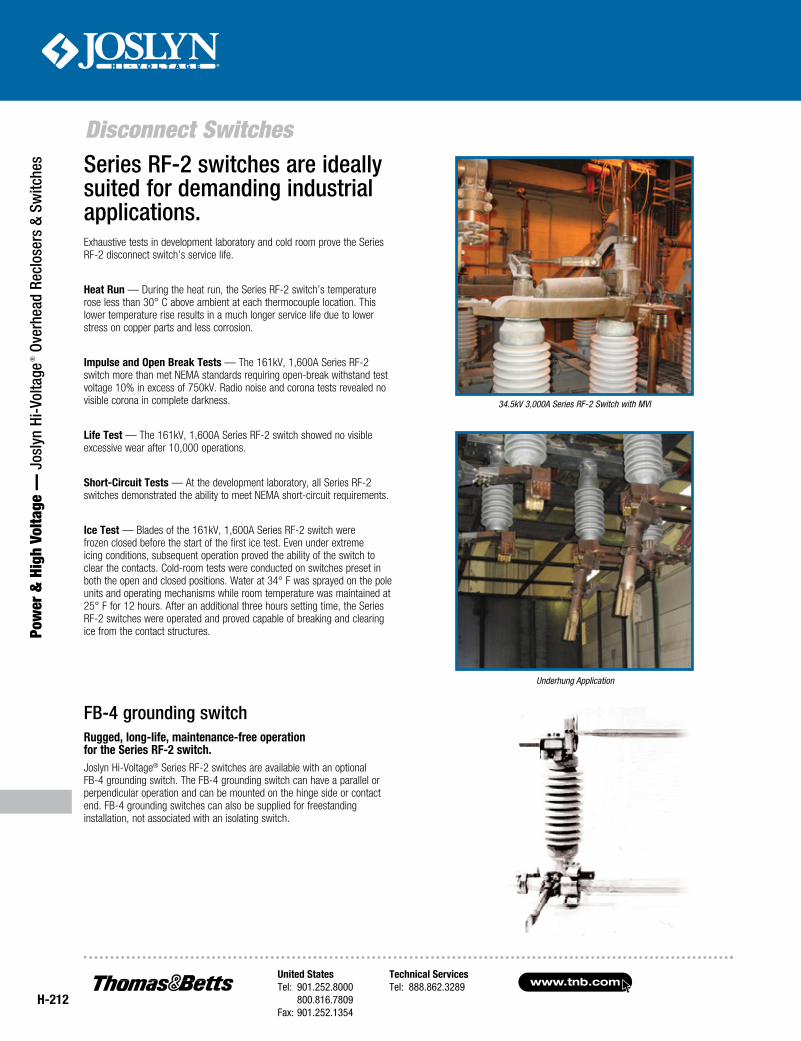
Exhaustive tests in development laboratory and cold room prove the Series RF-2 disconnect switch’s service life.
Heat Run — During the heat run, the Series RF-2 switch’s temperature rose less than 30° C above ambient at each thermocouple location. This lower temperature rise results in a much longer service life due to lower stress on copper parts and less corrosion.
Impulse and Open Break Tests — The 161kV, 1,600A Series RF-2 switch more than met NEMA standards requiring open-break withstand test voltage 10% in excess of 750kV. Radio noise and corona tests revealed no visible corona in complete darkness.
Life Test — The 161kV, 1,600A Series RF-2 switch showed no visible excessive wear after 10,000 operations.
Short-Circuit Tests — At the development laboratory, all Series RF-2 switches demonstrated the ability to meet NEMA short-circuit requirements.
Ice Test — Blades of the 161kV, 1,600A Series RF-2 switch were frozen closed before the start of the first ice test. Even under extreme icing conditions, subsequent operation proved the ability of the switch to clear the contacts. Cold-room tests were conducted on switches preset in both the open and closed positions. Water at 34° F was sprayed on the pole units and operating mechanisms while room temperature was maintained at 25° F for 12 hours. After an additional three hours setting time, the Series RF-2 switches were operated and proved capable of breaking and clearing ice from the contact structures.
FB-4 grounding switchRugged, long-life, maintenance-free operation for the Series RF-2 switch.Joslyn Hi-Voltage® Series RF-2 switches are available with an optional FB-4 grounding switch. The FB-4 grounding switch can have a parallel or perpendicular operation and can be mounted on the hinge side or contact end. FB-4 grounding switches can also be supplied for freestanding installation, not associated with an isolating switch.
Series RF-2 switches are ideally suited for demanding industrial applications.
34.5kV 3,000A Series RF-2 Switch with MVI
Underhung Application
United StatesTel: 901.252.8000 800.816.7809Fax: 901.252.1354
Technical ServicesTel: 888.862.3289www.tnb.com
Disconnect Switches
Power &
High Voltage — Joslyn Hi-Voltage
® Overhead Reclosers & Switches
H-213
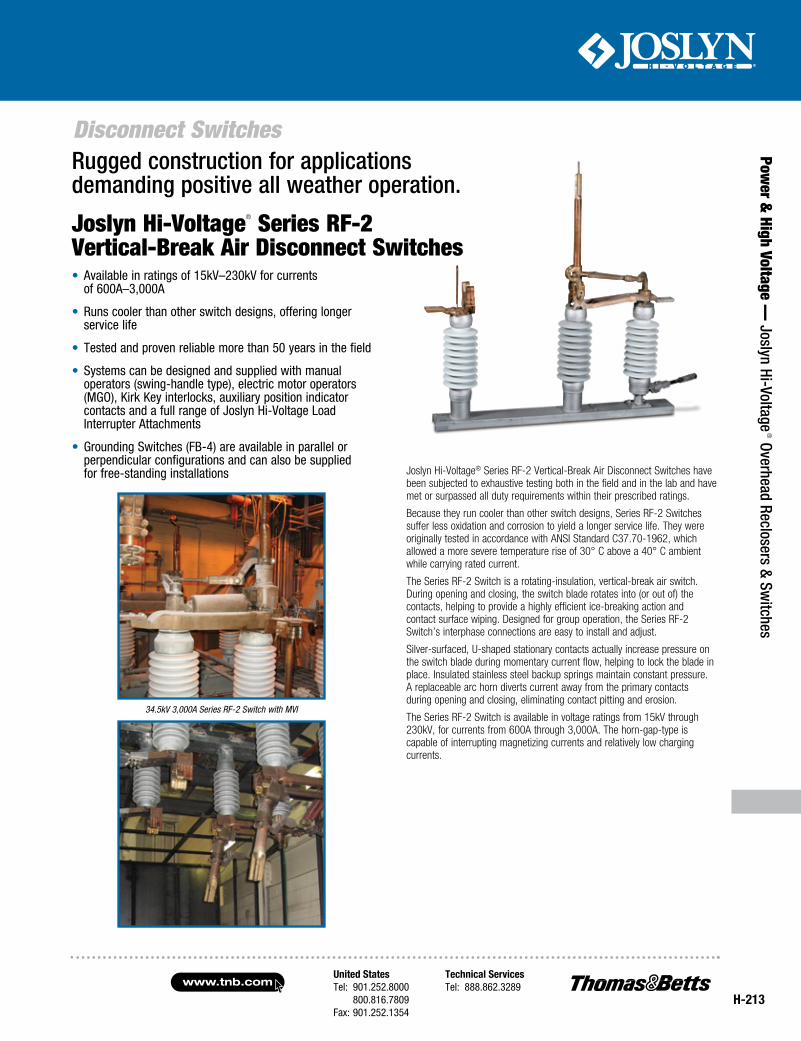
Joslyn Hi-Voltage® Series RF-2 Vertical-Break Air Disconnect Switches have been subjected to exhaustive testing both in the field and in the lab and have met or surpassed all duty requirements within their prescribed ratings.
Because they run cooler than other switch designs, Series RF-2 Switches suffer less oxidation and corrosion to yield a longer service life. They were originally tested in accordance with ANSI Standard C37.70-1962, which allowed a more severe temperature rise of 30° C above a 40° C ambient while carrying rated current.
The Series RF-2 Switch is a rotating-insulation, vertical-break air switch. During opening and closing, the switch blade rotates into (or out of) the contacts, helping to provide a highly efficient ice-breaking action and contact surface wiping. Designed for group operation, the Series RF-2 Switch’s interphase connections are easy to install and adjust.
Silver-surfaced, U-shaped stationary contacts actually increase pressure on the switch blade during momentary current flow, helping to lock the blade in place. Insulated stainless steel backup springs maintain constant pressure. A replaceable arc horn diverts current away from the primary contacts during opening and closing, eliminating contact pitting and erosion.
The Series RF-2 Switch is available in voltage ratings from 15kV through 230kV, for currents from 600A through 3,000A. The horn-gap-type is capable of interrupting magnetizing currents and relatively low charging currents.
Rugged construction for applications demanding positive all weather operation.
Joslyn Hi-Voltage® Series RF-2 Vertical-Break Air Disconnect Switches
34.5kV 3,000A Series RF-2 Switch with MVI
• Available in ratings of 15kV–230kV for currents of 600A–3,000A
• Runs cooler than other switch designs, offering longer service life
• Tested and proven reliable more than 50 years in the field
• Systems can be designed and supplied with manual operators (swing-handle type), electric motor operators (MGO), Kirk Key interlocks, auxiliary position indicator contacts and a full range of Joslyn Hi-Voltage Load Interrupter Attachments
• Grounding Switches (FB-4) are available in parallel or perpendicular configurations and can also be supplied for free-standing installations
www.tnb.comUnited StatesTel: 901.252.8000 800.816.7809Fax: 901.252.1354
Technical ServicesTel: 888.862.3289
H-214
Disconnect Switches
Pow
er &
Hig
h Vo
ltage
— J
osly
n Hi
-Vol
tage
® O
verh
ead
Recl
oser
s &
Switc
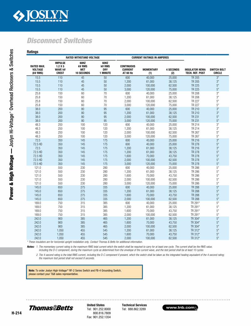
hes Ratings
Rated Max.Voltage(kV RMS)
Rated WitHStand Voltage CuRRent RatingS in aMpeReS
inSulatoR neMateCH. Ref. poSt
SWitCH BoltCiRCle
iMpulSe1.2 x 5
WaVe kVCReSt
60HzkV RMS
Wet10 SeCondS
60HzkV RMS
dRy1 Minute
ContinuouSCuRRentat 60 Hz
MoMentaRy(1)
4 SeCondS(2)
15.5 110 45 50 600 40,000 25,000 TR 205 3"15.5 110 45 50 1,200 61,000 38,125 TR 205 3"15.5 110 45 50 2,000 100,000 62,500 TR 225 5"15.5 110 45 50 3,000 120,000 75,000 TR 225 5"25.8 150 60 70 600 40,000 25,000 TR 208 3"25.8 150 60 70 1,200 61,000 38,125 TR 208 3"25.8 150 60 70 2,000 100,000 62,500 TR 227 5"25.8 150 60 70 3,000 120,000 75,000 TR 227 5"38.0 200 80 95 600 40,000 25,000 TR 210 3"38.0 200 80 95 1,200 61,000 38,125 TR 210 3"38.0 200 80 95 2,000 100,000 62,500 TR 231 5"38.0 200 80 95 3,000 120,000 75,000 TR 231 5"48.3 250 100 120 600 40,000 25,000 TR 214 3"48.3 250 100 120 1,200 61,000 38,125 TR 214 3"48.3 250 100 120 2,000 100,000 62,500 TR 267 5"48.3 250 100 120 3,000 120,000 75,000 TR 267 5"72.5 350 145 175 600 40,000 25,000 TR 216 3"
72.5 HD 350 145 175 600 40,000 25,000 TR 278 5"72.5 350 145 175 1,200 61,000 38,125 TR 216 3"
72.5 HD 350 145 175 1,200 61,000 38,125 TR 278 5"72.5 HD 350 145 175 1,600 70,000 43,750 TR 278 5"72.5 HD 350 145 175 2,000 100,000 62,500 TR 278 5"72.5 HD 350 145 175 3,000 120,000 75,000 TR 278 5"121.0 550 230 280 600 40,000 25,000 TR 286 5"121.0 550 230 280 1,200 61,000 38,125 TR 286 5"121.0 550 230 280 1,600 70,000 43,750 TR 286 5"121.0 550 230 280 2,000 100,000 62,500 TR 286 5"121.0 550 230 280 3,000 120,000 75,000 TR 286 5"145.0 650 275 335 600 40,000 25,000 TR 288 5"145.0 650 275 335 1,200 61,000 38,125 TR 288 5"145.0 650 275 335 1,600 70,000 43,750 TR 288 5"145.0 650 275 335 2,000 100,000 62,500 TR 288 5"169.0 750 315 385 600 40,000 25,000 TR 291* 5"169.0 750 315 385 1,200 61,000 38,125 TR 291* 5"169.0 750 315 385 1,600 70,000 43,750 TR 291* 5"169.0 750 315 385 2,000 100,000 62,500 TR 291* 5"242.0 900 385 465 1,200 61,000 38,125 TR 304* 5"242.0 900 385 465 1,600 70,000 43,750 TR 304* 5"242.0 900 385 465 2,000 100,000 62,500 TR 304* 5"242.0 1,050 455 545 1,200 61,000 38,125 TR 312* 5"242.0 1,050 455 545 1,600 70,000 43,750 TR 312* 5"242.0 1,050 455 545 2,000 100,000 62,500 TR 312* 5"
* These insulators are for horizontal upright installation only. Contact Thomas & Betts for additional information.
Notes: 1. The momentary current rating is the maximum RMS total current which the switch shall be required to carry for at least one cycle. The current shall be the RMS value, including the D-C component, during the maximum cycle as determined from the envelope of the current wave, and the test period shall be at least 10 cycles.
2. The 4-second rating is the total RMS current, including the D-C component if present, which the switch shall be taken as the integrated heating equivalent of the 4-second rating; the maximum test period shall not exceed 8 seconds.
note: To order Joslyn High-Voltage ® RF-2 Series Switch and FB-4 Grounding Switch, please contact your T&B sales representative.
United StatesTel: 901.252.8000 800.816.7809Fax: 901.252.1354
Technical ServicesTel: 888.862.3289www.tnb.com
Disconnect Switches
Power &
High Voltage — Joslyn Hi-Voltage
® Overhead Reclosers & Switches
H-215
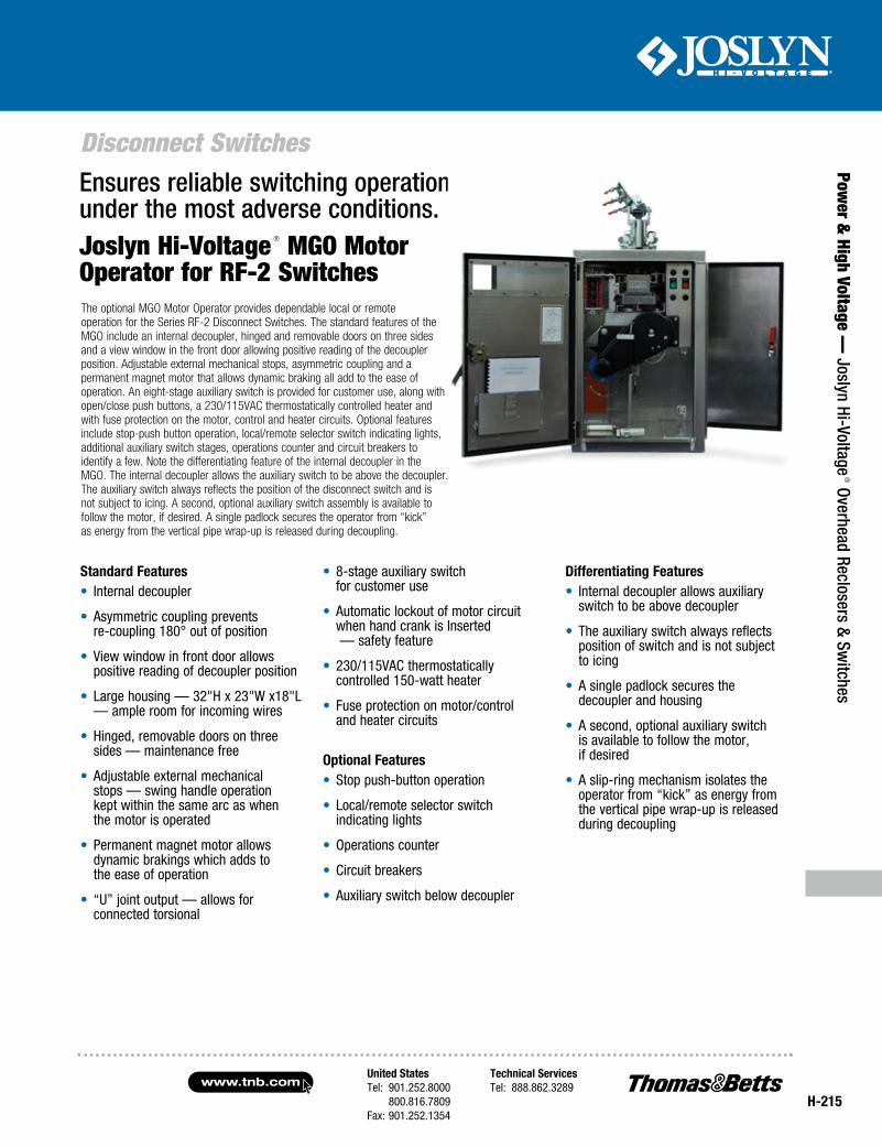
The optional MGO Motor Operator provides dependable local or remote operation for the Series RF-2 Disconnect Switches. The standard features of the MGO include an internal decoupler, hinged and removable doors on three sides and a view window in the front door allowing positive reading of the decoupler position. Adjustable external mechanical stops, asymmetric coupling and a permanent magnet motor that allows dynamic braking all add to the ease of operation. An eight-stage auxiliary switch is provided for customer use, along with open/close push buttons, a 230/115VAC thermostatically controlled heater and with fuse protection on the motor, control and heater circuits. Optional features include stop-push button operation, local/remote selector switch indicating lights, additional auxiliary switch stages, operations counter and circuit breakers to identify a few. Note the differentiating feature of the internal decoupler in the MGO. The internal decoupler allows the auxiliary switch to be above the decoupler. The auxiliary switch always reflects the position of the disconnect switch and is not subject to icing. A second, optional auxiliary switch assembly is available to follow the motor, if desired. A single padlock secures the operator from “kick” as energy from the vertical pipe wrap-up is released during decoupling.
Ensures reliable switching operation under the most adverse conditions.
Standard features• Internal decoupler
• Asymmetric coupling prevents re-coupling 180° out of position
• View window in front door allows positive reading of decoupler position
• Large housing — 32"H x 23"W x18"L — ample room for incoming wires
• Hinged, removable doors on three sides — maintenance free
• Adjustable external mechanical stops — swing handle operation kept within the same arc as when the motor is operated
• Permanent magnet motor allows dynamic brakings which adds to the ease of operation
• “U” joint output — allows for connected torsional
• 8-stage auxiliary switch for customer use
• Automatic lockout of motor circuit when hand crank is Inserted — safety feature
• 230/115VAC thermostatically controlled 150-watt heater
• Fuse protection on motor/control and heater circuits
optional features• Stop push-button operation
• Local/remote selector switch indicating lights
• Operations counter
• Circuit breakers
• Auxiliary switch below decoupler
differentiating features• Internal decoupler allows auxiliary
switch to be above decoupler
• The auxiliary switch always reflects position of switch and is not subject to icing
• A single padlock secures the decoupler and housing
• A second, optional auxiliary switch is available to follow the motor, if desired
• A slip-ring mechanism isolates the operator from “kick” as energy from the vertical pipe wrap-up is released during decoupling
Joslyn Hi-Voltage ® MGO Motor Operator for RF-2 Switches
www.tnb.comUnited StatesTel: 901.252.8000 800.816.7809Fax: 901.252.1354
Technical ServicesTel: 888.862.3289
H-216
Disconnect Switches
Pow
er &
Hig
h Vo
ltage
— J
osly
n Hi
-Vol
tage
® O
verh
ead
Recl
oser
s &
Switc
hes
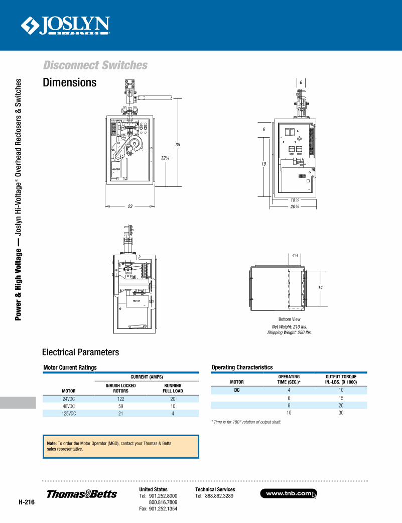
Electrical Parameters
Motor Current Ratings
MOTOR
CURRENT (AMPS)
INRUSH LOCKEDROTORS
RUNNINGFULL LOAD
24VDC 122 2048VDC 59 10
125VDC 21 4
Operating Characteristics
MOTOROPERATING TIME (SEC.)*
OUTPUT TORQUE IN.-LBS. (x 1000)
DC 4 10
6 158 2010 30
* Time is for 180° rotation of output shaft.
23
32 1⁄8
38
4 1⁄2
14
Net Weight: 210 lbs.Shipping Weight: 250 lbs.
Bottom View
18 1⁄220 3⁄8
6
6
19
Dimensions
Note: To order the Motor Operator (MGO), contact your Thomas & Betts sales representative.
United StatesTel: 901.252.8000 800.816.7809Fax: 901.252.1354
Technical ServicesTel: 888.862.3289www.tnb.com
Disconnect Switches
Power &
High Voltage — Joslyn Hi-Voltage
® Overhead Reclosers & Switches
H-217
Joslyn Hi-Voltage® Series RB-1 Side-Break Disconnect Switches provide affordable, reliable and time-proven isolating of power circuit breakers, sectionalizing of transmission lines and opening primaries of transformer banks from 15kV through 115kV.
Featuring braidless side-break construction, Series RB-1 Switches yield long, trouble-free service life with silver-to-silver, constant-pressure contacts. Low-gradient compression springs create constant pressure for the contact shoes within the main contact. The full-floating shoes allow for variations in blade alignment, are self-adjusting and wipe the blade clean with every operation of the switch. High-density silver contact surfaces minimize wear and lengthen the life of the contacts.
Series RB-1 Switches offer installation flexibility with their ability to mount in a horizontal, vertical or underhung position. Space requirements are minimized by the side-break opening. The operating mechanism can be located at various positions. One pole of a three-pole switch has an adjustable crank, permitting easy installation.
Modern power systems demand highly dependable equipment, and Series RB-1 Switches are designed, tested and proven over years in the field to yield maximum reliability and service.
In a series of cold-room tests, the Series RB-1 Switch demonstrated complete ice-breaking action. Cold-room tests were conducted on switches preset in both open and closed positions. Water was sprayed on the pole units until a 3⁄4" thick coating of clear ice formed. The switches were operated and proved capable of breaking and clearing ice from the contact structures.
Joslyn Hi-Voltage® Series RB-1 Side-Break Disconnect Switches
• Available in ratings of 15kV–115kV for currents of 600A–1,200A
• Ability to be mounted vertically, horizontally or in an underhung position offers installation flexibility; side-break opening minimizes space requirements
• One pole of the three-pole switch features an adjustable crank to permit easy installation
• Silver-to-silver constant-pressure contacts provide long, trouble-free service life
• Fully tested to NEMA and ASA standards — meets or exceeds all industry requirements, ensuring maximum reliability and service
• Systems can be designed and supplied with manual operators (swing-handle type), electric motor operators (MGO), Kirk Key interlocks, auxiliary position indicator contacts and a full range of Joslyn Hi-Voltage ® Load Interrupter Attachments
The copper solution for isolating and sectionalizing your service.
Terminal Pad
Contact BarContact-Pressure Springs
Contact-Pressure Springs
Blade End
Contact Shoes
Contact Support
www.tnb.comUnited StatesTel: 901.252.8000 800.816.7809Fax: 901.252.1354
Technical ServicesTel: 888.862.3289
H-218
Disconnect Switches
Pow
er &
Hig
h Vo
ltage
— J
osly
n Hi
-Vol
tage
® O
verh
ead
Recl
oser
s &
Switc
hes
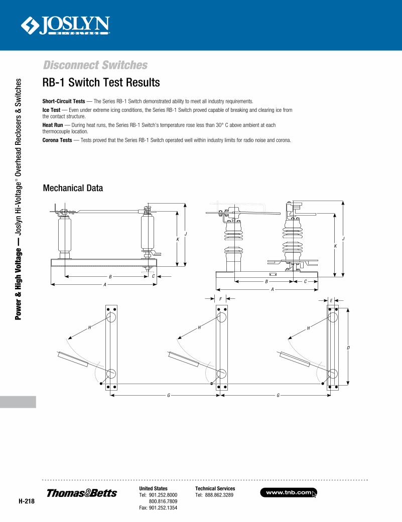
Short-Circuit Tests — The Series RB-1 Switch demonstrated ability to meet all industry requirements.
Ice Test — Even under extreme icing conditions, the Series RB-1 Switch proved capable of breaking and clearing ice from the contact structure.
Heat Run — During heat runs, the Series RB-1 Switch’s temperature rose less than 30° C above ambient at each thermocouple location.
Corona Tests — Tests proved that the Series RB-1 Switch operated well within industry limits for radio noise and corona.
RB-1 Switch Test Results
Mechanical Data
G
HHH
D
F E
G
J
K
JK
CBB
AA
C
United StatesTel: 901.252.8000 800.816.7809Fax: 901.252.1354
Technical ServicesTel: 888.862.3289www.tnb.com
Disconnect Switches
Power &
High Voltage — Joslyn Hi-Voltage
® Overhead Reclosers & Switches
H-219
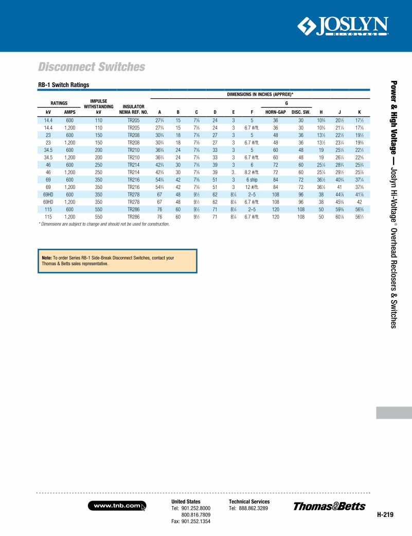
RB-1 Switch Ratings
ImpulSeWITHSTandIng
kVInSulaToR
nema Ref. no.
dImenSIonS In InCHeS (appRox)*
RaTIngS
a B C d e f
g
H j kkV ampS HoRn-gap dISC. SW.
14.4 600 110 TR205 273⁄4 15 73⁄8 24 3 5 36 30 103⁄4 201⁄2 171⁄214.4 1,200 110 TR205 273⁄4 15 73⁄8 24 3 6.7 #/ft. 36 30 103⁄4 211⁄4 175⁄823 600 150 TR208 303⁄4 18 73⁄8 27 3 5 48 36 131⁄2 221⁄2 191⁄223 1,200 150 TR208 303⁄4 18 73⁄8 27 3 6.7 #/ft. 48 36 131⁄2 231⁄4 195⁄8
34.5 600 200 TR210 363⁄4 24 73⁄8 33 3 5 60 48 19 251⁄2 221⁄234.5 1,200 200 TR210 363⁄4 24 73⁄8 33 3 6.7 #/ft. 60 48 19 261⁄4 225⁄846 600 250 TR214 423⁄4 30 73⁄8 39 3 6 72 60 251⁄4 283⁄4 253⁄446 1,200 250 TR214 423⁄4 30 73⁄8 39 3. 8.2 #/ft. 72 60 251⁄4 291⁄2 257⁄869 600 350 TR216 543⁄4 42 73⁄8 51 3 6 ship 84 72 361⁄2 403⁄4 371⁄469 1,200 350 TR216 543⁄4 42 73⁄8 51 3 12 #/ft. 84 72 361⁄2 41 373⁄8
69HD 600 350 TR278 67 48 91⁄2 62 81⁄4 2–5 108 96 38 447⁄8 417⁄8
69HD 1,200 350 TR278 67 48 91⁄2 62 81⁄4 6.7 #/ft. 108 96 38 455⁄8 42115 600 550 TR286 76 60 91⁄2 71 81⁄4 2–5 120 108 50 593⁄8 563⁄8115 1,200 550 TR286 76 60 91⁄2 71 81⁄4 6.7 #/ft. 120 108 50 601⁄8 561⁄2
* Dimensions are subject to change and should not be used for construction.
note: To order Series RB-1 Side-Break Disconnect Switches, contact your Thomas & Betts sales representative.
www.tnb.comUnited StatesTel: 901.252.8000 800.816.7809Fax: 901.252.1354
Technical ServicesTel: 888.862.3289
H-220
Load Interrupter Attachments
Pow
er &
Hig
h Vo
ltage
— J
osly
n Hi
-Vol
tage
® O
verh
ead
Recl
oser
s &
Switc
hes
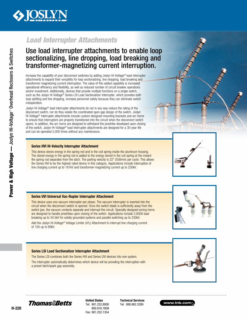
Series HVI Hi-Velocity Interrupter AttachmentThis device stores energy in the spring rod and in the coil spring inside the aluminum housing. The stored energy in the spring rod is added to the energy stored in the coil spring at the instant the spring rod separates from the latch. The parting velocity is 22" (558mm) per cycle. This allows the Series HVI to be the highest rated device in this category. Applications include interruption of line charging current up to 161kV and transformer-magnetizing current up to 230kV.
Series UVI Universal Vac-Rupter Interrupter AttachmentThis device uses one vacuum interrupter per phase. The vacuum interrupter is inserted into the circuit when the disconnect switch is opened. Once the switch blade is sufficiently away from the switch jaw, the vacuum contacts separate and interrupt the circuit. Specially designed arcing horns are designed to handle prestrikes upon closing of the switch. Applications include 2,000A load breaking up to 34.5kV for solidly grounded systems and parallel switching up to 230kV.
Add the Joslyn Hi-Voltage® Voltage Limiter (V/L) Attachment to interrupt line charging current of 15A up to 69kV.
Series LSI Load Sectionalizer Interrupter AttachmentThe Series LSI combines both the Series HVI and Series UVI devices into one system.
The interrupter automatically determines which device will be providing the interruption with a preset latch/spark gap assembly.
Increase the capability of your disconnect switches by adding Joslyn Hi-Voltage® load interrupter attachments to expand their versatility for loop sectionalizing, line dropping, load breaking and transformer-magnetizing current interruption. The value of this added capability is increased operational efficiency and flexibility, as well as reduced number of circuit breaker operations and/or investment. Additionally, devices that provide multiple functions on a single switch, such as the Joslyn Hi-Voltage® Series LSI Load Sectionalizer Interrupter, which provides both loop splitting and line dropping, increase personnel safety because they can eliminate switch misoperation.
Joslyn Hi-Voltage® load interrupter attachments do not in any way reduce the rating of the disconnect switch, nor do they violate the coordinated open gap design of the switch. Joslyn Hi-Voltage® interrupter attachments include custom-designed mounting brackets and arc horns to ensure that interrupters are properly transitioned into the circuit when the disconnect switch opens. In addition, the arc horns are designed to withstand the prestrike developed upon closing of the switch. Joslyn Hi-Voltage® load interrupter attachments are designed for a 30-year life and can be operated 5,000 times without any maintenance.
Use load interrupter attachments to enable loop sectionalizing, line dropping, load breaking and transformer-magnetizing current interruption.
United StatesTel: 901.252.8000 800.816.7809Fax: 901.252.1354
Technical ServicesTel: 888.862.3289www.tnb.com
H-221
Load Interrupter Attachments
Power &
High Voltage — Joslyn Hi-Voltage
® Overhead Reclosers & Switches
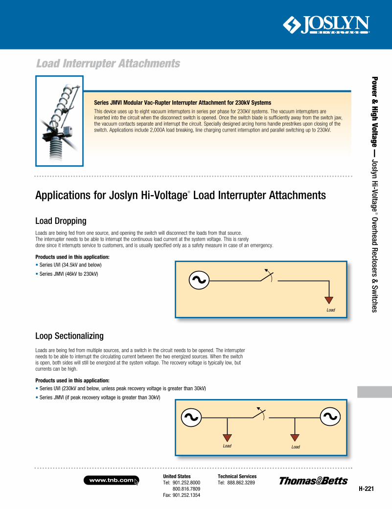
Series JMVI Modular Vac-Rupter Interrupter Attachment for 230kV SystemsThis device uses up to eight vacuum interrupters in series per phase for 230kV systems. The vacuum interrupters are inserted into the circuit when the disconnect switch is opened. Once the switch blade is sufficiently away from the switch jaw, the vacuum contacts separate and interrupt the circuit. Specially designed arcing horns handle prestrikes upon closing of the switch. Applications include 2,000A load breaking, line charging current interruption and parallel switching up to 230kV.
Load Dropping Loads are being fed from one source, and opening the switch will disconnect the loads from that source. The interrupter needs to be able to interrupt the continuous load current at the system voltage. This is rarely done since it interrupts service to customers, and is usually specified only as a safety measure in case of an emergency.
Products used in this application: • Series UVI (34.5kV and below)
• Series JMVI (46kV to 230kV)
Applications for Joslyn Hi-Voltage® Load Interrupter Attachments
Loop SectionalizingLoads are being fed from multiple sources, and a switch in the circuit needs to be opened. The interrupter needs to be able to interrupt the circulating current between the two energized sources. When the switch is open, both sides will still be energized at the system voltage. The recovery voltage is typically low, but currents can be high.
Products used in this application: • Series UVI (230kV and below, unless peak recovery voltage is greater than 30kV)
• Series JMVI (if peak recovery voltage is greater than 30kV)
Load Load
Load
www.tnb.comUnited StatesTel: 901.252.8000 800.816.7809Fax: 901.252.1354
Technical ServicesTel: 888.862.3289
H-222
Load Interrupter Attachments
Pow
er &
Hig
h Vo
ltage
— J
osly
n Hi
-Vol
tage
® O
verh
ead
Recl
oser
s &
Switc
hes
Transformer-Magnetizing CurrentWhen a transformer is energized and no load is connected to it, a small amount of current still flows. This current is called transformer-magnetizing current. When the transformer is de-energized, the recovery voltage will be high, because the system voltage will be seen on the source side of the switch and a charge will be trapped on the other side of the switch.
Products used in this application:
• Series UVI (34.5kV and below; up to 69kV with Voltage Limiter)
• Series HVI (69kV to 230kV)
Underground CableMany factors determine the amount of cable charging current, such as the cable insulation material and geometry of the conductors. A common guideline for determining the charging current is to use 1.5A per 1,000 ft. of cable; however, it is always recommended to contact the cable manufacturer to obtain the exact charging current for a particular cable.
Typical Conductor and Cable Charging CurrentsOverhead Conductor
SyStem VOltage (kV) typiCal CHarging CUrrent per mile (a)
69 .226 115 .377 138 .440 161 .502 230 .737
Line and Cable Dropping When a section of line is energized and no load is connected, a small amount of charging current is flowing. When the line is de-energized, the recovery voltage will be high, because the system voltage will be seen on the source side of the switch and a charge will be trapped on the other side of the switch.
Products used in this application:
• Series UVI (34.5kV and below; up to 69kV with Voltage Limiter)
• Series HVI (69kV to 161kV)
• Series JMVI (230kV and below)
transformer general reference information*SyStem VOltage (kV) tranSfOrmer mVa magnetizing CUrrent per pHaSe fUll lOad CUrrent (%)
6910 2.6 3.1 25 5.0 2.4
13810 .98 2.4 25 3.2 3.1 50 6.5 3.1
161 25 3.5 3.9 50 7.0 3.9
230 25 2.2 3.5 50 3.5 2.8
* Transmission & Distribution — Westinghouse Electric Corp., Fifth Edition, 1964
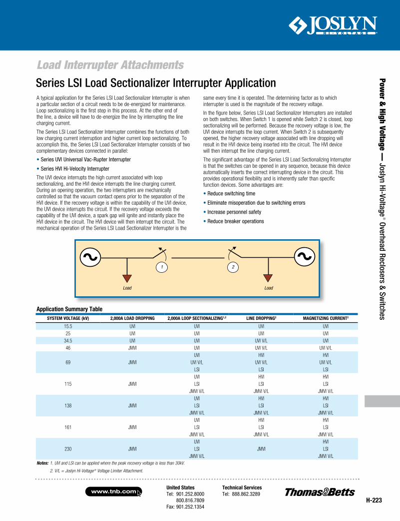
United StatesTel: 901.252.8000 800.816.7809Fax: 901.252.1354
Technical ServicesTel: 888.862.3289www.tnb.com
H-223
Load Interrupter Attachments
Power &
High Voltage — Joslyn Hi-Voltage
® Overhead Reclosers & Switches
A typical application for the Series LSI Load Sectionalizer Interrupter is when a particular section of a circuit needs to be de-energized for maintenance. Loop sectionalizing is the first step in this process. At the other end of the line, a device will have to de-energize the line by interrupting the line charging current.
The Series LSI Load Sectionalizer Interrupter combines the functions of both low charging current interruption and higher current loop sectionalizing. To accomplish this, the Series LSI Load Sectionalizer Interrupter consists of two complementary devices connected in parallel:
• Series UVI Universal Vac-Rupter Interrupter
• Series HVI Hi-Velocity Interrupter
The UVI device interrupts the high current associated with loop sectionalizing, and the HVI device interrupts the line charging current. During an opening operation, the two interrupters are mechanically controlled so that the vacuum contact opens prior to the separation of the HVI device. If the recovery voltage is within the capability of the UVI device, the UVI device interrupts the circuit. If the recovery voltage exceeds the capability of the UVI device, a spark gap will ignite and instantly place the HVI device in the circuit. The HVI device will then interrupt the circuit. The mechanical operation of the Series LSI Load Sectionalizer Interrupter is the
application Summary tableSyStem VOltage (kV) 2,000a lOad drOpping 2,000a lOOp SeCtiOnalizing1,2 line drOpping2 magnetizing CUrrent2
15.5 UVI UVI UVI UVI 25 UVI UVI UVI UVI
34.5 UVI UVI UVI V/L UVI 46 JMVI UVI UVI V/L UVI V/L
UVI HVI HVI69 JMVI UVI V/L UVI V/L UVI V/L
LSI LSI LSI UVI HVI HVI
115 JMVI LSI LSI LSIJMVI V/L JMVI V/L JMVI V/L
UVI HVI HVI138 JMVI LSI LSI LSI
JMVI V/L JMVI V/L JMVI V/LUVI HVI HVI
161 JMVI LSI LSI LSIJMVI V/L JMVI V/L JMVI V/L
UVI HVI230 JMVI LSI JMVI LSI
JMVI V/L JMVI V/L Notes: 1. UVI and LSI can be applied where the peak recovery voltage is less than 30kV.
2. V/L = Joslyn Hi-Voltage ® Voltage Limiter Attachment.
Load Load
1 2
Series LSI Load Sectionalizer Interrupter Applicationsame every time it is operated. The determining factor as to which interrupter is used is the magnitude of the recovery voltage.
In the figure below, Series LSI Load Sectionalizer Interrupters are installed on both switches. When Switch 1 is opened while Switch 2 is closed, loop sectionalizing will be performed. Because the recovery voltage is low, the UVI device interrupts the loop current. When Switch 2 is subsequently opened, the higher recovery voltage associated with line dropping will result in the HVI device being inserted into the circuit. The HVI device will then interrupt the line charging current.
The significant advantage of the Series LSI Load Sectionalizing Interrupter is that the switches can be opened in any sequence, because this device automatically inserts the correct interrupting device in the circuit. This provides operational flexibility and is inherently safer than specific function devices. Some advantages are:
• Reduce switching time
• Eliminate misoperation due to switching errors
• Increase personnel safety
• Reduce breaker operations
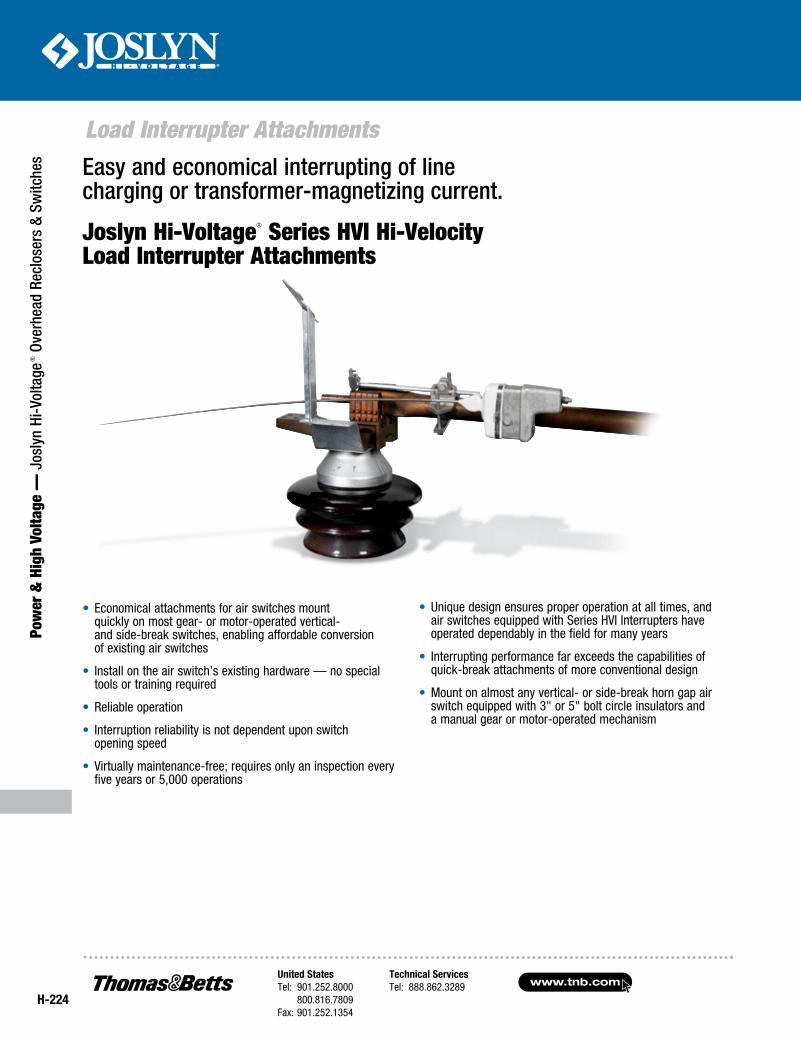
www.tnb.comUnited StatesTel: 901.252.8000 800.816.7809Fax: 901.252.1354
Technical ServicesTel: 888.862.3289
H-224
Load Interrupter Attachments
Pow
er &
Hig
h Vo
ltage
— J
osly
n Hi
-Vol
tage
® O
verh
ead
Recl
oser
s &
Switc
hes Easy and economical interrupting of line
charging or transformer-magnetizing current.
Joslyn Hi-Voltage® Series HVI Hi-Velocity Load Interrupter Attachments
• Economical attachments for air switches mount quickly on most gear- or motor-operated vertical- and side-break switches, enabling affordable conversion of existing air switches
• Install on the air switch’s existing hardware — no special tools or training required
• Reliable operation
• Interruption reliability is not dependent upon switch opening speed
• Virtually maintenance-free; requires only an inspection every five years or 5,000 operations
• Unique design ensures proper operation at all times, and air switches equipped with Series HVI Interrupters have operated dependably in the field for many years
• Interrupting performance far exceeds the capabilities of quick-break attachments of more conventional design
• Mount on almost any vertical- or side-break horn gap air switch equipped with 3" or 5" bolt circle insulators and a manual gear or motor-operated mechanism
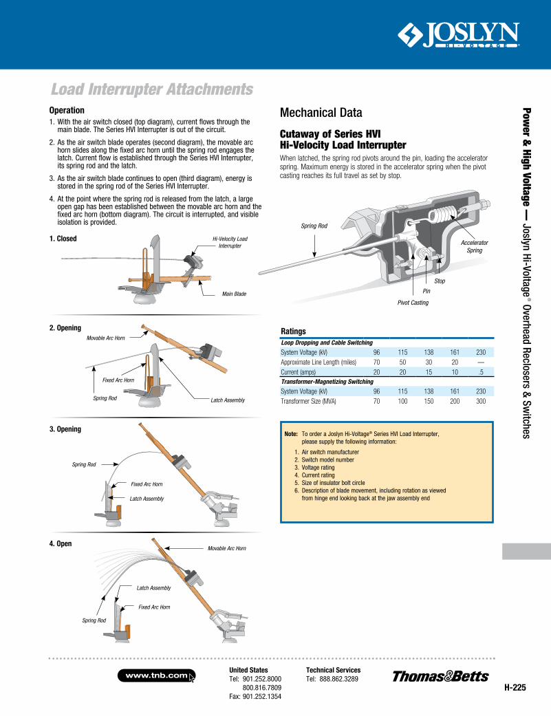
United StatesTel: 901.252.8000 800.816.7809Fax: 901.252.1354
Technical ServicesTel: 888.862.3289www.tnb.com
H-225
Load Interrupter Attachments
Power &
High Voltage — Joslyn Hi-Voltage
® Overhead Reclosers & Switches
Main Blade
Hi-Velocity Load Interrupter
Mechanical Data
Cutaway of Series HVI Hi-Velocity Load Interrupter When latched, the spring rod pivots around the pin, loading the accelerator spring. Maximum energy is stored in the accelerator spring when the pivot casting reaches its full travel as set by stop.
Note: To order a Joslyn Hi-Voltage® Series HVI Load Interrupter, please supply the following information:
1. Air switch manufacturer 2. Switch model number 3. Voltage rating 4. Current rating 5. Size of insulator bolt circle 6. Description of blade movement, including rotation as viewed from hinge end looking back at the jaw assembly end
RatingsLoop Dropping and Cable Switching
System Voltage (kV) 96 115 138 161 230Approximate Line Length (miles) 70 50 30 20 —Current (amps) 20 20 15 10 .5Transformer-Magnetizing Switching
System Voltage (kV) 96 115 138 161 230Transformer Size (MVA) 70 100 150 200 300
Operation1. With the air switch closed (top diagram), current flows through the
main blade. The Series HVI Interrupter is out of the circuit.
2. As the air switch blade operates (second diagram), the movable arc horn slides along the fixed arc horn until the spring rod engages the latch. Current flow is established through the Series HVI Interrupter, its spring rod and the latch.
3. As the air switch blade continues to open (third diagram), energy is stored in the spring rod of the Series HVI Interrupter.
4. At the point where the spring rod is released from the latch, a large open gap has been established between the movable arc horn and the fixed arc horn (bottom diagram). The circuit is interrupted, and visible isolation is provided.
3. Opening
4. Open
Fixed Arc Horn
Latch Assembly
Spring Rod
Fixed Arc Horn
Latch Assembly
Movable Arc Horn
Spring Rod
1. Closed
2. OpeningMovable Arc Horn
Latch AssemblySpring Rod
Fixed Arc Horn
Spring Rod
Pivot Casting
Pin
Stop
Accelerator Spring
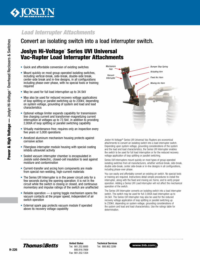
www.tnb.comUnited StatesTel: 901.252.8000 800.816.7809Fax: 901.252.1354
Technical ServicesTel: 888.862.3289
H-226
Load Interrupter Attachments
Pow
er &
Hig
h Vo
ltage
— J
osly
n Hi
-Vol
tage
® O
verh
ead
Recl
oser
s &
Switc
hes
Joslyn Hi-Voltage® Series UVI Universal Vac-Rupters are economical attachments to convert an isolating switch into a load interrupter switch. Depending upon system voltage, grounding considerations of the system and the load and load characteristics, the Series UVI Interrupter enables the switch to be used for full load interruption or for the reduced recovery voltage application of loop splitting or parallel switching.
Series UVI Interrupters mount quickly on most types of group-operated isolating switches from all manufacturers, whether vertical-break, side-break, double side-break, center side-break or in-line designs in all configurations, including phase-over-phase.
You can easily and affordably convert an existing air switch. No special tools or training are required. Instructions detail simple procedures to install the interrupter, along with the fixed and moving arc horns, and to verify proper operation. Adding a Series UVI Load Interrupter will not affect the mechanical operation of the switch.
The Series UVI Interrupter converts an isolating switch into a load interrupter switch. The switch may be used for full 2,000A load interruption up to 34.5kV. The Series UVI Interrupter may also be used for the reduced recovery voltage application of loop splitting or parallel switching up to 230kV, depending on system voltage, grounding considerations of the system and load and load characteristics. Use the ratings table for determination.
Convert an isolating switch into a load interrupter switch.
Joslyn Hi-Voltage® Series UVI Universal Vac-Rupter Load Interrupter Attachments
MechanismHub
Bumper Stop Spring
Actuating Arm
Fixed Arc HornVacuum
Interrupter
Moving Arc Horn
• Quick and affordable conversion of existing switches
• Mount quickly on most group-operated isolating switches, including vertical-break, side-break, double-side break, center-side break and in-line designs, in all configurations including phase-over-phase, with no special tools or training required
• May be used for full load interruption up to 34.5kV
• May also be used for reduced recovery voltage applications of loop splitting or parallel switching up to 230kV, depending on system voltage, grounding of system and load and load characteristics
• Optional voltage limiter expands capability for transmission line charging current and transformer-magnetizing current interruption at voltages up to 72.5kV, in addition to providing 2,000A of loop splitting or parallel switching capability
• Virtually maintenance-free; requires only an inspection every five years or 5,000 operations
• Anodized aluminum mechanism housing protects against corrosive action
• Fiberglass interrupter module housing with special coating inhibits ultraviolet activity
• Sealed vacuum interrupter chamber is encapsulated in Joslyte solid-dielectric, closed-cell insulation to seal against moisture and contamination
• Current-transfer and arcing horn components are made from special non-welding, high-current materials
• The Series UVI Interrupter is in the power circuit only for a few seconds during the opening operation; it is not in the circuit while the switch is closing or closed, and continuous momentary and impulse ratings of the switch are unaffected
• Reliable operation — a spring toggle mechanism opens the vacuum contacts at the proper speed, independent of air switch operation
• External spark gap protects vacuum module if operated above its recovery voltage capability
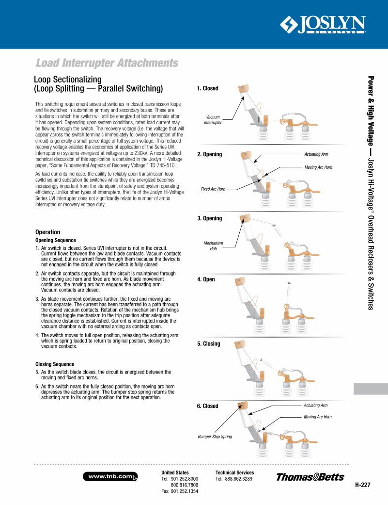
United StatesTel: 901.252.8000 800.816.7809Fax: 901.252.1354
Technical ServicesTel: 888.862.3289www.tnb.com
H-227
Load Interrupter Attachments
Power &
High Voltage — Joslyn Hi-Voltage
® Overhead Reclosers & Switches
This switching requirement arises at switches in closed transmission loops and tie switches in substation primary and secondary buses. These are situations in which the switch will still be energized at both terminals after it has opened. Depending upon system conditions, rated load current may be flowing through the switch. The recovery voltage (i.e. the voltage that will appear across the switch terminals immediately following interruption of the circuit) is generally a small percentage of full system voltage. This reduced recovery voltage enables the economics of application of the Series UVI Interrupter on systems energized at voltages up to 230kV. A more detailed technical discussion of this application is contained in the Joslyn Hi-Voltage paper, “Some Fundamental Aspects of Recovery Voltage,” TD 745-510.
As load currents increase, the ability to reliably open transmission loop switches and substation tie switches while they are energized becomes increasingly important from the standpoint of safety and system operating efficiency. Unlike other types of interrupters, the life of the Joslyn Hi-Voltage Series UVI Interrupter does not significantly relate to number of amps interrupted or recovery voltage duty.
OperationOpening Sequence1. Air switch is closed. Series UVI Interrupter is not in the circuit.
Current flows between the jaw and blade contacts. Vacuum contacts are closed, but no current flows through them because the device is not engaged in the circuit when the switch is fully closed.
2. Air switch contacts separate, but the circuit is maintained through the moving arc horn and fixed arc horn. As blade movement continues, the moving arc horn engages the actuating arm. Vacuum contacts are closed.
3. As blade movement continues farther, the fixed and moving arc horns separate. The current has been transferred to a path through the closed vacuum contacts. Rotation of the mechanism hub brings the spring toggle mechanism to the trip position after adequate clearance distance is established. Current is interrupted inside the vacuum chamber with no external arcing as contacts open.
4. The switch moves to full open position, releasing the actuating arm, which is spring loaded to return to original position, closing the vacuum contacts.
Closing Sequence5. As the switch blade closes, the circuit is energized between the
moving and fixed arc horns.
6. As the switch nears the fully closed position, the moving arc horn depresses the actuating arm. The bumper stop spring returns the actuating arm to its original position for the next operation.
Actuating Arm
Moving Arc Horn
Fixed Arc Horn
Mechanism Hub
Actuating Arm
Moving Arc Horn
Bumper Stop Spring
1. Closed
2. Opening
3. Opening
4. Open
5. Closing
6. Closed
Vacuum Interrupter
Loop Sectionalizing (Loop Splitting — Parallel Switching)
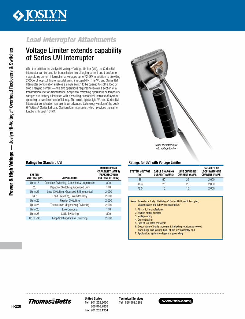
www.tnb.comUnited StatesTel: 901.252.8000 800.816.7809Fax: 901.252.1354
Technical ServicesTel: 888.862.3289
H-228
Load Interrupter Attachments
Pow
er &
Hig
h Vo
ltage
— J
osly
n Hi
-Vol
tage
® O
verh
ead
Recl
oser
s &
Switc
hes Voltage Limiter extends capability
of Series UVI InterrupterWith the addition the Joslyn Hi-Voltage® Voltage Limiter (V/L), the Series UVI Interrupter can be used for transmission line charging current and transformer-magnetizing current interruption at voltages up to 72.5kV in addition to providing 2,000A of loop splitting or parallel switching capability. The V/L and Series UVI Interrupter combination enables a single switch to be opened to split a loop or drop charging current — the two operations required to isolate a section of a transmission line for maintenance. Sequential switching operations or temporary outages are thereby eliminated with a resulting economical increase of system operating convenience and efficiency. The small, lightweight V/L and Series UVI Interrupter combination represents an advanced technology version of the Joslyn Hi-Voltage® Series LSI Load Sectionalizer Interrupter, which provides the same functions through 161kV.
Series UVI Interrupter with Voltage Limiter
Ratings for Standard UVI
SyStem Voltage (kV) applIcatIon
InteRRUptIng capabIlIty (ampS)
(peak RecoVeRy Voltage of 30kV)
Up to 15 Capacitor Switching, Grounded & Ungrounded 800 25 Capacitor Switching, Grounded Only 140
Up to 25 Load Switching, Grounded & Ungrounded 2,00034.5 Load Switching, Grounded Only 2,000
Up to 25 Reactor Switching 2,000Up to 25 Transformer-Magnetizing Switching 2,000Up to 25 Line Dropping 140Up to 25 Cable Switching 800
Up to 230 Loop Splitting/Parallel Switching 2,000
Ratings for UVI with Voltage limiter
SyStem Voltage (kV)
cable cHaRgIng cURRent (ampS)
lIne cHaRgIng cURRent (ampS)
paRallel oR loop SwItcHIng cURRent (ampS)
38 50 25 2,00048.3 25 20 2,00072.5 15 15 2,000
note: To order a Joslyn Hi-Voltage® Series UVI Load Interrupter, please supply the following information:
1. Air switch manufacturer 2. Switch model number 3. Voltage rating 4. Current rating 5. Size of insulator bolt circle 6. Description of blade movement, including rotation as viewed from hinge end looking back at the jaw assembly end 7. Application, system voltage and grounding
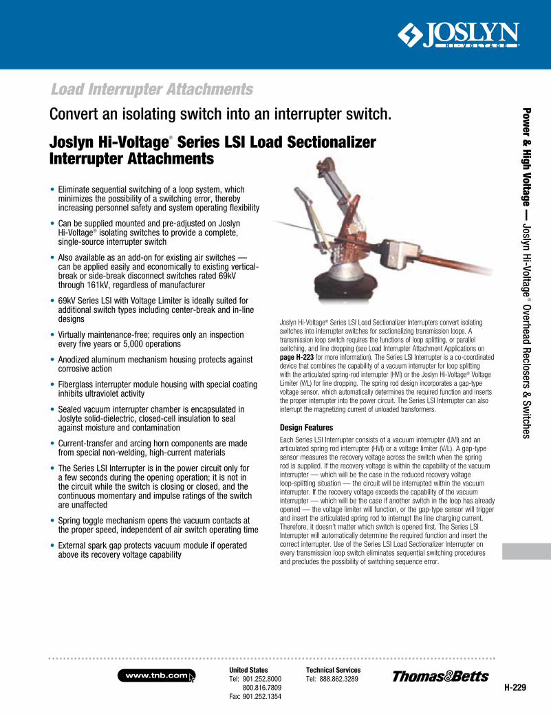
United StatesTel: 901.252.8000 800.816.7809Fax: 901.252.1354
Technical ServicesTel: 888.862.3289www.tnb.com
H-229
Load Interrupter Attachments
Power &
High Voltage — Joslyn Hi-Voltage
® Overhead Reclosers & Switches
• Eliminate sequential switching of a loop system, which minimizes the possibility of a switching error, thereby increasing personnel safety and system operating flexibility
• Can be supplied mounted and pre-adjusted on Joslyn Hi-Voltage® isolating switches to provide a complete, single-source interrupter switch
• Also available as an add-on for existing air switches — can be applied easily and economically to existing vertical-break or side-break disconnect switches rated 69kV through 161kV, regardless of manufacturer
• 69kV Series LSI with Voltage Limiter is ideally suited for additional switch types including center-break and in-line designs
• Virtually maintenance-free; requires only an inspection every five years or 5,000 operations
• Anodized aluminum mechanism housing protects against corrosive action
• Fiberglass interrupter module housing with special coating inhibits ultraviolet activity
• Sealed vacuum interrupter chamber is encapsulated in Joslyte solid-dielectric, closed-cell insulation to seal against moisture and contamination
• Current-transfer and arcing horn components are made from special non-welding, high-current materials
• The Series LSI Interrupter is in the power circuit only for a few seconds during the opening operation; it is not in the circuit while the switch is closing or closed, and the continuous momentary and impulse ratings of the switch are unaffected
• Spring toggle mechanism opens the vacuum contacts at the proper speed, independent of air switch operating time
• External spark gap protects vacuum module if operated above its recovery voltage capability
Joslyn Hi-Voltage® Series LSI Load Sectionalizer Interrupters convert isolating switches into interrupter switches for sectionalizing transmission loops. A transmission loop switch requires the functions of loop splitting, or parallel switching, and line dropping (see Load Interrupter Attachment Applications on page H-223 for more information). The Series LSI Interrupter is a co-coordinated device that combines the capability of a vacuum interrupter for loop splitting with the articulated spring-rod interrupter (HVI) or the Joslyn Hi-Voltage® Voltage Limiter (V/L) for line dropping. The spring rod design incorporates a gap-type voltage sensor, which automatically determines the required function and inserts the proper interrupter into the power circuit. The Series LSI Interrupter can also interrupt the magnetizing current of unloaded transformers.
Design featuresEach Series LSI Interrupter consists of a vacuum interrupter (UVI) and an articulated spring rod interrupter (HVI) or a voltage limiter (V/L). A gap-type sensor measures the recovery voltage across the switch when the spring rod is supplied. If the recovery voltage is within the capability of the vacuum interrupter — which will be the case in the reduced recovery voltage loop-splitting situation — the circuit will be interrupted within the vacuum interrupter. If the recovery voltage exceeds the capability of the vacuum interrupter — which will be the case if another switch in the loop has already opened — the voltage limiter will function, or the gap-type sensor will trigger and insert the articulated spring rod to interrupt the line charging current. Therefore, it doesn’t matter which switch is opened first. The Series LSI Interrupter will automatically determine the required function and insert the correct interrupter. Use of the Series LSI Load Sectionalizer Interrupter on every transmission loop switch eliminates sequential switching procedures and precludes the possibility of switching sequence error.
Convert an isolating switch into an interrupter switch.
Joslyn Hi-Voltage® Series LSI Load Sectionalizer Interrupter Attachments
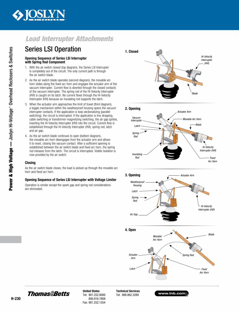
www.tnb.comUnited StatesTel: 901.252.8000 800.816.7809Fax: 901.252.1354
Technical ServicesTel: 888.862.3289
H-230
Load Interrupter Attachments
Pow
er &
Hig
h Vo
ltage
— J
osly
n Hi
-Vol
tage
® O
verh
ead
Recl
oser
s &
Switc
hes Series LSI Operation
Opening Sequence of Series LSI Interrupter with Spring Rod Component1. With the air switch closed (top diagram), the Series LSI Interrupter
is completely out of the circuit. The only current path is through the air switch blade.
2. As the air switch blade operates (second diagram), the movable arc horn slides along the fixed arc horn and engages the actuator arm of the vacuum interrupter. Current flow is diverted through the closed contacts of the vacuum interrupter. The spring rod of the Hi-Velocity Interrupter (HVI) is caught on its latch. No current flows through the Hi-Velocity Interrupter (HVI) because an insulating rod supports the latch.
3. When the actuator arm approaches the limit of travel (third diagram), a toggle mechanism within the weatherproof housing opens the vacuum interrupter contacts. If the application is loop sectionalizing (parallel switching), the circuit is interrupted. If the application is line dropping, cable switching or transformer-magnetizing switching, the air gap ignites, inserting the Hi-Velocity Interrupter (HVI) into the circuit. Current flow is established through the Hi-Velocity Interrupter (HVI), spring rod, latch and air gap.
4. As the air switch blade continues to open (bottom diagram), the movable arc horn disengages from the actuator arm and allows it to reset, closing the vacuum contact. After a sufficient opening is established between the air switch blade and fixed arc horn, the spring rod releases from the latch. The circuit is interrupted. Visible isolation is now provided by the air switch.
ClosingAs the air switch blade closes, the load is picked up through the movable arc horn and fixed arc horn.
Opening Sequence of Series LSI Interrupter with Voltage LimiterOperation is similar except the spark gap and spring rod considerations are eliminated.
1. Closed
Blade
Hi-Velocity Interrupter
(HVI)
4. OpenBlade
Fixed Arc Horn
Spring RodActuator Arm
Latch
Movable Arc Horn
3. Opening
Hi-Velocity Interrupter (HVI)
Spring Rod
Actuator Arm
Latch
Air Gap
Weatherproof Housing
2. Opening
Insulating Rod
Latch
Movable Arc HornVacuum Interrupter
Actuator Arm
Spring Rod
Hi-Velocity Interrupter (HVI)
Blade
Fixed Arc Horn
United StatesTel: 901.252.8000 800.816.7809Fax: 901.252.1354
Technical ServicesTel: 888.862.3289www.tnb.com
H-231
Load Interrupter Attachments
Power &
High Voltage — Joslyn Hi-Voltage
® Overhead Reclosers & Switches
RatingsLoop Splitting/Parallel Switching
69–230kV: Maximum interrupting current 2,000A — Maximum recovery voltage 30kV peak
Line Dropping and Cable SwitchingSystem Voltage (kV) 69 115 138 161 230Approximate Line Length (miles) 70 50 30 20 —
Current (Amps) 20 (15*) 20 15 10 .5
Transformer-Magnetizing SwitchingSystem Voltage (kV) 69 115 138 161 230Transformer Size (MVA) 70 100 150 200 300
* Rating using Voltage Limiter instead of HVI.
Note: To order a Joslyn Hi-Voltage® Series LSI Load Interrupter, please supply the following information: 1. Air switch manufacturer 2. Switch model number 3. Voltage rating 4. Current rating 5. Size of insulator bolt circle 6. Description of blade movement, including rotation as viewed from hinge end looking back at the jaw assembly end
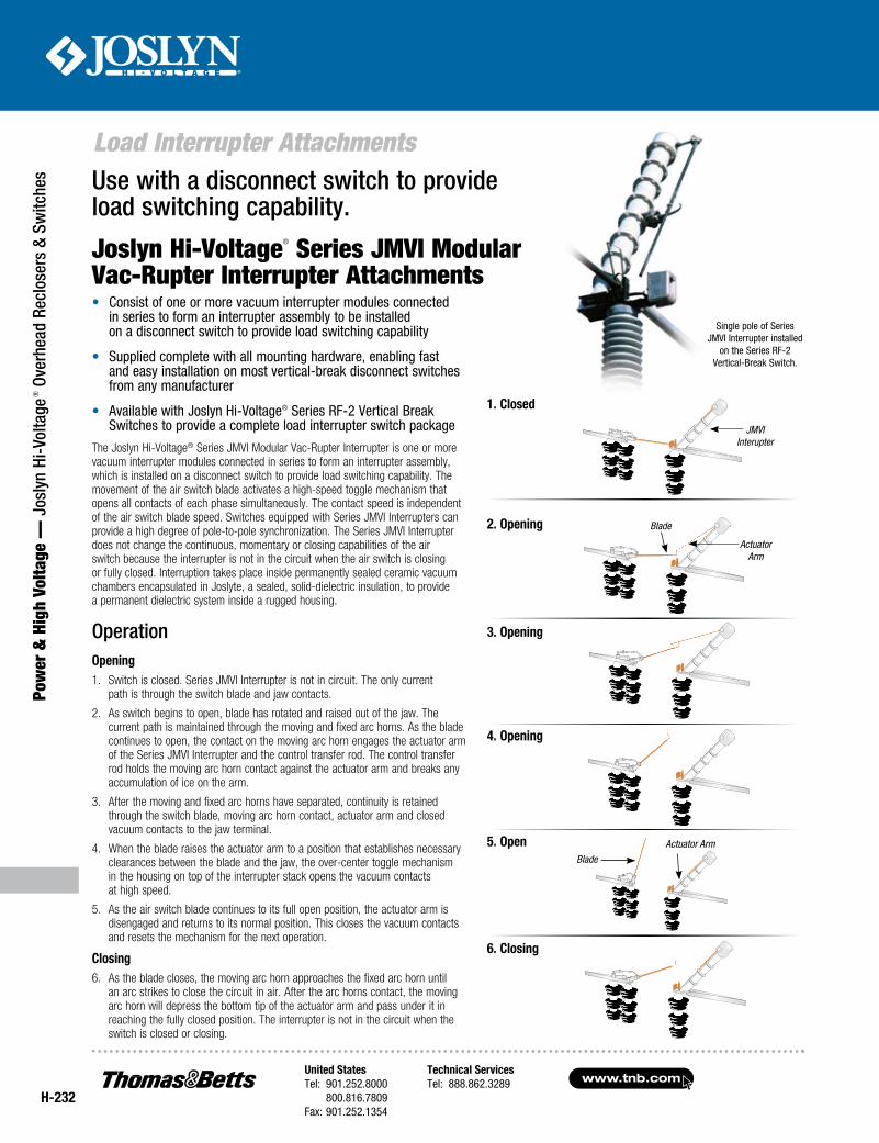
www.tnb.comUnited StatesTel: 901.252.8000 800.816.7809Fax: 901.252.1354
Technical ServicesTel: 888.862.3289
H-232
Load Interrupter Attachments
Pow
er &
Hig
h Vo
ltage
— J
osly
n Hi
-Vol
tage
® O
verh
ead
Recl
oser
s &
Switc
hes
Single pole of Series JMVI Interrupter installed
on the Series RF-2 Vertical-Break Switch.
Joslyn Hi-Voltage® Series JMVI Modular Vac-Rupter Interrupter Attachments
Use with a disconnect switch to provide load switching capability.
2. Opening
3. Opening
4. Opening
5. Open
6. Closing
1. Closed
JMVI Interupter
Actuator Arm
Blade
Actuator ArmBlade
The Joslyn Hi-Voltage® Series JMVI Modular Vac-Rupter Interrupter is one or more vacuum interrupter modules connected in series to form an interrupter assembly, which is installed on a disconnect switch to provide load switching capability. The movement of the air switch blade activates a high-speed toggle mechanism that opens all contacts of each phase simultaneously. The contact speed is independent of the air switch blade speed. Switches equipped with Series JMVI Interrupters can provide a high degree of pole-to-pole synchronization. The Series JMVI Interrupter does not change the continuous, momentary or closing capabilities of the air switch because the interrupter is not in the circuit when the air switch is closing or fully closed. Interruption takes place inside permanently sealed ceramic vacuum chambers encapsulated in Joslyte, a sealed, solid-dielectric insulation, to provide a permanent dielectric system inside a rugged housing.
OperationOpening1. Switch is closed. Series JMVI Interrupter is not in circuit. The only current
path is through the switch blade and jaw contacts.
2. As switch begins to open, blade has rotated and raised out of the jaw. The current path is maintained through the moving and fixed arc horns. As the blade continues to open, the contact on the moving arc horn engages the actuator arm of the Series JMVI Interrupter and the control transfer rod. The control transfer rod holds the moving arc horn contact against the actuator arm and breaks any accumulation of ice on the arm.
3. After the moving and fixed arc horns have separated, continuity is retained through the switch blade, moving arc horn contact, actuator arm and closed vacuum contacts to the jaw terminal.
4. When the blade raises the actuator arm to a position that establishes necessary clearances between the blade and the jaw, the over-center toggle mechanism in the housing on top of the interrupter stack opens the vacuum contacts at high speed.
5. As the air switch blade continues to its full open position, the actuator arm is disengaged and returns to its normal position. This closes the vacuum contacts and resets the mechanism for the next operation.
Closing 6. As the blade closes, the moving arc horn approaches the fixed arc horn until
an arc strikes to close the circuit in air. After the arc horns contact, the moving arc horn will depress the bottom tip of the actuator arm and pass under it in reaching the fully closed position. The interrupter is not in the circuit when the switch is closed or closing.
• Consist of one or more vacuum interrupter modules connected in series to form an interrupter assembly to be installed on a disconnect switch to provide load switching capability
• Supplied complete with all mounting hardware, enabling fast and easy installation on most vertical-break disconnect switches from any manufacturer
• Available with Joslyn Hi-Voltage® Series RF-2 Vertical Break Switches to provide a complete load interrupter switch package
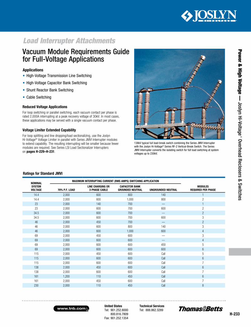
United StatesTel: 901.252.8000 800.816.7809Fax: 901.252.1354
Technical ServicesTel: 888.862.3289www.tnb.com
H-233
Load Interrupter Attachments
Power &
High Voltage — Joslyn Hi-Voltage
® Overhead Reclosers & Switches
Ratings for Standard JMVI
NOMINalSySteMVOltage
MaxIMuM INteRRuptINg CuRReNt (RMS aMpS) SwItCHINg applICatION
MOduleSRequIRed peR pHaSe70% p.F. lOad
lINe CHaRgINg OR 3-pHaSe Cable
CapaCItOR baNkgROuNded NeutRal uNgROuNded NeutRal
14.4 2,000 600 800 140 114.4 2,000 600 1,000 800 223 2,000 140 700 — 123 2,000 600 700 600 2
34.5 2,000 600 700 — 234.5 2,000 600 700 600 346 2,000 450 700 — 246 2,000 600 800 140 346 2,000 600 1,000 600 469 2,000 450 600 — 369 2,000 600 600 — 469 2,000 600 600 450 569 2,000 600 600 600 6115 2,000 450 600 Call 5115 2,000 600 600 Call 6115 2,000 600 600 Call 7138 2,000 450 600 Call 6138 2,000 600 600 Call 7161 1,200 110 450 Call 6161 2,000 450 600 Call 7230 2,000 110 450 Call 8
Vacuum Module Requirements Guide for Full-Voltage Applications
138kV typical full load-break switch combining the Series JMVI Interrupter with the Joslyn Hi-Voltage® Series RF-2 Vertical-Break Switch. The Series JMVI Interrupter converts the isolating switch for full load switching at system voltages up to 230kV.
Reduced Voltage applicationsFor loop switching or parallel switching, each vacuum contact per phase is rated 2,000A interrupting at a peak recovery voltage of 30kV. In most cases, these applications may be served with a single vacuum contact per phase.
applications• High-Voltage Transmission Line Switching
• High-Voltage Capacitor Bank Switching
• Shunt Reactor Bank Switching
• Cable Switching
Voltage limiter extended CapabilityFor loop splitting and line dropping/load sectionalizing, use the Joslyn Hi-Voltage® Voltage Limiter in parallel with Series JMVI Interrupter modules to extend capability. The resulting interrupting will be smaller because fewer modules are required. See Series LSI Load Sectionalizer Interrupters on pages H-229–H-231.
www.tnb.comUnited StatesTel: 901.252.8000 800.816.7809Fax: 901.252.1354
Technical ServicesTel: 888.862.3289
H-234
Load Interrupter Attachments
Pow
er &
Hig
h Vo
ltage
— J
osly
n Hi
-Vol
tage
® O
verh
ead
Recl
oser
s &
Switc
hes Ratings for JMVI with Voltage Limiter
SySteM VoLtageJMVI RequIRed
ModuLeS peR pHaSeCabLe CHaRgIngCuRRent (aMpS)
LIne CHaRgIngCuRRent (aMpS)
paRaLLeL oR LoopSwItCHIng (aMpS)
72.5 2 50 50 2,000121 2 50 15 2,000145 2 10 10 2,000145 3 50 20 2,000169 3 50 25 2,000242 4 15 15 2,000242 5 50 100 2,000
note: To order Joslyn Hi-Voltage® Series JMVI Modular Vac-Rupter Interrupter Attachments, please supply the following information: 1. Air switch manufacturer 2. Switch model number 3. Voltage rating 4. Current rating 5. Size of insulator bolt circle 6. Description of blade movement, including rotation as viewed from hinge end looking back at the jaw assembly end 7. Application, system voltage and grounding